EP3896902A1 - Übertragung von sicherem multicast-datenverkehr über ein rechennetzwerk - Google Patents
Übertragung von sicherem multicast-datenverkehr über ein rechennetzwerk Download PDFInfo
- Publication number
- EP3896902A1 EP3896902A1 EP21154202.2A EP21154202A EP3896902A1 EP 3896902 A1 EP3896902 A1 EP 3896902A1 EP 21154202 A EP21154202 A EP 21154202A EP 3896902 A1 EP3896902 A1 EP 3896902A1
- Authority
- EP
- European Patent Office
- Prior art keywords
- network
- appliance
- multicast data
- network appliance
- data transmission
- Prior art date
- Legal status (The legal status is an assumption and is not a legal conclusion. Google has not performed a legal analysis and makes no representation as to the accuracy of the status listed.)
- Granted
Links
Images



Classifications
-
- H—ELECTRICITY
- H04—ELECTRIC COMMUNICATION TECHNIQUE
- H04L—TRANSMISSION OF DIGITAL INFORMATION, e.g. TELEGRAPHIC COMMUNICATION
- H04L12/00—Data switching networks
- H04L12/28—Data switching networks characterised by path configuration, e.g. LAN [Local Area Networks] or WAN [Wide Area Networks]
- H04L12/46—Interconnection of networks
- H04L12/4633—Interconnection of networks using encapsulation techniques, e.g. tunneling
-
- H—ELECTRICITY
- H04—ELECTRIC COMMUNICATION TECHNIQUE
- H04L—TRANSMISSION OF DIGITAL INFORMATION, e.g. TELEGRAPHIC COMMUNICATION
- H04L12/00—Data switching networks
- H04L12/02—Details
- H04L12/16—Arrangements for providing special services to substations
- H04L12/18—Arrangements for providing special services to substations for broadcast or conference, e.g. multicast
- H04L12/1886—Arrangements for providing special services to substations for broadcast or conference, e.g. multicast with traffic restrictions for efficiency improvement, e.g. involving subnets or subdomains
-
- H—ELECTRICITY
- H04—ELECTRIC COMMUNICATION TECHNIQUE
- H04L—TRANSMISSION OF DIGITAL INFORMATION, e.g. TELEGRAPHIC COMMUNICATION
- H04L12/00—Data switching networks
- H04L12/02—Details
- H04L12/16—Arrangements for providing special services to substations
- H04L12/18—Arrangements for providing special services to substations for broadcast or conference, e.g. multicast
- H04L12/185—Arrangements for providing special services to substations for broadcast or conference, e.g. multicast with management of multicast group membership
-
- H—ELECTRICITY
- H04—ELECTRIC COMMUNICATION TECHNIQUE
- H04L—TRANSMISSION OF DIGITAL INFORMATION, e.g. TELEGRAPHIC COMMUNICATION
- H04L12/00—Data switching networks
- H04L12/28—Data switching networks characterised by path configuration, e.g. LAN [Local Area Networks] or WAN [Wide Area Networks]
- H04L12/46—Interconnection of networks
- H04L12/4641—Virtual LANs, VLANs, e.g. virtual private networks [VPN]
-
- H—ELECTRICITY
- H04—ELECTRIC COMMUNICATION TECHNIQUE
- H04L—TRANSMISSION OF DIGITAL INFORMATION, e.g. TELEGRAPHIC COMMUNICATION
- H04L45/00—Routing or path finding of packets in data switching networks
- H04L45/16—Multipoint routing
-
- H—ELECTRICITY
- H04—ELECTRIC COMMUNICATION TECHNIQUE
- H04L—TRANSMISSION OF DIGITAL INFORMATION, e.g. TELEGRAPHIC COMMUNICATION
- H04L45/00—Routing or path finding of packets in data switching networks
- H04L45/20—Hop count for routing purposes, e.g. TTL
-
- H—ELECTRICITY
- H04—ELECTRIC COMMUNICATION TECHNIQUE
- H04L—TRANSMISSION OF DIGITAL INFORMATION, e.g. TELEGRAPHIC COMMUNICATION
- H04L12/00—Data switching networks
- H04L12/02—Details
- H04L12/16—Arrangements for providing special services to substations
- H04L12/18—Arrangements for providing special services to substations for broadcast or conference, e.g. multicast
- H04L12/1836—Arrangements for providing special services to substations for broadcast or conference, e.g. multicast with heterogeneous network architecture
-
- H—ELECTRICITY
- H04—ELECTRIC COMMUNICATION TECHNIQUE
- H04L—TRANSMISSION OF DIGITAL INFORMATION, e.g. TELEGRAPHIC COMMUNICATION
- H04L45/00—Routing or path finding of packets in data switching networks
- H04L45/50—Routing or path finding of packets in data switching networks using label swapping, e.g. multi-protocol label switch [MPLS]
Definitions
- This disclosure relates generally to the secure and scalable transfer of multicast data over a computing network via a virtual overlay network.
- Certain computing appliances can be utilized to enable an enterprise's SD-WAN (software defined wide area networking) deployment, allowing for zero-touch provisioning, enhanced quality of service, security, and redundancy over any type of network, including basic (public) Internet.
- SD-WAN software defined wide area networking
- customers have historically leased lines from network providers (MPLS is an example of a type of leased line). This means that the provider provisions and configures the network from end-to-end, and the user pays a high price in order to have what is essentially a private network. This also puts them at the mercy of the provider during outages, and gives them little recourse when the provided service is misbehaving, or requires changes to configuration.
- Providing systems and methods to free an enterprise from these limitations of MPLS, and expressly enabling enterprise computers to use basic Internet or other methods of communicating between their offices, provides the enterprise with a low-cost alternative to MPLS, or redundancy alongside MPLS.
- a computing appliance can also function in certain deployments as a replacement for a typical edge-router, by providing the same support for all protocols and applications across any network. In this way, an end-user customer would have to make no special accommodations, and would not need to know nor care whether the underlying traffic was running over MPLS or Internet or other type of network.
- a method for transmitting multicast data over a public communication network by a first network appliance may comprise: receiving at the first network appliance, designated as a rendezvous point for a multicast data transmission, a request from a second network appliance to receive the multicast data transmission; transmitting the multicast data transmission from a transmitting computing device to a virtual interface of the first network appliance; encapsulating the multicast data transmission by the first network appliance into a virtual network overlay transmission; transmitting the virtual network overlay transmission from the first network appliance over the public communication network to the second network appliance; and transmitting the multicast data transmission by the second network appliance to a receiving computing device.
- the embodiments disclosed herein may be implemented using a variety of technologies.
- the methods described herein may be implemented in software executing on a computer system containing one or more computers, or in hardware utilizing either a combination of microprocessors or other specially designed application-specific integrated circuits (ASICs), programmable logic devices, or various combinations thereof.
- the methods described herein may be implemented by a series of computer-executable instructions residing on a storage medium, such as a disk drive, or computer-readable medium.
- the embodiments described herein relate to mechanisms for extending multicast network data traffic over a public WAN in a secure manner.
- multicast is a group communication method whereby data transmission is addressed to a group of destination computers simultaneously.
- Group communication may either be application layer multicast or network assisted multicast, where the latter makes it possible for the source to efficiently send to the group in a single transmission.
- Copies are automatically created in network elements, such as routers, switches and cellular network base stations, but only to network segments that currently contain members of the group.
- Network assisted multicast may be implemented at the data link layer using one-to-many addressing and switching such as Ethernet multicast addressing, Asynchronous Transfer Mode (ATM), point-to-multipoint virtual circuits (P2MP) or Infiniband multicast.
- Network assisted multicast may also be implemented at the Internet layer using IP multicast.
- IP multicast the implementation of the multicast concept occurs at the IP routing level, where routers create optimal distribution paths for datagrams sent to a multicast destination address.
- IP Internet Protocol
- multicast is often employed in Internet Protocol (IP) applications of streaming media, such as IPTV and multipoint videoconferencing.
- Embodiments of the present disclosure may be implemented via Multicast IPv4 protocol as defined by RFC5110, RFC5771, RFC1112 and others.
- Multicast is a routing architecture, allowing for the efficient distribution of traffic broadcasted from a source to multiple destinations.
- the use of multicast IP is widespread but limited due to its implementation. Its salient limitation is that the routing protocols that govern it - most notably PIM - must be configured and run upon all intermediate routers within the network from endpoint to endpoint. Thus, it is useful today only in private networks where these routers may be provisioned and maintained - and therefore wouldn't be used upon the internet itself.
- a videoconferencing application used within a company such that all employees could join would be a good example of an application that would use multicast, whereas streaming a movie from a website would not.
- the customer must request that multicast be enabled on their network, and an IT employee for the MPLS provider must manually configure PIM-SM on all of the routers on the network. If a new branch office router is added, it must also be manually configured.
- multicast's operation can be found in the RFC and other associated documents. Briefly, it consists of a source that doesn't 'broadcast' but instead 'multicasts' its packets to the network. The clients that wish to receive these packets, request to do so by querying the source's unicast address. 'Broadcast' would imply that the source would send packets that all of the hosts on the network would receive. A less efficient method that perhaps had 'sessions' for each source-client pair (as you would with an SSH or HTTP connection) would make it so that the source would send out a copy of each packet of data (such as each frame of video, for example) to each and every one of its recipients. In such a case, if many people wanted to view this particular video feed, the source and the network closest to the source would be overwhelmed with traffic, causing congestion and drops and lower quality of service for each of the recipients. That is, the video streaming quality would be sub-optimal.
- Multicast makes it so that each router along the chain knows which interfaces from which they receive (IIF, incoming interface) and need to send (OIF, outgoing interface) a packet. In this fashion, all of the routers participating in the Multicast routing protocol make it so that the source sends only one packet and that packet is never duplicated until it reaches a router upon which there are two downstream OIFs with ultimately recipient clients downstream from these two interfaces.
- Multicast Group (destination) addresses are identified by a special IP range 224.0.0.0 - 239.255.255.255.
- Protocol Independent Multicast PIM
- SM Sparse Mode
- a single router is typically designated through configuration as an RP (Rendezvous Point).
- RP Central Point
- This router acts as a central figure in the network.
- a source When a source has media to broadcast (e.g., a video feed) it registers by sending a message to its nexthop router. If configured with PIM, this router will make note that it has a source from one of its interfaces (upstream IIF) and will send the control packet on towards the RP on its OIF. In this fashion, it will continue onward throughout all of the routers in the network until it reaches the RP and builds the 'trunk' of a tree pointing back to the root of the source traffic.
- upstream IIF upstream IIF
- each client sends a unicast packet request that is destined to the source.
- Routers participating in PIM will take these 'Join' messages and build branches of the tree back in the other direction from the client to the RP. In this fashion, a tree of paths is built that show where a single packet can traverse to get from source to client. A single packet can travel along this path until it hits a router that has built multiple OIFs - such that the packet must be duplicated and sent out of its multiple paths (on smaller branches). In this fashion, multicast is very efficient - only duplicating packets when absolutely necessary and limiting congestion in the network.
- this PIM-SM protocol 'tree' can only work on a private network managed by a service provider, and not over the broader Internet. That is because the Internet has a great many routers that are out of the control of any one enterprise and the enterprise's network provider. As such, none of these routers are explicitly configured to support PIM and therefore unable to carry multicast traffic.
- Embodiments of the present disclosure describe special purpose computing appliances that can operate a customized version of PIM-SM to make an entire proprietary SD-WAN fabric appear as a single neighboring router. It consists of a generic protocol portion provided by third party metaswitch to provide basic PIM-SM protocol compliance, and a proprietary portion discussed herein. With the proprietary systems and methods discussed herein, a multicast adjacency table is maintained, multicast packets can be processed, and the computing appliances can keep their own routing infrastructure to allow multicast all of the benefits currently available to unicast traffic - including leveraging of customized overlays, IPSec security, redundancy features, quality-of-service, FEC/POC, network-memory, etc.
- PIM-lite Another component, PIM-lite, 'fools' neighboring PIM routers and the PIM-SM protocol to believe that an embodiment of the presently disclosed appliance is a neighboring PIM router, and that other remote appliances are neighboring PIM routers, when in fact there may be many, many routers and hops in between these appliances.
- FIG. 1 illustrates an exemplary system 100, within which the present disclosure can be implemented.
- the exemplary system 100 includes a first location 110, a second location 120, and communication networks 130A-130D. While four communication networks are depicted in exemplary system 100, there can be any number of communication networks, including just one. Additionally, system 100 can include many locations, though only two are depicted in the exemplary figure for simplicity.
- the first location 110 includes computers 140 and a first appliance 150.
- the computers 140 are linked to the first appliance 150. While only one appliance is depicted in first location 110, there can be multiple appliances, physical and/or virtual, at first location 110.
- the first location is a branch location of an enterprise. While not depicted here, first location 110 can also comprise additional elements such as routers, switches, or any other physical or virtual computing equipment.
- Computers 140 may be any type of computing device capable of accessing a communication network, such as a desktop computer, laptop computer, server, mobile phone, tablet, or any other "smart" device configurable for connection to a communication network.
- the first appliance 150 comprises hardware and/or software elements configured to receive data and optionally perform any type of processing before transmitting data across one or more communication networks.
- the first appliance 150 is configured in-line (or serially) between the computers 140 and the router 160.
- the first appliance 150 intercepts network traffic between the computers 140 and the servers 170, in either direction.
- the first appliance 150 can be configured as an additional router, gateway, bridge, or be transparent on some or all interfaces. As a router, for example, the first appliance 150 appears to the computers 140 as an extra hop before the router 160. In some embodiments, the first appliance 150 provides redundant routing or peer routing with the router 160. Additionally, the first appliance 150 may provide failure mechanisms, such as, fail-to-open (e.g., no data access) or fail-to-wire (e.g., a direct connection to the router 160). If an appliance has multiple interfaces, it can be transparent on some interfaces, or act like a router, or act like a bridge on others. Alternatively, the appliance can be transparent on all interfaces, or appear as a router or bridge on all interfaces.
- fail-to-open e.g., no data access
- fail-to-wire e.g., a direct connection to the router 160.
- the first appliance 150 is linked to a router 160, which is coupled to communication networks 130A and 130B. While only one router 160 is depicted in exemplary system 100, there can be multiple routers, switches, or other equipment (physical or virtual) present in system 100, either within the first location 110 or outside of the first location 110. Typically, router 160 would be located within first location 110. In various embodiments, first appliance 150 may be in communication with communication networks 130C and 130D directly (on separate interfaces), instead of through router 160.
- router 160 is depicted as being connected to two communication networks and first appliance 150 is also depicted as being connected to two communication networks, a person of ordinary skill in the art would understand that there can be any number of communication networks (including just one communication network) connected to the first location 110, either via router 160, via first appliance 150, or via another computing device.
- the access links 125 are shown as dashed lines in FIG. 1 .
- the second location 120 in exemplary system 100 includes servers 170. While the term "server” is used herein, any type of computing device may be used in second location 120, as understood by a person of ordinary skill in the art.
- the server may also be a virtual machine.
- second location 120 can optionally include at least one second appliance in addition to, or instead of, servers 170.
- Second location 120 can also include other components not depicted in FIG. 1 , such as routers, switches, load-balancers or any other physical or virtual computing equipment.
- the second location 120 is a central location or data center for an enterprise. In other embodiments, the second location 120 is a data center hosting a public web service or application.
- the servers 170 are depicted in FIG. 1 as being linked to the communication networks 130A-130D via destination access links 145.
- servers 170 may actually be in communication with one or more of the communication networks through a router, switch, second appliance, or other physical or virtual equipment.
- destination access links 145 are depicted in FIG. 1 , for four communication networks (130A-130D), there may actually be fewer (such as just one) or more communication networks connected to second location 120.
- the destination access links 145 are shown as dashed lines in FIG. 1 .
- the communication networks 130A-130D comprise hardware and/or software elements that enable the exchange of information (e.g., voice, video and data) between the first location 110 and the second location 120.
- Some examples of the communication networks 130A-130D are a private wide-area network (WAN), the public Internet, Multiprotocol Label Switching (MPLS) network, and wireless LTE network.
- connections from the first location 110 to the communication networks 130A - 130D are T1 lines (1.544 Mbps), or broadband connections such as digital subscriber lines (DSL) and cable modems.
- each of the communication networks 130A-130D may be connected to at least one other communication network via at least one Inter-ISP link 155.
- communication network 130A may be connected to communication network 130B, 130C, and/or 130D via one or more inter-ISP links.
- Data may traverse more than one communications network along a path from first location 110 to second location 120. For example, traffic may flow from the first location 110 to communication network 130A, over inter-ISP link 155 to communication network 130B, and then to the second location 120.
- the router 160 and first appliance 150 are optionally connected to the communication networks 130A-130D via access links 125, sometimes also referred to herein as network access links.
- the communication networks 130A-130D consist of routers, switches, and other internal components that make up provider links 135.
- the provider links 135 are managed by the network service providers such as an Internet Service Provider (ISP).
- ISP Internet Service Provider
- the second location 120 can be connected to communication networks 130A-130D via destination access links 145. Access links 125, provider links 135, and destination access links 145 can be combined to make various network paths along which data travels between the first location 110 and the second location 120.
- the exemplary embodiment of FIG. 1 depicts two paths along various provider links 135 through each communication network. However, as understood by persons of ordinary skill in the art, there can be any number of network paths across one or more communication networks.
- communication networks may be in communication with one another via inter-ISP link(s) 155.
- data traveling through communication network 130A may also travel through communication network 130C before reaching second location 120.
- data can travel through any one or more of the communication networks 130A-130D from first location 110 to second location 120, and vice versa.
- an inter-ISP link connects communication networks of different internet service providers, such as a link connecting Verizon LTE wireless network with Comcast broadband network.
- an inter-ISP link can connect communication networks from the same internet service provider, such as a link connecting Verizon LTE wireless network with the Verizon Fire network.
- the first appliance 150 along with any other appliances in system 100 can be physical or virtual.
- a virtual appliance can be in a virtual private cloud (VPC), managed by a cloud service provider, such as Amazon Web Services, or others.
- An appliance in a customer data center can be physical or virtual.
- the second location 120 may be a cloud service such as Amazon Web Service, Salesforce, or others.
- the communication networks 130A-130D can comprise multiple provider links, made up of routers and switches, connecting networked devices in different locations. These provider links, which together form various paths, are part of one or more core networks, sometimes referred to as an underlay network. In addition to these paths, there can also be tunnels connecting two networked devices.
- a virtual network sometimes called an overlay network, can be used to transmit data across an underlay network, regardless of which Service Provider manages the routes or provider links. Data from connected devices can travel over this overlay network, which can consist of any number of tunnels or paths between each location.
- data from computers 140 at first location 110 may include voice, video, and data. This information can be transmitted by first appliance 150 over one or more communication networks 130A-130D to second location 120.
- voice, video, and data may be received and transmitted on separate LAN or vLAN interfaces, and first appliance 150 can distinguish the traffic based on the LAN/vLAN interface at which the data was received.
- the system 100 includes one or more secure tunnels between the first appliance 150 and servers 170, or optionally a second appliance at the second location.
- the secure tunnel may be utilized with encryption (e.g., IPsec), access control lists (ACLs), compression (such as header and payload compression), fragmentation/coalescing optimizations, and/or error detection and correction provided by an appliance.
- encryption e.g., IPsec
- ACLs access control lists
- compression such as header and payload compression
- fragmentation/coalescing optimizations e.g., error detection and correction provided by an appliance.
- first location 110 and/or second location 120 can be a branch location, central location, private cloud network, data center, or any other type of location.
- multiple locations can be in communication with each other.
- any type of network topology may be used.
- the system 100 may include multiple branch locations and/or multiple central locations coupled to one or more communication networks.
- System 100 may also include many sites (first locations) in communication with many different public web services (second locations).
- Branch location/branch location communication, central location/central location communication, central location/cloud appliance communication, as well as multi-appliance and/or multi-node communication and bi-directional communication are further within the scope of the disclosure.
- FIG. 1 illustrates the system 100 having a single first location 110 and a single second location 120.
- FIG. 2 illustrates a block diagram of an appliance 250 (also referred to herein as a network appliance), in an exemplary implementation of the invention.
- Appliance 250 may be similar to first appliance 150 of FIG. 1 , as discussed herein.
- the appliance 250 includes a processor 210, a memory 220, a WAN communication interface 230, a LAN communication interface 240, and database(s) 290.
- a system bus 280 links the processor 210, the memory 220, the WAN communication interface 230, the LAN communication interface 240, and the database(s) 290.
- line 260 links the WAN communication interface 230 to the router 160 (in FIG. 1 )
- line 270 links the LAN communication interface 240 to the computers 140 in FIG. 1 .
- the database(s) 290 comprises hardware and/or software elements configured to store data in an organized format to allow the processor 210 to create, modify, and retrieve the data.
- the hardware and/or software elements of the database(s) 290 may include storage devices, such as RAM, hard drives, optical drives, flash memory, and magnetic tape.
- some appliances comprise identical hardware and/or software elements.
- some appliances such as a second appliance, may include hardware and/or software elements providing additional or specialized processing, communication, and storage capacity.
- Embodiments of the present invention also allow for centrally assigned policies to be implemented throughout an organization's entire network, to secure and control all WAN traffic for the organization.
- Software defined WAN (SD-WAN) overlay networks can be created independently from the physical network, and from each other, and in multiple layers. Topology, security, and forwarding rules can be specified independently for each overlay. This design allows for high-scale and secure application segmentation. Each overlay scales automatically as endpoints are added to the SD-WAN fabric, and configuration integrity is maintained as each site maps a local profile into a global overlay.
- SD-WAN Software defined WAN
- All of the overlay networks, labels, and corresponding ports, subnets and vLANs can be maintained in one or more databases in communication with an orchestrator device, as depicted in FIG. 3 .
- the orchestrator 310 can be hardware and/or software, and be in communication with each of the networked devices, such as the network appliances, as well as in communication with the database(s) 320.
- the orchestrator 310 may maintain information regarding the configuration of each appliance at each location (physical or virtual). In this way, the orchestrator 310 can create, manage and implement policies for network traffic throughout the network of connected appliances. For example, if a higher priority is designated for voice traffic, the orchestrator 310 can automatically configure the corresponding network appliances at all relevant locations accordingly.
- the orchestrator 310 can also create and manage tunnels in the enterprise network, including tunnels to carry a particular type of network traffic between each source-destination appliance pair.
- the orchestrator 310 can automatically configure the enterprise network by determining which tunnels need to be set up, and automatically creating them based on the network nodes and overlays.
- the orchestrator 310 can also configure policies based on the application classification techniques to preferentially steer certain types of applications over one path rather than over another path.
- network interfaces of a network appliance 250 can be designated on the WAN side and LAN side as processing a specific type of traffic, or traffic from specific applications.
- a first WAN interface may connect to the public Internet, while a second WAN interface connects to an MPLS service. Both WAN interfaces can support encryption and the Internet uplink can be configured for Network Address Translation (NAT).
- NAT Network Address Translation
- a network appliance supports PIM-SM and IGMP with the help of meta-switch software. Both protocols code are run as a separate process in the appliance called mrtrd (multicast-router-daemon).
- MRTRD is a PIM managed process. It is fully integrated with TMS library for reading/writing configuration bindings.
- MRTRD has two components (threads): TMS-library and meta-switch library.
- TMS-library is run in a separate thread that is responsible for reading the initial configuration reading from the database. It receives configuration commands from CLI/GUI and transforms them into a format known to the meta-switch library and queues it in CMDQ.
- TMS-library thread will monitor CMDQ if commands are available for submitting to meta-switch thread. After submitting a command, it will mark meta-switch thread as BUSY. Typically, only meta-switch thread can un-set a BUSY flag.
- Meta-switch library is the main thread that has meta-switch software. It does the initial setup to run PIM and IGMP protocol code. Main thread/meta-switch thread is responsible for running PIM/IGMP protocols. It also reads configuration from a kernel about interface/vLANs and initial set of routers.
- Both TMS-library thread and meta-switch library thread can share two queues to accomplish the required functionality in a network appliance.
- the shared two queues are CMDQ and NHOPQ. Each of these two queues can be periodically checked to see if any commands need to be processed.
- Commands from CMDQ can be submitted to meta-switch library by the TMS-library thread.
- Commands from NHOPQ can be converted into a request binding and TUNLD can respond to them.
- NHOPQ is used to get unicast routes from TUNLD which are needed for PIM protocol to run. For example, a route to source is needed to do SPT-switch (shortest path switch to source), which can be configured to be a default on a network appliance of the present invention.
- mrtrd operating in an appliance is a process responsible for sending, receiving, and processing of PIM/IGMP control packets.
- Control packets are received by mrtrd via multicast enabled sockets created by meta-switch software.
- mrtrd can configure a kernel to create multicast routes based on PIM control packets. Once the required state is programmed in the kernel by mrtrd, data can be forwarded by the kernel alone.
- SPT-switch over can be initiated by mrtrd, and mrtrd will program the kernel to create a multicast route with ⁇ IIF, OILs> ( ⁇ incoming interface, outgoing interface list>) per group.
- the kernel's multicast route can later be torn down gracefully by mrtrd once it stops receiving PIM control packets. In this way, multicast routes can be added and removed in a scalable and secure manner.
- Unicast RTM is also stored in meta-switch.
- a required route for mrtrd can be fetched from TUNLD.
- multicast data can be forwarded as pass through unshaped by quality of service constraints, in exemplary embodiments.
- Embodiments of the present disclosure can be implemented via a physical or virtual network appliance with at least two standard interfaces (vLAN or Native) on different subnets.
- the interfaces can be LAN or WAN interfaces.
- the network appliance can be configured in a number of different ways, such as a Rendezvous Point (RP) for multicast traffic, an appliance in communication with an external RP, a FHR (First Hop Router) directly connected to a streaming source, a LHR (Last Hop Router) due to IGMP support which is directly connected to end hosts, a MHR (Middle Hop Router) between an RP and LHR.
- the RP or Source of the multicast traffic is reachable on a standard interface and not merely via a network overlay. There may be only one RP address in an enterprise network for all multicast groups, or a plurality of RP addresses in an enterprise network.
- the RP may be configured by a network administrator or automatically.
- one customer data site has data to transmit to hundreds or even thousands of end computing devices in disparate locations.
- an enterprise may wish to broadcast a video message to its many branch locations, an enterprise may wish to send a stock ticker price to multiple bank sites across the country, or an enterprise may wish to play music to customers that are placed on hold across the world.
- this type of multicast network traffic could only be transmitted over an expensive private MPLS network.
- One or more Internet Service Providers (ISPs) stitched together a network hop by hop and charged the enterprise for use of the network.
- ISPs Internet Service Providers
- SD-WAN can be utilized to seamlessly meld together private and public communication networks, so that the SD-WAN provider can carry the multicast traffic over the Internet without the use of any ISPs.
- Public communication networks today typically create point to point links, to stitch together a network manually over IPSec to make it seem like a private network to an end user.
- each individual router and network does not need to be manually configured to carry network traffic. Rather, an end user simply transmits to an edge router of the SD-WAN fabric and does not need to worry about the intermediate hops to the destination computer.
- a source can transmit multicast traffic over a public Internet (and not have to rely on an expensive ISP connection) in a scalable, secure, seamless, and deployment free manner.
- Destination sites can be added or removed to the SD-WAN fabric, without any change necessary from the source side or the destination side of the multicast network traffic.
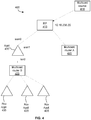
- multicast source 410 has multicast data to transmit.
- Multicast source 410 may send a ping to a known multicast group IP address of 224.8.8.8.
- the designated RP for the network may have an IP address of 10.16.236.20.
- the multicast data traffic may be sent by the RP 415 directly to appliance 430, or to multicast router A 420, and then on to appliance 430.
- Appliance 430 may have the same configuration as appliance 250 discussed herein.
- Appliance 430 may further be configured with 3 deployed interfaces, named wan0, wan1, and lan0. Appliance 430 may first be configured to enable PIM on each of the 3 interfaces. Each time PIM is enabled on an interface, PIM assigns a random 64bit value to it. On each subnet, PIM identifies a designated router, which is responsible PIM control data. Neighboring computing devices for each of the 3 interfaces can also be determined.
- IGMP may be enabled on appliance 430. If appliance 430 has end hosts on either the LAN side or the WAN side, then IGMP may be enabled.
- appliance 430 After enablement, a path to the RP 415 through environment 400 is determined by appliance 430, after it is created in mrtrd. Further, appliance 430 can check that the nexthops on the interfaces are reachable, otherwise PIM neighbors may not be detected by multicast router. If the nexthops on the interfaces are not reachable, then the IP address of RP 415 can be changed.
- multicast source 410 may transmit multicast data for transmission to RP 415.
- RP 415 transmits the data to appliance 430, which in turn transmits the data to multicast router B 425.
- Multicast router B 425 in turn triplicates the data and transmits to each of the 3 receiving appliances 435.
- FIG. 5 depicts an exemplary deployment scenario with three appliances 515, 525, 535 connected via a public WAN in different physical locations.
- Each of the three appliances may be located in different cities around the world. Because they are connected by public WAN, the network connection between them is inherently insecure. They may be connected in any network configuration, which may or may not be a full mesh configuration. Further, the appliances may be part of a centralized data center or a branch center. Each appliance may or may not have a private network connection as well. Further, each appliance may be connected to an orchestrator (such as orchestrator 310 of FIG. 3 ), even though not depicted in the exemplary environment 500 of FIG. 5 . As discussed herein, the orchestrator has a global view of the whole network across the geographical area, and all of the configurations and deployment can occur at the orchestrator itself.
- orchestrator such as orchestrator 310 of FIG. 3
- multicast source 510 is unaware of the creation or setup of the overlay network connecting the appliances 515, 525, 535.
- Appliance A 515 connected to multicast source 510 simply appears to multicast source 510 to be a regular router.
- multicast receiver 530 is unaware of the creation or setup of the overlay network connecting the appliances, as appliance B 525 connected to multicast receiver 530 simply appears to it to be a regular router.
- multicast source 510 may transmit multicast data as a single stream of packets, which is then split across all of the relevant sites seamlessly without a user having to do anything.
- the orchestrator may setup which of the appliances are participants in the multicast network, and use the PIM-SM protocol to create forwarding states as to which overlays to send the data over. This information is computed by PIM-SM protocol running in the appliance A 515 connected to multicast source 510.
- multicast source 510 transmits data and decides which multicasts receivers can receive the data.
- the orchestrator decides how the various devices are connected through the network. With this setup, there is no need to send data all the way to a site (appliance) where no multicast receiver is connected. Thus, appliance 515 does not need to duplicate the data to all connected appliances.
- the receiving device information can be dynamically adjusted.
- a user at receiver 530 may open an application to listen to an enterprise-wide video broadcast.
- Receiver 530 advertises to the network that it is there is to receive the traffic via sending PIM-SM information. This gets transmitted through the network to multicast source 510, which then adds receiver 530 to the network for receiving the multicast data.
- a tree of network paths is created from multicast source 510 to any and all receivers 530 that may be present in environment 500, as discussed herein.
- the tree branches are dynamic as additional receivers can be added at any time and receivers may be dropped at any time. While prior systems built this tree on private networks by service providers, the present disclosure allows for the multicast tree paths to be built using proprietary overlay networks over a public network.
- the overlay network can transform itself into a multicast tree to provide similar functionality to what an ISP can provide over a private network.
- FIG. 5 depicts only one multicast source and one multicast receiver, there can be any number of multicast sources and multicast receivers in environment 500.
- These multiple multicast channels may be broadcasting in isolation and in parallel in the network.
- receiver 530 may inform appliance B 525 that it wishes to join a multicast transmission by transmitting an IGMP-join message to appliance B 525 through a multicast application.
- One appliance in the network is designated as the Rendezvous Point for that multicast traffic, by the orchestrator connecting all of the appliances.
- Each appliance is configured to transmit any such IGMP-join messages to the respective Rendezvous Point, via the overlay network overlay network 520.
- Appliance B 525 as a configuration step in the orchestrator, is configured to know that the IGMP-join message is to be transmitted to the appliance designated as the RP for the requested multicast channel, and transmits the message to the IP address of the RP via the overlay network.
- appliance B 525 Since the protocol is built to understand IP addresses and interfaces (links), not the traditional underlay/overlay network structure, one single virtual link representing the SD-WAN fabric (composed of all of the overlays) is represented to appliance B 525. Otherwise, thousands of interfaces (one for each ovelay) may be present in the environment. Thus, the entire network complexity is hidden and only one neighbor/peer is visible to receiver 530. PIM-SM knows that the RP is reachable via the virtual link. Thus, appliance 525 receives the IGMP-join message from receiver 530, transmits a PIM-join message to the designated RP such that it also receives any packets for the designated multicast IP channel. When appliance B 525 receives the multicast traffic from the RP, since multicast packets are not supported by public networks, appliance B 525 encapsulates the data in a virtual overlay packet and transmits to receiver 530.
- replication is provided over the SD-WAN fabric in a scalable and secure way.
- the replication can be on either the WAN side of an appliance, LAN side of an appliance, or both.
Landscapes
- Engineering & Computer Science (AREA)
- Computer Networks & Wireless Communication (AREA)
- Signal Processing (AREA)
- Computer Security & Cryptography (AREA)
- Data Exchanges In Wide-Area Networks (AREA)
Applications Claiming Priority (1)
| Application Number | Priority Date | Filing Date | Title |
|---|---|---|---|
| US16/852,047 US11425026B2 (en) | 2020-04-17 | 2020-04-17 | Transfer of secure multicast data traffic over a computing network |
Publications (2)
| Publication Number | Publication Date |
|---|---|
| EP3896902A1 true EP3896902A1 (de) | 2021-10-20 |
| EP3896902B1 EP3896902B1 (de) | 2024-10-30 |
Family
ID=74418203
Family Applications (1)
| Application Number | Title | Priority Date | Filing Date |
|---|---|---|---|
| EP21154202.2A Active EP3896902B1 (de) | 2020-04-17 | 2021-01-29 | Übertragung von sicherem multicast-datenverkehr über ein rechennetzwerk |
Country Status (3)
| Country | Link |
|---|---|
| US (2) | US11425026B2 (de) |
| EP (1) | EP3896902B1 (de) |
| CN (1) | CN113542134A (de) |
Cited By (1)
| Publication number | Priority date | Publication date | Assignee | Title |
|---|---|---|---|---|
| CN116032788A (zh) * | 2022-12-22 | 2023-04-28 | 南凌科技股份有限公司 | Sd-wan系统一种单臂部署的方法 |
Families Citing this family (4)
| Publication number | Priority date | Publication date | Assignee | Title |
|---|---|---|---|---|
| US11362849B1 (en) * | 2020-11-23 | 2022-06-14 | Cisco Technology, Inc. | SD-WAN multicast replicator selection centralized policy |
| US11658903B2 (en) * | 2021-04-06 | 2023-05-23 | Arista Networks, Inc. | Network device route programming |
| US12603838B2 (en) * | 2022-03-31 | 2026-04-14 | Lenovo Global Technology (United States) Inc. | Optimizing network load in multicast communications |
| US12199868B2 (en) * | 2022-05-27 | 2025-01-14 | Cisco Technology, Inc. | Optimizing IPSec for hierarchical SD-WAN |
Citations (5)
| Publication number | Priority date | Publication date | Assignee | Title |
|---|---|---|---|---|
| US8645576B2 (en) * | 2007-07-31 | 2014-02-04 | Cisco Technology, Inc. | Overlay transport virtualization |
| EP2930881A1 (de) * | 2014-04-11 | 2015-10-14 | Deutsche Telekom AG | Verfahren und System zur Übertragung einer Protokolldateneinheit über ein Telekommunikationsnetzwerk, Programm und Computerprogrammprodukt |
| US10333828B2 (en) * | 2016-05-31 | 2019-06-25 | Cisco Technology, Inc. | Bidirectional multicasting over virtual port channel |
| US20190207779A1 (en) * | 2017-12-31 | 2019-07-04 | Arista Networks, Inc. | Multicast traffic in a virtual extensible local area network (vxlan) |
| US20190296922A1 (en) * | 2018-03-21 | 2019-09-26 | Nokia Solutions And Networks Oy | Hierarchical bit indexed replication of multicast packets |
Family Cites Families (6)
| Publication number | Priority date | Publication date | Assignee | Title |
|---|---|---|---|---|
| CN101442485B (zh) * | 2008-12-18 | 2011-08-24 | 华为技术有限公司 | 一种组播转发的方法、装置和系统 |
| CN102045179B (zh) * | 2009-10-09 | 2013-01-30 | 杭州华三通信技术有限公司 | 实现本地网络与公共网络间组播互通的方法和nat设备 |
| CN104009926B (zh) * | 2013-02-26 | 2017-04-12 | 杭州华三通信技术有限公司 | Evi网络中的组播方法及边缘设备ed |
| CN104426780B (zh) * | 2013-08-30 | 2018-01-23 | 华为技术有限公司 | 数据转发方法和系统 |
| CN109729009B (zh) | 2017-10-31 | 2022-08-26 | 华为技术有限公司 | 用于实现组播业务的方法和装置 |
| US10608922B2 (en) * | 2018-03-21 | 2020-03-31 | Nokia Solutions And Networks Oy | Hierarchical bit indexed replication of multicast packets |
-
2020
- 2020-04-17 US US16/852,047 patent/US11425026B2/en active Active
-
2021
- 2021-01-26 CN CN202110102787.2A patent/CN113542134A/zh active Pending
- 2021-01-29 EP EP21154202.2A patent/EP3896902B1/de active Active
- 2021-08-03 US US17/393,191 patent/US11824759B2/en active Active
Patent Citations (5)
| Publication number | Priority date | Publication date | Assignee | Title |
|---|---|---|---|---|
| US8645576B2 (en) * | 2007-07-31 | 2014-02-04 | Cisco Technology, Inc. | Overlay transport virtualization |
| EP2930881A1 (de) * | 2014-04-11 | 2015-10-14 | Deutsche Telekom AG | Verfahren und System zur Übertragung einer Protokolldateneinheit über ein Telekommunikationsnetzwerk, Programm und Computerprogrammprodukt |
| US10333828B2 (en) * | 2016-05-31 | 2019-06-25 | Cisco Technology, Inc. | Bidirectional multicasting over virtual port channel |
| US20190207779A1 (en) * | 2017-12-31 | 2019-07-04 | Arista Networks, Inc. | Multicast traffic in a virtual extensible local area network (vxlan) |
| US20190296922A1 (en) * | 2018-03-21 | 2019-09-26 | Nokia Solutions And Networks Oy | Hierarchical bit indexed replication of multicast packets |
Cited By (2)
| Publication number | Priority date | Publication date | Assignee | Title |
|---|---|---|---|---|
| CN116032788A (zh) * | 2022-12-22 | 2023-04-28 | 南凌科技股份有限公司 | Sd-wan系统一种单臂部署的方法 |
| CN116032788B (zh) * | 2022-12-22 | 2023-08-11 | 南凌科技股份有限公司 | Sd-wan系统一种单臂部署的方法 |
Also Published As
| Publication number | Publication date |
|---|---|
| US20210377154A1 (en) | 2021-12-02 |
| US11824759B2 (en) | 2023-11-21 |
| EP3896902B1 (de) | 2024-10-30 |
| US20210328909A1 (en) | 2021-10-21 |
| US11425026B2 (en) | 2022-08-23 |
| CN113542134A (zh) | 2021-10-22 |
Similar Documents
| Publication | Publication Date | Title |
|---|---|---|
| EP3896902B1 (de) | Übertragung von sicherem multicast-datenverkehr über ein rechennetzwerk | |
| CN101019382B (zh) | 通过环形拓扑实现多点服务 | |
| CN101019377B (zh) | 用于提供有效多点网络服务的方法 | |
| US7835378B2 (en) | Root node redundancy for multipoint-to-multipoint transport trees | |
| US8339973B1 (en) | Multicast traceroute over MPLS/BGP IP multicast VPN | |
| US20060187950A1 (en) | Architecture and provisioning tools for managed multicast virtual private LAN trees | |
| US8611346B1 (en) | Multicast sparse-mode source redundancy | |
| EP3965368B1 (de) | Auswahl des replikationsmodus für multicast-mehrfachsendung in einem evpn | |
| US20150043348A1 (en) | Traffic Flow Redirection between Border Routers using Routing Encapsulation | |
| CN109196819B (zh) | 虚拟端口信道上的双向多播 | |
| US9008118B2 (en) | Multicast data delivery over mixed multicast and non-multicast networks | |
| JP4654278B2 (ja) | マルチキャストツリー割当方法および装置 | |
| US12149440B2 (en) | Multicast redundancy in EVPN networks | |
| CN100417141C (zh) | 一种组播业务实现方法 | |
| US12549401B2 (en) | Optimal multicast forwarding for sources behind EVPN fabric | |
| CN113497766B (zh) | 使用源激活路由的evpn组播入口转发器选择 | |
| US20240022444A1 (en) | Upstream multicast hop (umh) extensions for anycast deployments | |
| CN113630320A (zh) | 计算机网络内创建隧道的方法、入口网络装置及存储介质 | |
| US20250247326A1 (en) | Local Bias Support For Multiprotocol Label Switching Networks | |
| Zhou et al. | A Solution for IP Multicast VPNs based on Virtual Routers | |
| Borcoci | Architectures for Networks and Services | |
| Borcoci | Advanced Technologies TCP/IP |
Legal Events
| Date | Code | Title | Description |
|---|---|---|---|
| PUAI | Public reference made under article 153(3) epc to a published international application that has entered the european phase |
Free format text: ORIGINAL CODE: 0009012 |
|
| STAA | Information on the status of an ep patent application or granted ep patent |
Free format text: STATUS: THE APPLICATION HAS BEEN PUBLISHED |
|
| AK | Designated contracting states |
Kind code of ref document: A1 Designated state(s): AL AT BE BG CH CY CZ DE DK EE ES FI FR GB GR HR HU IE IS IT LI LT LU LV MC MK MT NL NO PL PT RO RS SE SI SK SM TR |
|
| B565 | Issuance of search results under rule 164(2) epc |
Effective date: 20210621 |
|
| STAA | Information on the status of an ep patent application or granted ep patent |
Free format text: STATUS: REQUEST FOR EXAMINATION WAS MADE |
|
| 17P | Request for examination filed |
Effective date: 20220407 |
|
| RBV | Designated contracting states (corrected) |
Designated state(s): AL AT BE BG CH CY CZ DE DK EE ES FI FR GB GR HR HU IE IS IT LI LT LU LV MC MK MT NL NO PL PT RO RS SE SI SK SM TR |
|
| RAP1 | Party data changed (applicant data changed or rights of an application transferred) |
Owner name: SILVER PEAK SYSTEMS, INC |
|
| RAP1 | Party data changed (applicant data changed or rights of an application transferred) |
Owner name: HEWLETT PACKARD ENTERPRISE DEVELOPMENT LP |
|
| STAA | Information on the status of an ep patent application or granted ep patent |
Free format text: STATUS: EXAMINATION IS IN PROGRESS |
|
| 17Q | First examination report despatched |
Effective date: 20230622 |
|
| GRAP | Despatch of communication of intention to grant a patent |
Free format text: ORIGINAL CODE: EPIDOSNIGR1 |
|
| STAA | Information on the status of an ep patent application or granted ep patent |
Free format text: STATUS: GRANT OF PATENT IS INTENDED |
|
| INTG | Intention to grant announced |
Effective date: 20240607 |
|
| GRAS | Grant fee paid |
Free format text: ORIGINAL CODE: EPIDOSNIGR3 |
|
| GRAA | (expected) grant |
Free format text: ORIGINAL CODE: 0009210 |
|
| STAA | Information on the status of an ep patent application or granted ep patent |
Free format text: STATUS: THE PATENT HAS BEEN GRANTED |
|
| AK | Designated contracting states |
Kind code of ref document: B1 Designated state(s): AL AT BE BG CH CY CZ DE DK EE ES FI FR GB GR HR HU IE IS IT LI LT LU LV MC MK MT NL NO PL PT RO RS SE SI SK SM TR |
|
| REG | Reference to a national code |
Ref country code: GB Ref legal event code: FG4D |
|
| REG | Reference to a national code |
Ref country code: CH Ref legal event code: EP |
|
| REG | Reference to a national code |
Ref country code: IE Ref legal event code: FG4D |
|
| REG | Reference to a national code |
Ref country code: DE Ref legal event code: R096 Ref document number: 602021020846 Country of ref document: DE |
|
| REG | Reference to a national code |
Ref country code: LT Ref legal event code: MG9D |
|
| REG | Reference to a national code |
Ref country code: NL Ref legal event code: MP Effective date: 20241030 |
|
| PG25 | Lapsed in a contracting state [announced via postgrant information from national office to epo] |
Ref country code: PT Free format text: LAPSE BECAUSE OF FAILURE TO SUBMIT A TRANSLATION OF THE DESCRIPTION OR TO PAY THE FEE WITHIN THE PRESCRIBED TIME-LIMIT Effective date: 20250228 Ref country code: IS Free format text: LAPSE BECAUSE OF FAILURE TO SUBMIT A TRANSLATION OF THE DESCRIPTION OR TO PAY THE FEE WITHIN THE PRESCRIBED TIME-LIMIT Effective date: 20250228 Ref country code: HR Free format text: LAPSE BECAUSE OF FAILURE TO SUBMIT A TRANSLATION OF THE DESCRIPTION OR TO PAY THE FEE WITHIN THE PRESCRIBED TIME-LIMIT Effective date: 20241030 |
|
| PG25 | Lapsed in a contracting state [announced via postgrant information from national office to epo] |
Ref country code: FI Free format text: LAPSE BECAUSE OF FAILURE TO SUBMIT A TRANSLATION OF THE DESCRIPTION OR TO PAY THE FEE WITHIN THE PRESCRIBED TIME-LIMIT Effective date: 20241030 Ref country code: NL Free format text: LAPSE BECAUSE OF FAILURE TO SUBMIT A TRANSLATION OF THE DESCRIPTION OR TO PAY THE FEE WITHIN THE PRESCRIBED TIME-LIMIT Effective date: 20241030 |
|
| REG | Reference to a national code |
Ref country code: AT Ref legal event code: MK05 Ref document number: 1738014 Country of ref document: AT Kind code of ref document: T Effective date: 20241030 |
|
| PG25 | Lapsed in a contracting state [announced via postgrant information from national office to epo] |
Ref country code: BG Free format text: LAPSE BECAUSE OF FAILURE TO SUBMIT A TRANSLATION OF THE DESCRIPTION OR TO PAY THE FEE WITHIN THE PRESCRIBED TIME-LIMIT Effective date: 20241030 |
|
| PG25 | Lapsed in a contracting state [announced via postgrant information from national office to epo] |
Ref country code: ES Free format text: LAPSE BECAUSE OF FAILURE TO SUBMIT A TRANSLATION OF THE DESCRIPTION OR TO PAY THE FEE WITHIN THE PRESCRIBED TIME-LIMIT Effective date: 20241030 |
|
| PG25 | Lapsed in a contracting state [announced via postgrant information from national office to epo] |
Ref country code: NO Free format text: LAPSE BECAUSE OF FAILURE TO SUBMIT A TRANSLATION OF THE DESCRIPTION OR TO PAY THE FEE WITHIN THE PRESCRIBED TIME-LIMIT Effective date: 20250130 |
|
| PG25 | Lapsed in a contracting state [announced via postgrant information from national office to epo] |
Ref country code: AT Free format text: LAPSE BECAUSE OF FAILURE TO SUBMIT A TRANSLATION OF THE DESCRIPTION OR TO PAY THE FEE WITHIN THE PRESCRIBED TIME-LIMIT Effective date: 20241030 Ref country code: LV Free format text: LAPSE BECAUSE OF FAILURE TO SUBMIT A TRANSLATION OF THE DESCRIPTION OR TO PAY THE FEE WITHIN THE PRESCRIBED TIME-LIMIT Effective date: 20241030 Ref country code: GR Free format text: LAPSE BECAUSE OF FAILURE TO SUBMIT A TRANSLATION OF THE DESCRIPTION OR TO PAY THE FEE WITHIN THE PRESCRIBED TIME-LIMIT Effective date: 20250131 |
|
| PG25 | Lapsed in a contracting state [announced via postgrant information from national office to epo] |
Ref country code: PL Free format text: LAPSE BECAUSE OF FAILURE TO SUBMIT A TRANSLATION OF THE DESCRIPTION OR TO PAY THE FEE WITHIN THE PRESCRIBED TIME-LIMIT Effective date: 20241030 |
|
| PG25 | Lapsed in a contracting state [announced via postgrant information from national office to epo] |
Ref country code: RS Free format text: LAPSE BECAUSE OF FAILURE TO SUBMIT A TRANSLATION OF THE DESCRIPTION OR TO PAY THE FEE WITHIN THE PRESCRIBED TIME-LIMIT Effective date: 20250130 |
|
| PG25 | Lapsed in a contracting state [announced via postgrant information from national office to epo] |
Ref country code: SM Free format text: LAPSE BECAUSE OF FAILURE TO SUBMIT A TRANSLATION OF THE DESCRIPTION OR TO PAY THE FEE WITHIN THE PRESCRIBED TIME-LIMIT Effective date: 20241030 |
|
| PG25 | Lapsed in a contracting state [announced via postgrant information from national office to epo] |
Ref country code: DK Free format text: LAPSE BECAUSE OF FAILURE TO SUBMIT A TRANSLATION OF THE DESCRIPTION OR TO PAY THE FEE WITHIN THE PRESCRIBED TIME-LIMIT Effective date: 20241030 |
|
| PG25 | Lapsed in a contracting state [announced via postgrant information from national office to epo] |
Ref country code: EE Free format text: LAPSE BECAUSE OF FAILURE TO SUBMIT A TRANSLATION OF THE DESCRIPTION OR TO PAY THE FEE WITHIN THE PRESCRIBED TIME-LIMIT Effective date: 20241030 |
|
| PG25 | Lapsed in a contracting state [announced via postgrant information from national office to epo] |
Ref country code: RO Free format text: LAPSE BECAUSE OF FAILURE TO SUBMIT A TRANSLATION OF THE DESCRIPTION OR TO PAY THE FEE WITHIN THE PRESCRIBED TIME-LIMIT Effective date: 20241030 |
|
| PG25 | Lapsed in a contracting state [announced via postgrant information from national office to epo] |
Ref country code: SK Free format text: LAPSE BECAUSE OF FAILURE TO SUBMIT A TRANSLATION OF THE DESCRIPTION OR TO PAY THE FEE WITHIN THE PRESCRIBED TIME-LIMIT Effective date: 20241030 |
|
| PG25 | Lapsed in a contracting state [announced via postgrant information from national office to epo] |
Ref country code: CZ Free format text: LAPSE BECAUSE OF FAILURE TO SUBMIT A TRANSLATION OF THE DESCRIPTION OR TO PAY THE FEE WITHIN THE PRESCRIBED TIME-LIMIT Effective date: 20241030 |
|
| PG25 | Lapsed in a contracting state [announced via postgrant information from national office to epo] |
Ref country code: IT Free format text: LAPSE BECAUSE OF FAILURE TO SUBMIT A TRANSLATION OF THE DESCRIPTION OR TO PAY THE FEE WITHIN THE PRESCRIBED TIME-LIMIT Effective date: 20241030 |
|
| REG | Reference to a national code |
Ref country code: DE Ref legal event code: R097 Ref document number: 602021020846 Country of ref document: DE |
|
| REG | Reference to a national code |
Ref country code: CH Ref legal event code: PL |
|
| PLBE | No opposition filed within time limit |
Free format text: ORIGINAL CODE: 0009261 |
|
| STAA | Information on the status of an ep patent application or granted ep patent |
Free format text: STATUS: NO OPPOSITION FILED WITHIN TIME LIMIT |
|
| PG25 | Lapsed in a contracting state [announced via postgrant information from national office to epo] |
Ref country code: SE Free format text: LAPSE BECAUSE OF FAILURE TO SUBMIT A TRANSLATION OF THE DESCRIPTION OR TO PAY THE FEE WITHIN THE PRESCRIBED TIME-LIMIT Effective date: 20241030 |
|
| PG25 | Lapsed in a contracting state [announced via postgrant information from national office to epo] |
Ref country code: LU Free format text: LAPSE BECAUSE OF NON-PAYMENT OF DUE FEES Effective date: 20250129 Ref country code: MC Free format text: LAPSE BECAUSE OF FAILURE TO SUBMIT A TRANSLATION OF THE DESCRIPTION OR TO PAY THE FEE WITHIN THE PRESCRIBED TIME-LIMIT Effective date: 20241030 |
|
| 26N | No opposition filed |
Effective date: 20250731 |
|
| PG25 | Lapsed in a contracting state [announced via postgrant information from national office to epo] |
Ref country code: BE Free format text: LAPSE BECAUSE OF NON-PAYMENT OF DUE FEES Effective date: 20250131 |
|
| PG25 | Lapsed in a contracting state [announced via postgrant information from national office to epo] |
Ref country code: FR Free format text: LAPSE BECAUSE OF NON-PAYMENT OF DUE FEES Effective date: 20250131 |
|
| PG25 | Lapsed in a contracting state [announced via postgrant information from national office to epo] |
Ref country code: CH Free format text: LAPSE BECAUSE OF NON-PAYMENT OF DUE FEES Effective date: 20250131 |
|
| REG | Reference to a national code |
Ref country code: BE Ref legal event code: MM Effective date: 20250131 |
|
| PG25 | Lapsed in a contracting state [announced via postgrant information from national office to epo] |
Ref country code: IE Free format text: LAPSE BECAUSE OF NON-PAYMENT OF DUE FEES Effective date: 20250129 |
|
| PGFP | Annual fee paid to national office [announced via postgrant information from national office to epo] |
Ref country code: GB Payment date: 20260126 Year of fee payment: 6 |
|
| PGFP | Annual fee paid to national office [announced via postgrant information from national office to epo] |
Ref country code: DE Payment date: 20260127 Year of fee payment: 6 |