EP3896480A1 - Beam formation device, radar device, and beam formation method - Google Patents
Beam formation device, radar device, and beam formation method Download PDFInfo
- Publication number
- EP3896480A1 EP3896480A1 EP19909707.2A EP19909707A EP3896480A1 EP 3896480 A1 EP3896480 A1 EP 3896480A1 EP 19909707 A EP19909707 A EP 19909707A EP 3896480 A1 EP3896480 A1 EP 3896480A1
- Authority
- EP
- European Patent Office
- Prior art keywords
- doppler
- unit
- target
- calculated
- signal
- Prior art date
- Legal status (The legal status is an assumption and is not a legal conclusion. Google has not performed a legal analysis and makes no representation as to the accuracy of the status listed.)
- Granted
Links
Images




Classifications
-
- G—PHYSICS
- G01—MEASURING; TESTING
- G01S—RADIO DIRECTION-FINDING; RADIO NAVIGATION; DETERMINING DISTANCE OR VELOCITY BY USE OF RADIO WAVES; LOCATING OR PRESENCE-DETECTING BY USE OF THE REFLECTION OR RERADIATION OF RADIO WAVES; ANALOGOUS ARRANGEMENTS USING OTHER WAVES
- G01S13/00—Systems using the reflection or reradiation of radio waves, e.g. radar systems; Analogous systems using reflection or reradiation of waves whose nature or wavelength is irrelevant or unspecified
- G01S13/02—Systems using reflection of radio waves, e.g. primary radar systems; Analogous systems
- G01S13/04—Systems determining presence of a target
-
- G—PHYSICS
- G01—MEASURING; TESTING
- G01S—RADIO DIRECTION-FINDING; RADIO NAVIGATION; DETERMINING DISTANCE OR VELOCITY BY USE OF RADIO WAVES; LOCATING OR PRESENCE-DETECTING BY USE OF THE REFLECTION OR RERADIATION OF RADIO WAVES; ANALOGOUS ARRANGEMENTS USING OTHER WAVES
- G01S13/00—Systems using the reflection or reradiation of radio waves, e.g. radar systems; Analogous systems using reflection or reradiation of waves whose nature or wavelength is irrelevant or unspecified
- G01S13/02—Systems using reflection of radio waves, e.g. primary radar systems; Analogous systems
- G01S13/0218—Very long range radars, e.g. surface wave radar, over-the-horizon or ionospheric propagation systems
-
- G—PHYSICS
- G01—MEASURING; TESTING
- G01S—RADIO DIRECTION-FINDING; RADIO NAVIGATION; DETERMINING DISTANCE OR VELOCITY BY USE OF RADIO WAVES; LOCATING OR PRESENCE-DETECTING BY USE OF THE REFLECTION OR RERADIATION OF RADIO WAVES; ANALOGOUS ARRANGEMENTS USING OTHER WAVES
- G01S13/00—Systems using the reflection or reradiation of radio waves, e.g. radar systems; Analogous systems using reflection or reradiation of waves whose nature or wavelength is irrelevant or unspecified
- G01S13/02—Systems using reflection of radio waves, e.g. primary radar systems; Analogous systems
- G01S13/50—Systems of measurement based on relative movement of target
-
- G—PHYSICS
- G01—MEASURING; TESTING
- G01S—RADIO DIRECTION-FINDING; RADIO NAVIGATION; DETERMINING DISTANCE OR VELOCITY BY USE OF RADIO WAVES; LOCATING OR PRESENCE-DETECTING BY USE OF THE REFLECTION OR RERADIATION OF RADIO WAVES; ANALOGOUS ARRANGEMENTS USING OTHER WAVES
- G01S3/00—Direction-finders for determining the direction from which infrasonic, sonic, ultrasonic or electromagnetic waves, or particle emission, not having a directional significance, are being received
- G01S3/02—Direction-finders for determining the direction from which infrasonic, sonic, ultrasonic or electromagnetic waves, or particle emission, not having a directional significance, are being received using radio waves
- G01S3/74—Multi-channel systems specially adapted for direction-finding, i.e. having a single antenna system capable of giving simultaneous indications of the directions of different signals
-
- G—PHYSICS
- G01—MEASURING; TESTING
- G01S—RADIO DIRECTION-FINDING; RADIO NAVIGATION; DETERMINING DISTANCE OR VELOCITY BY USE OF RADIO WAVES; LOCATING OR PRESENCE-DETECTING BY USE OF THE REFLECTION OR RERADIATION OF RADIO WAVES; ANALOGOUS ARRANGEMENTS USING OTHER WAVES
- G01S7/00—Details of systems according to groups G01S13/00, G01S15/00, G01S17/00
- G01S7/02—Details of systems according to groups G01S13/00, G01S15/00, G01S17/00 of systems according to group G01S13/00
- G01S7/28—Details of pulse systems
- G01S7/285—Receivers
- G01S7/292—Extracting wanted echo-signals
-
- G—PHYSICS
- G01—MEASURING; TESTING
- G01S—RADIO DIRECTION-FINDING; RADIO NAVIGATION; DETERMINING DISTANCE OR VELOCITY BY USE OF RADIO WAVES; LOCATING OR PRESENCE-DETECTING BY USE OF THE REFLECTION OR RERADIATION OF RADIO WAVES; ANALOGOUS ARRANGEMENTS USING OTHER WAVES
- G01S7/00—Details of systems according to groups G01S13/00, G01S15/00, G01S17/00
- G01S7/02—Details of systems according to groups G01S13/00, G01S15/00, G01S17/00 of systems according to group G01S13/00
- G01S7/35—Details of non-pulse systems
- G01S7/352—Receivers
- G01S7/354—Extracting wanted echo-signals
-
- H—ELECTRICITY
- H01—ELECTRIC ELEMENTS
- H01Q—ANTENNAS, i.e. RADIO AERIALS
- H01Q3/00—Arrangements for changing or varying the orientation or the shape of the directional pattern of the waves radiated from an antenna or antenna system
- H01Q3/26—Arrangements for changing or varying the orientation or the shape of the directional pattern of the waves radiated from an antenna or antenna system varying the relative phase or relative amplitude of energisation between two or more active radiating elements; varying the distribution of energy across a radiating aperture
- H01Q3/2605—Array of radiating elements provided with a feedback control over the element weights, e.g. adaptive arrays
-
- G—PHYSICS
- G01—MEASURING; TESTING
- G01S—RADIO DIRECTION-FINDING; RADIO NAVIGATION; DETERMINING DISTANCE OR VELOCITY BY USE OF RADIO WAVES; LOCATING OR PRESENCE-DETECTING BY USE OF THE REFLECTION OR RERADIATION OF RADIO WAVES; ANALOGOUS ARRANGEMENTS USING OTHER WAVES
- G01S13/00—Systems using the reflection or reradiation of radio waves, e.g. radar systems; Analogous systems using reflection or reradiation of waves whose nature or wavelength is irrelevant or unspecified
- G01S13/02—Systems using reflection of radio waves, e.g. primary radar systems; Analogous systems
- G01S13/0218—Very long range radars, e.g. surface wave radar, over-the-horizon or ionospheric propagation systems
- G01S2013/0227—OTH, Over-The-Horizon radar
-
- Y—GENERAL TAGGING OF NEW TECHNOLOGICAL DEVELOPMENTS; GENERAL TAGGING OF CROSS-SECTIONAL TECHNOLOGIES SPANNING OVER SEVERAL SECTIONS OF THE IPC; TECHNICAL SUBJECTS COVERED BY FORMER USPC CROSS-REFERENCE ART COLLECTIONS [XRACs] AND DIGESTS
- Y02—TECHNOLOGIES OR APPLICATIONS FOR MITIGATION OR ADAPTATION AGAINST CLIMATE CHANGE
- Y02A—TECHNOLOGIES FOR ADAPTATION TO CLIMATE CHANGE
- Y02A90/00—Technologies having an indirect contribution to adaptation to climate change
- Y02A90/10—Information and communication technologies [ICT] supporting adaptation to climate change, e.g. for weather forecasting or climate simulation
Definitions
- the present invention relates to a beam formation device, a radar device, and a beam formation method for forming an adaptive beam.
- a high frequency surface wave radar is a radar that detects an over-the-horizon target beyond the horizon by utilizing the characteristics of short radio waves that propagate along the surface of the sea.
- a transmission wave which is a radio wave radiated from the HFSWR, propagates along the surface of the sea and is reflected on the target or the like on or above the sea.
- the transmission wave reflected by the target or the like is received by the HFSWR as a target signal.
- a portion of the transmission wave radiated from the HFSWR propagates to the sky and is reflected by the ionosphere in the atmosphere.
- the transmission wave reflected by the ionosphere is received by the HFSWR as an ionospheric clutter.
- the HFSWR When the HFSWR receives a radio wave including a mix of the target signal and the ionospheric clutter in a range-Doppler cell, the signal to clutter plus noiser ratio (SCNR) is deteriorated, so that performance for detecting the target is deteriorated.
- SCNR signal to clutter plus noiser ratio
- adaptive weighting used for forming the adaptive beam is obtained for each range bin in order to suppress ionospheric clutters having different characteristics for each range bin.
- the target signal may also be suppressed together with the ionospheric clutter.
- Patent Literature 1 discloses a radar that avoids a situation in which a target signal is suppressed together with an ionospheric clutter.
- the radar disclosed in Patent Literature 1 When receiving a radio wave including the ionospheric clutter and the target signal by a reception array, the radar disclosed in Patent Literature 1 forms a beam from a reception signal of the radio wave using a set weighting, and calculates a Doppler spectrum from the formed beam.
- the Doppler spectrum calculated from the formed beam includes not only the Doppler spectrum of the target signal having peak power but also the Doppler spectrum of the ionospheric clutter having a wider bandwidth than the Doppler spectrum of the target signal.
- the radar disclosed in Patent Literature 1 compares the power of the calculated Doppler spectrum and a threshold, and searches for a peak power larger than the power of the Doppler spectrum of the ionospheric clutter in the calculated Doppler spectrum.
- the peak power larger than the power of the Doppler spectrum of the ionospheric clutter is the peak power of the Doppler spectrum of the target signal.
- the radar disclosed in Patent Literature 1 forms an adaptive beam for each range bin by using a reception signal other than the reception signal of a Doppler bin corresponding to the peak power obtained through the search among the reception signals for each range bin including the ionospheric clutter.
- Patent Literature 1 US 7,145,503
- the peak power of the Doppler spectrum of the target signal When the peak power of the Doppler spectrum of the target signal is smaller than the power of the Doppler spectrum of the ionospheric clutter, the peak power of the Doppler spectrum of the target signal may be buried in the power of the Doppler spectrum of the ionospheric clutter. Therefore, in the radar disclosed in Patent Literature 1, when the peak power of the Doppler spectrum of the target signal is smaller than the power of the Doppler spectrum of the ionospheric clutter, it is difficult to detect the peak power of the Doppler spectrum of the target signal even by comparing the calculated power of the Doppler spectrum and the threshold.
- Patent Literature 1 has a problem that, when the peak power of the Doppler spectrum of the target signal cannot be detected, the situation where the target signal is suppressed together with the ionospheric clutter cannot be avoided.
- the present invention has been made to solve the above problem, and an object of the present invention is to provide a beam formation device, a radar device, and a beam formation method, each of which can avoid a situation in which, even if the peak power of the Doppler spectrum of the target signal is smaller than the power of the Doppler spectrum of the ionospheric clutter, the target signal is suppressed together with the ionospheric clutter.
- the beam formation device includes: a Doppler analysis unit for calculating a Doppler spectrum from a reception signal of each of a plurality of reception antennas, and calculating a reception signal vector including the Doppler spectrum calculated from the reception signal of each of the reception antennas; a correlation matrix calculation unit for calculating a correlation matrix regarding the reception signal vector calculated by the Doppler analysis unit; a Doppler bin detection unit for detecting a target Doppler bin that is a Doppler bin in which a target signal is present from the correlation matrix calculated by the correlation matrix calculation unit and the reception signal vector calculated by the Doppler analysis unit; a target signal removal unit for removing, from the correlation matrix calculated by the correlation matrix calculation unit, the target signal in the target Doppler bin detected by the Doppler bin detection unit so as to calculate a target-signal-removed correlation matrix from which the target signal has been removed; a weighting calculation unit for calculating an adaptive weighting of the reception signal vector calculated by the Doppler analysis unit from the target-sign
- the beam formation device includes: the Doppler bin detection unit that detects a target Doppler bin which is a Doppler bin in which a target signal is present, from the correlation matrix calculated by the correlation matrix calculation unit and the reception signal vector calculated by the Doppler analysis unit; the target signal removal unit that removes, from the correlation matrix calculated by the correlation matrix calculation unit, the target signal in the target Doppler bin detected by the Doppler bin detection unit and thereby calculates a target-signal-removed correlation matrix from which the target signal has been removed; and the weighting calculation unit that calculates an adaptive weighting of the reception signal vector calculated by the Doppler analysis unit from the target-signal-removed correlation matrix calculated by the target signal removal unit.
- the beam formation unit forms an adaptive beam from the reception signal vector calculated by the Doppler analysis unit and the adaptive weighting calculated by the weighting calculation unit. Accordingly, the beam formation device according to the present invention can avoid a situation in which, even if the peak power of the Doppler spectrum of the target signal is smaller than the power of the Doppler spectrum of the ionospheric clutter, the target signal is suppressed together with the ionospheric clutter.
- FIG. 1 is a diagram showing a configuration of a radar device including a beam formation device according to a first embodiment.
- FIG. 2 is a hardware configuration diagram showing hardware of a signal processing unit 2 and a target detection unit 9 in the beam formation device according to the first embodiment.
- the reception antenna 1-m receives a target signal and an ionospheric clutter, and outputs a reception signal including the target signal and the ionospheric clutter to a Doppler analysis unit 3.
- a transmission antenna or the like (not shown) of the radar device radiates, for example, a shortwave radio wave as a transmission wave.
- the target signal is a reflected wave of the transmission wave reflected on a target on or above the sea and returned to the radar device, after the transmission wave is radiated from the transmission antenna and propagates along the surface of the sea.
- the ionospheric clutter is a reflected wave of the transmission wave reflected on the ionosphere in the atmosphere and returned to the radar device, after the transmission wave is radiated from the transmission antenna and propagates to the sky.
- the signal processing unit 2 includes a Doppler analysis unit 3, a correlation matrix calculation unit 4, a Doppler bin detection unit 5, a target signal removal unit 6, a weighting calculation unit 7, and a beam formation unit 8.
- the Doppler analysis unit 3 includes M Doppler analysis processing units 3a-1 to 3a-M and a reception signal vector calculation unit 3b.
- the Doppler analysis unit 3 calculates Doppler spectra x m,k (n) for each range bin (k) from the reception signals of the respective reception antennas 1-m in the reception antennas 1-1 to 1-M.
- N is an integer greater than or equal to 2.
- the Doppler analysis unit 3 calculates, for each range bin (k), a reception signal vector x k (n) including M Doppler spectra x m,k (n) for the range bin (k) calculated from the reception signals of the respective reception antennas 1-m.
- the Doppler analysis unit 3 outputs the calculated reception signal vector x k (n) for each range bin (k) to the correlation matrix calculation unit 4, the Doppler bin detection unit 5, and the beam formation unit 8.
- the Doppler analysis processing unit 3a-m is achieved by, for example, a Doppler analysis processing circuit 21 shown in FIG. 2 .
- the Doppler analysis processing unit 3a-m calculates, for each range bin (k), a Doppler spectrum x m,k (n) by Fourier transformation of the reception signal of the reception antenna 1-m, for example.
- the Doppler analysis processing unit 3a-m outputs the calculated Doppler spectrum x m,k (n) for each range bin (k) to the reception signal vector calculation unit 3b.
- the reception signal vector calculation unit 3b is achieved by, for example, a vector calculation circuit 22 shown in FIG. 2 .
- the reception signal vector calculation unit 3b calculates, for each range bin (k), a reception signal vector x k (n) including M Doppler spectra x m,k (n) in the range bin (k) calculated by the Doppler analysis processing units 3a-1 to 3a-M.
- the reception signal vector calculation unit 3b outputs the calculated reception signal vector x k (n) for each range bin (k) to the correlation matrix calculation unit 4, the Doppler bin detection unit 5, and the beam formation unit 8.
- the correlation matrix calculation unit 4 is achieved by, for example, a correlation matrix calculation circuit 23 shown in FIG. 2 .
- the correlation matrix calculation unit 4 calculates, for each range bin (k), a correlation matrix R x,k hat regarding the reception signal vector x k (n) for each range bin (k) calculated by the Doppler analysis unit 3.
- R x,k hat the correlation matrix R x,k hat regarding the reception signal vector x k (n) for each range bin (k) calculated by the Doppler analysis unit 3.
- the correlation matrix calculation unit 4 outputs the calculated correlation matrix R x,k hat to the Doppler bin detection unit 5 and the target signal removal unit 6.
- the Doppler bin detection unit 5 is achieved by, for example, a Doppler bin detection circuit 24 shown in FIG. 2 .
- the Doppler bin detection unit 5 detects, for each range bin (k), a target Doppler bin n s,k which is a Doppler bin where the target signal is present, from the correlation matrix R x,k hat for each range bin (k) calculated by the correlation matrix calculation unit 4 and the reception signal vector x k (n) for each range bin (k) calculated by the Doppler analysis unit 3.
- the Doppler bin detection unit 5 outputs the detected target Doppler bin n s,k for each range bin (k) to the target signal removal unit 6.
- the target signal removal unit 6 is achieved by, for example, a target signal removal circuit 25 shown in FIG. 2 .
- the target signal removal unit 6 removes the target signal in the target Doppler bin n s,k for each range bin (k) detected by the Doppler bin detection unit 5 from the correlation matrix R x,k hat for each range bin (k) calculated by the correlation matrix calculation unit 4 and thereby calculates, for each range bin (k), a target-signal-removed correlation matrix R x,k (Pro) hat from which the target signal has been removed.
- the symbol “ ⁇ " cannot be written above the character "R x,k (Pro) " because of the electronic application, so it is written as "R x,k (Pro) hat".
- the target signal removal unit 6 outputs the calculated target-signal-removed correlation matrix R x,k (Pro) hat for each range bin (k) to the weighting calculation unit 7.
- the weighting calculation unit 7 is achieved by, for example, a weighting calculation circuit 26 shown in FIG. 2 .
- the weighting calculation unit 7 calculates an adaptive weighting w A,k of the reception signal vector x k (n) for each range bin (k) from the target-signal-removed correlation matrix R x,k (Pro) hat for each range bin (k) calculated by the target signal removal unit 6.
- the weighting calculation unit 7 outputs the calculated adaptive weighting w A,k for each range bin (k) to the beam formation unit 8.
- the beam formation unit 8 is achieved by, for example, a beam formation circuit 27 shown in FIG. 2 .
- the beam formation unit 8 forms, for each range bin (k), an adaptive beam y k (n) on the basis of the reception signal vector x k (n) for each range bin (k) calculated by the Doppler analysis unit 3 and the adaptive weighting w A,k for each range bin (k) calculated by the weighting calculation unit 7.
- the beam formation unit 8 outputs the formed adaptive beam y k (n) for each range bin (k) to the target detection unit 9.
- the target detection unit 9 is achieved by, for example, a target detection circuit 28 shown in FIG. 2 .
- the target detection unit 9 detects a target from the adaptive beam y k (n) for each range bin (k) formed by the beam formation unit 8.
- the Doppler analysis processing units 3a-1 to 3aM, the reception signal vector calculation unit 3b, the correlation matrix calculation unit 4, the Doppler bin detection unit 5, the target signal removal unit 6, the weighting calculation unit 7, the beam formation unit 8, and the target detection unit 9, those of which are the components of the signal processing unit 2, are each achieved by dedicated hardware shown in FIG. 2 . That is, it is assumed that the signal processing unit 2 is achieved by the Doppler analysis processing circuit 21, the vector calculation circuit 22, the correlation matrix calculation circuit 23, the Doppler bin detection circuit 24, the target signal removal circuit 25, the weighting calculation circuit 26, and the beam formation circuit 27. Further, it is assumed that the target detection unit 9 is achieved by the target detection circuit 28.
- each of the Doppler analysis processing circuit 21, the vector calculation circuit 22, the correlation matrix calculation circuit 23, the Doppler bin detection circuit 24, the target signal removal circuit 25, the weighting calculation circuit 26, the beam formation circuit 27, and the target detection circuit 28 is, for example, a single circuit, a composite circuit, a programmed processor, a parallel programmed processor, an application specific integrated circuit (ASIC), a field-programmable gate array (FPGA), or a combination of some of these circuits.
- ASIC application specific integrated circuit
- FPGA field-programmable gate array
- Each of the components of the signal processing unit 2 and the target detection unit 9 are not limited to what is implemented by dedicated hardware.
- the signal processing unit 2 and the target detection unit 9 may be implemented by software, firmware, or a combination of software and firmware.
- the computer means hardware that executes the program, and may be, for example, a central processing unit (CPU), a central processor, a processing unit, a computing unit, a microprocessor, a microcomputer, a processor, or a digital signal processor (DSP).
- CPU central processing unit
- DSP digital signal processor
- FIG. 3 is a diagram showing a hardware configuration of a computer when the signal processing unit 2 and the target detection unit 9 are achieved by software, firmware, or the like.
- a program to cause the computer to execute the processing procedures performed in the Doppler analysis processing units 3a-1 to 3a-M, the reception signal vector calculation unit 3b, the correlation matrix calculation unit 4, the Doppler bin detection unit 5, the target signal removal unit 6, the weighting calculation unit 7, the beam formation unit 8, and the target detection unit 9 is stored in a memory 31. Then, the processor 32 of the computer executes the program stored in the memory 31.
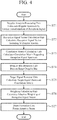
- FIG. 4 is a flowchart showing a beam formation method which is a processing procedure of the signal processing unit 2.
- FIG. 2 shows an example in which the components of the signal processing unit 2 and the target detection unit 9 are achieved by dedicated hardware
- FIG. 3 shows an example in which the signal processing unit 2 and the target detection unit 9 are achieved by software, firmware, or the like.
- the signal processing unit 2 or the target detection unit 9 may be achieved by dedicated hardware
- the remaining components or the target detection unit 9 may be achieved by software, firmware, or the like.
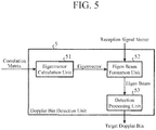
- FIG. 5 is a diagram showing a configuration of the Doppler bin detection unit 5 in the beam formation device according to the first embodiment.
- an eigenvector calculation unit 51 calculates, for each range bin (k), multiple eigenvectors e m,k in the correlation matrix R x,k hat for each range bin (k) calculated by the correlation matrix calculation unit 4.
- the eigenvector calculation unit 51 outputs the calculated multiple eigenvectors e m,k for each range bin (k) to an eigen beam formation unit 52.
- the eigen beam formation unit 52 forms, for each range bin (k), multiple eigen beams z m,k (n) on the basis of the multiple eigenvectors e m,k calculated by the eigenvector calculation unit 51 and the reception signal vector x k (n) calculated by the Doppler analysis unit 3, using the multiple eigenvectors e m,k as beam weighting for the reception signal vector x k (n).
- the eigen beam formation unit 52 outputs the formed multiple eigen beams z m,k (n) for each range bin (k) to a detection processing unit 53.
- the detection processing unit 53 compares, for each range bin (k), the Doppler spectra of the multiple eigen beams z m,k (n) formed by the eigen beam formation unit 52 with a threshold Th.
- the detection processing unit 53 detects a target Doppler bin n s,k on the basis of the comparison result between the Doppler spectra of the multiple eigen beams z m,k (n) and the threshold Th.
- the detection processing unit 53 outputs the detected target Doppler bin n s,k for each range bin (k) to the target signal removal unit 6.
- the threshold Th may be stored in an internal memory of the detection processing unit 53 or may be given from the outside.
- the transmission wave radiated from the transmission antenna of the radar device shown in FIG. 1 or transmission wave radiated from a transmission antenna of a radar device different from the radar device shown in FIG. 1 propagates along the surface of the sea and is reflected by a target on or above the sea.
- the transmission wave reflected by the target propagates along the sea surface as a target signal and is received by the reception antennas 1-1 to 1-M.
- the transmission wave reflected by the ionosphere in the atmosphere propagates in the air as an ionospheric clutter and is received by the reception antennas 1-1 to 1-M.
- the Doppler analysis processing unit 3a-m calculates the Doppler spectrum x m,k (n) for each range bin (k) by, for example, Fourier transformation of the reception signal from the reception antenna 1-m (step ST1 in FIG. 4 ).
- the Doppler analysis processing unit 3a-m outputs the calculated Doppler spectrum x m,k (n) for each range bin (k) to the reception signal vector calculation unit 3b.
- the Doppler spectrum x k (n) includes one target signal vector s k (n) and one ionospheric clutter vector c k (n) for the sake of simplicity.
- the Doppler spectrum x k (n) may include two or more target signal vectors s k (n).
- the Doppler spectrum x k (n) may include two or more ionospheric clutter vectors c k (n).
- Equation (2) the sea clutter received by the reception antenna 1-m is omitted.
- Sea clutter is a reflected wave from the surface of the sea.
- the Doppler bin in which the Doppler spectrum of the sea clutter is distributed is determined by the Bragg scattering frequency determined by the wavelength of the transmission wave and the like.
- the reception signal vector calculation unit 3b can remove the sea clutter from the reception signal vector x k (n) by changing the reception signal of the Doppler bin in which the Doppler spectrum of the sea clutter is distributed to zero.
- the target signal vector s k (n) for each range bin (k) is expressed by the following Equation (3).
- Equation (3) s k (n) in bold is the target signal vector in range bin (k), and s k (n) in lightface is the Doppler spectrum of the target signal in the range bin (k).
- a k ( ⁇ s,k ) is a steering vector with respect to the direction of arrival ⁇ s,k of the target signal in the range bin (k). Since the steering vector a k ( ⁇ s,k ) is a vector, a k ( ⁇ s,k ) is indicated in bold in Equation (3). However, in the text of the specification, the characters cannot be written in bold because of the electronic application, so a k (0s, k ) is written in lightface in the text of the specification.
- p s,k is the power of the target signal in the range bin (k) received by the reception antenna 1-m
- n s,k is the target Doppler bin in the range bin (k)
- ⁇ s,k is an initial phase regarding the target signal in the range bin (k)
- sinc(n-n s,k ) is a sinc function that represents the shape of the Doppler spectrum s k (n) of the target signal.
- the Doppler spectrum s k (n) of the target signal is expressed by the following Equation (4), and is obtained by the N-point Fourier transform of the complex sine wave which is the time series data of the target signal.
- s k n p s , k sinc n ⁇ n s , k exp j ⁇ s , k
- c k (n) a k ⁇ c , k c k n
- Equation (5) c k (n) in bold is the ionospheric clutter vector in range bin (k), and c k (n) in lightface is the Doppler spectrum of the ionospheric clutter in the range bin (k).
- a k ( ⁇ c,k ) is a steering vector with respect to the direction of arrival ⁇ c,k of the ionospheric clutter in the range bin (k). Since the steering vector a k ( ⁇ c,k ) is a vector, a k ( ⁇ c,k ) is indicated in bold in Equation (5). However, in the text of the specification, the characters cannot be written in bold because of the electronic application, so a k ( ⁇ c,k ) is written in lightface in the text of the specification.
- the Doppler spectrum c k (n) of the ionospheric clutter has a wider bandwidth than the doppler spectrum s k (n) of the target signal.
- the widening degree of the bandwidth of the Doppler spectrum c k (n) of the ionospheric clutter and the shape of the Doppler spectrum c k (n) differ depending on the state of the ionosphere.
- the noise vector noise k (n) for each range bin (k) is a white noise spectrum that is uncorrelated between the reception signals received by the reception antennas 1-1 to 1-M.
- the average noise power of the noise vectors noise m,k (n) in the range bin (k) received by the reception antennas 1-1 to 1-M is ⁇ 2 .
- the correlation matrix calculation unit 4 calculates, for each range bin (k), the correlation matrix R x,k hat regarding the reception signal vector x k (n) in the range bin (k) as represented by Equation (6) below (step ST3 in FIG. 4 ).
- Equation (6) H is a symbol indicating transposition.
- the correlation matrix calculation unit 4 outputs the calculated correlation matrix R x,k hat for each range bin (k) to the Doppler bin detection unit 5 and the target signal removal unit 6.
- Equation (7) D is the matrix rank of the incoming wave for the ionospheric clutter and the matrix rank of the incoming wave for the target signal, and D ⁇ M is established.
- the subspace where the eigenvector e m,k of the incoming wave spans and the subspace where the steering vector a k (0s, k ) regarding the direction of arrival ⁇ s,k of the target signal and the steering vector a k ( ⁇ c,k ) regarding the direction of arrival ⁇ c,k of the ionospheric clutter span are the same.
- the eigenvectors e 1,k and e 2,k of the incoming wave in the range bin (k) can be represented by the linear combination of the steering vectors a k (0s, k ) and a k ( ⁇ c,k ) as expressed in Equations (9) and (10) below.
- e 1 , k ⁇ 11 a k ⁇ s , k + ⁇ 12 a k ⁇ c , k e 2
- k ⁇ 21 a k ⁇ s , k + ⁇ 22 a k ⁇ c , k
- Equations (9) and (10) ⁇ 11 , ⁇ 12 , ⁇ 21 , and ⁇ 22 are coupling coefficients.
- the Doppler bin detection unit 5 detects, for each range bin (k), a target Doppler bin n s,k from the correlation matrix R x,k hat for each range bin (k) and the reception signal vector x k (n) for each range bin (k) calculated by the Doppler analysis unit 3 (step ST4 in FIG. 4 ).
- the Doppler bin detection unit 5 outputs the detected target Doppler bin n s,k for each range bin (k) to the target signal removal unit 6.
- the eigenvector calculation unit 51 calculates, for each range bin (k), multiple eigenvectors e m,k of the incoming wave in the correlation matrix R x,k hat for each range bin (k) calculated by the correlation matrix calculation unit 4.
- the eigenvector calculation unit 51 outputs the calculated multiple eigenvectors of the incoming wave to the eigen beam formation unit 52.
- the eigen beam formation unit 52 acquires the eigenvectors for each range bin (k) calculated by the eigenvector calculation unit 51 as beam weightings for the reception signal vector x k (n) of the range bin (k).
- the eigen beam formation unit 52 forms, for each range bin (k), multiple eigen beams z m,k (n) of the incoming wave from the acquired eigenvectors for each range bin (k) and reception signal vector x k (n) for each range bin (k).
- the eigen beam formation unit 52 outputs the formed multiple eigen beams z m,k (n) of the incoming wave for each range bin (k) to the detection processing unit 53.
- Equation (11) the eigen beam z 1,k (n) of the incoming wave is expressed by Equation (11) below.
- Equation (11) The approximation of the last line in Equation (11) is based on the approximation indicated in Equation (14) below, assuming that the direction of arrival ⁇ s,k of the target signal and the direction of arrival ⁇ c,k of the ionospheric clutter are distant from each other.
- Equation (14) a k H ⁇ c , k a k ⁇ s , k ⁇ 0
- Equation (15) the eigen beam z 2,k (n) of the incoming wave is expressed by Equation (15) below.
- Equation (19) ⁇ m1 and ⁇ m2 are coupling coefficients.
- the eigen beams z 1,k (n) and z 2,k (n) of the incoming wave have amplitudes obtained by combining the target Doppler spectrum having a peak in the target Doppler bin n s,k and the ionospheric clutter with a wider bandwidth.
- the noise eigen beam has an amplitude of a white noise spectrum.
- the detection processing unit 53 compares, for each range bin (k), the Doppler spectra of the multiple eigen beams z m,k (n) formed by the eigen beam formation unit 52 with the threshold Th.
- the detection processing unit 53 detects a Doppler bin corresponding to the Doppler spectrum larger than the threshold Th as a target Doppler bin n s,k on the basis of the comparison result between the Doppler spectra of the multiple eigen beams z m,k (n) and the threshold Th.
- the detection processing unit 53 outputs the detected target Doppler bin n s,k for each range bin (k) to the target signal removal unit 6.
- the detection processing unit 53 can set the threshold Th using, for example, constant false alarm rate (CFAR) processing.
- CFAR constant false alarm rate
- the detection processing unit 53 outputs the detected target Doppler bin n s,k to the target signal removal unit 6.
- the reason why the detection processing unit 53 compares the Doppler spectra of all the eigen beams z m,k (n) formed by the eigen beam formation unit 52 with the threshold Th is because it is difficult to classify the eigen beam of the incoming wave and the eigen beam of noise in advance.
- the target signal removal unit 6 acquires the correlation matrix R x,k hat for each range bin (k) calculated by the correlation matrix calculation unit 4 and the target Doppler bin n s,k for each range bin (k) detected by the Doppler bin detection unit 5.
- the target signal removal unit 6 removes the target signal in the target Doppler bin n s,k for the range bin (k) from the correlation matrix R x,k hat for the range bin (k) and thereby calculates, for each range bin (k), a target-signal-removed correlation matrix R x,k (Pro) hat from which the target signal has been removed (step ST5 in FIG. 4 ).
- R ⁇ x , k Pro R ⁇ x , k ⁇ x k n s , k x k n s , k H
- the target signal removal unit 6 outputs the calculated target-signal-removed correlation matrix R x,k (Pro) hat for each range bin (k) to the weighting calculation unit 7.
- the weighting calculation unit 7 acquires the target-signal-removed correlation matrix R x,k (Pro) hat for each range bin (k) calculated by the target signal removal unit 6.
- Equation (20) ⁇ 0 is the direction of the main beam in the adaptive beam y k (n) formed by the beam formation unit 8 described later, and ⁇ is a normalization coefficient.
- the normalization coefficient ⁇ may be stored in the internal memory of the weighting calculation unit 7, or may be given from the outside. Further, the normalization coefficient ⁇ may assume any value as long as it normalizes the adaptive weighting w A,k .
- the weighting calculation unit 7 outputs the calculated adaptive weighting w A,k for each range bin (k) to the beam formation unit 8.
- the beam formation unit 8 acquires the reception signal vector x k (n) for each range bin (k) calculated by the Doppler analysis unit 3 and the adaptive weighting w A,k for each range bin (k) calculated by the weighting calculation unit 7.
- the beam formation unit 8 forms, for each range bin (k), the adaptive beam y k (n) from the reception signal vector x k (n) for the range bin (k) and the adaptive weighting w A,K of the range bin (k) (step ST7 in FIG. 4 ).
- y k n w A , k H x k n
- the adaptive beam y k (n) of the range bin (k) formed by the beam formation unit 8 is a beam in which nulls are formed in the direction of arrival ⁇ c,k of the ionospheric clutter in the range bin (k) and the target signal arrives in the main beam.
- the beam formation unit 8 outputs the formed adaptive beam y k (n) for each range bin (k) to the target detection unit 9.
- the target detection unit 9 acquires the adaptive beam y k (n) for each range bin (k) formed by the beam formation unit 8.
- the target detection unit 9 detects a target from the adaptive beam y k (n) of the range bin (k) by performing a target detection process such as multiple signal classification (MUSIC) method for each range bin (k).
- a target detection process such as multiple signal classification (MUSIC) method for each range bin (k).
- the beam formation device includes: the Doppler bin detection unit 5 that detects a target Doppler bin which is a Doppler bin in which a target signal is present, from the correlation matrix calculated by the correlation matrix calculation unit 4 and the reception signal vector calculated by the Doppler analysis unit 3; the target signal removal unit 6 that removes, from the correlation matrix calculated by the correlation matrix calculation unit 4, the target signal in the target Doppler bin detected by the Doppler bin detection unit 5 and thereby calculates a target-signal-removed correlation matrix from which the target signal has been removed; and the weighting calculation unit 7 that calculates an adaptive weighting of the reception signal vector calculated by the Doppler analysis unit 3 from the target-signal-removed correlation matrix calculated by the target signal removal unit 6.
- the beam formation unit 8 of the beam formation device forms an adaptive beam from the reception signal vector calculated by the Doppler analysis unit 3 and the adaptive weighting calculated by the weighting calculation unit 7. Accordingly, the beam formation device can avoid a situation in which, even if the peak power of the Doppler spectrum of the target signal is smaller than the power of the Doppler spectrum of the ionospheric clutter, the target signal is suppressed together with the ionospheric clutter.
- the second embodiment describes a beam formation device including a signal synthesis unit 10 for generating a synthesis signal of one or more reception signals.
- FIG. 6 is a diagram showing a configuration of a radar device including a beam formation device according to the second embodiment.
- FIG. 7 is a hardware configuration diagram showing hardware of a signal processing unit 2 and a target detection unit 9 in the beam formation device according to the second embodiment.
- FIGS. 6 and 7 elements same as or corresponding to the elements in FIGS. 1 and 2 are identified by the same reference numerals, and the description thereof will be omitted.
- the signal synthesis unit 10 is achieved by, for example, a signal synthesis circuit 29 shown in FIG. 7 .
- the signal synthesis unit 10 generates, for each combination of one or more reception signals among J reception signals in the reception antennas 1-1 to 1-J, a synthesis signal of one or more reception signals included in the combination.
- the signal synthesis unit 10 outputs the generated synthesis signals to the Doppler analysis processing units 3a-1 to 3a-M.
- the signal synthesis unit 10 the Doppler analysis processing units 3a-1 to 3a-M, the reception signal vector calculation unit 3b, the correlation matrix calculation unit 4, the Doppler bin detection unit 5, the target signal removal unit 6, the weighting calculation unit 7, the beam formation unit 8, and the target detection unit 9, those of which are the components of the signal processing unit 2, are each achieved by dedicated hardware as shown in FIG. 7 . That is, it is assumed that the signal processing unit 2 is achieved by the signal synthesis circuit 29, the Doppler analysis processing circuit 21, the vector calculation circuit 22, the correlation matrix calculation circuit 23, the Doppler bin detection circuit 24, the target signal removal circuit 25, the weighting calculation circuit 26, and the beam formation circuit 27. Further, it is assumed that the target detection unit 9 is achieved by the target detection circuit 28.
- each of the signal synthesis circuit 29, the Doppler analysis processing circuit 21, the vector calculation circuit 22, the correlation matrix calculation circuit 23, the Doppler bin detection circuit 24, the target signal removal circuit 25, the weighting calculation circuit 26, the beam formation circuit 27, and the target detection circuit 28 is, for example, a single circuit, a composite circuit, a programmed processor, a parallel programmed processor, an ASIC, an FPGA, or a combination of some of these circuits.
- Each of the components of the signal processing unit 2 and the target detection unit 9 are not limited to what is implemented by dedicated hardware.
- the signal processing unit 2 and the target detection unit 9 may be implemented by software, firmware, or a combination of software and firmware.
- a program to cause the computer to execute the processing procedures performed in the signal synthesis unit 10 the Doppler analysis processing units 3a-1 to 3a-M, the reception signal vector calculation unit 3b, the correlation matrix calculation unit 4, the Doppler bin detection unit 5, the target signal removal unit 6, the weighting calculation unit 7, the beam formation unit 8, and the target detection unit 9 is stored in the memory 31 shown in FIG. 3 .
- the processor 32 of the computer shown in FIG. 3 executes the program stored in the memory 31.
- the signal synthesis unit 10 acquires J reception signals output from the reception antennas 1-1 to 1-J.
- M combinations are determined in advance as combinations of one or more reception signals among J reception signals.
- Any combination may be used as M combinations, and the M combinations are stored in an internal memory of the signal synthesis unit 10.
- the M combinations may be given from the outside.
- Conceivable examples of M combinations of two reception signals include a combination of the reception signal of the reception antenna 1-1 and the reception signal of the reception antenna 1-2, a combination of the reception signal of the reception antenna 1-2 and the reception signal of the reception antenna 1-3, ... a combination of the reception signal of the reception antenna 1-(J-1) and the reception signal of the reception antenna 1-J, and a combination of the reception signal of the reception antenna 1-J and the reception signal of the reception antenna 1-1.
- Conceivable examples of M combinations of three reception signals include a combination of the reception signal of the reception antenna 1-1, the reception signal of the reception antenna 1-2, and the reception signal of the reception antenna 1-3, a combination of the reception signal of the reception antenna 1-2, the reception signal of the reception antenna 1-3, and the reception signal of the reception antenna 1-4, ... and a combination of the reception signal of the reception antenna 1-(J-2), the reception signal of the reception antenna 1-(J-1), and the reception signal of the reception antenna 1-J.
- the signal synthesis unit 10 generates, for each combination, a synthesis signal of one or more reception signals included in the combination, and outputs the generated M synthesis signals to the Doppler analysis processing units 3a-1 to 3a-M.
- the synthesis signal generated by the signal synthesis unit 10 corresponds to a sub-array beam, and the signal synthesis unit 10 can form a sub-array beam in a direction corresponding to a combination of one or more reception signals.
- the Doppler analysis processing unit 3a-m calculates the Doppler spectrum x m,k (n) for each range bin (k) by Fourier transformation of one of the M synthesis signals output from the signal synthesis unit 10 instead of the reception signal from the reception antenna 1-m.
- the Doppler analysis processing unit 3a-m outputs the calculated Doppler spectrum x m,k (n) for each range bin (k) to the reception signal vector calculation unit 3b.
- the subsequent processing is the same as that of the radar device shown in FIG. 1 , and thus, detailed description thereof will be omitted.
- the present invention is suitable for a beam formation device, a radar device, and a beam formation method for forming an adaptive beam.
Landscapes
- Engineering & Computer Science (AREA)
- Radar, Positioning & Navigation (AREA)
- Remote Sensing (AREA)
- Physics & Mathematics (AREA)
- General Physics & Mathematics (AREA)
- Computer Networks & Wireless Communication (AREA)
- Radar Systems Or Details Thereof (AREA)
- Variable-Direction Aerials And Aerial Arrays (AREA)
Abstract
Description
- The present invention relates to a beam formation device, a radar device, and a beam formation method for forming an adaptive beam.
- A high frequency surface wave radar (HFSWR) is a radar that detects an over-the-horizon target beyond the horizon by utilizing the characteristics of short radio waves that propagate along the surface of the sea.
- A transmission wave, which is a radio wave radiated from the HFSWR, propagates along the surface of the sea and is reflected on the target or the like on or above the sea. The transmission wave reflected by the target or the like is received by the HFSWR as a target signal.
- A portion of the transmission wave radiated from the HFSWR propagates to the sky and is reflected by the ionosphere in the atmosphere. The transmission wave reflected by the ionosphere is received by the HFSWR as an ionospheric clutter.
- When the HFSWR receives a radio wave including a mix of the target signal and the ionospheric clutter in a range-Doppler cell, the signal to clutter plus noiser ratio (SCNR) is deteriorated, so that performance for detecting the target is deteriorated.
- As a method for addressing deterioration in performance for detecting a target, there is a method of generating an adaptive beam formed with a null in the direction of arrival of the ionospheric clutter and receiving the target signal arriving in the main beam of the generated adaptive beam.
- In the above method, adaptive weighting used for forming the adaptive beam is obtained for each range bin in order to suppress ionospheric clutters having different characteristics for each range bin. However, when the HFSWR forms an adaptive beam using the adaptive weighting obtained for each range bin in a case where the target signal is mixed in a reception signal for each range bin including the ionospheric clutter, the target signal may also be suppressed together with the ionospheric clutter.
-
Patent Literature 1 below discloses a radar that avoids a situation in which a target signal is suppressed together with an ionospheric clutter. - When receiving a radio wave including the ionospheric clutter and the target signal by a reception array, the radar disclosed in
Patent Literature 1 forms a beam from a reception signal of the radio wave using a set weighting, and calculates a Doppler spectrum from the formed beam. - The Doppler spectrum calculated from the formed beam includes not only the Doppler spectrum of the target signal having peak power but also the Doppler spectrum of the ionospheric clutter having a wider bandwidth than the Doppler spectrum of the target signal.
- The radar disclosed in
Patent Literature 1 compares the power of the calculated Doppler spectrum and a threshold, and searches for a peak power larger than the power of the Doppler spectrum of the ionospheric clutter in the calculated Doppler spectrum. The peak power larger than the power of the Doppler spectrum of the ionospheric clutter is the peak power of the Doppler spectrum of the target signal. - The radar disclosed in
Patent Literature 1 forms an adaptive beam for each range bin by using a reception signal other than the reception signal of a Doppler bin corresponding to the peak power obtained through the search among the reception signals for each range bin including the ionospheric clutter. - Patent Literature 1:
US 7,145,503 - When the peak power of the Doppler spectrum of the target signal is smaller than the power of the Doppler spectrum of the ionospheric clutter, the peak power of the Doppler spectrum of the target signal may be buried in the power of the Doppler spectrum of the ionospheric clutter. Therefore, in the radar disclosed in
Patent Literature 1, when the peak power of the Doppler spectrum of the target signal is smaller than the power of the Doppler spectrum of the ionospheric clutter, it is difficult to detect the peak power of the Doppler spectrum of the target signal even by comparing the calculated power of the Doppler spectrum and the threshold. - The radar disclosed in
Patent Literature 1 has a problem that, when the peak power of the Doppler spectrum of the target signal cannot be detected, the situation where the target signal is suppressed together with the ionospheric clutter cannot be avoided. - The present invention has been made to solve the above problem, and an object of the present invention is to provide a beam formation device, a radar device, and a beam formation method, each of which can avoid a situation in which, even if the peak power of the Doppler spectrum of the target signal is smaller than the power of the Doppler spectrum of the ionospheric clutter, the target signal is suppressed together with the ionospheric clutter.
- The beam formation device according to the present invention includes: a Doppler analysis unit for calculating a Doppler spectrum from a reception signal of each of a plurality of reception antennas, and calculating a reception signal vector including the Doppler spectrum calculated from the reception signal of each of the reception antennas; a correlation matrix calculation unit for calculating a correlation matrix regarding the reception signal vector calculated by the Doppler analysis unit; a Doppler bin detection unit for detecting a target Doppler bin that is a Doppler bin in which a target signal is present from the correlation matrix calculated by the correlation matrix calculation unit and the reception signal vector calculated by the Doppler analysis unit; a target signal removal unit for removing, from the correlation matrix calculated by the correlation matrix calculation unit, the target signal in the target Doppler bin detected by the Doppler bin detection unit so as to calculate a target-signal-removed correlation matrix from which the target signal has been removed; a weighting calculation unit for calculating an adaptive weighting of the reception signal vector calculated by the Doppler analysis unit from the target-signal-removed correlation matrix calculated by the target signal removal unit; and a beam formation unit for forming an adaptive beam from the reception signal vector calculated by the Doppler analysis unit and the adaptive weighting calculated by the weighting calculation unit.
- According to the present invention, the beam formation device includes: the Doppler bin detection unit that detects a target Doppler bin which is a Doppler bin in which a target signal is present, from the correlation matrix calculated by the correlation matrix calculation unit and the reception signal vector calculated by the Doppler analysis unit; the target signal removal unit that removes, from the correlation matrix calculated by the correlation matrix calculation unit, the target signal in the target Doppler bin detected by the Doppler bin detection unit and thereby calculates a target-signal-removed correlation matrix from which the target signal has been removed; and the weighting calculation unit that calculates an adaptive weighting of the reception signal vector calculated by the Doppler analysis unit from the target-signal-removed correlation matrix calculated by the target signal removal unit. The beam formation unit forms an adaptive beam from the reception signal vector calculated by the Doppler analysis unit and the adaptive weighting calculated by the weighting calculation unit. Accordingly, the beam formation device according to the present invention can avoid a situation in which, even if the peak power of the Doppler spectrum of the target signal is smaller than the power of the Doppler spectrum of the ionospheric clutter, the target signal is suppressed together with the ionospheric clutter.
-
-
FIG. 1 is a diagram showing a configuration of a radar device including a beam formation device according to a first embodiment. -
FIG. 2 is a hardware configuration diagram showing hardware of asignal processing unit 2 and atarget detection unit 9 in the beam formation device according to the first embodiment. -
FIG. 3 is a diagram showing a hardware configuration of a computer when thesignal processing unit 2 and thetarget detection unit 9 are achieved by software, firmware, or the like. -
FIG. 4 is a flowchart showing a beam formation method which is a processing procedure of thesignal processing unit 2. -
FIG. 5 is a diagram showing a configuration of a Dopplerbin detection unit 5 in the beam formation device according to the first embodiment. -
FIG. 6 is a diagram showing a configuration of a radar device including a beam formation device according to a second embodiment. -
FIG. 7 is a hardware configuration diagram showing hardware of asignal processing unit 2 and atarget detection unit 9 in the beam formation device according to the second embodiment. - In order to describe the present invention in more detail, a mode for carrying out the present invention will now be described with reference to the accompanying drawings.
-
FIG. 1 is a diagram showing a configuration of a radar device including a beam formation device according to a first embodiment. -
FIG. 2 is a hardware configuration diagram showing hardware of asignal processing unit 2 and atarget detection unit 9 in the beam formation device according to the first embodiment. - In
FIGS. 1 and2 , areception array 1 has M ("M" is an integer greater than or equal to 2) reception antennas 1-m (m = 1, ..., M). - The reception antenna 1-m receives a target signal and an ionospheric clutter, and outputs a reception signal including the target signal and the ionospheric clutter to a Doppler analysis unit 3.
- A transmission antenna or the like (not shown) of the radar device radiates, for example, a shortwave radio wave as a transmission wave. The target signal is a reflected wave of the transmission wave reflected on a target on or above the sea and returned to the radar device, after the transmission wave is radiated from the transmission antenna and propagates along the surface of the sea.
- The ionospheric clutter is a reflected wave of the transmission wave reflected on the ionosphere in the atmosphere and returned to the radar device, after the transmission wave is radiated from the transmission antenna and propagates to the sky.
- The
signal processing unit 2 includes a Doppler analysis unit 3, a correlationmatrix calculation unit 4, a Dopplerbin detection unit 5, a targetsignal removal unit 6, aweighting calculation unit 7, and abeam formation unit 8. - The Doppler analysis unit 3 includes M Doppler
analysis processing units 3a-1 to 3a-M and a reception signalvector calculation unit 3b. - The Doppler analysis unit 3 calculates Doppler spectra xm,k(n) for each range bin (k) from the reception signals of the respective reception antennas 1-m in the reception antennas 1-1 to 1-M. "n" is a variable indicating Doppler bin, and n = 1, ..., N. "N" is an integer greater than or equal to 2. "k" is a variable indicating range bin, and k = 1, ..., K. K is an integer greater than or equal to 1.
- The Doppler analysis unit 3 calculates, for each range bin (k), a reception signal vector xk(n) including M Doppler spectra xm,k(n) for the range bin (k) calculated from the reception signals of the respective reception antennas 1-m.
- The Doppler analysis unit 3 outputs the calculated reception signal vector xk(n) for each range bin (k) to the correlation
matrix calculation unit 4, the Dopplerbin detection unit 5, and thebeam formation unit 8. - The Doppler
analysis processing unit 3a-m is achieved by, for example, a Doppleranalysis processing circuit 21 shown inFIG. 2 . - The Doppler
analysis processing unit 3a-m calculates, for each range bin (k), a Doppler spectrum xm,k(n) by Fourier transformation of the reception signal of the reception antenna 1-m, for example. - The Doppler
analysis processing unit 3a-m outputs the calculated Doppler spectrum xm,k(n) for each range bin (k) to the reception signalvector calculation unit 3b. - The reception signal
vector calculation unit 3b is achieved by, for example, avector calculation circuit 22 shown inFIG. 2 . - The reception signal
vector calculation unit 3b calculates, for each range bin (k), a reception signal vector xk(n) including M Doppler spectra xm,k(n) in the range bin (k) calculated by the Doppleranalysis processing units 3a-1 to 3a-M. - The reception signal
vector calculation unit 3b outputs the calculated reception signal vector xk(n) for each range bin (k) to the correlationmatrix calculation unit 4, the Dopplerbin detection unit 5, and thebeam formation unit 8. - The correlation
matrix calculation unit 4 is achieved by, for example, a correlationmatrix calculation circuit 23 shown inFIG. 2 . - The correlation
matrix calculation unit 4 calculates, for each range bin (k), a correlation matrix Rx,k hat regarding the reception signal vector xk(n) for each range bin (k) calculated by the Doppler analysis unit 3. In the text of the specification, the symbol "^" cannot be written above the character "Rx,k" because of the electronic application, so it is written as "Rx,k hat". - The correlation
matrix calculation unit 4 outputs the calculated correlation matrix Rx,k hat to the Dopplerbin detection unit 5 and the targetsignal removal unit 6. - The Doppler
bin detection unit 5 is achieved by, for example, a Dopplerbin detection circuit 24 shown inFIG. 2 . - The Doppler
bin detection unit 5 detects, for each range bin (k), a target Doppler bin ns,k which is a Doppler bin where the target signal is present, from the correlation matrix Rx,k hat for each range bin (k) calculated by the correlationmatrix calculation unit 4 and the reception signal vector xk(n) for each range bin (k) calculated by the Doppler analysis unit 3. - The Doppler
bin detection unit 5 outputs the detected target Doppler bin ns,k for each range bin (k) to the targetsignal removal unit 6. - The target
signal removal unit 6 is achieved by, for example, a targetsignal removal circuit 25 shown inFIG. 2 . - The target
signal removal unit 6 removes the target signal in the target Doppler bin ns,k for each range bin (k) detected by the Dopplerbin detection unit 5 from the correlation matrix Rx,k hat for each range bin (k) calculated by the correlationmatrix calculation unit 4 and thereby calculates, for each range bin (k), a target-signal-removed correlation matrix Rx,k (Pro) hat from which the target signal has been removed. In the text of the specification, the symbol "^" cannot be written above the character "Rx,k (Pro)" because of the electronic application, so it is written as "Rx,k (Pro) hat". - The target
signal removal unit 6 outputs the calculated target-signal-removed correlation matrix Rx,k (Pro) hat for each range bin (k) to theweighting calculation unit 7. - The
weighting calculation unit 7 is achieved by, for example, aweighting calculation circuit 26 shown inFIG. 2 . - The
weighting calculation unit 7 calculates an adaptive weighting wA,k of the reception signal vector xk(n) for each range bin (k) from the target-signal-removed correlation matrix Rx,k (Pro) hat for each range bin (k) calculated by the targetsignal removal unit 6. - The
weighting calculation unit 7 outputs the calculated adaptive weighting wA,k for each range bin (k) to thebeam formation unit 8. - The
beam formation unit 8 is achieved by, for example, abeam formation circuit 27 shown inFIG. 2 . - The
beam formation unit 8 forms, for each range bin (k), an adaptive beam yk(n) on the basis of the reception signal vector xk(n) for each range bin (k) calculated by the Doppler analysis unit 3 and the adaptive weighting wA,k for each range bin (k) calculated by theweighting calculation unit 7. - The
beam formation unit 8 outputs the formed adaptive beam yk(n) for each range bin (k) to thetarget detection unit 9. - The
target detection unit 9 is achieved by, for example, atarget detection circuit 28 shown inFIG. 2 . - The
target detection unit 9 detects a target from the adaptive beam yk(n) for each range bin (k) formed by thebeam formation unit 8. - In
FIG. 1 , it is assumed that the Doppleranalysis processing units 3a-1 to 3aM, the reception signalvector calculation unit 3b, the correlationmatrix calculation unit 4, the Dopplerbin detection unit 5, the targetsignal removal unit 6, theweighting calculation unit 7, thebeam formation unit 8, and thetarget detection unit 9, those of which are the components of thesignal processing unit 2, are each achieved by dedicated hardware shown inFIG. 2 . That is, it is assumed that thesignal processing unit 2 is achieved by the Doppleranalysis processing circuit 21, thevector calculation circuit 22, the correlationmatrix calculation circuit 23, the Dopplerbin detection circuit 24, the targetsignal removal circuit 25, theweighting calculation circuit 26, and thebeam formation circuit 27. Further, it is assumed that thetarget detection unit 9 is achieved by thetarget detection circuit 28. - Here, each of the Doppler
analysis processing circuit 21, thevector calculation circuit 22, the correlationmatrix calculation circuit 23, the Dopplerbin detection circuit 24, the targetsignal removal circuit 25, theweighting calculation circuit 26, thebeam formation circuit 27, and thetarget detection circuit 28 is, for example, a single circuit, a composite circuit, a programmed processor, a parallel programmed processor, an application specific integrated circuit (ASIC), a field-programmable gate array (FPGA), or a combination of some of these circuits. - Each of the components of the
signal processing unit 2 and thetarget detection unit 9 are not limited to what is implemented by dedicated hardware. Thesignal processing unit 2 and thetarget detection unit 9 may be implemented by software, firmware, or a combination of software and firmware. - Software or firmware is stored in a memory of a computer as a program. The computer means hardware that executes the program, and may be, for example, a central processing unit (CPU), a central processor, a processing unit, a computing unit, a microprocessor, a microcomputer, a processor, or a digital signal processor (DSP).
-
FIG. 3 is a diagram showing a hardware configuration of a computer when thesignal processing unit 2 and thetarget detection unit 9 are achieved by software, firmware, or the like. - When the
signal processing unit 2 and thetarget detection unit 9 are achieved by software, firmware, or the like, a program to cause the computer to execute the processing procedures performed in the Doppleranalysis processing units 3a-1 to 3a-M, the reception signalvector calculation unit 3b, the correlationmatrix calculation unit 4, the Dopplerbin detection unit 5, the targetsignal removal unit 6, theweighting calculation unit 7, thebeam formation unit 8, and thetarget detection unit 9 is stored in amemory 31. Then, theprocessor 32 of the computer executes the program stored in thememory 31. -
FIG. 4 is a flowchart showing a beam formation method which is a processing procedure of thesignal processing unit 2. - Further,
FIG. 2 shows an example in which the components of thesignal processing unit 2 and thetarget detection unit 9 are achieved by dedicated hardware, andFIG. 3 shows an example in which thesignal processing unit 2 and thetarget detection unit 9 are achieved by software, firmware, or the like. However, they are merely examples, and some components of thesignal processing unit 2 or thetarget detection unit 9 may be achieved by dedicated hardware, and the remaining components or thetarget detection unit 9 may be achieved by software, firmware, or the like. -
FIG. 5 is a diagram showing a configuration of the Dopplerbin detection unit 5 in the beam formation device according to the first embodiment. - In
FIG. 5 , aneigenvector calculation unit 51 calculates, for each range bin (k), multiple eigenvectors em,k in the correlation matrix Rx,k hat for each range bin (k) calculated by the correlationmatrix calculation unit 4. - The
eigenvector calculation unit 51 outputs the calculated multiple eigenvectors em,k for each range bin (k) to an eigenbeam formation unit 52. - The eigen
beam formation unit 52 forms, for each range bin (k), multiple eigen beams zm,k(n) on the basis of the multiple eigenvectors em,k calculated by theeigenvector calculation unit 51 and the reception signal vector xk(n) calculated by the Doppler analysis unit 3, using the multiple eigenvectors em,k as beam weighting for the reception signal vector xk(n). - The eigen
beam formation unit 52 outputs the formed multiple eigen beams zm,k(n) for each range bin (k) to adetection processing unit 53. - The
detection processing unit 53 compares, for each range bin (k), the Doppler spectra of the multiple eigen beams zm,k(n) formed by the eigenbeam formation unit 52 with a threshold Th. - The
detection processing unit 53 detects a target Doppler bin ns,k on the basis of the comparison result between the Doppler spectra of the multiple eigen beams zm,k(n) and the threshold Th. - The
detection processing unit 53 outputs the detected target Doppler bin ns,k for each range bin (k) to the targetsignal removal unit 6. - The threshold Th may be stored in an internal memory of the
detection processing unit 53 or may be given from the outside. - Next, the operation of the radar device shown in
FIG. 1 will be described. - The transmission wave radiated from the transmission antenna of the radar device shown in
FIG. 1 or transmission wave radiated from a transmission antenna of a radar device different from the radar device shown inFIG. 1 propagates along the surface of the sea and is reflected by a target on or above the sea. - The transmission wave reflected by the target propagates along the sea surface as a target signal and is received by the reception antennas 1-1 to 1-M.
- In addition, a portion of the transmission wave propagates to the sky and is reflected by the ionosphere in the atmosphere.
- The transmission wave reflected by the ionosphere in the atmosphere propagates in the air as an ionospheric clutter and is received by the reception antennas 1-1 to 1-M.
- The reception antenna 1-m (m = 1, ..., M) receives the target signal and the ionospheric clutter, and outputs a reception signal including the target signal and the ionospheric clutter to the Doppler
analysis processing unit 3a-m. - The Doppler
analysis processing unit 3a-m calculates the Doppler spectrum xm,k(n) for each range bin (k) by, for example, Fourier transformation of the reception signal from the reception antenna 1-m (step ST1 inFIG. 4 ). - The Doppler
analysis processing unit 3a-m outputs the calculated Doppler spectrum xm,k(n) for each range bin (k) to the reception signalvector calculation unit 3b. - As represented by Equation (1) below, the reception signal
vector calculation unit 3b calculates, for each range bin (k), the reception signal vector xk(n) including M Doppler spectra xm,k(n) in the range bin (k) calculated by the Doppleranalysis processing units 3a-1 to 3a-M (step ST2 inFIG. 4 ). Since the reception signal vector xk(n) is a vector, xk(n) is indicated in bold in Equation (1). However, in the text of the specification, the characters cannot be written in bold because of the electronic application, so xk(n) is written in lightface in the text of the specification.
- As represented by Equation (2) below, the reception signal vector xk(n) includes a target signal vector sk(n), an ionospheric clutter vector ck(n), and a noise vector noisek(n). Since the target signal vector sk(n), the ionospheric clutter vector ck(n), and the noise vector noisek(n) are vectors, sk(n), ck(n) and noisek(n) are written in bold in Equation (2). However, in the text of the specification, the characters cannot be written in bold because of the electronic application, so sk(n), ck(n) and noisek(n) are written in lightface in the text of the specification.

- In Equation (2), the Doppler spectrum xk(n) includes one target signal vector sk(n) and one ionospheric clutter vector ck(n) for the sake of simplicity. However, this is merely an example, and the Doppler spectrum xk(n) may include two or more target signal vectors sk(n). Further, the Doppler spectrum xk(n) may include two or more ionospheric clutter vectors ck(n).
- In Equation (2), the sea clutter received by the reception antenna 1-m is omitted. Sea clutter is a reflected wave from the surface of the sea.
- The Doppler bin in which the Doppler spectrum of the sea clutter is distributed is determined by the Bragg scattering frequency determined by the wavelength of the transmission wave and the like. The reception signal
vector calculation unit 3b can remove the sea clutter from the reception signal vector xk(n) by changing the reception signal of the Doppler bin in which the Doppler spectrum of the sea clutter is distributed to zero. - The target signal vector sk(n) for each range bin (k) is expressed by the following Equation (3).

- In Equation (3), sk(n) in bold is the target signal vector in range bin (k), and sk(n) in lightface is the Doppler spectrum of the target signal in the range bin (k).
- ak(θs,k) is a steering vector with respect to the direction of arrival θs,k of the target signal in the range bin (k). Since the steering vector ak(θs,k) is a vector, ak(θs,k) is indicated in bold in Equation (3). However, in the text of the specification, the characters cannot be written in bold because of the electronic application, so ak(0s,k) is written in lightface in the text of the specification.
- ps,k is the power of the target signal in the range bin (k) received by the reception antenna 1-m, ns,k is the target Doppler bin in the range bin (k), ϕs,k is an initial phase regarding the target signal in the range bin (k), and sinc(n-ns,k) is a sinc function that represents the shape of the Doppler spectrum sk(n) of the target signal.
- The Doppler spectrum sk(n) of the target signal is expressed by the following Equation (4), and is obtained by the N-point Fourier transform of the complex sine wave which is the time series data of the target signal.

- The ionospheric clutter vector ck(n) for each range bin (k) is expressed by the following Equation (5).

- In Equation (5), ck(n) in bold is the ionospheric clutter vector in range bin (k), and ck(n) in lightface is the Doppler spectrum of the ionospheric clutter in the range bin (k).
- ak(θc,k) is a steering vector with respect to the direction of arrival θc,k of the ionospheric clutter in the range bin (k). Since the steering vector ak(θc,k) is a vector, ak(θc,k) is indicated in bold in Equation (5). However, in the text of the specification, the characters cannot be written in bold because of the electronic application, so ak(θc,k) is written in lightface in the text of the specification.
- The Doppler spectrum ck(n) of the ionospheric clutter has a wider bandwidth than the doppler spectrum sk(n) of the target signal. The widening degree of the bandwidth of the Doppler spectrum ck(n) of the ionospheric clutter and the shape of the Doppler spectrum ck(n) differ depending on the state of the ionosphere.
- The noise vector noisek(n) for each range bin (k) is a white noise spectrum that is uncorrelated between the reception signals received by the reception antennas 1-1 to 1-M. The average noise power of the noise vectors noisem,k(n) in the range bin (k) received by the reception antennas 1-1 to 1-M is σ2.
- When receiving the reception signal vector xk(n) for each range bin (k) from the reception signal
vector calculation unit 3b, the correlationmatrix calculation unit 4 calculates, for each range bin (k), the correlation matrix Rx,k hat regarding the reception signal vector xk(n) in the range bin (k) as represented by Equation (6) below (step ST3 inFIG. 4 ).
- In Equation (6), H is a symbol indicating transposition.
- The correlation
matrix calculation unit 4 outputs the calculated correlation matrix Rx,k hat for each range bin (k) to the Dopplerbin detection unit 5 and the targetsignal removal unit 6. - When eigen value decomposition and eigenvector decomposition are performed on the correlation matrix Rx,k hat, the correlation matrix Rx,k hat is expressed by the following Equation (7).

- In Equation (7), D is the matrix rank of the incoming wave for the ionospheric clutter and the matrix rank of the incoming wave for the target signal, and D < M is established.
- ED,k is an eigenvalue matrix of the incoming wave in the range bin (k) in which the eigenvectors em,k (m = 1, ..., D) are arranged, and λD,k is an eigenvalue matrix of the incoming wave in the range bin (k) in which the eigen values λm,k corresponding to the eigenvectors em,k (m = 1, ..., D) are arranged diagonally.
- En,k is an eigenvalue matrix of noise in the range bin (k) in which the eigenvectors em,k (m = D+1, ..., M) of noise are arranged, and λn,k is an eigenvalue matrix of noise in the range bin (k) in which the eigen values λm,k corresponding to the eigenvectors em,k (m = D+1, ..., M) of noise are arranged diagonally.
- In the range bin (k), the subspace where the eigenvector em,k of the incoming wave spans and the subspace where the steering vector ak(0s,k) regarding the direction of arrival θs,k of the target signal and the steering vector ak(θc,k) regarding the direction of arrival θc,k of the ionospheric clutter span are the same.
- For example, when D = 2, the subspace apan(e1,k, e2,k) where the eigenvectors e1,k and e2,k of the incoming wave span and the subspace apan(ak(θs,k), ak(θc,k)) where the steering vectors ak(0s,k) and ak(θc,k) span are represented by Equation (8) below.

- Therefore, the eigenvectors e1,k and e2,k of the incoming wave in the range bin (k) can be represented by the linear combination of the steering vectors ak(0s,k) and ak(θc,k) as expressed in Equations (9) and (10) below.


- In Equations (9) and (10), α11, α12, α21, and α22 are coupling coefficients.
- The Doppler
bin detection unit 5 detects, for each range bin (k), a target Doppler bin ns,k from the correlation matrix Rx,k hat for each range bin (k) and the reception signal vector xk(n) for each range bin (k) calculated by the Doppler analysis unit 3 (step ST4 inFIG. 4 ). - The Doppler
bin detection unit 5 outputs the detected target Doppler bin ns,k for each range bin (k) to the targetsignal removal unit 6. - Now, the process for detecting the target Doppler bin ns,k by the Doppler
bin detection unit 5 will be specifically described. - The
eigenvector calculation unit 51 calculates, for each range bin (k), multiple eigenvectors em,k of the incoming wave in the correlation matrix Rx,k hat for each range bin (k) calculated by the correlationmatrix calculation unit 4. - In the range bin (k), when, for example, D = 2, the eigenvectors e1,k and e2,k of the incoming wave can be calculated by the above Equations (9) to (10).
- The
eigenvector calculation unit 51 outputs the calculated multiple eigenvectors of the incoming wave to the eigenbeam formation unit 52. - The eigen
beam formation unit 52 acquires the eigenvectors for each range bin (k) calculated by theeigenvector calculation unit 51 as beam weightings for the reception signal vector xk(n) of the range bin (k). - The eigen
beam formation unit 52 forms, for each range bin (k), multiple eigen beams zm,k(n) of the incoming wave from the acquired eigenvectors for each range bin (k) and reception signal vector xk(n) for each range bin (k). - The eigen
beam formation unit 52 outputs the formed multiple eigen beams zm,k(n) of the incoming wave for each range bin (k) to thedetection processing unit 53. - In the range bin (k), when, for example, D = 2, the eigen beam z1,k(n) of the incoming wave is expressed by Equation (11) below.


- The approximation of the last line in Equation (11) is based on the approximation indicated in Equation (14) below, assuming that the direction of arrival θs,k of the target signal and the direction of arrival θc,k of the ionospheric clutter are distant from each other.

- In the range bin (k), the eigen beam z2,k(n) of the incoming wave is expressed by Equation (15) below.


- As represented by the following Equation (17), the eigenvector of noise and the steering vectors ak(θs,k) and ak(θc,k) are orthogonal to each other. Therefore, the eigen beam zm,k(n) of noise corresponding to m = 3, ..., M does not include incoming wave, and thus is represented by Equation (18) below.



- In Equation (19), αm1 and αm2 are coupling coefficients.
- As represented in Equations (11) and (15), the eigen beams z1,k(n) and z2,k(n) of the incoming wave have amplitudes obtained by combining the target Doppler spectrum having a peak in the target Doppler bin ns,k and the ionospheric clutter with a wider bandwidth. The noise eigen beam has an amplitude of a white noise spectrum.
- The
detection processing unit 53 compares, for each range bin (k), the Doppler spectra of the multiple eigen beams zm,k(n) formed by the eigenbeam formation unit 52 with the threshold Th. - The
detection processing unit 53 detects a Doppler bin corresponding to the Doppler spectrum larger than the threshold Th as a target Doppler bin ns,k on the basis of the comparison result between the Doppler spectra of the multiple eigen beams zm,k(n) and the threshold Th. - The
detection processing unit 53 outputs the detected target Doppler bin ns,k for each range bin (k) to the targetsignal removal unit 6. - Although the method for setting the threshold Th used for comparison with the eigen beam zm,k(n) is not particularly limited, the
detection processing unit 53 can set the threshold Th using, for example, constant false alarm rate (CFAR) processing. - The
detection processing unit 53 outputs the detected target Doppler bin ns,k to the targetsignal removal unit 6. - The reason why the
detection processing unit 53 compares the Doppler spectra of all the eigen beams zm,k(n) formed by the eigenbeam formation unit 52 with the threshold Th is because it is difficult to classify the eigen beam of the incoming wave and the eigen beam of noise in advance. - The target
signal removal unit 6 acquires the correlation matrix Rx,k hat for each range bin (k) calculated by the correlationmatrix calculation unit 4 and the target Doppler bin ns,k for each range bin (k) detected by the Dopplerbin detection unit 5. - As represented by Equation (20) below, the target
signal removal unit 6 removes the target signal in the target Doppler bin ns,k for the range bin (k) from the correlation matrix Rx,k hat for the range bin (k) and thereby calculates, for each range bin (k), a target-signal-removed correlation matrix Rx,k (Pro) hat from which the target signal has been removed (step ST5 inFIG. 4 ).
- The target
signal removal unit 6 outputs the calculated target-signal-removed correlation matrix Rx,k (Pro) hat for each range bin (k) to theweighting calculation unit 7. - The
weighting calculation unit 7 acquires the target-signal-removed correlation matrix Rx,k (Pro) hat for each range bin (k) calculated by the targetsignal removal unit 6. - As represented by Equation (21) below, the
weighting calculation unit 7 calculates, for each range bin (k), the adaptive weighting wA,k for the reception signal vector xk(n) of the range bin (k) from the target-signal-removed correlation matrix Rx,k (Pro) hat of the range bin (k) (step ST6 inFIG. 4 ). Since the adaptive weighting wA,k is a vector, wA,k is indicated in bold in Equation (21). However, in the text of the specification, the characters cannot be written in bold because of the electronic application, so wA,k is written in lightface in the text of the specification.
- In Equation (20), θ0 is the direction of the main beam in the adaptive beam yk(n) formed by the
beam formation unit 8 described later, and β is a normalization coefficient. - The normalization coefficient β may be stored in the internal memory of the
weighting calculation unit 7, or may be given from the outside. Further, the normalization coefficient β may assume any value as long as it normalizes the adaptive weighting wA,k. - The
weighting calculation unit 7 outputs the calculated adaptive weighting wA,k for each range bin (k) to thebeam formation unit 8. - The
beam formation unit 8 acquires the reception signal vector xk(n) for each range bin (k) calculated by the Doppler analysis unit 3 and the adaptive weighting wA,k for each range bin (k) calculated by theweighting calculation unit 7. - As represented by Equation (22) below, the
beam formation unit 8 forms, for each range bin (k), the adaptive beam yk(n) from the reception signal vector xk(n) for the range bin (k) and the adaptive weighting wA,K of the range bin (k) (step ST7 inFIG. 4 ).
- The adaptive beam yk(n) of the range bin (k) formed by the
beam formation unit 8 is a beam in which nulls are formed in the direction of arrival θc,k of the ionospheric clutter in the range bin (k) and the target signal arrives in the main beam. - The
beam formation unit 8 outputs the formed adaptive beam yk(n) for each range bin (k) to thetarget detection unit 9. - The
target detection unit 9 acquires the adaptive beam yk(n) for each range bin (k) formed by thebeam formation unit 8. - The
target detection unit 9 detects a target from the adaptive beam yk(n) of the range bin (k) by performing a target detection process such as multiple signal classification (MUSIC) method for each range bin (k). - In the above first embodiment, the beam formation device includes: the Doppler
bin detection unit 5 that detects a target Doppler bin which is a Doppler bin in which a target signal is present, from the correlation matrix calculated by the correlationmatrix calculation unit 4 and the reception signal vector calculated by the Doppler analysis unit 3; the targetsignal removal unit 6 that removes, from the correlation matrix calculated by the correlationmatrix calculation unit 4, the target signal in the target Doppler bin detected by the Dopplerbin detection unit 5 and thereby calculates a target-signal-removed correlation matrix from which the target signal has been removed; and theweighting calculation unit 7 that calculates an adaptive weighting of the reception signal vector calculated by the Doppler analysis unit 3 from the target-signal-removed correlation matrix calculated by the targetsignal removal unit 6. Further, thebeam formation unit 8 of the beam formation device forms an adaptive beam from the reception signal vector calculated by the Doppler analysis unit 3 and the adaptive weighting calculated by theweighting calculation unit 7. Accordingly, the beam formation device can avoid a situation in which, even if the peak power of the Doppler spectrum of the target signal is smaller than the power of the Doppler spectrum of the ionospheric clutter, the target signal is suppressed together with the ionospheric clutter. - The second embodiment describes a beam formation device including a
signal synthesis unit 10 for generating a synthesis signal of one or more reception signals. -
FIG. 6 is a diagram showing a configuration of a radar device including a beam formation device according to the second embodiment. -
FIG. 7 is a hardware configuration diagram showing hardware of asignal processing unit 2 and atarget detection unit 9 in the beam formation device according to the second embodiment. - In
FIGS. 6 and7 , elements same as or corresponding to the elements inFIGS. 1 and2 are identified by the same reference numerals, and the description thereof will be omitted. - In the beam formation device shown in
FIG. 6 , it is assumed that the number of reception antennas 1-m included in thereception array 1 is J ("J" is an integer greater than or equal to 2) for convenience of description, and m = 1, ..., J. Note that, J > M may be established, J < M may be established, or J = M may be established. - The
signal synthesis unit 10 is achieved by, for example, asignal synthesis circuit 29 shown inFIG. 7 . - The
signal synthesis unit 10 generates, for each combination of one or more reception signals among J reception signals in the reception antennas 1-1 to 1-J, a synthesis signal of one or more reception signals included in the combination. - The
signal synthesis unit 10 outputs the generated synthesis signals to the Doppleranalysis processing units 3a-1 to 3a-M. - In
FIG. 6 , it is assumed that thesignal synthesis unit 10, the Doppleranalysis processing units 3a-1 to 3a-M, the reception signalvector calculation unit 3b, the correlationmatrix calculation unit 4, the Dopplerbin detection unit 5, the targetsignal removal unit 6, theweighting calculation unit 7, thebeam formation unit 8, and thetarget detection unit 9, those of which are the components of thesignal processing unit 2, are each achieved by dedicated hardware as shown inFIG. 7 . That is, it is assumed that thesignal processing unit 2 is achieved by thesignal synthesis circuit 29, the Doppleranalysis processing circuit 21, thevector calculation circuit 22, the correlationmatrix calculation circuit 23, the Dopplerbin detection circuit 24, the targetsignal removal circuit 25, theweighting calculation circuit 26, and thebeam formation circuit 27. Further, it is assumed that thetarget detection unit 9 is achieved by thetarget detection circuit 28. - Here, each of the
signal synthesis circuit 29, the Doppleranalysis processing circuit 21, thevector calculation circuit 22, the correlationmatrix calculation circuit 23, the Dopplerbin detection circuit 24, the targetsignal removal circuit 25, theweighting calculation circuit 26, thebeam formation circuit 27, and thetarget detection circuit 28 is, for example, a single circuit, a composite circuit, a programmed processor, a parallel programmed processor, an ASIC, an FPGA, or a combination of some of these circuits. - Each of the components of the
signal processing unit 2 and thetarget detection unit 9 are not limited to what is implemented by dedicated hardware. Thesignal processing unit 2 and thetarget detection unit 9 may be implemented by software, firmware, or a combination of software and firmware. - When the
signal processing unit 2 and thetarget detection unit 9 are achieved by software, firmware, or the like, a program to cause the computer to execute the processing procedures performed in thesignal synthesis unit 10, the Doppleranalysis processing units 3a-1 to 3a-M, the reception signalvector calculation unit 3b, the correlationmatrix calculation unit 4, the Dopplerbin detection unit 5, the targetsignal removal unit 6, theweighting calculation unit 7, thebeam formation unit 8, and thetarget detection unit 9 is stored in thememory 31 shown inFIG. 3 . Then, theprocessor 32 of the computer shown inFIG. 3 executes the program stored in thememory 31. - Next, the operation of the radar device shown in
FIG. 6 will be described. - The reception antenna 1-m (m = 1, ..., J) receives a target signal and an ionospheric clutter, and outputs a reception signal including the target signal and the ionospheric clutter to the
signal synthesis unit 10. - The
signal synthesis unit 10 acquires J reception signals output from the reception antennas 1-1 to 1-J. - In the
signal synthesis unit 10, M combinations are determined in advance as combinations of one or more reception signals among J reception signals. - Any combination may be used as M combinations, and the M combinations are stored in an internal memory of the
signal synthesis unit 10. The M combinations may be given from the outside. - Conceivable examples of M combinations of two reception signals include a combination of the reception signal of the reception antenna 1-1 and the reception signal of the reception antenna 1-2, a combination of the reception signal of the reception antenna 1-2 and the reception signal of the reception antenna 1-3, ... a combination of the reception signal of the reception antenna 1-(J-1) and the reception signal of the reception antenna 1-J, and a combination of the reception signal of the reception antenna 1-J and the reception signal of the reception antenna 1-1.
- Conceivable examples of M combinations of three reception signals include a combination of the reception signal of the reception antenna 1-1, the reception signal of the reception antenna 1-2, and the reception signal of the reception antenna 1-3, a combination of the reception signal of the reception antenna 1-2, the reception signal of the reception antenna 1-3, and the reception signal of the reception antenna 1-4, ... and a combination of the reception signal of the reception antenna 1-(J-2), the reception signal of the reception antenna 1-(J-1), and the reception signal of the reception antenna 1-J.
- The
signal synthesis unit 10 generates, for each combination, a synthesis signal of one or more reception signals included in the combination, and outputs the generated M synthesis signals to the Doppleranalysis processing units 3a-1 to 3a-M. - The synthesis signal generated by the
signal synthesis unit 10 corresponds to a sub-array beam, and thesignal synthesis unit 10 can form a sub-array beam in a direction corresponding to a combination of one or more reception signals. - Due to the
signal synthesis unit 10 forming the sub-array beam in the desired direction, it is possible to detect a target that is present in the desired direction. - The Doppler
analysis processing unit 3a-m calculates the Doppler spectrum xm,k(n) for each range bin (k) by Fourier transformation of one of the M synthesis signals output from thesignal synthesis unit 10 instead of the reception signal from the reception antenna 1-m. - The Doppler
analysis processing unit 3a-m outputs the calculated Doppler spectrum xm,k(n) for each range bin (k) to the reception signalvector calculation unit 3b. - The subsequent processing is the same as that of the radar device shown in
FIG. 1 , and thus, detailed description thereof will be omitted. - It is to be noted that two or more of the above embodiments can be freely combined, or arbitrary components in the embodiments can be modified or omitted, within the scope of the present invention.
- The present invention is suitable for a beam formation device, a radar device, and a beam formation method for forming an adaptive beam.
-
- 1:
- reception array,
- 1-1 to 1-M, 1-J:
- reception antenna,
- 2:
- signal processing unit,
- 3:
- Doppler analysis unit,
- 3a-1 to 3a-M:
- Doppler analysis processing unit,
- 3b:
- reception signal vector calculation unit,
- 4:
- correlation matrix calculation unit,
- 5:
- Doppler bin detection unit,
- 6:
- target signal removal unit,
- 7:
- weighting calculation unit,
- 8:
- beam formation unit,
- 9:
- target detection unit,
- 10:
- signal synthesis unit,
- 21:
- Doppler analysis processing circuit,
- 22:
- vector calculation circuit,
- 23:
- correlation matrix calculation circuit,
- 24:
- Doppler bin detection circuit,
- 25:
- target signal removal circuit,
- 26:
- weighting calculation circuit,
- 27:
- beam formation circuit,
- 28:
- target detection circuit,
- 29:
- signal synthesis circuit,
- 31:
- memory,
- 32:
- processor,
- 51:
- eigenvector calculation unit,
- 52:
- eigen beam formation unit,
- 53:
- detection processing unit
Claims (7)
- A beam formation device comprising:a Doppler analysis unit for calculating a Doppler spectrum from a reception signal of each of a plurality of reception antennas, and calculating a reception signal vector including the Doppler spectrum calculated from the reception signal of each of the reception antennas;a correlation matrix calculation unit for calculating a correlation matrix regarding the reception signal vector calculated by the Doppler analysis unit;a Doppler bin detection unit for detecting a target Doppler bin that is a Doppler bin in which a target signal is present from the correlation matrix calculated by the correlation matrix calculation unit and the reception signal vector calculated by the Doppler analysis unit;a target signal removal unit for removing, from the correlation matrix calculated by the correlation matrix calculation unit, the target signal in the target Doppler bin detected by the Doppler bin detection unit so as to calculate a target-signal-removed correlation matrix from which the target signal has been removed;a weighting calculation unit for calculating an adaptive weighting of the reception signal vector from the target-signal-removed correlation matrix calculated by the target signal removal unit; anda beam formation unit for forming an adaptive beam from the reception signal vector calculated by the Doppler analysis unit and the adaptive weighting calculated by the weighting calculation unit.
- The beam formation device according to claim 1, further comprising a signal synthesis unit for generating, for each combination of one or more reception signals from among reception signals of the plurality of reception antennas, synthesis signals of one or more reception signals included in the combination,
wherein the Doppler analysis unit calculates a Doppler spectrum from each of the synthesis signals generated by the signal synthesis unit, and calculates a reception signal vector including the Doppler spectrum calculated from each of the synthesis signals. - The beam formation device according to claim 1, whereinthe Doppler analysis unit calculates, for each range bin, a Doppler spectrum from the reception signal of each of the reception antennas, and calculates, for each range bin, a reception signal vector including the Doppler spectrum of the range bin calculated from the reception signal of each of the reception antennas,the correlation matrix calculation unit calculates, for each range bin, a correlation matrix regarding the reception signal vector for each range bin calculated by the Doppler analysis unit,the Doppler bin detection unit detects, for each range bin, a target Doppler bin which is a Doppler bin in which the target signal is present from the correlation matrix for each range bin calculated by the correlation matrix calculation unit and the reception signal vector for each range bin calculated by the Doppler analysis unit,the target signal removal unit removes the target signal in the target Doppler bin for each range bin detected by the Doppler bin detection unit from the correlation matrix for each range bin calculated by the correlation matrix calculation unit so as to calculate, for each range bin, a target-signal-removed correlation matrix from which the target signal has been removed,the weighting calculation unit calculates an adaptive weighting of the reception signal vector for each range bin from the target-signal-removed correlation matrix for each range bin calculated by the target signal removal unit, andthe beam formation unit forms, for each range bin, an adaptive beam from the reception signal vector for each range bin calculated by the Doppler analysis unit and the adaptive weighting for each range bin calculated by the weighting calculation unit.
- The beam formation device according to claim 3, further comprising a signal synthesis unit for generating, for each combination of one or more reception signals from among reception signals of the plurality of reception antennas, synthesis signals of one or more reception signals included in the combination,
wherein the Doppler analysis unit calculates, for each range bin, a Doppler spectrum from each of the synthesis signals generated by the signal synthesis unit, and calculates, for each range bin, a reception signal vector including the Doppler spectrum of the range bin calculated from each of the synthesis signals. - The beam formation device according to claim 1, wherein
the Doppler bin detection unit includes:an eigenvector calculation unit for calculating a plurality of eigenvectors in the correlation matrix calculated by the correlation matrix calculation unit;an eigen beam formation unit for forming a plurality of eigen beams from the plurality of eigenvectors calculated by the eigenvector calculation unit and the reception signal vector calculated by the Doppler analysis unit, using the plurality of eigenvectors as a beam weighting for the reception signal vector; anda detection processing unit for comparing Doppler spectra of the plurality of eigen beams formed by the eigen beam formation unit and a threshold, and detecting the target Doppler bin on the basis of the comparison result between the Doppler spectra of the plurality of eigen beams and the threshold. - A radar device comprising:a Doppler analysis unit for calculating a Doppler spectrum from a reception signal of each of a plurality of reception antennas, and calculating a reception signal vector including the Doppler spectrum calculated from the reception signal of each of the reception antennas;a correlation matrix calculation unit for calculating a correlation matrix regarding the reception signal vector calculated by the Doppler analysis unit;a Doppler bin detection unit for detecting a target Doppler bin that is a Doppler bin in which a target signal is present from the correlation matrix calculated by the correlation matrix calculation unit and the reception signal vector calculated by the Doppler analysis unit;a target signal removal unit for removing, from the correlation matrix calculated by the correlation matrix calculation unit, the target signal in the target Doppler bin detected by the Doppler bin detection unit so as to calculate a target-signal-removed correlation matrix from which the target signal has been removed;a weighting calculation unit for calculating an adaptive weighting of the reception signal vector from the target-signal-removed correlation matrix calculated by the target signal removal unit;a beam formation unit for forming an adaptive beam from the reception signal vector calculated by the Doppler analysis unit and the adaptive weighting calculated by the weighting calculation unit; anda target detection unit for detecting a target from the adaptive beam formed by the beam formation unit.
- A beam formation method comprising:calculating a Doppler spectrum from a reception signal of each of a plurality of reception antennas, and calculating a reception signal vector including the Doppler spectrum calculated from the reception signal of each of the reception antennas, by a Doppler analysis unit;calculating, by a correlation matrix calculation unit, a correlation matrix regarding the reception signal vector calculated by the Doppler analysis unit;detecting, by a Doppler bin detection unit, a target Doppler bin that is a Doppler bin in which a target signal is present from the correlation matrix calculated by the correlation matrix calculation unit and the reception signal vector calculated by the Doppler analysis unit;removing, by a target signal removal unit, the target signal in the target Doppler bin detected by the Doppler bin detection unit from the correlation matrix calculated by the correlation matrix calculation unit, so as to calculate a target-signal-removed correlation matrix from which the target signal has been removed;calculating, by a weighting calculation unit, an adaptive weighting of the reception signal vector from the target-signal-removed correlation matrix calculated by the target signal removal unit; andforming, by a beam formation unit, an adaptive beam from the reception signal vector calculated by the Doppler analysis unit and the adaptive weighting calculated by the weighting calculation unit.
Applications Claiming Priority (1)
| Application Number | Priority Date | Filing Date | Title |
|---|---|---|---|
| PCT/JP2019/000903 WO2020148802A1 (en) | 2019-01-15 | 2019-01-15 | Beam formation device, radar device, and beam formation method |
Publications (3)
| Publication Number | Publication Date |
|---|---|
| EP3896480A1 true EP3896480A1 (en) | 2021-10-20 |
| EP3896480A4 EP3896480A4 (en) | 2021-12-29 |
| EP3896480B1 EP3896480B1 (en) | 2024-03-20 |
Family
ID=71614057
Family Applications (1)
| Application Number | Title | Priority Date | Filing Date |
|---|---|---|---|
| EP19909707.2A Active EP3896480B1 (en) | 2019-01-15 | 2019-01-15 | Beam formation device, radar device, and beam formation method |
Country Status (5)
| Country | Link |
|---|---|
| US (1) | US12019138B2 (en) |
| EP (1) | EP3896480B1 (en) |
| JP (1) | JP6843318B2 (en) |
| CA (1) | CA3122743C (en) |
| WO (1) | WO2020148802A1 (en) |
Families Citing this family (2)
| Publication number | Priority date | Publication date | Assignee | Title |
|---|---|---|---|---|
| CN113777603B (en) * | 2021-08-26 | 2023-08-04 | 哈尔滨工业大学(威海) | Ocean and ionosphere integrated detection and receiving system control and signal processing system |
| WO2024096938A2 (en) * | 2022-07-22 | 2024-05-10 | Numerica Corporation | Multi-target detection using convex sparsity prior |
Family Cites Families (9)
| Publication number | Priority date | Publication date | Assignee | Title |
|---|---|---|---|---|
| US5706013A (en) * | 1996-08-09 | 1998-01-06 | The United States Of America As Represented By The Secretary Of The Air Force | Nonhomogeneity detection method and apparatus for improved adaptive signal processing |
| GB2387053B (en) | 2001-11-12 | 2006-02-01 | Telstra Corp Ltd | Surface wave radar |
| PT1485731E (en) * | 2002-03-13 | 2006-08-31 | Raytheon Canada Ltd | SYSTEM AND METHOD OF SPECTRAL GENERATION IN RADAR |
| JP4232628B2 (en) * | 2003-12-26 | 2009-03-04 | 三菱電機株式会社 | Radar equipment |
| JP2006258529A (en) * | 2005-03-16 | 2006-09-28 | Fujitsu Ten Ltd | Radio wave arrival direction estimation apparatus and method |
| JP4908352B2 (en) * | 2007-09-03 | 2012-04-04 | 株式会社東芝 | Weight calculation method, weight calculation device, adaptive array antenna, and radar device |
| US8254845B2 (en) * | 2009-07-15 | 2012-08-28 | Cisco Technology, Inc. | Combined beamforming and nulling to combat co-channel interference |
| JP2012181052A (en) * | 2011-02-28 | 2012-09-20 | Toshiba Corp | Correlation suppression filter, weight calculation method, weight calculation device, adaptive array antenna, and radar device |
| JP6573745B2 (en) * | 2017-03-17 | 2019-09-11 | 三菱電機株式会社 | Adaptive array antenna device |
-
2019
- 2019-01-15 WO PCT/JP2019/000903 patent/WO2020148802A1/en not_active Ceased
- 2019-01-15 EP EP19909707.2A patent/EP3896480B1/en active Active
- 2019-01-15 CA CA3122743A patent/CA3122743C/en active Active
- 2019-01-15 JP JP2020566313A patent/JP6843318B2/en active Active
-
2021
- 2021-05-24 US US17/328,349 patent/US12019138B2/en active Active
Also Published As
| Publication number | Publication date |
|---|---|
| US12019138B2 (en) | 2024-06-25 |
| CA3122743C (en) | 2023-01-03 |
| CA3122743A1 (en) | 2020-07-23 |
| US20210278517A1 (en) | 2021-09-09 |
| EP3896480A4 (en) | 2021-12-29 |
| WO2020148802A1 (en) | 2020-07-23 |
| EP3896480B1 (en) | 2024-03-20 |
| JPWO2020148802A1 (en) | 2021-03-25 |
| JP6843318B2 (en) | 2021-03-17 |
Similar Documents
| Publication | Publication Date | Title |
|---|---|---|
| USRE49619E1 (en) | Radar device | |
| Zhang et al. | Direction of departure (DOD) and direction of arrival (DOA) estimation in MIMO radar with reduced-dimension MUSIC | |
| EP3736598B1 (en) | Radar device | |
| JP5659472B2 (en) | Direction of arrival estimation apparatus and method | |
| US8928522B2 (en) | Radar device | |
| EP3471210A1 (en) | Radar apparatus | |
| US20160282450A1 (en) | Radar device | |
| CN111373282A (en) | Radar Processing Chain for FMCW Radar Systems | |
| US20030140771A1 (en) | Music spectrum calculating method, device and medium | |
| JP4972852B2 (en) | Radar equipment | |
| US11754671B2 (en) | Incoming wave count estimation apparatus and incoming wave count incoming direction estimation apparatus | |
| US20130176173A1 (en) | Grating lobe mitigation in presence of simultaneous receive beams | |
| US12019138B2 (en) | Beam formation device, radar device, and beam formation method | |
| US20210293946A1 (en) | Radar apparatus | |
| JP2020165724A (en) | Radar device and radar signal processing method | |
| Zhao et al. | Two-dimensional DOA estimation with reduced-dimension MUSIC algorithm | |
| US11874397B2 (en) | Radar device and signal processing method | |
| JP2005189171A (en) | Radar equipment | |
| CN119535349B (en) | Near field information source positioning method and system | |
| EP4369024B1 (en) | Mimo radar signal processing device and reception signal processing device, and method for distinguishing propagation mode of reception signal vector of interest | |
| EP4283325B1 (en) | Angle width estimation device and angle width estimation method | |
| EP4369025A1 (en) | Mimo radar-signal processing device, reception-signal processing device thereof, and method for discriminating propagation mode of reception-signal vector of interest | |
| Qin et al. | Robust adaptive beamforming using multi-snapshot direct data domain approach | |
| WO2023002593A1 (en) | Signal processing device, radar device, and signal processing method | |
| Al-Azzo et al. | High resolution techniques for direction of arrival estimation of ultrasonic waves |
Legal Events
| Date | Code | Title | Description |
|---|---|---|---|
| STAA | Information on the status of an ep patent application or granted ep patent |
Free format text: STATUS: THE INTERNATIONAL PUBLICATION HAS BEEN MADE |
|
| PUAI | Public reference made under article 153(3) epc to a published international application that has entered the european phase |
Free format text: ORIGINAL CODE: 0009012 |
|
| STAA | Information on the status of an ep patent application or granted ep patent |
Free format text: STATUS: REQUEST FOR EXAMINATION WAS MADE |
|
| 17P | Request for examination filed |
Effective date: 20210712 |
|
| AK | Designated contracting states |
Kind code of ref document: A1 Designated state(s): AL AT BE BG CH CY CZ DE DK EE ES FI FR GB GR HR HU IE IS IT LI LT LU LV MC MK MT NL NO PL PT RO RS SE SI SK SM TR |
|
| A4 | Supplementary search report drawn up and despatched |
Effective date: 20211129 |
|
| RIC1 | Information provided on ipc code assigned before grant |
Ipc: G01S 3/74 20060101ALI20211123BHEP Ipc: G01S 7/02 20060101AFI20211123BHEP |
|
| DAV | Request for validation of the european patent (deleted) | ||
| DAX | Request for extension of the european patent (deleted) | ||
| GRAP | Despatch of communication of intention to grant a patent |
Free format text: ORIGINAL CODE: EPIDOSNIGR1 |
|
| STAA | Information on the status of an ep patent application or granted ep patent |
Free format text: STATUS: GRANT OF PATENT IS INTENDED |
|
| INTG | Intention to grant announced |
Effective date: 20231108 |
|
| GRAS | Grant fee paid |
Free format text: ORIGINAL CODE: EPIDOSNIGR3 |
|
| GRAA | (expected) grant |
Free format text: ORIGINAL CODE: 0009210 |
|
| STAA | Information on the status of an ep patent application or granted ep patent |
Free format text: STATUS: THE PATENT HAS BEEN GRANTED |
|
| AK | Designated contracting states |
Kind code of ref document: B1 Designated state(s): AL AT BE BG CH CY CZ DE DK EE ES FI FR GB GR HR HU IE IS IT LI LT LU LV MC MK MT NL NO PL PT RO RS SE SI SK SM TR |
|
| REG | Reference to a national code |
Ref country code: GB Ref legal event code: FG4D |
|
| REG | Reference to a national code |
Ref country code: CH Ref legal event code: EP |
|
| REG | Reference to a national code |
Ref country code: DE Ref legal event code: R096 Ref document number: 602019048823 Country of ref document: DE |
|
| REG | Reference to a national code |
Ref country code: IE Ref legal event code: FG4D |
|
| PG25 | Lapsed in a contracting state [announced via postgrant information from national office to epo] |
Ref country code: LT Free format text: LAPSE BECAUSE OF FAILURE TO SUBMIT A TRANSLATION OF THE DESCRIPTION OR TO PAY THE FEE WITHIN THE PRESCRIBED TIME-LIMIT Effective date: 20240320 |
|
| REG | Reference to a national code |
Ref country code: LT Ref legal event code: MG9D |
|
| PG25 | Lapsed in a contracting state [announced via postgrant information from national office to epo] |
Ref country code: GR Free format text: LAPSE BECAUSE OF FAILURE TO SUBMIT A TRANSLATION OF THE DESCRIPTION OR TO PAY THE FEE WITHIN THE PRESCRIBED TIME-LIMIT Effective date: 20240621 |
|
| PG25 | Lapsed in a contracting state [announced via postgrant information from national office to epo] |
Ref country code: HR Free format text: LAPSE BECAUSE OF FAILURE TO SUBMIT A TRANSLATION OF THE DESCRIPTION OR TO PAY THE FEE WITHIN THE PRESCRIBED TIME-LIMIT Effective date: 20240320 Ref country code: RS Free format text: LAPSE BECAUSE OF FAILURE TO SUBMIT A TRANSLATION OF THE DESCRIPTION OR TO PAY THE FEE WITHIN THE PRESCRIBED TIME-LIMIT Effective date: 20240620 |
|
| REG | Reference to a national code |
Ref country code: NL Ref legal event code: MP Effective date: 20240320 |
|
| PG25 | Lapsed in a contracting state [announced via postgrant information from national office to epo] |
Ref country code: RS Free format text: LAPSE BECAUSE OF FAILURE TO SUBMIT A TRANSLATION OF THE DESCRIPTION OR TO PAY THE FEE WITHIN THE PRESCRIBED TIME-LIMIT Effective date: 20240620 Ref country code: NO Free format text: LAPSE BECAUSE OF FAILURE TO SUBMIT A TRANSLATION OF THE DESCRIPTION OR TO PAY THE FEE WITHIN THE PRESCRIBED TIME-LIMIT Effective date: 20240620 Ref country code: LT Free format text: LAPSE BECAUSE OF FAILURE TO SUBMIT A TRANSLATION OF THE DESCRIPTION OR TO PAY THE FEE WITHIN THE PRESCRIBED TIME-LIMIT Effective date: 20240320 Ref country code: HR Free format text: LAPSE BECAUSE OF FAILURE TO SUBMIT A TRANSLATION OF THE DESCRIPTION OR TO PAY THE FEE WITHIN THE PRESCRIBED TIME-LIMIT Effective date: 20240320 Ref country code: GR Free format text: LAPSE BECAUSE OF FAILURE TO SUBMIT A TRANSLATION OF THE DESCRIPTION OR TO PAY THE FEE WITHIN THE PRESCRIBED TIME-LIMIT Effective date: 20240621 Ref country code: FI Free format text: LAPSE BECAUSE OF FAILURE TO SUBMIT A TRANSLATION OF THE DESCRIPTION OR TO PAY THE FEE WITHIN THE PRESCRIBED TIME-LIMIT Effective date: 20240320 Ref country code: BG Free format text: LAPSE BECAUSE OF FAILURE TO SUBMIT A TRANSLATION OF THE DESCRIPTION OR TO PAY THE FEE WITHIN THE PRESCRIBED TIME-LIMIT Effective date: 20240320 |
|
| REG | Reference to a national code |
Ref country code: AT Ref legal event code: MK05 Ref document number: 1668299 Country of ref document: AT Kind code of ref document: T Effective date: 20240320 |
|
| PG25 | Lapsed in a contracting state [announced via postgrant information from national office to epo] |
Ref country code: SE Free format text: LAPSE BECAUSE OF FAILURE TO SUBMIT A TRANSLATION OF THE DESCRIPTION OR TO PAY THE FEE WITHIN THE PRESCRIBED TIME-LIMIT Effective date: 20240320 Ref country code: LV Free format text: LAPSE BECAUSE OF FAILURE TO SUBMIT A TRANSLATION OF THE DESCRIPTION OR TO PAY THE FEE WITHIN THE PRESCRIBED TIME-LIMIT Effective date: 20240320 |
|
| PG25 | Lapsed in a contracting state [announced via postgrant information from national office to epo] |
Ref country code: NL Free format text: LAPSE BECAUSE OF FAILURE TO SUBMIT A TRANSLATION OF THE DESCRIPTION OR TO PAY THE FEE WITHIN THE PRESCRIBED TIME-LIMIT Effective date: 20240320 |
|
| PG25 | Lapsed in a contracting state [announced via postgrant information from national office to epo] |
Ref country code: NL Free format text: LAPSE BECAUSE OF FAILURE TO SUBMIT A TRANSLATION OF THE DESCRIPTION OR TO PAY THE FEE WITHIN THE PRESCRIBED TIME-LIMIT Effective date: 20240320 |
|
| PG25 | Lapsed in a contracting state [announced via postgrant information from national office to epo] |
Ref country code: IS Free format text: LAPSE BECAUSE OF FAILURE TO SUBMIT A TRANSLATION OF THE DESCRIPTION OR TO PAY THE FEE WITHIN THE PRESCRIBED TIME-LIMIT Effective date: 20240720 |
|
| PG25 | Lapsed in a contracting state [announced via postgrant information from national office to epo] |
Ref country code: PT Free format text: LAPSE BECAUSE OF FAILURE TO SUBMIT A TRANSLATION OF THE DESCRIPTION OR TO PAY THE FEE WITHIN THE PRESCRIBED TIME-LIMIT Effective date: 20240722 Ref country code: SM Free format text: LAPSE BECAUSE OF FAILURE TO SUBMIT A TRANSLATION OF THE DESCRIPTION OR TO PAY THE FEE WITHIN THE PRESCRIBED TIME-LIMIT Effective date: 20240320 |
|
| PG25 | Lapsed in a contracting state [announced via postgrant information from national office to epo] |
Ref country code: ES Free format text: LAPSE BECAUSE OF FAILURE TO SUBMIT A TRANSLATION OF THE DESCRIPTION OR TO PAY THE FEE WITHIN THE PRESCRIBED TIME-LIMIT Effective date: 20240320 |
|
| PG25 | Lapsed in a contracting state [announced via postgrant information from national office to epo] |
Ref country code: EE Free format text: LAPSE BECAUSE OF FAILURE TO SUBMIT A TRANSLATION OF THE DESCRIPTION OR TO PAY THE FEE WITHIN THE PRESCRIBED TIME-LIMIT Effective date: 20240320 Ref country code: CZ Free format text: LAPSE BECAUSE OF FAILURE TO SUBMIT A TRANSLATION OF THE DESCRIPTION OR TO PAY THE FEE WITHIN THE PRESCRIBED TIME-LIMIT Effective date: 20240320 |
|
| PG25 | Lapsed in a contracting state [announced via postgrant information from national office to epo] |
Ref country code: AT Free format text: LAPSE BECAUSE OF FAILURE TO SUBMIT A TRANSLATION OF THE DESCRIPTION OR TO PAY THE FEE WITHIN THE PRESCRIBED TIME-LIMIT Effective date: 20240320 |
|
| PG25 | Lapsed in a contracting state [announced via postgrant information from national office to epo] |
Ref country code: PL Free format text: LAPSE BECAUSE OF FAILURE TO SUBMIT A TRANSLATION OF THE DESCRIPTION OR TO PAY THE FEE WITHIN THE PRESCRIBED TIME-LIMIT Effective date: 20240320 |
|
| PG25 | Lapsed in a contracting state [announced via postgrant information from national office to epo] |
Ref country code: SK Free format text: LAPSE BECAUSE OF FAILURE TO SUBMIT A TRANSLATION OF THE DESCRIPTION OR TO PAY THE FEE WITHIN THE PRESCRIBED TIME-LIMIT Effective date: 20240320 |
|
| PG25 | Lapsed in a contracting state [announced via postgrant information from national office to epo] |
Ref country code: SM Free format text: LAPSE BECAUSE OF FAILURE TO SUBMIT A TRANSLATION OF THE DESCRIPTION OR TO PAY THE FEE WITHIN THE PRESCRIBED TIME-LIMIT Effective date: 20240320 Ref country code: SK Free format text: LAPSE BECAUSE OF FAILURE TO SUBMIT A TRANSLATION OF THE DESCRIPTION OR TO PAY THE FEE WITHIN THE PRESCRIBED TIME-LIMIT Effective date: 20240320 Ref country code: RO Free format text: LAPSE BECAUSE OF FAILURE TO SUBMIT A TRANSLATION OF THE DESCRIPTION OR TO PAY THE FEE WITHIN THE PRESCRIBED TIME-LIMIT Effective date: 20240320 Ref country code: PT Free format text: LAPSE BECAUSE OF FAILURE TO SUBMIT A TRANSLATION OF THE DESCRIPTION OR TO PAY THE FEE WITHIN THE PRESCRIBED TIME-LIMIT Effective date: 20240722 Ref country code: PL Free format text: LAPSE BECAUSE OF FAILURE TO SUBMIT A TRANSLATION OF THE DESCRIPTION OR TO PAY THE FEE WITHIN THE PRESCRIBED TIME-LIMIT Effective date: 20240320 Ref country code: IS Free format text: LAPSE BECAUSE OF FAILURE TO SUBMIT A TRANSLATION OF THE DESCRIPTION OR TO PAY THE FEE WITHIN THE PRESCRIBED TIME-LIMIT Effective date: 20240720 Ref country code: ES Free format text: LAPSE BECAUSE OF FAILURE TO SUBMIT A TRANSLATION OF THE DESCRIPTION OR TO PAY THE FEE WITHIN THE PRESCRIBED TIME-LIMIT Effective date: 20240320 Ref country code: EE Free format text: LAPSE BECAUSE OF FAILURE TO SUBMIT A TRANSLATION OF THE DESCRIPTION OR TO PAY THE FEE WITHIN THE PRESCRIBED TIME-LIMIT Effective date: 20240320 Ref country code: CZ Free format text: LAPSE BECAUSE OF FAILURE TO SUBMIT A TRANSLATION OF THE DESCRIPTION OR TO PAY THE FEE WITHIN THE PRESCRIBED TIME-LIMIT Effective date: 20240320 Ref country code: AT Free format text: LAPSE BECAUSE OF FAILURE TO SUBMIT A TRANSLATION OF THE DESCRIPTION OR TO PAY THE FEE WITHIN THE PRESCRIBED TIME-LIMIT Effective date: 20240320 |
|
| P01 | Opt-out of the competence of the unified patent court (upc) registered |
Free format text: CASE NUMBER: APP_55719/2024 Effective date: 20241011 |
|
| PG25 | Lapsed in a contracting state [announced via postgrant information from national office to epo] |
Ref country code: IT Free format text: LAPSE BECAUSE OF FAILURE TO SUBMIT A TRANSLATION OF THE DESCRIPTION OR TO PAY THE FEE WITHIN THE PRESCRIBED TIME-LIMIT Effective date: 20240320 |
|
| REG | Reference to a national code |
Ref country code: DE Ref legal event code: R097 Ref document number: 602019048823 Country of ref document: DE |
|
| PG25 | Lapsed in a contracting state [announced via postgrant information from national office to epo] |
Ref country code: IT Free format text: LAPSE BECAUSE OF FAILURE TO SUBMIT A TRANSLATION OF THE DESCRIPTION OR TO PAY THE FEE WITHIN THE PRESCRIBED TIME-LIMIT Effective date: 20240320 |
|
| PG25 | Lapsed in a contracting state [announced via postgrant information from national office to epo] |
Ref country code: DK Free format text: LAPSE BECAUSE OF FAILURE TO SUBMIT A TRANSLATION OF THE DESCRIPTION OR TO PAY THE FEE WITHIN THE PRESCRIBED TIME-LIMIT Effective date: 20240320 |
|
| PLBE | No opposition filed within time limit |
Free format text: ORIGINAL CODE: 0009261 |
|
| STAA | Information on the status of an ep patent application or granted ep patent |
Free format text: STATUS: NO OPPOSITION FILED WITHIN TIME LIMIT |
|
| PG25 | Lapsed in a contracting state [announced via postgrant information from national office to epo] |
Ref country code: DK Free format text: LAPSE BECAUSE OF FAILURE TO SUBMIT A TRANSLATION OF THE DESCRIPTION OR TO PAY THE FEE WITHIN THE PRESCRIBED TIME-LIMIT Effective date: 20240320 |
|
| 26N | No opposition filed |
Effective date: 20241223 |
|
| PG25 | Lapsed in a contracting state [announced via postgrant information from national office to epo] |
Ref country code: SI Free format text: LAPSE BECAUSE OF FAILURE TO SUBMIT A TRANSLATION OF THE DESCRIPTION OR TO PAY THE FEE WITHIN THE PRESCRIBED TIME-LIMIT Effective date: 20240320 |
|
| REG | Reference to a national code |
Ref country code: CH Ref legal event code: PL |
|
| PG25 | Lapsed in a contracting state [announced via postgrant information from national office to epo] |
Ref country code: LU Free format text: LAPSE BECAUSE OF NON-PAYMENT OF DUE FEES Effective date: 20250115 Ref country code: MC Free format text: LAPSE BECAUSE OF FAILURE TO SUBMIT A TRANSLATION OF THE DESCRIPTION OR TO PAY THE FEE WITHIN THE PRESCRIBED TIME-LIMIT Effective date: 20240320 |
|
| PG25 | Lapsed in a contracting state [announced via postgrant information from national office to epo] |
Ref country code: BE Free format text: LAPSE BECAUSE OF NON-PAYMENT OF DUE FEES Effective date: 20250131 |
|
| PG25 | Lapsed in a contracting state [announced via postgrant information from national office to epo] |
Ref country code: CH Free format text: LAPSE BECAUSE OF NON-PAYMENT OF DUE FEES Effective date: 20250131 |
|
| REG | Reference to a national code |
Ref country code: BE Ref legal event code: MM Effective date: 20250131 |
|
| PGFP | Annual fee paid to national office [announced via postgrant information from national office to epo] |
Ref country code: GB Payment date: 20251127 Year of fee payment: 8 |
|
| PGFP | Annual fee paid to national office [announced via postgrant information from national office to epo] |
Ref country code: FR Payment date: 20251128 Year of fee payment: 8 |
|
| PG25 | Lapsed in a contracting state [announced via postgrant information from national office to epo] |
Ref country code: IE Free format text: LAPSE BECAUSE OF NON-PAYMENT OF DUE FEES Effective date: 20250115 |
|
| PGFP | Annual fee paid to national office [announced via postgrant information from national office to epo] |
Ref country code: DE Payment date: 20251203 Year of fee payment: 8 |