EP3896370A1 - Refrigerator - Google Patents
Refrigerator Download PDFInfo
- Publication number
- EP3896370A1 EP3896370A1 EP19896148.4A EP19896148A EP3896370A1 EP 3896370 A1 EP3896370 A1 EP 3896370A1 EP 19896148 A EP19896148 A EP 19896148A EP 3896370 A1 EP3896370 A1 EP 3896370A1
- Authority
- EP
- European Patent Office
- Prior art keywords
- fan
- freezing chamber
- refrigerator
- space
- disposed
- Prior art date
- Legal status (The legal status is an assumption and is not a legal conclusion. Google has not performed a legal analysis and makes no representation as to the accuracy of the status listed.)
- Withdrawn
Links
Images


Classifications
-
- F—MECHANICAL ENGINEERING; LIGHTING; HEATING; WEAPONS; BLASTING
- F25—REFRIGERATION OR COOLING; COMBINED HEATING AND REFRIGERATION SYSTEMS; HEAT PUMP SYSTEMS; MANUFACTURE OR STORAGE OF ICE; LIQUEFACTION SOLIDIFICATION OF GASES
- F25D—REFRIGERATORS; COLD ROOMS; ICE-BOXES; COOLING OR FREEZING APPARATUS NOT OTHERWISE PROVIDED FOR
- F25D17/00—Arrangements for circulating cooling fluids; Arrangements for circulating gas, e.g. air, within refrigerated spaces
- F25D17/04—Arrangements for circulating cooling fluids; Arrangements for circulating gas, e.g. air, within refrigerated spaces for circulating air, e.g. by convection
- F25D17/06—Arrangements for circulating cooling fluids; Arrangements for circulating gas, e.g. air, within refrigerated spaces for circulating air, e.g. by convection by forced circulation
- F25D17/062—Arrangements for circulating cooling fluids; Arrangements for circulating gas, e.g. air, within refrigerated spaces for circulating air, e.g. by convection by forced circulation in household refrigerators
- F25D17/065—Arrangements for circulating cooling fluids; Arrangements for circulating gas, e.g. air, within refrigerated spaces for circulating air, e.g. by convection by forced circulation in household refrigerators with compartments at different temperatures
-
- F—MECHANICAL ENGINEERING; LIGHTING; HEATING; WEAPONS; BLASTING
- F25—REFRIGERATION OR COOLING; COMBINED HEATING AND REFRIGERATION SYSTEMS; HEAT PUMP SYSTEMS; MANUFACTURE OR STORAGE OF ICE; LIQUEFACTION SOLIDIFICATION OF GASES
- F25D—REFRIGERATORS; COLD ROOMS; ICE-BOXES; COOLING OR FREEZING APPARATUS NOT OTHERWISE PROVIDED FOR
- F25D17/00—Arrangements for circulating cooling fluids; Arrangements for circulating gas, e.g. air, within refrigerated spaces
- F25D17/04—Arrangements for circulating cooling fluids; Arrangements for circulating gas, e.g. air, within refrigerated spaces for circulating air, e.g. by convection
- F25D17/06—Arrangements for circulating cooling fluids; Arrangements for circulating gas, e.g. air, within refrigerated spaces for circulating air, e.g. by convection by forced circulation
- F25D17/067—Evaporator fan units
-
- F—MECHANICAL ENGINEERING; LIGHTING; HEATING; WEAPONS; BLASTING
- F25—REFRIGERATION OR COOLING; COMBINED HEATING AND REFRIGERATION SYSTEMS; HEAT PUMP SYSTEMS; MANUFACTURE OR STORAGE OF ICE; LIQUEFACTION SOLIDIFICATION OF GASES
- F25D—REFRIGERATORS; COLD ROOMS; ICE-BOXES; COOLING OR FREEZING APPARATUS NOT OTHERWISE PROVIDED FOR
- F25D23/00—General constructional features
- F25D23/06—Walls
- F25D23/069—Cooling space dividing partitions
-
- F—MECHANICAL ENGINEERING; LIGHTING; HEATING; WEAPONS; BLASTING
- F25—REFRIGERATION OR COOLING; COMBINED HEATING AND REFRIGERATION SYSTEMS; HEAT PUMP SYSTEMS; MANUFACTURE OR STORAGE OF ICE; LIQUEFACTION SOLIDIFICATION OF GASES
- F25D—REFRIGERATORS; COLD ROOMS; ICE-BOXES; COOLING OR FREEZING APPARATUS NOT OTHERWISE PROVIDED FOR
- F25D17/00—Arrangements for circulating cooling fluids; Arrangements for circulating gas, e.g. air, within refrigerated spaces
- F25D17/04—Arrangements for circulating cooling fluids; Arrangements for circulating gas, e.g. air, within refrigerated spaces for circulating air, e.g. by convection
- F25D17/042—Air treating means within refrigerated spaces
- F25D17/045—Air flow control arrangements
-
- F—MECHANICAL ENGINEERING; LIGHTING; HEATING; WEAPONS; BLASTING
- F25—REFRIGERATION OR COOLING; COMBINED HEATING AND REFRIGERATION SYSTEMS; HEAT PUMP SYSTEMS; MANUFACTURE OR STORAGE OF ICE; LIQUEFACTION SOLIDIFICATION OF GASES
- F25D—REFRIGERATORS; COLD ROOMS; ICE-BOXES; COOLING OR FREEZING APPARATUS NOT OTHERWISE PROVIDED FOR
- F25D21/00—Defrosting; Preventing frosting; Removing condensed or defrost water
- F25D21/06—Removing frost
- F25D21/08—Removing frost by electric heating
-
- F—MECHANICAL ENGINEERING; LIGHTING; HEATING; WEAPONS; BLASTING
- F25—REFRIGERATION OR COOLING; COMBINED HEATING AND REFRIGERATION SYSTEMS; HEAT PUMP SYSTEMS; MANUFACTURE OR STORAGE OF ICE; LIQUEFACTION SOLIDIFICATION OF GASES
- F25D—REFRIGERATORS; COLD ROOMS; ICE-BOXES; COOLING OR FREEZING APPARATUS NOT OTHERWISE PROVIDED FOR
- F25D2317/00—Details or arrangements for circulating cooling fluids; Details or arrangements for circulating gas, e.g. air, within refrigerated spaces, not provided for in other groups of this subclass
- F25D2317/06—Details or arrangements for circulating cooling fluids; Details or arrangements for circulating gas, e.g. air, within refrigerated spaces, not provided for in other groups of this subclass with forced air circulation
- F25D2317/066—Details or arrangements for circulating cooling fluids; Details or arrangements for circulating gas, e.g. air, within refrigerated spaces, not provided for in other groups of this subclass with forced air circulation characterised by the air supply
- F25D2317/0665—Details or arrangements for circulating cooling fluids; Details or arrangements for circulating gas, e.g. air, within refrigerated spaces, not provided for in other groups of this subclass with forced air circulation characterised by the air supply from the top
-
- F—MECHANICAL ENGINEERING; LIGHTING; HEATING; WEAPONS; BLASTING
- F25—REFRIGERATION OR COOLING; COMBINED HEATING AND REFRIGERATION SYSTEMS; HEAT PUMP SYSTEMS; MANUFACTURE OR STORAGE OF ICE; LIQUEFACTION SOLIDIFICATION OF GASES
- F25D—REFRIGERATORS; COLD ROOMS; ICE-BOXES; COOLING OR FREEZING APPARATUS NOT OTHERWISE PROVIDED FOR
- F25D2317/00—Details or arrangements for circulating cooling fluids; Details or arrangements for circulating gas, e.g. air, within refrigerated spaces, not provided for in other groups of this subclass
- F25D2317/06—Details or arrangements for circulating cooling fluids; Details or arrangements for circulating gas, e.g. air, within refrigerated spaces, not provided for in other groups of this subclass with forced air circulation
- F25D2317/066—Details or arrangements for circulating cooling fluids; Details or arrangements for circulating gas, e.g. air, within refrigerated spaces, not provided for in other groups of this subclass with forced air circulation characterised by the air supply
- F25D2317/0666—Details or arrangements for circulating cooling fluids; Details or arrangements for circulating gas, e.g. air, within refrigerated spaces, not provided for in other groups of this subclass with forced air circulation characterised by the air supply from the freezer
-
- F—MECHANICAL ENGINEERING; LIGHTING; HEATING; WEAPONS; BLASTING
- F25—REFRIGERATION OR COOLING; COMBINED HEATING AND REFRIGERATION SYSTEMS; HEAT PUMP SYSTEMS; MANUFACTURE OR STORAGE OF ICE; LIQUEFACTION SOLIDIFICATION OF GASES
- F25D—REFRIGERATORS; COLD ROOMS; ICE-BOXES; COOLING OR FREEZING APPARATUS NOT OTHERWISE PROVIDED FOR
- F25D2317/00—Details or arrangements for circulating cooling fluids; Details or arrangements for circulating gas, e.g. air, within refrigerated spaces, not provided for in other groups of this subclass
- F25D2317/06—Details or arrangements for circulating cooling fluids; Details or arrangements for circulating gas, e.g. air, within refrigerated spaces, not provided for in other groups of this subclass with forced air circulation
- F25D2317/068—Details or arrangements for circulating cooling fluids; Details or arrangements for circulating gas, e.g. air, within refrigerated spaces, not provided for in other groups of this subclass with forced air circulation characterised by the fans
- F25D2317/0681—Details thereof
-
- F—MECHANICAL ENGINEERING; LIGHTING; HEATING; WEAPONS; BLASTING
- F25—REFRIGERATION OR COOLING; COMBINED HEATING AND REFRIGERATION SYSTEMS; HEAT PUMP SYSTEMS; MANUFACTURE OR STORAGE OF ICE; LIQUEFACTION SOLIDIFICATION OF GASES
- F25D—REFRIGERATORS; COLD ROOMS; ICE-BOXES; COOLING OR FREEZING APPARATUS NOT OTHERWISE PROVIDED FOR
- F25D2500/00—Problems to be solved
- F25D2500/02—Geometry problems
Definitions
- the present invention relates to a refrigerator having a freezing chamber and a refrigerating chamber.
- patent document 1 discloses the following technique: adding a fan cover to a fan which feeds cold air to the freezing chamber and refrigerating chamber to save electrical power.
- the fan cover is closed and a heater is on during defrosting, so that warm air does not flow in the refrigerator.
- Patent document 1 Japanese patent No. 6254404
- the fan and a fan shielding cover provided with a fan cover are disposed on a back side of the freezing chamber. Therefore, the size of the fan shielding device takes up the volume of the freezing chamber.
- an evaporator serving as a cooler and a heater for defrosting purpose. If the freezing chamber is disposed at the lowermost portion of the refrigerator, a machine room disposed in the lower portion of the refrigerator and provided with a compressor will takes up the space for disposing the evaporator and the heater, so that the volume of the freezing chamber becomes smaller.
- An object of the present invention is to provide a refrigerator which is provided with a fan shielding device and has an increased volume of the freezing chamber
- Another object of the present invention is to provide a power-saving refrigerator by providing a fan shielding device.
- the refrigerator according to the present invention may also improve the cooling efficiency by disposing the vertically elongated evaporator on the back of the freezing chamber.
- the present invention provides a refrigerator comprising: a freezing chamber; a refrigerating chamber disposed above the freezing chamber; and a fan disposed on a back side of the freezing chamber and above an evaporator, so that the fan can at least make cold air flow into the freezing chamber through an air duct and through an air outlet, an intermediate separator plate between the freezing chamber and the refrigerating chamber is on a back side of the freezing chamber so that an inner side of the freezing chamber bends upward to create a space for the freezing chamber, and at least a portion of the fan is disposed in the space.
- the refrigerator according to the present invention is provided with a fan in the space, which can increase the volume of the freezing chamber.
- the present invention can provide a power-saving refrigerator by providing a fan shielding device.
- the cooling efficiency can be enhanced and the volume of the freezing chamber can be increased by setting a vertically elongated site for disposing the evaporator which is on the back of the freezing chamber and disposed above the machine room.
- an air outlet of the freezing chamber is disposed at a position parallel to the fan. As such, the cold air can be sent to the freezing chamber with a high air flow rate.
- a fan cover and a fan shielding device are provided coaxial with a central shaft of the fan, the fan cover assumes a shape of a cover with an internal thread, the fan is mounted on the fan shielding device, the fan cover opens and closes by the rotation of a shaft portion, the shaft portion is disposed above the fan, is coaxial with the central shaft of the fan and is engaged with the internal thread, a cooling space cooled by the evaporator communicates with a space of the air duct by opening the fan cover, and the communication between the cooling space and the space of the air duct is blocked by closing the fan cover.
- the fan cover can be opened and closed with a simple mechanism.
- the present invention can block the communication between the cooling space and the space of the air duct by providing the fan shielding device.
- a heater is disposed below the evaporator; during a defrosting period, the fan cover closes and blocks the communication between the cooling space and the space of the air duct, and the heater is activated to melt frost.
- the fan can be shielded during a defrosting period when the heater is turned on. With the fan being shielded, it will not occur that the warm air in the refrigerator flows around and the temperature rises.
- the present invention may achieve power saving.
- a vegetable compartment is disposed below the refrigerating chamber and directly above the intermediate separator plate. As such, the volume of the vegetable compartment can be reduced and the volume of the freezing chamber can be increased.
- the refrigerator according to the present invention is provided with the fan shielding device, which can increase the volume of the freezing chamber.
- the present invention can provide a power-saving refrigerator with the fan shielding device being provided.
- a refrigerator with a high cooling efficiency and an increased volume of the freezing chamber can be provided by disposing a vertically elongated evaporator on the back side of the freezing chamber.
- FIG. 1 is a schematic diagram of a refrigerator in a preferred embodiment of the present invention. The overall structure of the refrigerator of the present invention will be described below with reference to FIG. 1 .
- the refrigerator 101 comprises a refrigerator main body 103 capable of storing food and the like therein.
- the refrigerator main body 103 comprises door bodies 105 and 107 for opening and closing an opening in the front thereof.
- the door body 105 opens and closes a refrigerating chamber, and the door body 107 opens and closes a freezing chamber 1205.
- FIG. 2 is a front view of the refrigerator whose door body is opened according to the present invention, the description of the door body being omitted here.
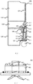
- FIG. 3 is a cross-sectional view of the refrigerator 101 of the present invention taken along the line A-A in FIG. 2 . The internal structure of the refrigerator 101 will be described with reference to FIGS. 2 and 3 .
- the refrigerator main body 1201 has: a refrigerating chamber 1203 into which cold air for refrigeration is sent, a refrigerating chamber 1207 for storing foods to be refrigerated, a vegetable compartment 1209, and a freezing chamber 1205 into which cold air is sent for freezing.
- the freezing chamber 1205 is provided in the lowermost portion
- the vegetable compartment 1209 is provided above the freezing chamber 1205
- the refrigerating chamber 1207 for storing foods to be refrigerated is provided above the vegetable compartment 1209.
- a machine room 301 is disposed on the back of the freezing chamber 1205, and a compressor is disposed in a lower portion of the machine room 301.
- a heater 311 is disposed above the machine room 301 on the back of the freezing chamber.
- An evaporator 303 serving as a cooler is disposed above the heater 311 on the back of the freezing chamber.
- the machine room 301 is disposed in a lower portion of the refrigerator 101. However, this portion takes up the volume of the storage chamber of the refrigerator 101.
- the freezing chamber 1205 is disposed in the lowest portion of the refrigerator 101, so the machine room 301 will take up the volume of the freezing chamber 1205.
- the evaporator 303 generates cold air for cooling the freezing chamber 1205 and the refrigerating chamber 1203.
- the evaporator 303 which is disposed on the back side of the freezing chamber and above the machine room 301 is set to be vertically elongated.
- the vertically elongated evaporator 303 can have a longer cooling area, so the cooling efficiency is high.
- the heater 311 is disposed below the evaporator 303 to remove the frost adhered to the evaporator 303.
- the heater 311 will automatically start after a certain period of time has passed to warm the air and melt the frost.
- the melted frost becomes water and is discharged from the lower portion of the heater 311.
- a fan 305 is disposed on the evaporator 303 on the back of the freezing chamber.
- the fan 305 can at least make cold air flow into the freezing chamber 1205. After passing through the fan 305, the cold air flows towards the freezing chamber 1205 through an air duct 315, through an air outlet 319 corresponding to air outlets 211, 213 in FIG. 2 , an air outlet 321 corresponding to air outlets 215, 217 in FIG. 2 , and an air outlet 323 corresponding to the air outlet 219 in FIG. 2 .
- the cold air after circulating in the freezing chamber 1205, is sucked in through an air return port 325 corresponding to an air return port 221 in FIG. 2 , and is cooled in the evaporator 303 again.
- cold air flows into the refrigerating chamber 1203 through an air throttle 313, and the air throttle 313 switches the inflow into the refrigerating chamber 1203.
- the cold air After passing through the air throttle 313, the cold air enters the air duct 317, and flows towards the refrigerating chamber 1203 through an air outlet 227 in FIG. 2 , an air outlet 329 corresponding to an air outlet 229 in FIG. 2 , and an air outlet 331 corresponding to the air outlet 231 in FIG. 2 .
- the cold air after circulating in the refrigerating chamber 1203, is sucked in from the air return ports 223 and 225, passes through a return air duct, returns to a lower side of the evaporator 303, and is cooled again in the evaporator 303.
- the freezing chamber 1205 and the refrigerating chamber 1203 are partitioned by an intermediate separator plate 307.
- the intermediate separator plate 307 bends the inside of the freezing chamber 1205 upward on the back side of the freezing chamber 1205 to create a space 309 for the freezing chamber 1205.
- At least one portion of the fan 305 is disposed in the space 309.
- the intermediate separator plate 307 may bend upward on the back side of the freezing chamber 1205 to form the space 309 as in the present embodiment, it is also possible to remove a portion of the intermediate separator plate 307 to form the space 309.
- the space on the back side of the freezing chamber 1205 can be effectively used with the fan 305 being disposed in the space 309. Therefore, the volume of the freezing chamber 1205 can be made larger.
- the vegetable compartment 1209 is disposed below the refrigerating chamber 1203 and directly above the intermediate separator plate 307.
- the space 309 can be a portion of the vegetable compartment 1209, or can make an unnecessary portion of the vegetable compartment 1209 become a portion of the freezing chamber 1205.
- a dead space of a portion of the air duct 315 can be set as a portion of the freezing chamber 1205.
- the refrigerator of the present invention increases the volume of the freezing chamber 1205 with the fan 305 not occupying the volume of the freezing chamber 1205.
- the present invention can reduce the volume of the vegetable compartment 1209 and increase the volume of the freezing chamber 1205.
- the volume of the air duct 315 is reduced, and the volume of the freezing chamber 1205 is increased.
- a site for disposing the evaporator 303 which is on the back of the freezing chamber and disposed above the machine room 301 can be set in an upper direction. Therefore, it is possible to arrange the evaporator 303 to be vertically elongated, enhance the cooling efficiency, and increase the volume of the back side of the freezing chamber.
- FIG. 4 is a schematic diagram of a portion, namely, a fan and a fan cover, of a fan shielding device according to the present invention.
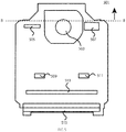
- FIG. 5 is a front view of the fan shielding device according to the present invention. The fan shielding device including the fan and the fan cover will be described with reference to FIG. 4 and FIG. 5 .
- FIG. 4 shows a portion 401 of the fan shielding device including the fan 403 and the fan cover 405.
- the fan cover 405 coaxial with a central shaft of the fan 403 shown by the dashed line in FIG. 4 and the fan shielding device are attached.
- the fan cover 405 assumes a shape of a cover with an internal thread 407, and the fan 403 is mounted on the fan shielding device.
- the fan cover 405 moves up and down by the rotation of a shaft portion 409, and the shaft portion 409 is located above the fan 403, is coaxial with the central shaft of the fan 403 and is engaged with the internal thread 407.
- the support pin 411 runs through the fan cover 405 for guiding, so that the fan cover 405 moves in parallel.
- the fan cover 405 opens when it acts upward, and the cooling space cooled by the evaporator 303 communicates with the space of the air duct 315, so that air flows in the direction indicated by the arrows.
- the fan cover 405 closes when it acts downward, and communication between the cooling space cooled by the evaporator 303 and the air duct 315 is blocked.
- the fan cover 405 can shield the fan 403 during the defrosting period when the heater 311 of the evaporator 303 is turned on. During the defrosting period, the heater 311 is activated to melt the frost. At the same time, the fan 403 is shielded by closing the fan cover 405, and then communication between the cooling space and the space of air duct 315 is blocked, so that it will not occur that the warm air in the refrigerator flows around and the temperature rises.
- the present invention may achieve the effect of power saving.
- FIG. 5 is a front view of the fan shielding device 501.
- the fan shielding device 501 comprises a fan 403 corresponding to the fan 305 in FIG. 3 and a fan cover 405, the air duct 315 in FIG. 3 , air outlets 505, 507 corresponding to the air outlets 211, 213 in FIG. 2 and corresponding to the air outlet 319 in FIG. 3 , air outlets 509, 511 corresponding to the air outlets 215, 217 in FIG. 2 and corresponding to the air outlet 321 in FIG. 3 , an air outlet 513 corresponding to the air outlet 219 in FIG. 2 and corresponding to the air outlet 323 in FIG. 3 , and an air return port 515 corresponding to the air return port 221 in FIG. 2 and corresponding to the air return port 325 in FIG. 3 .
- the space 309 is provided with a portion above than the line B-B of the fan shielding device 501.
- the portion 401 of the fan shielding device is disposed on the back of a position 503 of the fan shielding device 501. In this way, the portion of the fan shielding device 501 including the fan 403 and the fan cover 405 is disposed in the space 309.
- the air outlet 505 and the air outlet 507 are provided in parallel with the position 503 where the fan 403 is provided.
- the cold air needs to be sent from the vicinity of the ceiling of the freezing chamber 1205.
- an air outlet is disposed above the position of the fan.
- the fan 403 can be disposed above the freezing chamber 1205, so the air outlet 505 for blowing air can be placed in parallel with the position 503 where the fan 403 is disposed. In this way, the cold air can be sent to the freezing chamber 1205 with a high air flow rate, and therefore, power can be saved.
- the volume of the freezing chamber 1205 can be increased in the refrigerator provided with the fan shielding device.
- the present invention can provide a power-saving refrigerator by providing the fan shielding device.
- the present invention can provide a refrigerator with a high cooling efficiency and increased volume of the freezing chamber 1205 by disposing the vertically elongated evaporator 303 on the back of the freezing chamber.
- the present invention can be applied to a refrigerator with a fan disposed on the back of the freezing chamber.
- the present invention can be applied to a refrigerator provided with a fan shielding device for saving power.
Landscapes
- Engineering & Computer Science (AREA)
- Chemical & Material Sciences (AREA)
- Combustion & Propulsion (AREA)
- Physics & Mathematics (AREA)
- Mechanical Engineering (AREA)
- Thermal Sciences (AREA)
- General Engineering & Computer Science (AREA)
- Cold Air Circulating Systems And Constructional Details In Refrigerators (AREA)
- Defrosting Systems (AREA)
- Devices That Are Associated With Refrigeration Equipment (AREA)
Abstract
Description
- The present invention relates to a refrigerator having a freezing chamber and a refrigerating chamber.
- A practice arises in recent years: cutting vegetable and then storing it in a freezing chamber, and taking the vegetable out of the freezing chamber upon cooking the vegetable. Therefore, there is a requirement for reducing the volume of vegetable compartment and increasing the volume of the freezing chamber.
- In addition, patent document 1 discloses the following technique: adding a fan cover to a fan which feeds cold air to the freezing chamber and refrigerating chamber to save electrical power. The fan cover is closed and a heater is on during defrosting, so that warm air does not flow in the refrigerator.
- Patent document 1:
Japanese patent No. 6254404 - The fan and a fan shielding cover provided with a fan cover are disposed on a back side of the freezing chamber. Therefore, the size of the fan shielding device takes up the volume of the freezing chamber. In addition, on the back side of the freezing chamber are disposed an evaporator serving as a cooler and a heater for defrosting purpose. If the freezing chamber is disposed at the lowermost portion of the refrigerator, a machine room disposed in the lower portion of the refrigerator and provided with a compressor will takes up the space for disposing the evaporator and the heater, so that the volume of the freezing chamber becomes smaller.
- In view of the above, it is necessary to improve the conventional refrigerators to solve the above problems.
- An object of the present invention is to provide a refrigerator which is provided with a fan shielding device and has an increased volume of the freezing chamber
- Another object of the present invention is to provide a power-saving refrigerator by providing a fan shielding device. In addition, the refrigerator according to the present invention may also improve the cooling efficiency by disposing the vertically elongated evaporator on the back of the freezing chamber.
- To achieve the above-mentioned objects, the present invention provides a refrigerator comprising: a freezing chamber; a refrigerating chamber disposed above the freezing chamber; and a fan disposed on a back side of the freezing chamber and above an evaporator, so that the fan can at least make cold air flow into the freezing chamber through an air duct and through an air outlet, an intermediate separator plate between the freezing chamber and the refrigerating chamber is on a back side of the freezing chamber so that an inner side of the freezing chamber bends upward to create a space for the freezing chamber, and at least a portion of the fan is disposed in the space.
- As such, the refrigerator according to the present invention is provided with a fan in the space, which can increase the volume of the freezing chamber. In addition, the present invention can provide a power-saving refrigerator by providing a fan shielding device. Furthermore, in the refrigerator according to the present invention, the cooling efficiency can be enhanced and the volume of the freezing chamber can be increased by setting a vertically elongated site for disposing the evaporator which is on the back of the freezing chamber and disposed above the machine room.
- As a further improvement of the present invention, an air outlet of the freezing chamber is disposed at a position parallel to the fan. As such, the cold air can be sent to the freezing chamber with a high air flow rate.
- As a further improvement of the present invention, a fan cover and a fan shielding device are provided coaxial with a central shaft of the fan, the fan cover assumes a shape of a cover with an internal thread, the fan is mounted on the fan shielding device, the fan cover opens and closes by the rotation of a shaft portion, the shaft portion is disposed above the fan, is coaxial with the central shaft of the fan and is engaged with the internal thread, a cooling space cooled by the evaporator communicates with a space of the air duct by opening the fan cover, and the communication between the cooling space and the space of the air duct is blocked by closing the fan cover.
- Thus, the fan cover can be opened and closed with a simple mechanism. The present invention can block the communication between the cooling space and the space of the air duct by providing the fan shielding device.
- As a further improvement of the present invention, a heater is disposed below the evaporator; during a defrosting period, the fan cover closes and blocks the communication between the cooling space and the space of the air duct, and the heater is activated to melt frost.
- Thus, in the refrigerator according to the present invention, the fan can be shielded during a defrosting period when the heater is turned on. With the fan being shielded, it will not occur that the warm air in the refrigerator flows around and the temperature rises. Thus, the present invention may achieve power saving.
- As a further improvement of the present invention, a vegetable compartment is disposed below the refrigerating chamber and directly above the intermediate separator plate. As such, the volume of the vegetable compartment can be reduced and the volume of the freezing chamber can be increased.
- Advantageous effects of the present invention are as follows: the refrigerator according to the present invention is provided with the fan shielding device, which can increase the volume of the freezing chamber. In addition, the present invention can provide a power-saving refrigerator with the fan shielding device being provided. Furthermore, a refrigerator with a high cooling efficiency and an increased volume of the freezing chamber can be provided by disposing a vertically elongated evaporator on the back side of the freezing chamber.
-
-
FIG. 1 is a schematic diagram of a refrigerator according to the present invention. -
FIG. 2 is a front view of the refrigerator whose door body is opened according to the present invention. -
FIG. 3 is a cross-sectional view of the refrigerator shown inFIG. 2 taken along the line A-A. -
FIG. 4 is a schematic diagram of a portion, namely, a fan and a fan cover, of a fan shielding device of the refrigerator according to the present invention. -
FIG. 5 is a front view of the fan shielding device of the refrigerator according to the present invention. -
- 101
- refrigerator
- 103
- refrigerator main body
- 105
- door body
- 107
- door body
- 1201
- refrigerator body
- 1203
- refrigerating chamber
- 1205
- freezing chamber
- 1207
- refrigerating chamber for storing food to be refrigerated
- 1209
- Vegetable compartment
- 211
- air outlet
- 213
- air outlet
- 215
- air outlet
- 217
- air outlet
- 219
- air outlet
- 221
- air return port
- 223
- air return port
- 225
- air return port
- 227
- air outlet
- 229
- air outlet
- 231
- air outlet
- 301
- machine room
- 303
- evaporator
- 305
- fan
- 307
- intermediate separator plate
- 309
- space
- 311
- heater
- 313
- air throttle
- 315
- air duct
- 317
- air duct
- 319
- air outlet
- 321
- air outlet
- 323
- air outlet
- 325
- air return port
- 329
- air outlet
- 331
- air outlet
- 401
- a portion of the fan shielding device
- 403
- fan
- 405
- fan cover
- 407
- internal thread
- 409
- shaft portion
- 411
- support pin
- 501
- fan shielding device
- 503
- position
- 505
- air outlet
- 507
- air outlet
- 509
- air outlet
- 511
- air outlet
- 513
- air outlet
- 515
- air return port.
- To make the objectives, technical solutions and advantages of the present invention clearer, the present invention will be described in detail below with reference to the figures and specific embodiments.
-
FIG. 1 is a schematic diagram of a refrigerator in a preferred embodiment of the present invention. The overall structure of the refrigerator of the present invention will be described below with reference toFIG. 1 . - As shown in
FIG. 1 , therefrigerator 101 according to the present invention comprises a refrigeratormain body 103 capable of storing food and the like therein. The refrigeratormain body 103 comprisesdoor bodies door body 105 opens and closes a refrigerating chamber, and thedoor body 107 opens and closes a freezingchamber 1205. -
FIG. 2 is a front view of the refrigerator whose door body is opened according to the present invention, the description of the door body being omitted here.FIG. 3 is a cross-sectional view of therefrigerator 101 of the present invention taken along the line A-A inFIG. 2 . The internal structure of therefrigerator 101 will be described with reference toFIGS. 2 and3 . - As shown in
FIG. 2 , the refrigeratormain body 1201 has: a refrigeratingchamber 1203 into which cold air for refrigeration is sent, a refrigeratingchamber 1207 for storing foods to be refrigerated, avegetable compartment 1209, and a freezingchamber 1205 into which cold air is sent for freezing. In the refrigeratormain body 1201, the freezingchamber 1205 is provided in the lowermost portion, thevegetable compartment 1209 is provided above the freezingchamber 1205, and therefrigerating chamber 1207 for storing foods to be refrigerated is provided above thevegetable compartment 1209. - As shown in
FIG. 3 , amachine room 301 is disposed on the back of the freezingchamber 1205, and a compressor is disposed in a lower portion of themachine room 301. Aheater 311 is disposed above themachine room 301 on the back of the freezing chamber. Anevaporator 303 serving as a cooler is disposed above theheater 311 on the back of the freezing chamber. - To lower the center of gravity of the
refrigerator 101 to stabilize the installation of therefrigerator 101, themachine room 301 is disposed in a lower portion of therefrigerator 101. However, this portion takes up the volume of the storage chamber of therefrigerator 101. In the present embodiment, the freezingchamber 1205 is disposed in the lowest portion of therefrigerator 101, so themachine room 301 will take up the volume of the freezingchamber 1205. - The
evaporator 303 generates cold air for cooling the freezingchamber 1205 and therefrigerating chamber 1203. In order to maintain the cooling capacity of therefrigerator 101 of the present invention, theevaporator 303 which is disposed on the back side of the freezing chamber and above themachine room 301 is set to be vertically elongated. The vertically elongatedevaporator 303 can have a longer cooling area, so the cooling efficiency is high. - The
heater 311 is disposed below theevaporator 303 to remove the frost adhered to theevaporator 303. Theheater 311 will automatically start after a certain period of time has passed to warm the air and melt the frost. The melted frost becomes water and is discharged from the lower portion of theheater 311. - A
fan 305 is disposed on theevaporator 303 on the back of the freezing chamber. Thefan 305 can at least make cold air flow into the freezingchamber 1205. After passing through thefan 305, the cold air flows towards the freezingchamber 1205 through anair duct 315, through anair outlet 319 corresponding to airoutlets FIG. 2 , anair outlet 321 corresponding to airoutlets FIG. 2 , and anair outlet 323 corresponding to theair outlet 219 inFIG. 2 . - The cold air, after circulating in the freezing
chamber 1205, is sucked in through anair return port 325 corresponding to anair return port 221 inFIG. 2 , and is cooled in theevaporator 303 again. - In addition, cold air flows into the refrigerating
chamber 1203 through anair throttle 313, and theair throttle 313 switches the inflow into the refrigeratingchamber 1203. After passing through theair throttle 313, the cold air enters theair duct 317, and flows towards the refrigeratingchamber 1203 through anair outlet 227 inFIG. 2 , anair outlet 329 corresponding to anair outlet 229 inFIG. 2 , and anair outlet 331 corresponding to theair outlet 231 inFIG. 2 . - The cold air, after circulating in the
refrigerating chamber 1203, is sucked in from theair return ports evaporator 303, and is cooled again in theevaporator 303. - The freezing
chamber 1205 and therefrigerating chamber 1203 are partitioned by anintermediate separator plate 307. Theintermediate separator plate 307 bends the inside of the freezingchamber 1205 upward on the back side of the freezingchamber 1205 to create aspace 309 for the freezingchamber 1205. At least one portion of thefan 305 is disposed in thespace 309. - Although the
intermediate separator plate 307 may bend upward on the back side of the freezingchamber 1205 to form thespace 309 as in the present embodiment, it is also possible to remove a portion of theintermediate separator plate 307 to form thespace 309. - The space on the back side of the freezing
chamber 1205 can be effectively used with thefan 305 being disposed in thespace 309. Therefore, the volume of the freezingchamber 1205 can be made larger. - The
vegetable compartment 1209 is disposed below the refrigeratingchamber 1203 and directly above theintermediate separator plate 307. Thespace 309 can be a portion of thevegetable compartment 1209, or can make an unnecessary portion of thevegetable compartment 1209 become a portion of the freezingchamber 1205. In addition, a dead space of a portion of theair duct 315 can be set as a portion of the freezingchamber 1205. - As such, the refrigerator of the present invention increases the volume of the freezing
chamber 1205 with thefan 305 not occupying the volume of the freezingchamber 1205. In addition, the present invention can reduce the volume of thevegetable compartment 1209 and increase the volume of the freezingchamber 1205. Furthermore, the volume of theair duct 315 is reduced, and the volume of the freezingchamber 1205 is increased. - In addition, in the refrigerator of the present invention, a site for disposing the
evaporator 303 which is on the back of the freezing chamber and disposed above themachine room 301, can be set in an upper direction. Therefore, it is possible to arrange theevaporator 303 to be vertically elongated, enhance the cooling efficiency, and increase the volume of the back side of the freezing chamber. -
FIG. 4 is a schematic diagram of a portion, namely, a fan and a fan cover, of a fan shielding device according to the present invention.FIG. 5 is a front view of the fan shielding device according to the present invention. The fan shielding device including the fan and the fan cover will be described with reference toFIG. 4 andFIG. 5 . -
FIG. 4 shows aportion 401 of the fan shielding device including thefan 403 and thefan cover 405. Thefan cover 405 coaxial with a central shaft of thefan 403 shown by the dashed line inFIG. 4 and the fan shielding device are attached. Thefan cover 405 assumes a shape of a cover with aninternal thread 407, and thefan 403 is mounted on the fan shielding device. - The
fan cover 405 moves up and down by the rotation of ashaft portion 409, and theshaft portion 409 is located above thefan 403, is coaxial with the central shaft of thefan 403 and is engaged with theinternal thread 407. Thesupport pin 411 runs through thefan cover 405 for guiding, so that thefan cover 405 moves in parallel. - The
fan cover 405 opens when it acts upward, and the cooling space cooled by theevaporator 303 communicates with the space of theair duct 315, so that air flows in the direction indicated by the arrows. Thefan cover 405 closes when it acts downward, and communication between the cooling space cooled by theevaporator 303 and theair duct 315 is blocked. - Therefore, the
fan cover 405 can shield thefan 403 during the defrosting period when theheater 311 of theevaporator 303 is turned on. During the defrosting period, theheater 311 is activated to melt the frost. At the same time, thefan 403 is shielded by closing thefan cover 405, and then communication between the cooling space and the space ofair duct 315 is blocked, so that it will not occur that the warm air in the refrigerator flows around and the temperature rises. Thus, the present invention may achieve the effect of power saving. -
FIG. 5 is a front view of thefan shielding device 501. Thefan shielding device 501 comprises afan 403 corresponding to thefan 305 inFIG. 3 and afan cover 405, theair duct 315 inFIG. 3 ,air outlets air outlets FIG. 2 and corresponding to theair outlet 319 inFIG. 3 ,air outlets air outlets FIG. 2 and corresponding to theair outlet 321 inFIG. 3 , anair outlet 513 corresponding to theair outlet 219 inFIG. 2 and corresponding to theair outlet 323 inFIG. 3 , and anair return port 515 corresponding to theair return port 221 inFIG. 2 and corresponding to theair return port 325 inFIG. 3 . - As shown in
FIG. 3 , thespace 309 is provided with a portion above than the line B-B of thefan shielding device 501. In addition, theportion 401 of the fan shielding device is disposed on the back of aposition 503 of thefan shielding device 501. In this way, the portion of thefan shielding device 501 including thefan 403 and thefan cover 405 is disposed in thespace 309. - Here, an important thing is that the
air outlet 505 and theair outlet 507 are provided in parallel with theposition 503 where thefan 403 is provided. The cold air needs to be sent from the vicinity of the ceiling of the freezingchamber 1205. In the prior art, an air outlet is disposed above the position of the fan. - However, in the present invention, the
fan 403 can be disposed above the freezingchamber 1205, so theair outlet 505 for blowing air can be placed in parallel with theposition 503 where thefan 403 is disposed. In this way, the cold air can be sent to the freezingchamber 1205 with a high air flow rate, and therefore, power can be saved. - According to the present invention, the volume of the freezing
chamber 1205 can be increased in the refrigerator provided with the fan shielding device. In addition, the present invention can provide a power-saving refrigerator by providing the fan shielding device. Furthermore, the present invention can provide a refrigerator with a high cooling efficiency and increased volume of the freezingchamber 1205 by disposing the vertically elongatedevaporator 303 on the back of the freezing chamber. - The present invention can be applied to a refrigerator with a fan disposed on the back of the freezing chamber. In addition, the present invention can be applied to a refrigerator provided with a fan shielding device for saving power.
- The above embodiments are only intended to illustrate the technical solutions of the present invention and not to limit them. Although the present invention has been described in detail with reference to the preferred embodiments, those having ordinary skill in the art should understand that the technical solutions of the present invention may be modified or equivalently replaced, without departing from the spirit and scope of the technical solutions of the present invention.
Claims (5)
- A refrigerator, comprising: a freezing chamber and a refrigerating chamber disposed above the freezing chamber, wherein the refrigerator further comprises:a fan disposed on a back side of the freezing chamber and above an evaporator, so that the fan can at least make cold air flow into the freezing chamber through a air duct and through an air outlet,an intermediate separator plate between the freezing chamber and the refrigerating chamber is on a back side of the freezing chamber so that an inner side of the freezing chamber bends upward to create a space for the freezing chamber, andat least a portion of the fan is disposed in the space.
- The refrigerator according to claim 1, wherein an air outlet of the freezing chamber is disposed at a position parallel to the fan.
- The refrigerator according to claim 1 or 2, wherein a fan cover and a fan shielding device are provided coaxial with a central shaft of the fan, the fan cover assumes a shape of a cover with an internal thread, the fan is mounted on the fan shielding device, the fan cover opens and closes by the rotation of a shaft portion, the shaft portion is disposed above the fan, is coaxial with the central shaft of the fan and is engaged with the internal thread, a cooling space cooled by the evaporator communicates with a space of the air duct by opening the fan cover, and the communication between the cooling space and the space of the air duct is blocked by closing the fan cover.
- The refrigerator according to claim 3, wherein a heater is disposed below the evaporator; during a defrosting period, the fan cover closes and blocks the communication between the cooling space and the space of the air duct, and the heater is activated to melt frost.
- The refrigerator according to claim 4, wherein a vegetable compartment is disposed below the refrigerating chamber and directly above the intermediate separator plate.
Applications Claiming Priority (2)
| Application Number | Priority Date | Filing Date | Title |
|---|---|---|---|
| JP2018233569A JP2020094753A (en) | 2018-12-13 | 2018-12-13 | refrigerator |
| PCT/CN2019/123352 WO2020119575A1 (en) | 2018-12-13 | 2019-12-05 | Refrigerator |
Publications (2)
| Publication Number | Publication Date |
|---|---|
| EP3896370A1 true EP3896370A1 (en) | 2021-10-20 |
| EP3896370A4 EP3896370A4 (en) | 2022-02-16 |
Family
ID=71075577
Family Applications (1)
| Application Number | Title | Priority Date | Filing Date |
|---|---|---|---|
| EP19896148.4A Withdrawn EP3896370A4 (en) | 2018-12-13 | 2019-12-05 | FRIDGE |
Country Status (4)
| Country | Link |
|---|---|
| EP (1) | EP3896370A4 (en) |
| JP (1) | JP2020094753A (en) |
| CN (1) | CN112243482A (en) |
| WO (1) | WO2020119575A1 (en) |
Families Citing this family (1)
| Publication number | Priority date | Publication date | Assignee | Title |
|---|---|---|---|---|
| CN119085217A (en) * | 2024-07-30 | 2024-12-06 | 合肥美的电冰箱有限公司 | Air duct module and horizontal refrigerator |
Family Cites Families (15)
| Publication number | Priority date | Publication date | Assignee | Title |
|---|---|---|---|---|
| JPH07101141B2 (en) * | 1989-03-14 | 1995-11-01 | シャープ株式会社 | Blower for refrigerator |
| JPH07294089A (en) * | 1994-04-19 | 1995-11-10 | Daewoo Electronics Co Ltd | Frost reduction device for refrigerator |
| JP2846602B2 (en) * | 1995-06-14 | 1999-01-13 | 株式会社日立製作所 | refrigerator |
| KR100498386B1 (en) * | 2002-12-06 | 2005-07-01 | 엘지전자 주식회사 | Apparatus for supply the cool air of refrigerator |
| KR100525401B1 (en) * | 2002-12-24 | 2005-11-02 | 엘지전자 주식회사 | refrigerator |
| JP4985833B2 (en) * | 2010-08-26 | 2012-07-25 | パナソニック株式会社 | Supercooling control refrigerator |
| CN102331138B (en) * | 2011-09-22 | 2013-11-06 | 海信容声(广东)冰箱有限公司 | Refrigerator air channel structure capable of synchronously adjusting refrigeration and freezing |
| JP6145684B2 (en) * | 2012-03-06 | 2017-06-14 | パナソニックIpマネジメント株式会社 | refrigerator |
| JP6254404B2 (en) * | 2013-09-24 | 2017-12-27 | アクア株式会社 | Shielding device and refrigerator having the same |
| JP2015209987A (en) * | 2014-04-24 | 2015-11-24 | パナソニックIpマネジメント株式会社 | Vegetable case and refrigerator |
| CN204187907U (en) * | 2014-09-17 | 2015-03-04 | 博西华电器(江苏)有限公司 | Refrigerator and the interface channel for this refrigerator |
| CN104748484A (en) * | 2015-04-21 | 2015-07-01 | 合肥华凌股份有限公司 | Air channel component and refrigeration device |
| CN205860628U (en) * | 2016-08-03 | 2017-01-04 | 海信(山东)冰箱有限公司 | A kind of freezing air channel and wind cooling refrigerator |
| JP6799853B2 (en) * | 2016-12-15 | 2020-12-16 | アクア株式会社 | refrigerator |
| CN116336720A (en) * | 2017-12-29 | 2023-06-27 | 青岛海尔电冰箱有限公司 | refrigerator |
-
2018
- 2018-12-13 JP JP2018233569A patent/JP2020094753A/en active Pending
-
2019
- 2019-12-05 WO PCT/CN2019/123352 patent/WO2020119575A1/en not_active Ceased
- 2019-12-05 CN CN201980028196.6A patent/CN112243482A/en active Pending
- 2019-12-05 EP EP19896148.4A patent/EP3896370A4/en not_active Withdrawn
Also Published As
| Publication number | Publication date |
|---|---|
| JP2020094753A (en) | 2020-06-18 |
| CN112243482A (en) | 2021-01-19 |
| WO2020119575A1 (en) | 2020-06-18 |
| EP3896370A4 (en) | 2022-02-16 |
Similar Documents
| Publication | Publication Date | Title |
|---|---|---|
| EP1642070B1 (en) | Refrigerator | |
| US8429926B2 (en) | Ice storage bin and icemaker apparatus for refrigerator | |
| US7458229B2 (en) | Refrigerator with intermediate temperature icemaking compartment | |
| KR101659622B1 (en) | Method for controlling of refrigerator | |
| EP3524907B1 (en) | Refrigerator | |
| JP5903552B2 (en) | refrigerator | |
| US9382909B2 (en) | Refrigerator having centrifugal fan-duct assembly | |
| KR20090046297A (en) | Food storage device | |
| EP3751221A1 (en) | Refrigeration air supply assembly | |
| CN102287986A (en) | Air cooling refrigerator and control method thereof | |
| EP2778577A1 (en) | Refrigerator | |
| EP4174412B1 (en) | Refrigerator having evaporator disposed at bottom of refrigerator body | |
| CN112082304B (en) | Refrigerating equipment | |
| EP4206572B1 (en) | Refrigerator | |
| EP3896370A1 (en) | Refrigerator | |
| JP3399880B2 (en) | refrigerator | |
| CN209893750U (en) | Quick-freezing air-cooling frostless refrigerator | |
| JP5895145B2 (en) | refrigerator | |
| JP3439981B2 (en) | refrigerator | |
| CN207197050U (en) | Refrigerator | |
| CN211552159U (en) | refrigerator | |
| CN110487010A (en) | A kind of wind cooling refrigerator | |
| JP2010071563A (en) | Refrigerator | |
| KR20100028828A (en) | A refrigerator | |
| JP2025079047A (en) | refrigerator |
Legal Events
| Date | Code | Title | Description |
|---|---|---|---|
| STAA | Information on the status of an ep patent application or granted ep patent |
Free format text: STATUS: THE INTERNATIONAL PUBLICATION HAS BEEN MADE |
|
| PUAI | Public reference made under article 153(3) epc to a published international application that has entered the european phase |
Free format text: ORIGINAL CODE: 0009012 |
|
| STAA | Information on the status of an ep patent application or granted ep patent |
Free format text: STATUS: REQUEST FOR EXAMINATION WAS MADE |
|
| 17P | Request for examination filed |
Effective date: 20210611 |
|
| AK | Designated contracting states |
Kind code of ref document: A1 Designated state(s): AL AT BE BG CH CY CZ DE DK EE ES FI FR GB GR HR HU IE IS IT LI LT LU LV MC MK MT NL NO PL PT RO RS SE SI SK SM TR |
|
| RIC1 | Information provided on ipc code assigned before grant |
Ipc: F25D 21/08 20060101ALN20220106BHEP Ipc: F25D 17/04 20060101ALN20220106BHEP Ipc: F25D 23/06 20060101ALI20220106BHEP Ipc: F25D 17/06 20060101AFI20220106BHEP |
|
| A4 | Supplementary search report drawn up and despatched |
Effective date: 20220113 |
|
| DAV | Request for validation of the european patent (deleted) | ||
| DAX | Request for extension of the european patent (deleted) | ||
| STAA | Information on the status of an ep patent application or granted ep patent |
Free format text: STATUS: EXAMINATION IS IN PROGRESS |
|
| 17Q | First examination report despatched |
Effective date: 20231006 |
|
| GRAP | Despatch of communication of intention to grant a patent |
Free format text: ORIGINAL CODE: EPIDOSNIGR1 |
|
| STAA | Information on the status of an ep patent application or granted ep patent |
Free format text: STATUS: GRANT OF PATENT IS INTENDED |
|
| INTG | Intention to grant announced |
Effective date: 20250512 |
|
| STAA | Information on the status of an ep patent application or granted ep patent |
Free format text: STATUS: THE APPLICATION IS DEEMED TO BE WITHDRAWN |
|
| 18D | Application deemed to be withdrawn |
Effective date: 20250913 |