EP3896332A1 - Led spotlight - Google Patents
Led spotlight Download PDFInfo
- Publication number
- EP3896332A1 EP3896332A1 EP20791064.7A EP20791064A EP3896332A1 EP 3896332 A1 EP3896332 A1 EP 3896332A1 EP 20791064 A EP20791064 A EP 20791064A EP 3896332 A1 EP3896332 A1 EP 3896332A1
- Authority
- EP
- European Patent Office
- Prior art keywords
- sensor module
- lighting body
- led floodlight
- waterproof
- light source
- Prior art date
- Legal status (The legal status is an assumption and is not a legal conclusion. Google has not performed a legal analysis and makes no representation as to the accuracy of the status listed.)
- Withdrawn
Links
Images


Classifications
-
- F—MECHANICAL ENGINEERING; LIGHTING; HEATING; WEAPONS; BLASTING
- F21—LIGHTING
- F21V—FUNCTIONAL FEATURES OR DETAILS OF LIGHTING DEVICES OR SYSTEMS THEREOF; STRUCTURAL COMBINATIONS OF LIGHTING DEVICES WITH OTHER ARTICLES, NOT OTHERWISE PROVIDED FOR
- F21V31/00—Gas-tight or water-tight arrangements
- F21V31/005—Sealing arrangements therefor
-
- F—MECHANICAL ENGINEERING; LIGHTING; HEATING; WEAPONS; BLASTING
- F21—LIGHTING
- F21S—NON-PORTABLE LIGHTING DEVICES; SYSTEMS THEREOF; VEHICLE LIGHTING DEVICES SPECIALLY ADAPTED FOR VEHICLE EXTERIORS
- F21S8/00—Lighting devices intended for fixed installation
- F21S8/03—Lighting devices intended for fixed installation of surface-mounted type
- F21S8/033—Lighting devices intended for fixed installation of surface-mounted type the surface being a wall or like vertical structure, e.g. building facade
- F21S8/036—Lighting devices intended for fixed installation of surface-mounted type the surface being a wall or like vertical structure, e.g. building facade by means of a rigid support, e.g. bracket or arm
-
- F—MECHANICAL ENGINEERING; LIGHTING; HEATING; WEAPONS; BLASTING
- F21—LIGHTING
- F21V—FUNCTIONAL FEATURES OR DETAILS OF LIGHTING DEVICES OR SYSTEMS THEREOF; STRUCTURAL COMBINATIONS OF LIGHTING DEVICES WITH OTHER ARTICLES, NOT OTHERWISE PROVIDED FOR
- F21V17/00—Fastening of component parts of lighting devices, e.g. shades, globes, refractors, reflectors, filters, screens, grids or protective cages
- F21V17/002—Fastening of component parts of lighting devices, e.g. shades, globes, refractors, reflectors, filters, screens, grids or protective cages with provision for interchangeability, i.e. component parts being especially adapted to be replaced by another part with the same or a different function
-
- F—MECHANICAL ENGINEERING; LIGHTING; HEATING; WEAPONS; BLASTING
- F21—LIGHTING
- F21V—FUNCTIONAL FEATURES OR DETAILS OF LIGHTING DEVICES OR SYSTEMS THEREOF; STRUCTURAL COMBINATIONS OF LIGHTING DEVICES WITH OTHER ARTICLES, NOT OTHERWISE PROVIDED FOR
- F21V23/00—Arrangement of electric circuit elements in or on lighting devices
- F21V23/04—Arrangement of electric circuit elements in or on lighting devices the elements being switches
- F21V23/0442—Arrangement of electric circuit elements in or on lighting devices the elements being switches activated by means of a sensor, e.g. motion or photodetectors
-
- F—MECHANICAL ENGINEERING; LIGHTING; HEATING; WEAPONS; BLASTING
- F21—LIGHTING
- F21Y—INDEXING SCHEME ASSOCIATED WITH SUBCLASSES F21K, F21L, F21S and F21V, RELATING TO THE FORM OR THE KIND OF THE LIGHT SOURCES OR OF THE COLOUR OF THE LIGHT EMITTED
- F21Y2105/00—Planar light sources
- F21Y2105/10—Planar light sources comprising a two-dimensional array of point-like light-generating elements
- F21Y2105/14—Planar light sources comprising a two-dimensional array of point-like light-generating elements characterised by the overall shape of the two-dimensional array
- F21Y2105/16—Planar light sources comprising a two-dimensional array of point-like light-generating elements characterised by the overall shape of the two-dimensional array square or rectangular, e.g. for light panels
-
- F—MECHANICAL ENGINEERING; LIGHTING; HEATING; WEAPONS; BLASTING
- F21—LIGHTING
- F21Y—INDEXING SCHEME ASSOCIATED WITH SUBCLASSES F21K, F21L, F21S and F21V, RELATING TO THE FORM OR THE KIND OF THE LIGHT SOURCES OR OF THE COLOUR OF THE LIGHT EMITTED
- F21Y2115/00—Light-generating elements of semiconductor light sources
- F21Y2115/10—Light-emitting diodes [LED]
Definitions
- the present invention relates to an LED lighting apparatus, in particular to an LED floodlight.
- the LED lighting apparatus has been taken as an illumination light source or a lamp.
- the floodlight is a kind of the existing LED lighting apparatus.
- the sensor module of the existing LED inductor floodlights is generally arranged inside the lighting apparatus.
- An internal wiring is generally adopted, and the sensor module cannot serve as an independent optional device, also the sensor module and the power supply module cannot be separated completely. Therefore, the reliability is reduced, and the maintenance is troublesome. If any part is out of function, the whole lighting apparatus has to be replaced, which causes high use cost.
- the sensor module of some existing LED inductor floodlights is arranged outside the lighting apparatus, which means it is separated from the lighting apparatus, and waterproof joints are adopted to connect the external wiring with the induction module.
- This kind of the LED lighting apparatus has a discordant and abrupt appearance and is inconvenient to install and use.
- an existing LED lighting apparatus is generally provided with a waterproof rubber ring and a plurality of locking screw to realize water prevention of the panel, which causes time consuming working hours during manufacture and assembly, and is troublesome in terms of disassembly.
- the present invention intends to overcome deficiencies of the prior art and to provide an LED floodlight which is easy to mount, to replace and to maintain, and can be optionally provided with an independent sensor, and is easy to stock and prepare.
- the present invention adopts the following technical solutions:
- the invention comprises a lighting body being internally provided with a drive light source plate provided with LEDs, further comprises a mounting bracket and a sensor module being detachably assembled with the lighting body via a waterproof connector.
- the sensor module is electrically connected to the drive light source plate.
- the electric wires connecting the sensor module and the drive light source plate are passing through the waterproof connector.
- the overall shape of the sensor module and the lighting body after being assembled is rectangular.
- the sensor module is provided with a power line. The said power line is sealed to the sensor module via a waterproof bolt, so that the sensor module is waterproof.
- a light-transmitting plate and a reflector are arranged in the light emitting position of the drive light source plate inside the lighting body.
- the LED floodlight of the present invention comprises a plurality of elastic buckles, and a plurality of embedding holes are arranged on the lighting body.
- the plurality of elastic buckles passing through the plurality of embedding holes are clamped on the lighting body on the back surface, and the light-transmitting plate is tightly clamped on the lighting body on the front side thereof.
- each of the elastic buckles is provided with a reverse hook in order to be clamped on the back surface of the lighting body to prevent slippage.
- a waterproof sealing ring is arranged at the joint between the light-transmitting plate and the lighting body.
- a plurality of heat dissipation fins are arranged on the back surface of the lighting body.
- two supporting legs are respectively arranged on both sides of the mounting bracket to be connected with the lighting body by two bolts, wherein the supporting legs are rotatably positioned with the lighting body by taking the bolt as a shaft
- the present invention has advantageous effects as below because the present invention comprises a lighting body being internally provided with a drive light source plate provided with LEDs, a mounting bracket and a sensor module being detachably assembled with the lighting body via a waterproof connector, the sensor module is electrically connected to the drive light source plate, the electric wires connecting the sensor module and the drive light source plate are passing through the waterproof connector, the overall shape of the sensor module and the lighting body after being assembled is rectangular, the sensor module is provided with a power line, and the power line is sealed to the sensor module via a waterproof bolt, so that the sensor module is waterproof.
- the waterproof connector being detachably connected with the lighting body, the waterproof problem of the outdoor product is solved, and the sensor module is provided as an independent optional module.
- the invention enables independent modular production, and is convenient to assemble, furthermore the overall appearance is not discordant or abrupt when the sensor module is assembled with the lighting body as a whole, so that the customers can conveniently mount, replace and maintain the lighting apparatus and select combination for it, and for the manufacturers it is convenient to stock and prepare.
- This invention herein is easy to mount, to replace and to maintain, can be optionally provided with an independent sensor, and is easy to stock and prepare.
- an embodiment of the LED floodlight comprises a lighting body 1, a mounting bracket 2 and a sensor module 3, two supporting legs are respectively arranged on both sides of the mounting bracket 2 to be connected with the lighting body 1 by two bolts 13, the supporting legs are rotatably positioned with the lighting body 1 by taking the bolt 13 as a shaft, so that it can be conveniently assembled and connected, and the light emitting direction can be conveniently adjusted, the lighting body 1 is internally provided with a drive light source plate 5 provided with LEDs 4, the sensor module 3 is detachably assembled with the lighting body 1 via a waterproof connector 15.
- the sensor module 3 is electrically connected to the drive light source plate 5, the electric wires connecting the sensor module 3 and the drive light source plate 5 are passing through the waterproof connector 15.
- the overall shape of the sensor module 3 and the lighting body 1 after being assembled is rectangular.
- the sensor module 3 is provided with a power line 10, and the power line 10 is sealed to the sensor module 3 via a waterproof bolt 9, so that the sensor module 3 is waterproof.
- a light-transmitting plate 6 and a reflector 7 are arranged in the light emitting position of the drive light source plate 5 inside the lighting body 1.
- the LED floodlight further comprises four elastic buckles 8, and four embedding holes 12 are arranged on the lighting body 1.
- the four elastic buckles 8 respectively passing through the four embedding holes 12 are clamped on the lighting body 1 on the back surface, and the light-transmitting plate 6 is tightly clamped on the lighting body 1 on the front side thereof.
- Each of the elastic buckles 8 is provided with a reverse hook 81 to be clamped on the back surface of the lighting body 1 to prevent slippage.
- a waterproof sealing ring 14 is arranged at the joint between the light-transmitting plate 6 and the lighting body 1.
- a special spring buckle design is adopted, it could be firmly pressed against the light-transmitting plate 6 and the waterproof sealing ring 14 by matching with the structure of the lighting body 1, so as to reach the purpose of waterproofing.
- the buckles 8 have an anti-loosening function, that means it can be dismantled only with the help of tools, which leads to reduction of material costs of the product and reduction of production and assembling working hours.
- a plurality of heat dissipation fins 11 are arranged on the back surface of the lighting body 1, it brings heat dissipation well under the condition of the small size of the product.
- the waterproof connector 15 being detachably connected with the lighting body 1, the waterproof problem of the outdoor product is solved, and the sensor module is provided as an independent optional module.
- the invention enables independent modular production, and is convenient to assemble, furthermore the overall appearance is not discordant or abrupt when the sensor module 3 is assembled with the lighting body 1 as a whole, so that the customers can conveniently mount, replace and maintain the lighting apparatus and select combination for it, and for the manufacturers it is convenient to stock and prepare.
- This invention herein is easy to mount, to replace and to maintain, can be optionally provided with an independent sensor, and is easy to stock and prepare.
- the present invention can be widely applied in the field of LED floodlights.
Abstract
Description
- The present invention relates to an LED lighting apparatus, in particular to an LED floodlight.
- With the development of science and technology, the application of the LED lighting apparatus is increasingly wide, and the LED lighting apparatus has been taken as an illumination light source or a lamp. The floodlight is a kind of the existing LED lighting apparatus. And the sensor module of the existing LED inductor floodlights is generally arranged inside the lighting apparatus. An internal wiring is generally adopted, and the sensor module cannot serve as an independent optional device, also the sensor module and the power supply module cannot be separated completely. Therefore, the reliability is reduced, and the maintenance is troublesome. If any part is out of function, the whole lighting apparatus has to be replaced, which causes high use cost. In some other solutions in the prior art the sensor module of some existing LED inductor floodlights is arranged outside the lighting apparatus, which means it is separated from the lighting apparatus, and waterproof joints are adopted to connect the external wiring with the induction module. This kind of the LED lighting apparatus has a discordant and abrupt appearance and is inconvenient to install and use.
- In addition, an existing LED lighting apparatus is generally provided with a waterproof rubber ring and a plurality of locking screw to realize water prevention of the panel, which causes time consuming working hours during manufacture and assembly, and is troublesome in terms of disassembly.
- The present invention intends to overcome deficiencies of the prior art and to provide an LED floodlight which is easy to mount, to replace and to maintain, and can be optionally provided with an independent sensor, and is easy to stock and prepare.
- The present invention adopts the following technical solutions: The invention comprises a lighting body being internally provided with a drive light source plate provided with LEDs, further comprises a mounting bracket and a sensor module being detachably assembled with the lighting body via a waterproof connector. The sensor module is electrically connected to the drive light source plate. The electric wires connecting the sensor module and the drive light source plate are passing through the waterproof connector. The overall shape of the sensor module and the lighting body after being assembled is rectangular. The sensor module is provided with a power line. The said power line is sealed to the sensor module via a waterproof bolt, so that the sensor module is waterproof.
- Preferably, a light-transmitting plate and a reflector are arranged in the light emitting position of the drive light source plate inside the lighting body.
- Furthermore, the LED floodlight of the present invention comprises a plurality of elastic buckles, and a plurality of embedding holes are arranged on the lighting body. The plurality of elastic buckles passing through the plurality of embedding holes are clamped on the lighting body on the back surface, and the light-transmitting plate is tightly clamped on the lighting body on the front side thereof.
- Preferably, each of the elastic buckles is provided with a reverse hook in order to be clamped on the back surface of the lighting body to prevent slippage.
- Preferably, a waterproof sealing ring is arranged at the joint between the light-transmitting plate and the lighting body.
- Preferably, a plurality of heat dissipation fins are arranged on the back surface of the lighting body.
- Preferably, two supporting legs are respectively arranged on both sides of the mounting bracket to be connected with the lighting body by two bolts, wherein the supporting legs are rotatably positioned with the lighting body by taking the bolt as a shaft
- The present invention has advantageous effects as below because the present invention comprises a lighting body being internally provided with a drive light source plate provided with LEDs, a mounting bracket and a sensor module being detachably assembled with the lighting body via a waterproof connector, the sensor module is electrically connected to the drive light source plate, the electric wires connecting the sensor module and the drive light source plate are passing through the waterproof connector, the overall shape of the sensor module and the lighting body after being assembled is rectangular, the sensor module is provided with a power line, and the power line is sealed to the sensor module via a waterproof bolt, so that the sensor module is waterproof.
- With the waterproof connector being detachably connected with the lighting body, the waterproof problem of the outdoor product is solved, and the sensor module is provided as an independent optional module. The invention enables independent modular production, and is convenient to assemble, furthermore the overall appearance is not discordant or abrupt when the sensor module is assembled with the lighting body as a whole, so that the customers can conveniently mount, replace and maintain the lighting apparatus and select combination for it, and for the manufacturers it is convenient to stock and prepare. This invention herein is easy to mount, to replace and to maintain, can be optionally provided with an independent sensor, and is easy to stock and prepare.
-
-
Figure 1 is a perspective view from the frontside of a embodiment of the present invention; -
Figure 2 is a perspective view from the backside of the embodiment; -
Figure 3 is an exploded view of the embodiment; -
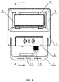
Figure 4 is a front view of the embodiment; and -
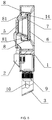
Figure 5 is a cross-section view of A-A inFigure 4 of the embodiment. - As shown on
Figure 1 to Figure 5 , an embodiment of the LED floodlight according to the present invention comprises alighting body 1, amounting bracket 2 and asensor module 3, two supporting legs are respectively arranged on both sides of themounting bracket 2 to be connected with thelighting body 1 by twobolts 13, the supporting legs are rotatably positioned with thelighting body 1 by taking thebolt 13 as a shaft, so that it can be conveniently assembled and connected, and the light emitting direction can be conveniently adjusted, thelighting body 1 is internally provided with a drivelight source plate 5 provided withLEDs 4, thesensor module 3 is detachably assembled with thelighting body 1 via awaterproof connector 15. Thesensor module 3 is electrically connected to the drivelight source plate 5, the electric wires connecting thesensor module 3 and the drivelight source plate 5 are passing through thewaterproof connector 15. The overall shape of thesensor module 3 and thelighting body 1 after being assembled is rectangular. Thesensor module 3 is provided with apower line 10, and thepower line 10 is sealed to thesensor module 3 via awaterproof bolt 9, so that thesensor module 3 is waterproof. A light-transmittingplate 6 and areflector 7 are arranged in the light emitting position of the drivelight source plate 5 inside thelighting body 1. The LED floodlight further comprises fourelastic buckles 8, and four embeddingholes 12 are arranged on thelighting body 1. The fourelastic buckles 8 respectively passing through the four embeddingholes 12 are clamped on thelighting body 1 on the back surface, and the light-transmittingplate 6 is tightly clamped on thelighting body 1 on the front side thereof. Each of theelastic buckles 8 is provided with areverse hook 81 to be clamped on the back surface of thelighting body 1 to prevent slippage. Awaterproof sealing ring 14 is arranged at the joint between the light-transmittingplate 6 and thelighting body 1. A special spring buckle design is adopted, it could be firmly pressed against the light-transmittingplate 6 and thewaterproof sealing ring 14 by matching with the structure of thelighting body 1, so as to reach the purpose of waterproofing. In addition, thebuckles 8 have an anti-loosening function, that means it can be dismantled only with the help of tools, which leads to reduction of material costs of the product and reduction of production and assembling working hours. A plurality ofheat dissipation fins 11 are arranged on the back surface of thelighting body 1, it brings heat dissipation well under the condition of the small size of the product. By means of the multi-position waterproof design of the present invention, the waterproof level of the outdoor lamp of the IPX 6 level is fulfilled . - With the
waterproof connector 15 being detachably connected with thelighting body 1, the waterproof problem of the outdoor product is solved, and the sensor module is provided as an independent optional module. The invention enables independent modular production, and is convenient to assemble, furthermore the overall appearance is not discordant or abrupt when thesensor module 3 is assembled with thelighting body 1 as a whole, so that the customers can conveniently mount, replace and maintain the lighting apparatus and select combination for it, and for the manufacturers it is convenient to stock and prepare. This invention herein is easy to mount, to replace and to maintain, can be optionally provided with an independent sensor, and is easy to stock and prepare. - The present invention can be widely applied in the field of LED floodlights.
Claims (7)
- An LED floodlight comprising a lighting body (1) being internally provided with a drive light source plate (5) provided with LEDs (4), wherein the LED floodlight further comprises a mounting bracket (2), characterized in that
the LED floodlight comprises a sensor module (3) being detachably assembled with the lighting body (1) via a waterproof connector (15), wherein the sensor module (3) is electrically connected to the drive light source plate (5), the electric wires connecting the sensor module (3) and the drive light source plate (5) are passing through the waterproof connector (15), wherein the overall shape of the sensor module (3) and the lighting body (1) after being assembled is rectangular, wherein the sensor module (3) is provided with a power line (10), and the power line (10) is sealed to the sensor module (3) via a waterproof bolt (9), so that the sensor module (3) is waterproof. - The LED floodlight according to claim 1, wherein a light-transmitting plate (6) and a reflector (7) are arranged in the light emitting position of the drive light source plate (5) inside the lighting body (1).
- The LED floodlight according to claim 2, wherein a plurality of elastic buckles (8) and a plurality of embedding holes (12) are arranged on the lighting body (1), wherein the plurality of elastic buckles (8) passing through the plurality of embedding holes (12) are clamped on the lighting body (1) on the back surface, and the light-transmitting plate (6) is tightly clamped on the lighting body (1) on the front side thereof.
- The LED floodlight according to claim 3, wherein each of the elastic buckles (8) is provided with a reverse hook (81) to be clamped on the back surface of the lighting body (1) to prevent slippage.
- An LED floodlight according to claim 3 or claim 4, wherein a waterproof sealing ring (14) is arranged at the joint between the light-transmitting plate (6) and the lighting body (1) .
- The LED floodlight according to claim 1, wherein a plurality of heat dissipation fins (11) are arranged on the back surface of the lighting body (1) .
- The LED floodlight according to claim 1, wherein two supporting legs are respectively arranged on both sides of the mounting bracket (2) to be connected with the lighting body (1) by two bolts (13), wherein the supporting legs are rotatably positioned with the lighting body (1) by taking the bolt (13) as a shaft.
Applications Claiming Priority (2)
| Application Number | Priority Date | Filing Date | Title |
|---|---|---|---|
| CN201920520531.1U CN209484394U (en) | 2019-04-17 | 2019-04-17 | A kind of LED projector lamp |
| PCT/CN2020/089902 WO2020211877A1 (en) | 2019-04-17 | 2020-05-13 | Led spotlight |
Publications (2)
| Publication Number | Publication Date |
|---|---|
| EP3896332A1 true EP3896332A1 (en) | 2021-10-20 |
| EP3896332A4 EP3896332A4 (en) | 2022-07-06 |
Family
ID=68135354
Family Applications (1)
| Application Number | Title | Priority Date | Filing Date |
|---|---|---|---|
| EP20791064.7A Withdrawn EP3896332A4 (en) | 2019-04-17 | 2020-05-13 | Led spotlight |
Country Status (3)
| Country | Link |
|---|---|
| EP (1) | EP3896332A4 (en) |
| CN (1) | CN209484394U (en) |
| WO (1) | WO2020211877A1 (en) |
Families Citing this family (1)
| Publication number | Priority date | Publication date | Assignee | Title |
|---|---|---|---|---|
| CN209484394U (en) * | 2019-04-17 | 2019-10-11 | 深圳华唐锐照明电器有限公司 | A kind of LED projector lamp |
Family Cites Families (10)
| Publication number | Priority date | Publication date | Assignee | Title |
|---|---|---|---|---|
| JP2001272211A (en) * | 2000-03-23 | 2001-10-05 | Nippon Signal Co Ltd:The | Light projector/receiver and mounting bracket therefor |
| CN202040630U (en) * | 2011-05-13 | 2011-11-16 | 卢建乔 | Light-emitting diode (LED) induction lamp |
| US9625128B2 (en) * | 2015-06-03 | 2017-04-18 | Xiamen Pvtech Co., Ltd. | High power tri-proof LED lamp |
| CN205402467U (en) * | 2016-03-03 | 2016-07-27 | 宁波市佛兰德光电科技有限公司 | LED responds to projecting lamp |
| CN106195795A (en) * | 2016-08-29 | 2016-12-07 | 春迅电子(东莞)有限公司 | A kind of infrared induction reflection wall type LED lamp |
| CN206429958U (en) * | 2016-12-31 | 2017-08-22 | 江西众光照明科技有限公司 | A kind of Waterproof LED senses Projecting Lamp |
| CN207674214U (en) * | 2017-12-22 | 2018-07-31 | 宁波荣华照明科技有限公司 | A kind of induction Projecting Lamp |
| CN207921874U (en) * | 2018-01-17 | 2018-09-28 | 江西众光照明科技有限公司 | A kind of LED light induction Projecting Lamp |
| CN207975621U (en) * | 2018-03-01 | 2018-10-16 | 厦门市佳昱光光电有限公司 | A kind of infrared induction water proof and dust proof Projecting Lamp |
| CN209484394U (en) * | 2019-04-17 | 2019-10-11 | 深圳华唐锐照明电器有限公司 | A kind of LED projector lamp |
-
2019
- 2019-04-17 CN CN201920520531.1U patent/CN209484394U/en active Active
-
2020
- 2020-05-13 WO PCT/CN2020/089902 patent/WO2020211877A1/en unknown
- 2020-05-13 EP EP20791064.7A patent/EP3896332A4/en not_active Withdrawn
Also Published As
| Publication number | Publication date |
|---|---|
| WO2020211877A1 (en) | 2020-10-22 |
| EP3896332A4 (en) | 2022-07-06 |
| CN209484394U (en) | 2019-10-11 |
Similar Documents
| Publication | Publication Date | Title |
|---|---|---|
| AU2008293539B2 (en) | LED based hazardous location light with versatile mounting configurations | |
| US9995462B2 (en) | Circular LED optic and heat sink module | |
| EP2193309B1 (en) | Light fixture support system | |
| US8888315B2 (en) | Vapor-tight lighting fixture | |
| US8616730B2 (en) | Vapor-tight lighting fixture | |
| JP2011014317A (en) | Lighting body and lighting system | |
| KR100945420B1 (en) | Method for manufacturing flood lighting | |
| EP3896332A1 (en) | Led spotlight | |
| CN106352254B (en) | Modularized interchangeable LED light engine and lamp system | |
| WO2010130211A1 (en) | Led illumination device | |
| CN110925614A (en) | Convenient replacement formula LED lamps and lanterns | |
| CN110953507A (en) | General type lamps and lanterns, concatenation formula lamp body and projecting lamp | |
| CN215489545U (en) | Lamp set | |
| CN214948388U (en) | LED line lamp convenient to aggregate erection | |
| CN215112188U (en) | LED (light-emitting diode) mining lamp | |
| CN216280896U (en) | Novel industrial and mining lamp | |
| CN210831732U (en) | Mining lamp with variable light distribution | |
| CN214064716U (en) | Lamp and lens | |
| CN216744258U (en) | Intelligent projection lamp | |
| EP3492798A1 (en) | Outdoor lighting fixture | |
| CN218064600U (en) | Ceiling lamp easy to assemble and disassemble | |
| CN210345152U (en) | LED lamp convenient to disassemble and assemble for heat dissipation | |
| CN220269241U (en) | Spotlight | |
| CN210004342U (en) | LED lamp capable of adjusting angle | |
| CN210567804U (en) | LED iodine tungsten lamp |
Legal Events
| Date | Code | Title | Description |
|---|---|---|---|
| STAA | Information on the status of an ep patent application or granted ep patent |
Free format text: STATUS: THE INTERNATIONAL PUBLICATION HAS BEEN MADE |
|
| PUAI | Public reference made under article 153(3) epc to a published international application that has entered the european phase |
Free format text: ORIGINAL CODE: 0009012 |
|
| STAA | Information on the status of an ep patent application or granted ep patent |
Free format text: STATUS: REQUEST FOR EXAMINATION WAS MADE |
|
| 17P | Request for examination filed |
Effective date: 20210211 |
|
| AK | Designated contracting states |
Kind code of ref document: A1 Designated state(s): AL AT BE BG CH CY CZ DE DK EE ES FI FR GB GR HR HU IE IS IT LI LT LU LV MC MK MT NL NO PL PT RO RS SE SI SK SM TR |
|
| A4 | Supplementary search report drawn up and despatched |
Effective date: 20220603 |
|
| RIC1 | Information provided on ipc code assigned before grant |
Ipc: F21Y 115/10 20160101ALI20220530BHEP Ipc: F21V 23/06 20060101ALI20220530BHEP Ipc: F21V 31/00 20060101ALI20220530BHEP Ipc: F21S 8/00 20060101AFI20220530BHEP |
|
| STAA | Information on the status of an ep patent application or granted ep patent |
Free format text: STATUS: THE APPLICATION IS DEEMED TO BE WITHDRAWN |
|
| 18D | Application deemed to be withdrawn |
Effective date: 20221201 |