EP3896318A1 - Waterway slide switch device and water outlet device - Google Patents
Waterway slide switch device and water outlet device Download PDFInfo
- Publication number
- EP3896318A1 EP3896318A1 EP21167931.1A EP21167931A EP3896318A1 EP 3896318 A1 EP3896318 A1 EP 3896318A1 EP 21167931 A EP21167931 A EP 21167931A EP 3896318 A1 EP3896318 A1 EP 3896318A1
- Authority
- EP
- European Patent Office
- Prior art keywords
- water
- disposed
- waterway
- valve body
- pressure component
- Prior art date
- Legal status (The legal status is an assumption and is not a legal conclusion. Google has not performed a legal analysis and makes no representation as to the accuracy of the status listed.)
- Granted
Links
Images





Classifications
-
- F—MECHANICAL ENGINEERING; LIGHTING; HEATING; WEAPONS; BLASTING
- F16—ENGINEERING ELEMENTS AND UNITS; GENERAL MEASURES FOR PRODUCING AND MAINTAINING EFFECTIVE FUNCTIONING OF MACHINES OR INSTALLATIONS; THERMAL INSULATION IN GENERAL
- F16K—VALVES; TAPS; COCKS; ACTUATING-FLOATS; DEVICES FOR VENTING OR AERATING
- F16K11/00—Multiple-way valves, e.g. mixing valves; Pipe fittings incorporating such valves
- F16K11/02—Multiple-way valves, e.g. mixing valves; Pipe fittings incorporating such valves with all movable sealing faces moving as one unit
- F16K11/04—Multiple-way valves, e.g. mixing valves; Pipe fittings incorporating such valves with all movable sealing faces moving as one unit comprising only lift valves
- F16K11/044—Multiple-way valves, e.g. mixing valves; Pipe fittings incorporating such valves with all movable sealing faces moving as one unit comprising only lift valves with movable valve members positioned between valve seats
- F16K11/0445—Bath/shower selectors
-
- E—FIXED CONSTRUCTIONS
- E03—WATER SUPPLY; SEWERAGE
- E03C—DOMESTIC PLUMBING INSTALLATIONS FOR FRESH WATER OR WASTE WATER; SINKS
- E03C1/00—Domestic plumbing installations for fresh water or waste water; Sinks
- E03C1/02—Plumbing installations for fresh water
- E03C1/021—Devices for positioning or connecting of water supply lines
- E03C1/023—Devices for positioning or connecting of water supply lines with flow distribution, e.g. diverters
-
- E—FIXED CONSTRUCTIONS
- E03—WATER SUPPLY; SEWERAGE
- E03C—DOMESTIC PLUMBING INSTALLATIONS FOR FRESH WATER OR WASTE WATER; SINKS
- E03C1/00—Domestic plumbing installations for fresh water or waste water; Sinks
- E03C1/02—Plumbing installations for fresh water
- E03C1/04—Water-basin installations specially adapted to wash-basins or baths
- E03C1/0408—Water installations especially for showers
-
- E—FIXED CONSTRUCTIONS
- E03—WATER SUPPLY; SEWERAGE
- E03C—DOMESTIC PLUMBING INSTALLATIONS FOR FRESH WATER OR WASTE WATER; SINKS
- E03C2201/00—Details, devices or methods not otherwise provided for
- E03C2201/30—Diverter valves in faucets or taps
Definitions
- the present disclosure relates to a kitchen and a bathroom, and in particular relates to a waterway slide switch device and a water outlet device.
- Chinese patent application CN110056682A discloses a waterway switch device and a shower
- the waterway switch device comprises a housing, a waterway, a movable plug, a dial rod and a water outlet pipe
- the waterway is disposed in the housing and defines an upper water outlet passage
- the water outlet pipe is disposed below the waterway and defines a lower water outlet passage
- a water inlet passage is defined between the water outlet pipe and the housing.
- the housing and the waterway respectively comprises a first hole and a second hole, one end of the dial rod passes through the first hole and the second hole to be connected to the movable plug, and the dial rod drives the movable plug cooperating with the water outlet pipe to move upward and downward so as to enable the water inlet passage to be in communication with one of the upper water outlet passage or the lower water outlet passage.
- the dial rod of the switching device can be directly toggled upward to enable water to flow upward, and the dial rod of the switching device can be directly toggled downward to enable the water to flow downward.
- the existing waterway slide switch device when water pressure is high, a switching process between switching positions is interrupted due to hydraulic power, an operating force is large, a switching is laborious, and the water is even required to be turned off to assist the switching.
- the present disclosure provides a waterway slide switch device and a water outlet device, which overcomes the deficiencies of the waterway slide switch device and the water outlet device in the background.
- a waterway slide switch device comprises a valve body member and a sliding member, the valve body member is disposed with a water inlet passage and two water dividing passages, the sliding member is configured to slide relative to the valve body member to enable the two water dividing passages to be switched to be in communication with the water inlet passage due to the sliding; which (the waterway slide switch device) further comprises a pressure component, the pressure component is disposed in the valve body member and cooperates with the two water dividing passages to enable water flowing in the two water dividing passages to be both configured to act on the pressure component to enable the pressure component to be subjected to water force, the sliding member and the pressure component are configured to slide relative to each other, and the valve body member is disposed with a limiting mechanism configured to limit a movement or a movement distance of the pressure component.
- the pressure component isolates the two water dividing passages.
- a reset elastic body is disposed between the sliding member and the valve body member.
- the sliding member comprises a sliding sleeve and a sealing portion secured to an outer side of the sliding sleeve, the sliding sleeve drives the sealing portion to slide to enable the two water dividing passages to be switched to be in communication with the water inlet passage, the sliding sleeve is hermetically and slidably connected to an outer side of the pressure component;
- the two water dividing passages are a first water dividing passage and a second water dividing passage
- the first water dividing passage comprises a sleeve inner portion disposed in the sliding sleeve, water flowing in the sleeve inner portion is configured to act on a first end surface of the pressure component to generate the water force
- the second water dividing passage comprises a gap section disposed between the sliding sleeve and the valve body member and a water outlet section in communication with the gap section, water flowing in the water outlet section is configured to act on a second end surface of the pressure component to generate the water force.
- the sliding sleeve comprises a water hole penetrating an inner side and an outer side of the sleeve inner portion of the sliding sleeve, and the water outlet section and the sleeve inner portion are respectively disposed on two sides of the pressure component.
- an installation cavity is disposed in the valve body member, the sliding sleeve is slidably connected to an inner side of the installation cavity, a sealing member is disposed between an inner wall of the installation cavity and the sliding sleeve, and the sealing member, the water hole and the pressure component are disposed at intervals along a length of the sliding sleeve.
- the water outlet section is defined in the installation cavity, and the gap section is defined between the inner wall of the installation cavity and a shaft sleeve component.
- the pressure component comprises a protruding portion protruding out of the sliding sleeve and disposed in the water outlet section, the limiting mechanism is disposed on the water outlet section, and the protruding portion cooperates with the limiting mechanism to achieve limiting.
- the protruding portion is disposed with a limiting member
- the limiting mechanism comprises a limiting groove extending inward from an inner wall of the water outlet section, the limiting member is disposed in the limiting groove, and the limiting groove cooperates with the limiting member to achieve the limiting.
- inlets of the two water dividing passages are separated and face each other
- the water inlet passage comprises a water dividing cavity disposed in the valve body member and disposed between the inlets of the two water dividing passages
- the sliding sleeve passes through the water dividing cavity
- the sealing portion is disposed in the water dividing cavity
- the inlets of the two water dividing passages is alternatively closed to achieve switching due to the sealing portion.
- an installation cavity is disposed in the valve body member, the sliding sleeve is slidably connected to an inner side of the installation cavity, the water outlet section is defined in the installation cavity, the gap section is defined between the inner wall of the installation cavity and a shaft sleeve component; the valve body member comprises a water inlet penetrating an inner side and an outer side, and the water inlet is in communication with the water dividing cavity.
- the valve body member comprises the shaft sleeve component and a first joint hermetically secured to a first end of the shaft sleeve component, the installation cavity is disposed in the shaft sleeve component, the first joint is in communication with a first port of the shaft sleeve component, the first joint is disposed with a step facing the shaft sleeve component;
- the protruding portion comprises a limiting member, the pressure component comprises a protruding portion protruding out of the sliding sleeve,
- the limiting mechanism comprises a limiting groove defined due to a first end surface of the shaft sleeve component being separated from the step of the first joint, the limiting member is disposed in the limiting groove, and the limiting groove cooperates with the limiting member to achieve limiting.
- valve body member comprises a housing and a second joint
- the shaft sleeve portion is secured in the housing
- the second joint is secured to a second end of the shaft sleeve component
- the second joint is in communication with a second port of the shaft sleeve component.
- the shaft sleeve component comprises a shaft sleeve and a sealing sleeve, the shaft sleeve and the sealing sleeve are secured in the housing, the shaft sleeve is separated from the sealing sleeve, ports of the shaft sleeve and the sealing sleeve facing to each other define the inlets of the two water dividing passages.
- the valve body member comprises a housing
- the shaft sleeve component is secured in the housing
- the shaft sleeve component comprises a first through hole penetrating an inner side and an outer side
- the housing comprises a second through hole penetrating an inner side and an outer side
- the operating member is disposed in the first through hole and the second through hole and is operatively connected to the sliding member to drive the sliding member to slide.
- the valve body member comprises a housing and a shaft sleeve hermetically secured in the housing, the shaft sleeve cooperates with the housing and is disposed with an installation cavity, the sliding sleeve is slidably connected to an inner side of the installation cavity, a sealing member is disposed between an inner wall of the installation cavity and the sliding sleeve, and the sealing member, the water hole and the pressure component are disposed at intervals along a length of the sliding sleeve.
- valve body member further comprises a second joint, the second joint is secured in the housing, the second joint is in communication with the housing, the housing is disposed with a step facing the second joint;
- the protruding portion comprises a limiting member,
- the pressure component comprises a protruding portion protruding out of the sliding sleeve,
- the limiting mechanism comprises a limiting groove defined due to an inner end surface of the second joint being separated from the step of the housing, the limiting member is disposed in the limiting groove, and the limiting groove cooperates with the limiting member to achieve limiting.
- valve body member comprises a giving hole penetrating an inner side and an outer side, and the operating member is disposed in the giving hole and is operatively connected to the sliding member to drive the sliding member to slide.
- a waterway slide switch device comprises a valve body member and a sliding member, the valve body member is disposed with a water inlet passage and two water dividing passages, the sliding member is configured to slide relative to the valve body member to enable the two water dividing passages to be switched to be in communication with the water inlet passage due to the sliding; which further comprises a pressure component, the pressure component is disposed in the valve body member and isolates the two water dividing passages, the sliding member and the pressure component are configured to slide relative to each other, and the valve body member is disposed with a limiting mechanism configured to limit a movement or a movement distance of the pressure component.
- a water outlet device comprises a faucet body, a control mechanism and the waterway slide switch device, the faucet body is disposed with a front waterway, the control mechanism cooperates with the front waterway to control waterway, and the front waterway is in communication with the water inlet passage of the waterway slide switch device.
- the pressure component is disposed in the valve body member and cooperates with the two water dividing passages to enable water flowing in the two water dividing passages to be both configured to act on the pressure component to enable the pressure component to be subjected to water force, water pressure applied to the pressure component is limited due to the limiting mechanism of the valve body member, the sliding member can slide relative to the pressure component, therefore the water force applied to the sliding member is reduced and a labor-saving switching is achieved.
- the pressure component is disposed in the valve body member and isolates the two water dividing passages.
- the water flowing in the two water dividing passages can both act on the pressure component to enable the pressure component to be subjected to the water force, water pressure applied to the pressure component is limited due to the limiting mechanism of the valve body member, the sliding member can slide relative to the pressure component, therefore the water force applied to the sliding member is reduced and a labor-saving switching is achieved.
- a reset elastic body is disposed between the sliding member and the valve body member, and the sliding member is driven to be reset due to the reset elastic force and to be reset to an initial state when the water is off.
- the sliding sleeve is hermetically and slidably connected to the outer side of the pressure component.
- the first water dividing passage comprises the sleeve inner portion disposed in the sliding sleeve and the water flowing in the sleeve inner portion can act on the first end surface of the pressure component to generate the water force.
- the second water dividing passage comprises a gap section disposed between the sliding sleeve and the valve body member and a water outlet section in communication with the gap section, and the water flowing in the water outlet section can act on the second end surface of the pressure component to generate the water force.
- the sliding sleeve comprises a water hole penetrating the inner side and the outer side of the sleeve inner portion.
- the water outlet section and the sleeve inner portion of the sliding sleeve are respectively disposed on the two sides of the pressure component.
- a waterway layout is reasonable, the structure is compact, and which is convenient for connecting an external water outlet mechanism.
- the pressure component comprises a protruding portion protruding out of the sliding sleeve and disposed in the water outlet section.
- the limiting mechanism is disposed on the water outlet section.
- the protruding portion cooperates with the limiting mechanism to achieve the limiting.
- the layout is reasonable, the limiting and a waterway switching are not interfered, and the structure is compact.
- the limiting groove cooperates with the limiting member to achieve the limiting, the structure is simple, and the limiting is stable and reliable.
- the gap disposed between the end face of the sleeve portion and the step of the joint defines the limiting groove, or the gap disposed between the inner end face of the joint and the step of the housing defines the limiting groove.
- the structure is simple and compact, and which is convenient for connecting the external water outlet mechanism.
- the shaft sleeve and the sealing sleeve are both secured in the housing, the shaft sleeve is separated from the sealing sleeve, and the ports of the shaft sleeve and the sealing sleeve facing to each other define the inlets of the two water dividing passages.
- the structure is simple, an assembly is convenient, and a positioning is accurate.
- the valve body member comprises a housing and a shaft sleeve hermetically secured in the housing.
- the shaft sleeve cooperates with the housing and is disposed with an installation cavity.
- the sliding sleeve is slidably connected to the inner side of the installation cavity, and the structure is simple.
- waterway slide switch device A valve body member 1, sliding member 2, pressure component 3, reset elastic body 4, operating member 5, water inlet passage 11, water dividing cavity 111, water inlet 112, first water dividing passage 12, second water dividing passage 12', limiting mechanism 13, limiting groove 131, installation cavity 14, gap section 141, water outlet section 142, sealing member 143, first joint 15, first step 151, first housing 16, second through hole 161, second joint 17, shaft sleeve 18, first through hole 181, outer flange 182, sealing sleeve 19; sliding sleeve 21, sleeve inner portion 211, water hole 212, corresponding slot 213, sealing portion 22; protruding portion 31, limiting member 32; dial rod 51, locking member 52, insertion portion 521; faucet body 6, control mechanism 61, handle 611, hard pipe 62, top shower 621, hose 63, and hand-held shower 631.
- a waterway slide switch device comprises a valve body member 1, a sliding member 2, a pressure component 3, a reset elastic body 4 and an operating member 5.
- the valve body member 1 is disposed with a water inlet passage 11 and two water dividing passages 12 and 12', and the sliding member 2 is slidably connected to an inner side of the valve body member 1 to enable the two water dividing passages 12 and 12' to be switched to be in communication with the water inlet passage 11 due to the sliding.
- the pressure component 3 is disposed in the valve body member 1, the pressure component 3 isolates the two water dividing passages 12 and 12' and cooperates with the two water dividing passages 12 and 12', so that water flow in the two water dividing passages 12 and 12' is configured to act on the pressure component 3 to enable the pressure component 3 be subjected to water force.
- the sliding member 2 and the pressure component 3 are configured to slide relatively, and the valve body member 1 is disposed with a limiting mechanism 13 configured to limit a movement or a movement distance of the pressure component 3.
- the limiting mechanism 13 is configured to limit the pressure component 3 to move or to limit the pressure component 3 to only slide within a smaller sliding distance.
- the smaller sliding distance is relative to a sliding distance of the sliding member 2, for example, a ratio of the two is 1: (5-10).
- the reset elastic body 4 is disposed between the sliding member 2 or the operating member 5 and the valve body member 1. When a front waterway is off, the reset elastic body 4 enables the waterway slide switch device A to be automatically reset to an initial state.
- the operating member 5 is operatively connected to the sliding member 2 to drive the sliding member 2 to slide, for example, the drawings illustrates an upward and downward sliding.
- the sliding member 2 comprises a sliding sleeve 21 and a sealing portion 22 secured to an outer side of the sliding sleeve 21, and the sealing portion 22 is, for example, a sealing ring.
- the sliding sleeve 21 is slidably connected to an inner side of the installation cavity 14, for example, the drawings illustrates an upward and downward sliding.
- the sliding sleeve 21 drives the sealing portion 22 to slide to the two water dividing passages 12 and 12' to be switched to be in communication with the water inlet passage 11.
- the sliding sleeve 21 is hermetically and slidably connected to an outer side of the pressure component 3.
- the two water dividing passages 12 and 12' are respectively a first water dividing passage 12 and a second water dividing passage 12'.
- the first water dividing passage 12 comprises a sleeve inner portion 211 disposed in the sliding sleeve 21 and water flowing in the sleeve inner portion 211 is configured to act on a first end surface of the pressure component 3 to generate the water force, for example, referring to the drawings, the water flowing in the sleeve inner portion 211 is configured to act on an upper end surface of the pressure component 3.
- the second water dividing passage 12' comprises a gap section 141 disposed between the sliding sleeve 21 and the valve body member 1 and a water outlet section 142 in communication with the gap section 141, referring to the drawings, the gap section 141 is defined between an inner wall of the installation cavity 14 and a shaft sleeve component. An area of the installation cavity 14 disposed below the pressure component 3 defines the water outlet section 142. Water flowing in the water outlet section 142 is configured to act on a lower end surface (i.e., a second end surface) of the pressure component 3 to generate water force. The first end surface and the second end surface of the pressure component 3 are opposite.
- the water outlet section 142 and the sleeve inner portion 211 are respectively disposed on two sides of the pressure component 3.
- the sliding sleeve 21 comprises a water hole 212 penetrating an inner side and an outer side of the sleeve inner portion 211 of the sliding sleeve.
- a sealing member 143 is disposed between the inner wall of the installation cavity 14 and the sliding sleeve 21.
- the sealing member, the water hole and the pressure component are disposed at intervals along a length of the sliding sleeve. Moreover, as the pressure component 3 does not slide or a sliding distance of the pressure component 3 is short, the pressure component 3 will not block the water hole 212.
- the water inlet passage 11 comprises a water dividing cavity 111 disposed in the valve body member 1 and disposed between the inlets of the two water dividing passages 12 and 12'.
- An area of the installation cavity 14 disposed between the inlets of the two water dividing passages 12 and 12' defines the water dividing cavity.
- the sliding sleeve 21 passes through the water dividing cavity 111 and the sealing portion 22 is disposed in the water dividing cavity 111.
- the sealing portion is configured to alternatively seal the inlets of the two water dividing passages to achieve switching.
- the valve body member 1 comprises a water inlet 112 penetrating an inner side and an outer side of the installation cavity 14, the water inlet 112 is in communication with the water dividing cavity 111, and the water inlet passage comprises the water inlet and the water dividing cavity.
- the pressure component 3 comprises a mating portion hermetically and slidably connected to an inner side of the sliding sleeve 21 and a protruding portion 31 secured to the mating portion.
- the protruding portion 31 comprises a protruding rod, and the protruding rod protrudes out of the sliding sleeve 21 and is disposed in the water outlet section 142.
- the protruding portion 31 further comprises a limiting member 32, the limiting member 32 is, for example, a circular ring, the circular ring surrounds the protruding rod and is secured to an end of the protruding rod by spokes, a passage configured to enable water to flow through is defined between adjacent spokes.
- the limiting mechanism 13 comprises a limiting groove 131 extending inward from an inner wall of the water outlet section 142, and the circular ring is disposed in the limiting groove 131, and the limiting groove cooperates with the limiting member to achieve limiting.
- the valve body member 1 comprises the shaft sleeve component, a first joint 15, a first housing 16 and a second joint 17.
- the shaft sleeve component comprises a shaft sleeve 18 and a sealing sleeve 19.
- the shaft sleeve 18 and the sealing sleeve 19 are secured in the first housing 16 and cooperate to define the installation cavity 14.
- the shaft sleeve is separated from the sealing sleeve up and down, ports of the shaft sleeve and the sealing sleeve facing each other define the inlets of the two water dividing passages, and the separated area defines the water dividing cavity 111.
- the first joint 15 is secured in a lower port of the first housing 16 to enable the first joint 15 to be relatively secured to and be in communication with a lower end of the sealing sleeve 19.
- the second joint 17 is secured to an upper port of the first housing 16 to enable the second joint 17 to be relatively secured to and be in communication with an upper end of the shaft sleeve 18.
- the first housing 16 comprises the water inlet 112 penetrating the inner side and the outer side and configured to guide the water to flow into the water dividing cavity 111.
- the first joint 15 is disposed with a first step 151 facing the sealing sleeve 19.
- a first end surface of the sealing sleeve 19 is separated from and faces the first step of the first joint to define the limiting groove.
- the shaft sleeve 18 comprises a first through hole 181 penetrating an inner side and an outer side
- the first housing 16 comprises a second through hole 161 penetrating an inner side and an outer side.
- the operating member 5 is disposed in the first through hole 181 and the second through hole 161 and is secured to the sliding sleeve 21 to drive the sliding member to slide.
- the sealing member 143 is disposed between the first through hole 181 and the water hole 212 to prevent water from the water hole 212 from flowing into the first through hole 181.
- the operating member 5 comprises a dial rod 51 and a locking member 52.
- the dial rod 51 is secured to the sliding sleeve 21 through the locking member 52.
- the locking member 52 comprises an arc-shaped sleeve.
- the reset elastic body 4 is, for example, a spring, the spring surrounds the sliding sleeve 21 and abuts the locking member 52 and an outer flange 182 protruding from an outer side of the shaft sleeve 18.
- the reset elastic body is disposed between the operating member and the valve body member 1, and as required, can also be directly disposed between the sliding member and the valve body member.
- a water outlet device comprises a faucet body 6, a control mechanism 61 and the waterway slide switch device A.
- the faucet body 6 is disposed with the front waterway.
- the control mechanism 61 cooperates with the front waterway to control waterway.
- the front waterway comprises a cold-water passage, a hot water passage and a mixed water passage.
- the control mechanism 61 is, for example, a control mechanism configured to adjust water temperature, flow rate and on-off action. The water temperature, the flow rate and the on-off action can be controlled by a handle 611 of the control mechanism 61.
- the control mechanism is existing techniques.
- the control mechanism is disposed on a middle portion of the faucet body 6, and the handle is disposed in front of the middle portion of the faucet body 6.
- the waterway slide switch device A is disposed in the faucet body 6, the front waterway is in communication with the water inlet passage 11 of the waterway slide switch device A, and an upper portion of the valve body member 1 extends out of an upper side of the faucet body 6.
- the first water dividing passage of the waterway slide switch device A is connected to a hard pipe 62 of the faucet body 6 through the second joint, an end of the hard pipe 62 is connected to a top shower 621.
- the second water dividing passage is connected to a hose 63 through the first joint. An end of the hose 63 is connected to a hand-held shower 631.
- the operating member 5 is disposed above the faucet body 6. An appearance of the water outlet device of this embodiment can be simplified to be consistent with an appearance of a lower support pipe, and the appearance is simple and beautiful.
- the dial rod slides, the dial rod drives the sliding sleeve 21 to slide, and the sealing portion is switched to block the upper water dividing passage and lower water dividing passage. Further, in the switching process, an operating force should overcome a water pressure applied to the sliding sleeve 21 and the sealing portion.
- a middle portion of the sliding sleeve 21 comprises a through hole, the through hole is disposed with the pressure component, the water pressure applied to the pressure component is limited by the limiting mechanism of the valve body member, and the sliding sleeve is configured to slide relative to the pressure component.
- the water pressure applied to the pressure component is not applied on the sliding sleeve 21, an area of the sliding sleeve 21 subjected to the water pressure is greatly reduced. At this time, the water pressure is smaller, and the switching is achieved in a labor-saving way.
- the valve body member 1 of the waterway slide switch device A' comprises a second housing 16' and a shaft sleeve 18 hermetically secured in the second housing 16'.
- a lower section of the second housing 16' is hermetically secured to an upper section of the shaft sleeve 18, and the shaft sleeve 18 cooperates with the second housing 16' and is disposed with the installation cavity 14.
- the second joint 17 is secured in the second housing 16' and the second joint is in communication with the second housing.
- the second housing 16' is disposed with a second step 162 facing the second joint.
- the first water dividing passage 12 comprises the sleeve inner portion 211 disposed in the sliding sleeve 21, and the water flow in the sleeve inner portion 211 is configured to act on the first end surface of the pressure component 3 to generate the water force, referring to the drawings, the water flowing in the sleeve inner portion 211 is configured to act on a lower end surface of the pressure component 3.
- the second water dividing passage 12' comprises a gap section 141 disposed between the sliding sleeve 21 and the second housing and a water outlet section 142 in communication with the gap section 141.
- the gap section 141 is defined between an inner wall of the second housing 16' and the shaft sleeve component.
- An area of the installation cavity 14 disposed above the pressure component 3 defines the water outlet section 142, and the water flowing in the water outlet section 142 is configured to act on an upper end surface of the pressure component 3 to generate the water force.
- the operating member 5 comprises an outer sleeve 53 and an inner sleeve 54 secured in the outer sleeve.
- the inner sleeve surrounds an outer side of the shaft sleeve.
- the inner sleeve 54 protrudes to define an insert member 541, and the insert member 541 passes through the first through hole and is locked to the sliding sleeve 21.
- the elastic body 5 surrounds the sliding sleeve, and the elastic body 4 is disposed between and abuts the operating member 5 and the first joint.
- a water outlet device comprises a faucet body 6, a control mechanism 61 and a waterway slide switch device A'.
- the faucet body 6 is disposed with the front waterway, and the control mechanism cooperates with the front waterway to control waterway.
- the control mechanism is disposed on a middle portion of the faucet body 6, and a handle 611' of the control mechanism is disposed at a side end of the faucet body 6.
- the waterway slide switch device A' is disposed in the faucet body 6, and the front waterway is in communication with the water inlet passage 11 of the waterway slide switch device.
- the first water dividing passage of the waterway slide switch device is in communication with a hose 63 through a lower port of a valve shaft, an end of the hose 63 is connected to a hand-held shower 631.
- the second water dividing passage is secured to a hard pipe 62 of the faucet body 6 by the second joint, and an end of the hard pipe 62 is connected to a top shower 621.
- the operating member 5 is disposed below the faucet body 6.
- An appearance of the water outlet device of this embodiment is simplified to be consist with a lower support pipe, and the appearance is simple and beautiful.
- the present disclosure discloses a waterway slide switch device and a water outlet device.
- the waterway slide switch device comprises a valve body member and a sliding member, the valve body member is disposed with a water inlet passage and two water dividing passages, the sliding member is configured to slide relative to the valve body member to enable the two water dividing passages to be switched to be in communication with the water inlet passage due to the sliding; further comprises a pressure component, the pressure component is disposed in the valve body member and cooperates with the two water dividing passages to enable water flowing in the two water dividing passages to be both configured to act on the pressure component to enable the pressure component to be subjected to water force, the sliding member and the pressure component are configured to slide relative to each other, and the valve body member is disposed with a limiting mechanism configured to limit a movement or a movement distance of the pressure component. It has following advantages: the water force applied to the sliding member is reduced and a labor-saving switching is achieved.
- the invention may also be summarized as follows:
Landscapes
- Engineering & Computer Science (AREA)
- General Engineering & Computer Science (AREA)
- Health & Medical Sciences (AREA)
- Life Sciences & Earth Sciences (AREA)
- Hydrology & Water Resources (AREA)
- Public Health (AREA)
- Water Supply & Treatment (AREA)
- Mechanical Engineering (AREA)
- Multiple-Way Valves (AREA)
Abstract
Description
- The present disclosure relates to a kitchen and a bathroom, and in particular relates to a waterway slide switch device and a water outlet device.
- In existing waterway slide switch devices, for example, Chinese patent application
CN110056682A discloses a waterway switch device and a shower, the waterway switch device comprises a housing, a waterway, a movable plug, a dial rod and a water outlet pipe, and the waterway is disposed in the housing and defines an upper water outlet passage, the water outlet pipe is disposed below the waterway and defines a lower water outlet passage, and a water inlet passage is defined between the water outlet pipe and the housing. The housing and the waterway respectively comprises a first hole and a second hole, one end of the dial rod passes through the first hole and the second hole to be connected to the movable plug, and the dial rod drives the movable plug cooperating with the water outlet pipe to move upward and downward so as to enable the water inlet passage to be in communication with one of the upper water outlet passage or the lower water outlet passage. In the shower, the dial rod of the switching device can be directly toggled upward to enable water to flow upward, and the dial rod of the switching device can be directly toggled downward to enable the water to flow downward. In the existing waterway slide switch device, when water pressure is high, a switching process between switching positions is interrupted due to hydraulic power, an operating force is large, a switching is laborious, and the water is even required to be turned off to assist the switching. - The present disclosure provides a waterway slide switch device and a water outlet device, which overcomes the deficiencies of the waterway slide switch device and the water outlet device in the background.
- In order to solve the technical problems, a first technical solution of the present disclosure is as follows.
- A waterway slide switch device comprises a valve body member and a sliding member, the valve body member is disposed with a water inlet passage and two water dividing passages, the sliding member is configured to slide relative to the valve body member to enable the two water dividing passages to be switched to be in communication with the water inlet passage due to the sliding; which (the waterway slide switch device) further comprises a pressure component, the pressure component is disposed in the valve body member and cooperates with the two water dividing passages to enable water flowing in the two water dividing passages to be both configured to act on the pressure component to enable the pressure component to be subjected to water force, the sliding member and the pressure component are configured to slide relative to each other, and the valve body member is disposed with a limiting mechanism configured to limit a movement or a movement distance of the pressure component.
- In an embodiment, the pressure component isolates the two water dividing passages.
- In an embodiment, a reset elastic body is disposed between the sliding member and the valve body member.
- In an embodiment, the sliding member comprises a sliding sleeve and a sealing portion secured to an outer side of the sliding sleeve, the sliding sleeve drives the sealing portion to slide to enable the two water dividing passages to be switched to be in communication with the water inlet passage, the sliding sleeve is hermetically and slidably connected to an outer side of the pressure component; the two water dividing passages are a first water dividing passage and a second water dividing passage, the first water dividing passage comprises a sleeve inner portion disposed in the sliding sleeve, water flowing in the sleeve inner portion is configured to act on a first end surface of the pressure component to generate the water force, the second water dividing passage comprises a gap section disposed between the sliding sleeve and the valve body member and a water outlet section in communication with the gap section, water flowing in the water outlet section is configured to act on a second end surface of the pressure component to generate the water force.
- In an embodiment, the sliding sleeve comprises a water hole penetrating an inner side and an outer side of the sleeve inner portion of the sliding sleeve, and the water outlet section and the sleeve inner portion are respectively disposed on two sides of the pressure component.
- In an embodiment, an installation cavity is disposed in the valve body member, the sliding sleeve is slidably connected to an inner side of the installation cavity, a sealing member is disposed between an inner wall of the installation cavity and the sliding sleeve, and the sealing member, the water hole and the pressure component are disposed at intervals along a length of the sliding sleeve.
- In an embodiment, the water outlet section is defined in the installation cavity, and the gap section is defined between the inner wall of the installation cavity and a shaft sleeve component.
- In an embodiment, the pressure component comprises a protruding portion protruding out of the sliding sleeve and disposed in the water outlet section, the limiting mechanism is disposed on the water outlet section, and the protruding portion cooperates with the limiting mechanism to achieve limiting.
- In an embodiment, the protruding portion is disposed with a limiting member, the limiting mechanism comprises a limiting groove extending inward from an inner wall of the water outlet section, the limiting member is disposed in the limiting groove, and the limiting groove cooperates with the limiting member to achieve the limiting.
- In an embodiment, inlets of the two water dividing passages are separated and face each other, the water inlet passage comprises a water dividing cavity disposed in the valve body member and disposed between the inlets of the two water dividing passages, the sliding sleeve passes through the water dividing cavity, the sealing portion is disposed in the water dividing cavity, and the inlets of the two water dividing passages is alternatively closed to achieve switching due to the sealing portion.
- In an embodiment, an installation cavity is disposed in the valve body member, the sliding sleeve is slidably connected to an inner side of the installation cavity, the water outlet section is defined in the installation cavity, the gap section is defined between the inner wall of the installation cavity and a shaft sleeve component; the valve body member comprises a water inlet penetrating an inner side and an outer side, and the water inlet is in communication with the water dividing cavity.
- In an embodiment, the valve body member comprises the shaft sleeve component and a first joint hermetically secured to a first end of the shaft sleeve component, the installation cavity is disposed in the shaft sleeve component, the first joint is in communication with a first port of the shaft sleeve component, the first joint is disposed with a step facing the shaft sleeve component; the protruding portion comprises a limiting member, the pressure component comprises a protruding portion protruding out of the sliding sleeve, the limiting mechanism comprises a limiting groove defined due to a first end surface of the shaft sleeve component being separated from the step of the first joint, the limiting member is disposed in the limiting groove, and the limiting groove cooperates with the limiting member to achieve limiting.
- In an embodiment, the valve body member comprises a housing and a second joint, the shaft sleeve portion is secured in the housing, the second joint is secured to a second end of the shaft sleeve component, and the second joint is in communication with a second port of the shaft sleeve component.
- In an embodiment, the shaft sleeve component comprises a shaft sleeve and a sealing sleeve, the shaft sleeve and the sealing sleeve are secured in the housing, the shaft sleeve is separated from the sealing sleeve, ports of the shaft sleeve and the sealing sleeve facing to each other define the inlets of the two water dividing passages.
- In an embodiment, which comprises an operating member configured to move relative to the valve body member, the valve body member comprises a housing, the shaft sleeve component is secured in the housing, the shaft sleeve component comprises a first through hole penetrating an inner side and an outer side, the housing comprises a second through hole penetrating an inner side and an outer side, the operating member is disposed in the first through hole and the second through hole and is operatively connected to the sliding member to drive the sliding member to slide.
- In an embodiment, the valve body member comprises a housing and a shaft sleeve hermetically secured in the housing, the shaft sleeve cooperates with the housing and is disposed with an installation cavity, the sliding sleeve is slidably connected to an inner side of the installation cavity, a sealing member is disposed between an inner wall of the installation cavity and the sliding sleeve, and the sealing member, the water hole and the pressure component are disposed at intervals along a length of the sliding sleeve.
- In an embodiment, the valve body member further comprises a second joint, the second joint is secured in the housing, the second joint is in communication with the housing, the housing is disposed with a step facing the second joint; the protruding portion comprises a limiting member, the pressure component comprises a protruding portion protruding out of the sliding sleeve, the limiting mechanism comprises a limiting groove defined due to an inner end surface of the second joint being separated from the step of the housing, the limiting member is disposed in the limiting groove, and the limiting groove cooperates with the limiting member to achieve limiting.
- In an embodiment, which further comprises an operating member configured to move relative to the valve body member, the valve body member comprises a giving hole penetrating an inner side and an outer side, and the operating member is disposed in the giving hole and is operatively connected to the sliding member to drive the sliding member to slide.
- In order to solve the technical problems, a second technical solution of the present disclosure is as follows.
- A waterway slide switch device comprises a valve body member and a sliding member, the valve body member is disposed with a water inlet passage and two water dividing passages, the sliding member is configured to slide relative to the valve body member to enable the two water dividing passages to be switched to be in communication with the water inlet passage due to the sliding; which further comprises a pressure component, the pressure component is disposed in the valve body member and isolates the two water dividing passages, the sliding member and the pressure component are configured to slide relative to each other, and the valve body member is disposed with a limiting mechanism configured to limit a movement or a movement distance of the pressure component.
- In order to solve the technical problems, a third technical solution of the present disclosure is as follows.
- A water outlet device comprises a faucet body, a control mechanism and the waterway slide switch device, the faucet body is disposed with a front waterway, the control mechanism cooperates with the front waterway to control waterway, and the front waterway is in communication with the water inlet passage of the waterway slide switch device.
- Compared with the existing techniques, the technical solution has the following advantages.
- The pressure component is disposed in the valve body member and cooperates with the two water dividing passages to enable water flowing in the two water dividing passages to be both configured to act on the pressure component to enable the pressure component to be subjected to water force, water pressure applied to the pressure component is limited due to the limiting mechanism of the valve body member, the sliding member can slide relative to the pressure component, therefore the water force applied to the sliding member is reduced and a labor-saving switching is achieved.
- The pressure component is disposed in the valve body member and isolates the two water dividing passages. The water flowing in the two water dividing passages can both act on the pressure component to enable the pressure component to be subjected to the water force, water pressure applied to the pressure component is limited due to the limiting mechanism of the valve body member, the sliding member can slide relative to the pressure component, therefore the water force applied to the sliding member is reduced and a labor-saving switching is achieved.
- A reset elastic body is disposed between the sliding member and the valve body member, and the sliding member is driven to be reset due to the reset elastic force and to be reset to an initial state when the water is off.
- The sliding sleeve is hermetically and slidably connected to the outer side of the pressure component. The first water dividing passage comprises the sleeve inner portion disposed in the sliding sleeve and the water flowing in the sleeve inner portion can act on the first end surface of the pressure component to generate the water force. The second water dividing passage comprises a gap section disposed between the sliding sleeve and the valve body member and a water outlet section in communication with the gap section, and the water flowing in the water outlet section can act on the second end surface of the pressure component to generate the water force. The structure is simple and compact, the switching is stable and reliable, and a switching force is small.
- The sliding sleeve comprises a water hole penetrating the inner side and the outer side of the sleeve inner portion. The water outlet section and the sleeve inner portion of the sliding sleeve are respectively disposed on the two sides of the pressure component. A waterway layout is reasonable, the structure is compact, and which is convenient for connecting an external water outlet mechanism.
- The pressure component comprises a protruding portion protruding out of the sliding sleeve and disposed in the water outlet section. The limiting mechanism is disposed on the water outlet section. The protruding portion cooperates with the limiting mechanism to achieve the limiting. The layout is reasonable, the limiting and a waterway switching are not interfered, and the structure is compact.
- The limiting groove cooperates with the limiting member to achieve the limiting, the structure is simple, and the limiting is stable and reliable.
- The gap disposed between the end face of the sleeve portion and the step of the joint defines the limiting groove, or the gap disposed between the inner end face of the joint and the step of the housing defines the limiting groove. The structure is simple and compact, and which is convenient for connecting the external water outlet mechanism.
- The shaft sleeve and the sealing sleeve are both secured in the housing, the shaft sleeve is separated from the sealing sleeve, and the ports of the shaft sleeve and the sealing sleeve facing to each other define the inlets of the two water dividing passages. The structure is simple, an assembly is convenient, and a positioning is accurate.
- The valve body member comprises a housing and a shaft sleeve hermetically secured in the housing. The shaft sleeve cooperates with the housing and is disposed with an installation cavity. The sliding sleeve is slidably connected to the inner side of the installation cavity, and the structure is simple.
- The present disclosure will be further described below in combination with the accompanying drawings and embodiments.
-
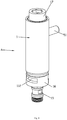
Fig. 1 illustrates a perspective view of a waterway slide switch device ofEmbodiment 1. -
Fig. 2 illustrates an exploded perspective view of the waterway slide switch device ofEmbodiment 1. -
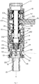
FIG. 3 illustrates a first cross-sectional view of the waterway slide switch device ofEmbodiment 1 when water flows downward. -
FIG. 4 illustrates a second cross-sectional view of the waterway slide switch device ofEmbodiment 1 when water flows upward. -
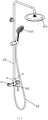
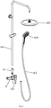
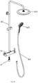
FIG. 5 illustrates a perspective view of a water outletdevice using Embodiment 1. -
FIG. 6 illustrates an exploded perspective view of the water outletdevice using Embodiment 1. -
FIG. 7 illustrates a cross-sectional view of the water outletdevice using Embodiment 1. -
FIG. 8 illustrates a perspective view of a waterway slide switch device ofEmbodiment 2. -
FIG. 9 illustrates an exploded perspective view of the waterway slide switch device ofEmbodiment 2. -
FIG. 10 illustrates a first cross-sectional view of the waterway slide switch device ofEmbodiment 2 when water flows downward -
FIG. 11 illustrates the second cross-sectional view of the waterway slide switch device ofEmbodiment 2 when water flows upward. -
FIG. 12 illustrates a perspective view of a water outletdevice using Embodiment 2. -
FIG. 13 illustrates an exploded perspective view of the water outletdevice using Embodiment 2. -
FIG. 14 illustrates a cross-sectional view of the water outletdevice using Embodiment 2. - Reference numbers: waterway slide switch device A,
valve body member 1, slidingmember 2,pressure component 3, resetelastic body 4, operatingmember 5,water inlet passage 11,water dividing cavity 111,water inlet 112, firstwater dividing passage 12, second water dividing passage 12', limitingmechanism 13, limitinggroove 131,installation cavity 14,gap section 141,water outlet section 142, sealingmember 143, first joint 15,first step 151,first housing 16, second throughhole 161, second joint 17,shaft sleeve 18, first throughhole 181,outer flange 182, sealingsleeve 19; slidingsleeve 21, sleeveinner portion 211,water hole 212, correspondingslot 213, sealingportion 22; protrudingportion 31, limitingmember 32;dial rod 51, lockingmember 52,insertion portion 521;faucet body 6,control mechanism 61, handle 611,hard pipe 62,top shower 621,hose 63, and hand-heldshower 631.
waterway slide switch device A', second housing 16',second step 162,outer sleeve 53,inner sleeve 54,insert member 541, and handle 611'. - Referring to
Figs. 1-4 , a dotted line with arrow in drawings indicates a direction of water flow. A waterway slide switch device comprises avalve body member 1, a slidingmember 2, apressure component 3, a resetelastic body 4 and an operatingmember 5. Thevalve body member 1 is disposed with awater inlet passage 11 and twowater dividing passages 12 and 12', and the slidingmember 2 is slidably connected to an inner side of thevalve body member 1 to enable the twowater dividing passages 12 and 12' to be switched to be in communication with thewater inlet passage 11 due to the sliding. Thepressure component 3 is disposed in thevalve body member 1, thepressure component 3 isolates the twowater dividing passages 12 and 12' and cooperates with the twowater dividing passages 12 and 12', so that water flow in the twowater dividing passages 12 and 12' is configured to act on thepressure component 3 to enable thepressure component 3 be subjected to water force. The slidingmember 2 and thepressure component 3 are configured to slide relatively, and thevalve body member 1 is disposed with a limitingmechanism 13 configured to limit a movement or a movement distance of thepressure component 3. The limitingmechanism 13 is configured to limit thepressure component 3 to move or to limit thepressure component 3 to only slide within a smaller sliding distance. The smaller sliding distance is relative to a sliding distance of the slidingmember 2, for example, a ratio of the two is 1: (5-10). The resetelastic body 4 is disposed between the slidingmember 2 or the operatingmember 5 and thevalve body member 1. When a front waterway is off, the resetelastic body 4 enables the waterway slide switch device A to be automatically reset to an initial state. The operatingmember 5 is operatively connected to the slidingmember 2 to drive the slidingmember 2 to slide, for example, the drawings illustrates an upward and downward sliding. - An
installation cavity 14 is disposed in thevalve body member 1. The slidingmember 2 comprises a slidingsleeve 21 and a sealingportion 22 secured to an outer side of the slidingsleeve 21, and the sealingportion 22 is, for example, a sealing ring. The slidingsleeve 21 is slidably connected to an inner side of theinstallation cavity 14, for example, the drawings illustrates an upward and downward sliding. The slidingsleeve 21 drives the sealingportion 22 to slide to the twowater dividing passages 12 and 12' to be switched to be in communication with thewater inlet passage 11. The slidingsleeve 21 is hermetically and slidably connected to an outer side of thepressure component 3. The twowater dividing passages 12 and 12' are respectively a firstwater dividing passage 12 and a second water dividing passage 12'. The firstwater dividing passage 12 comprises a sleeveinner portion 211 disposed in the slidingsleeve 21 and water flowing in the sleeveinner portion 211 is configured to act on a first end surface of thepressure component 3 to generate the water force, for example, referring to the drawings, the water flowing in the sleeveinner portion 211 is configured to act on an upper end surface of thepressure component 3. The second water dividing passage 12' comprises agap section 141 disposed between the slidingsleeve 21 and thevalve body member 1 and awater outlet section 142 in communication with thegap section 141, referring to the drawings, thegap section 141 is defined between an inner wall of theinstallation cavity 14 and a shaft sleeve component. An area of theinstallation cavity 14 disposed below thepressure component 3 defines thewater outlet section 142. Water flowing in thewater outlet section 142 is configured to act on a lower end surface (i.e., a second end surface) of thepressure component 3 to generate water force. The first end surface and the second end surface of thepressure component 3 are opposite. Thewater outlet section 142 and the sleeveinner portion 211 are respectively disposed on two sides of thepressure component 3. The slidingsleeve 21 comprises awater hole 212 penetrating an inner side and an outer side of the sleeveinner portion 211 of the sliding sleeve. A sealingmember 143 is disposed between the inner wall of theinstallation cavity 14 and the slidingsleeve 21. The sealing member, the water hole and the pressure component are disposed at intervals along a length of the sliding sleeve. Moreover, as thepressure component 3 does not slide or a sliding distance of thepressure component 3 is short, thepressure component 3 will not block thewater hole 212. - Inlets of the two
water dividing passages 12 and 12' are separated and face each other. Thewater inlet passage 11 comprises awater dividing cavity 111 disposed in thevalve body member 1 and disposed between the inlets of the twowater dividing passages 12 and 12'. An area of theinstallation cavity 14 disposed between the inlets of the twowater dividing passages 12 and 12' defines the water dividing cavity. The slidingsleeve 21 passes through thewater dividing cavity 111 and the sealingportion 22 is disposed in thewater dividing cavity 111. The sealing portion is configured to alternatively seal the inlets of the two water dividing passages to achieve switching. Thevalve body member 1 comprises awater inlet 112 penetrating an inner side and an outer side of theinstallation cavity 14, thewater inlet 112 is in communication with thewater dividing cavity 111, and the water inlet passage comprises the water inlet and the water dividing cavity. - The
pressure component 3 comprises a mating portion hermetically and slidably connected to an inner side of the slidingsleeve 21 and a protrudingportion 31 secured to the mating portion. The protrudingportion 31 comprises a protruding rod, and the protruding rod protrudes out of the slidingsleeve 21 and is disposed in thewater outlet section 142. The protrudingportion 31 further comprises a limitingmember 32, the limitingmember 32 is, for example, a circular ring, the circular ring surrounds the protruding rod and is secured to an end of the protruding rod by spokes, a passage configured to enable water to flow through is defined between adjacent spokes. The limitingmechanism 13 comprises a limitinggroove 131 extending inward from an inner wall of thewater outlet section 142, and the circular ring is disposed in the limitinggroove 131, and the limiting groove cooperates with the limiting member to achieve limiting. - The
valve body member 1 comprises the shaft sleeve component, a first joint 15, afirst housing 16 and a second joint 17. The shaft sleeve component comprises ashaft sleeve 18 and a sealingsleeve 19. Theshaft sleeve 18 and the sealingsleeve 19 are secured in thefirst housing 16 and cooperate to define theinstallation cavity 14. The shaft sleeve is separated from the sealing sleeve up and down, ports of the shaft sleeve and the sealing sleeve facing each other define the inlets of the two water dividing passages, and the separated area defines thewater dividing cavity 111. The first joint 15 is secured in a lower port of thefirst housing 16 to enable the first joint 15 to be relatively secured to and be in communication with a lower end of the sealingsleeve 19. The second joint 17 is secured to an upper port of thefirst housing 16 to enable the second joint 17 to be relatively secured to and be in communication with an upper end of theshaft sleeve 18. Thefirst housing 16 comprises thewater inlet 112 penetrating the inner side and the outer side and configured to guide the water to flow into thewater dividing cavity 111. The first joint 15 is disposed with afirst step 151 facing the sealingsleeve 19. A first end surface of the sealingsleeve 19 is separated from and faces the first step of the first joint to define the limiting groove. - The
shaft sleeve 18 comprises a first throughhole 181 penetrating an inner side and an outer side, and thefirst housing 16 comprises a second throughhole 161 penetrating an inner side and an outer side. The operatingmember 5 is disposed in the first throughhole 181 and the second throughhole 161 and is secured to the slidingsleeve 21 to drive the sliding member to slide. The sealingmember 143 is disposed between the first throughhole 181 and thewater hole 212 to prevent water from thewater hole 212 from flowing into the first throughhole 181. Further, the operatingmember 5 comprises adial rod 51 and a lockingmember 52. Thedial rod 51 is secured to the slidingsleeve 21 through the lockingmember 52. The lockingmember 52 comprises an arc-shaped sleeve. An opening of an inner wall of the arc-shaped sleeve protrude to define aninsertion portions 521, the slidingsleeve 21 is disposed with acorresponding slot 213, the insertion portions are disposed in the corresponding slot, and thedial rod 51 is locked to the arc-shaped sleeve. The resetelastic body 4 is, for example, a spring, the spring surrounds the slidingsleeve 21 and abuts the lockingmember 52 and anouter flange 182 protruding from an outer side of theshaft sleeve 18. In this embodiment, the reset elastic body is disposed between the operating member and thevalve body member 1, and as required, can also be directly disposed between the sliding member and the valve body member. - Referring to
Figs. 5 to 7 , a dotted line with arrow indicates a direction of water flow. A water outlet device comprises afaucet body 6, acontrol mechanism 61 and the waterway slide switch device A. Thefaucet body 6 is disposed with the front waterway. Thecontrol mechanism 61 cooperates with the front waterway to control waterway. The front waterway comprises a cold-water passage, a hot water passage and a mixed water passage. Thecontrol mechanism 61 is, for example, a control mechanism configured to adjust water temperature, flow rate and on-off action. The water temperature, the flow rate and the on-off action can be controlled by ahandle 611 of thecontrol mechanism 61. The control mechanism is existing techniques. The control mechanism is disposed on a middle portion of thefaucet body 6, and the handle is disposed in front of the middle portion of thefaucet body 6. The waterway slide switch device A is disposed in thefaucet body 6, the front waterway is in communication with thewater inlet passage 11 of the waterway slide switch device A, and an upper portion of thevalve body member 1 extends out of an upper side of thefaucet body 6. The first water dividing passage of the waterway slide switch device A is connected to ahard pipe 62 of thefaucet body 6 through the second joint, an end of thehard pipe 62 is connected to atop shower 621. The second water dividing passage is connected to ahose 63 through the first joint. An end of thehose 63 is connected to a hand-heldshower 631. The operatingmember 5 is disposed above thefaucet body 6. An appearance of the water outlet device of this embodiment can be simplified to be consistent with an appearance of a lower support pipe, and the appearance is simple and beautiful. - In an initial water outlet state of the water outlet device, referring to
Fig. 3 , when the control mechanism is opened, water flows along a side of the waterway slide switch device, and the sealing portion of the slidingsleeve 21 blocks a water dividing hole of an upper water dividing passage (an upper water outlet sealing surface) of the shaft sleeve due to the slidingsleeve 21 being subjected to an elastic force of the reset elastic body. At this time, a water outlet of the top shower is closed. The water flows through an inner cavity of the sealing sleeve and flows out of the hand-held shower. The water is closed and a reset: when the water flows out of the top shower, the control mechanism of the faucet body is closed, and water stops to flow out of the faucet. Water pressure applied to the sealing portion of the slidingsleeve 21 disappears, the slidingsleeve 21 moves upward due to the elastic force of the reset elastic body to block the water dividing hole of the upper water dividing passage of the shaft sleeve, a water dividing hole of a lower water dividing passage of the sealing sleeve is open, and a default state that the water flows of the hand-held shower is reset. When the water flows out of the hand-held shower, when the water is off, the slidingsleeve 21 is maintained in this position due to the elastic force of the reset elastic body and is maintained in the initial state. During a switching process, the dial rod slides, the dial rod drives the slidingsleeve 21 to slide, and the sealing portion is switched to block the upper water dividing passage and lower water dividing passage. Further, in the switching process, an operating force should overcome a water pressure applied to the slidingsleeve 21 and the sealing portion. As a middle portion of the slidingsleeve 21 comprises a through hole, the through hole is disposed with the pressure component, the water pressure applied to the pressure component is limited by the limiting mechanism of the valve body member, and the sliding sleeve is configured to slide relative to the pressure component. Therefore, the water pressure applied to the pressure component is not applied on the slidingsleeve 21, an area of the slidingsleeve 21 subjected to the water pressure is greatly reduced. At this time, the water pressure is smaller, and the switching is achieved in a labor-saving way. - Referring to
Figs. 8-11 , a dotted line with arrow in drawings indicates a direction of water flow. This embodiment differs fromEmbodiment 1 in that: thevalve body member 1 of the waterway slide switch device A' comprises a second housing 16' and ashaft sleeve 18 hermetically secured in the second housing 16'. A lower section of the second housing 16' is hermetically secured to an upper section of theshaft sleeve 18, and theshaft sleeve 18 cooperates with the second housing 16' and is disposed with theinstallation cavity 14. The second joint 17 is secured in the second housing 16' and the second joint is in communication with the second housing. The second housing 16' is disposed with asecond step 162 facing the second joint. A lower end surface of the second joint is separated from the second step of the second housing to define a limiting groove. The firstwater dividing passage 12 comprises the sleeveinner portion 211 disposed in the slidingsleeve 21, and the water flow in the sleeveinner portion 211 is configured to act on the first end surface of thepressure component 3 to generate the water force, referring to the drawings, the water flowing in the sleeveinner portion 211 is configured to act on a lower end surface of thepressure component 3. The second water dividing passage 12' comprises agap section 141 disposed between the slidingsleeve 21 and the second housing and awater outlet section 142 in communication with thegap section 141. Referring to the drawings, thegap section 141 is defined between an inner wall of the second housing 16' and the shaft sleeve component. An area of theinstallation cavity 14 disposed above thepressure component 3 defines thewater outlet section 142, and the water flowing in thewater outlet section 142 is configured to act on an upper end surface of thepressure component 3 to generate the water force. - The operating
member 5 comprises anouter sleeve 53 and aninner sleeve 54 secured in the outer sleeve. The inner sleeve surrounds an outer side of the shaft sleeve. Theinner sleeve 54 protrudes to define aninsert member 541, and theinsert member 541 passes through the first through hole and is locked to the slidingsleeve 21. Theelastic body 5 surrounds the sliding sleeve, and theelastic body 4 is disposed between and abuts the operatingmember 5 and the first joint. - Referring to
Figs. 12-14 , a dotted line with arrow in the drawings indicates the direction of the water flow. A water outlet device comprises afaucet body 6, acontrol mechanism 61 and a waterway slide switch device A'. Thefaucet body 6 is disposed with the front waterway, and the control mechanism cooperates with the front waterway to control waterway. The control mechanism is disposed on a middle portion of thefaucet body 6, and a handle 611' of the control mechanism is disposed at a side end of thefaucet body 6. The waterway slide switch device A' is disposed in thefaucet body 6, and the front waterway is in communication with thewater inlet passage 11 of the waterway slide switch device. The first water dividing passage of the waterway slide switch device is in communication with ahose 63 through a lower port of a valve shaft, an end of thehose 63 is connected to a hand-heldshower 631. The second water dividing passage is secured to ahard pipe 62 of thefaucet body 6 by the second joint, and an end of thehard pipe 62 is connected to atop shower 621. The operatingmember 5 is disposed below thefaucet body 6. An appearance of the water outlet device of this embodiment is simplified to be consist with a lower support pipe, and the appearance is simple and beautiful. - The invention may be summarized as follows: The present disclosure discloses a waterway slide switch device and a water outlet device. The waterway slide switch device comprises a valve body member and a sliding member, the valve body member is disposed with a water inlet passage and two water dividing passages, the sliding member is configured to slide relative to the valve body member to enable the two water dividing passages to be switched to be in communication with the water inlet passage due to the sliding; further comprises a pressure component, the pressure component is disposed in the valve body member and cooperates with the two water dividing passages to enable water flowing in the two water dividing passages to be both configured to act on the pressure component to enable the pressure component to be subjected to water force, the sliding member and the pressure component are configured to slide relative to each other, and the valve body member is disposed with a limiting mechanism configured to limit a movement or a movement distance of the pressure component. It has following advantages: the water force applied to the sliding member is reduced and a labor-saving switching is achieved.
- The invention may also be summarized as follows:
- 1. A waterway slide switch device comprises a valve body member and a sliding member, the valve body member is disposed with a water inlet passage and two water dividing passages, the sliding member is configured to slide relative to the valve body member to enable the two water dividing passages to be switched to be in communication with the water inlet passage due to the sliding; characterized in that: which further comprises a pressure component, the pressure component is disposed in the valve body member and cooperates with the two water dividing passages to enable water flowing in the two water dividing passages to be both configured to act on the pressure component to enable the pressure component to be subjected to water force, the sliding member and the pressure component are configured to slide relative to each other, and the valve body member is disposed with a limiting mechanism configured to limit a movement or a movement distance of the pressure component.
- 2. The waterway slide switch device according to
item 1, characterized in that: the pressure component isolates the two water dividing passages. - 3. The waterway slide switch device according to
item 1, characterized in that: a reset elastic body is disposed between the sliding member and the valve body member. - 4. The waterway slide switch device according to
item 1, characterized in that: the sliding member comprises a sliding sleeve and a sealing portion secured to an outer side of the sliding sleeve, the sliding sleeve drives the sealing portion to slide to enable the two water dividing passages to be switched to be in communication with the water inlet passage, the sliding sleeve is hermetically and slidably connected to an outer side of the pressure component; the two water dividing passages are a first water dividing passage and a second water dividing passage, the first water dividing passage comprises a sleeve inner portion disposed in the sliding sleeve, water flowing in the sleeve inner portion is configured to act on a first end surface of the pressure component to generate the water force, the second water dividing passage comprises a gap section disposed between the sliding sleeve and the valve body member and a water outlet section in communication with the gap section, water flowing in the water outlet section is configured to act on a second end surface of the pressure component to generate the water force. - 5. The waterway slide switch device according to
item 4, characterized in that: the sliding sleeve comprises a water hole penetrating an inner side and an outer side of the sleeve inner portion of the sliding sleeve, and the water outlet section and the sleeve inner portion are respectively disposed on two sides of the pressure component. - 6. The waterway slide switch device according to
item 5, characterized in that: an installation cavity is disposed in the valve body member, the sliding sleeve is slidably connected to an inner side of the installation cavity, a sealing member is disposed between an inner wall of the installation cavity and the sliding sleeve, and the sealing member, the water hole and the pressure component are disposed at intervals along a length of the sliding sleeve. - 7. The waterway slide switch device according to
item 6, characterized in that: the water outlet section is defined in the installation cavity, and the gap section is defined between the inner wall of the installation cavity and a shaft sleeve component. - 8. The waterway slide switch device according to
item 4, characterized in that: the pressure component comprises a protruding portion protruding out of the sliding sleeve and disposed in the water outlet section, the limiting mechanism is disposed on the water outlet section, and the protruding portion cooperates with the limiting mechanism to achieve limiting. - 9. The waterway slide switch device according to item 8, characterized in that: the protruding portion is disposed with a limiting member, the limiting mechanism comprises a limiting groove extending inward from an inner wall of the water outlet section, the limiting member is disposed in the limiting groove, and the limiting groove cooperates with the limiting member to achieve the limiting.
- 10. The waterway slide switch device according to
item 4, characterized in that: inlets of the two water dividing passages are separated and face each other, the water inlet passage comprises a water dividing cavity disposed in the valve body member and disposed between the inlets of the two water dividing passages, the sliding sleeve passes through the water dividing cavity, the sealing portion is disposed in the water dividing cavity, and the inlets of the two water dividing passages is alternatively closed to achieve switching due to the sealing portion. - 11. The waterway slide switch device according to item 10, characterized in that: an installation cavity is disposed in the valve body member, the sliding sleeve is slidably connected to an inner side of the installation cavity, the water outlet section is defined in the installation cavity, the gap section is defined between the inner wall of the installation cavity and a shaft sleeve component; the valve body member comprises a water inlet penetrating an inner side and an outer side, and the water inlet is in communication with the water dividing cavity.
- 12. The waterway slide switch device according to
item 7 or 11, characterized in that: the valve body member comprises the shaft sleeve component and a first joint hermetically secured to a first end of the shaft sleeve component, the installation cavity is disposed in the shaft sleeve component, the first joint is in communication with a first port of the shaft sleeve component, the first joint is disposed with a step facing the shaft sleeve component; the protruding portion comprises a limiting member, the pressure component comprises a protruding portion protruding out of the sliding sleeve, the limiting mechanism comprises a limiting groove defined due to a first end surface of the shaft sleeve component being separated from the step of the first joint, the limiting member is disposed in the limiting groove, and the limiting groove cooperates with the limiting member to achieve limiting. - 13. The waterway slide switch device according to
item 12, characterized in that: the valve body member comprises a housing and a second joint, the shaft sleeve portion is secured in the housing, the second joint is secured to a second end of the shaft sleeve component, and the second joint is in communication with a second port of the shaft sleeve component. - 14. The waterway slide switch device according to
item 13, characterized in that: the shaft sleeve component comprises a shaft sleeve and a sealing sleeve, the shaft sleeve and the sealing sleeve are secured in the housing, the shaft sleeve is separated from the sealing sleeve, ports of the shaft sleeve and the sealing sleeve facing to each other define the inlets of the two water dividing passages. - 15. The waterway slide switch device according to
item 12, characterized in that: which comprises an operating member configured to move relative to the valve body member, the valve body member comprises a housing, the shaft sleeve component is secured in the housing, the shaft sleeve component comprises a first through hole penetrating an inner side and an outer side, the housing comprises a second through hole penetrating an inner side and an outer side, the operating member is disposed in the first through hole and the second through hole and is operatively connected to the sliding member to drive the sliding member to slide. - 16. The waterway slide switch device according to
item 4, characterized in that: the valve body member comprises a housing and a shaft sleeve hermetically secured in the housing, the shaft sleeve cooperates with the housing and is disposed with an installation cavity, the sliding sleeve is slidably connected to an inner side of the installation cavity, a sealing member is disposed between an inner wall of the installation cavity and the sliding sleeve, and the sealing member, the water hole and the pressure component are disposed at intervals along a length of the sliding sleeve. - 17. The waterway slide switch device according to
item 16, characterized in that: the valve body member further comprises a second joint, the second joint is secured in the housing, the second joint is in communication with the housing, the housing is disposed with a step facing the second joint; the protruding portion comprises a limiting member, the pressure component comprises a protruding portion protruding out of the sliding sleeve, the limiting mechanism comprises a limiting groove defined due to an inner end surface of the second joint being separated from the step of the housing, the limiting member is disposed in the limiting groove, and the limiting groove cooperates with the limiting member to achieve limiting. - 18. The waterway slide switch device according to
item 1, characterized in that: which further comprises an operating member configured to move relative to the valve body member, the valve body member comprises a giving hole penetrating an inner side and an outer side, and the operating member is disposed in the giving hole and is operatively connected to the sliding member to drive the sliding member to slide. - 19. A waterway slide switch device comprises a valve body member and a sliding member, the valve body member is disposed with a water inlet passage and two water dividing passages, the sliding member is configured to slide relative to the valve body member to enable the two water dividing passages to be switched to be in communication with the water inlet passage due to the sliding; characterized in that: which further comprises a pressure component, the pressure component is disposed in the valve body member and isolates the two water dividing passages, the sliding member and the pressure component are configured to slide relative to each other, and the valve body member is disposed with a limiting mechanism configured to limit a movement or a movement distance of the pressure component.
- 20. A water outlet device comprises a faucet body and a control mechanism, characterized in that, which further comprises the waterway slide switch device according to
items - The aforementioned embodiments are merely some embodiments of the present disclosure, and the scope of the disclosure is not limited thereto. Thus, it is intended that the present disclosure cover any modifications and variations of the presently presented embodiments provided they are made without departing from the appended claims and the specification of the present disclosure by those skilled in the art.
Claims (16)
- A waterway slide switch device comprises a valve body member and a sliding member, the valve body member is disposed with a water inlet passage and two water dividing passages, the sliding member is configured to slide relative to the valve body member to enable the two water dividing passages to be switched to be in communication with the water inlet passage due to the sliding; characterized in that: which further comprises a pressure component, the pressure component is disposed in the valve body member and cooperates with the two water dividing passages to enable water flowing in the two water dividing passages to be both configured to act on the pressure component to enable the pressure component to be subjected to water force, the sliding member and the pressure component are configured to slide relative to each other, and the valve body member is disposed with a limiting mechanism configured to limit a movement or a movement distance of the pressure component.
- The waterway slide switch device according to claim 1, characterized in that: the pressure component isolates the two water dividing passages.
- The waterway slide switch device according to claim 1 and/or 2, characterized in that: a reset elastic body is disposed between the sliding member and the valve body member.
- The waterway slide switch device according to any one or more of claims 1 to 3, characterized in that: the sliding member comprises a sliding sleeve and a sealing portion secured to an outer side of the sliding sleeve, the sliding sleeve drives the sealing portion to slide to enable the two water dividing passages to be switched to be in communication with the water inlet passage, the sliding sleeve is hermetically and slidably connected to an outer side of the pressure component; the two water dividing passages are a first water dividing passage and a second water dividing passage, the first water dividing passage comprises a sleeve inner portion disposed in the sliding sleeve, water flowing in the sleeve inner portion is configured to act on a first end surface of the pressure component to generate the water force, the second water dividing passage comprises a gap section disposed between the sliding sleeve and the valve body member and a water outlet section in communication with the gap section, water flowing in the water outlet section is configured to act on a second end surface of the pressure component to generate the water force.
- The waterway slide switch device according to claim 4, characterized in that: the sliding sleeve comprises a water hole penetrating an inner side and an outer side of the sleeve inner portion of the sliding sleeve, and the water outlet section and the sleeve inner portion are respectively disposed on two sides of the pressure component.
- The waterway slide switch device according to claim 5, characterized in that: an installation cavity is disposed in the valve body member, the sliding sleeve is slidably connected to an inner side of the installation cavity, a sealing member is disposed between an inner wall of the installation cavity and the sliding sleeve, and the sealing member, the water hole and the pressure component are disposed at intervals along a length of the sliding sleeve.
- The waterway slide switch device according to claim 6, characterized in that: the water outlet section is defined in the installation cavity, and the gap section is defined between the inner wall of the installation cavity and a shaft sleeve component.
- The waterway slide switch device according to any one or more of claims 4 to 7, characterized in that: the pressure component comprises a protruding portion protruding out of the sliding sleeve and disposed in the water outlet section, the limiting mechanism is disposed on the water outlet section, and the protruding portion cooperates with the limiting mechanism to achieve limiting.
- The waterway slide switch device according to claim 8, characterized in that: the protruding portion is disposed with a limiting member, the limiting mechanism comprises a limiting groove extending inward from an inner wall of the water outlet section, the limiting member is disposed in the limiting groove, and the limiting groove cooperates with the limiting member to achieve the limiting.
- The waterway slide switch device according to any one or more of claims 4 to 9, characterized in that: inlets of the two water dividing passages are separated and face each other, the water inlet passage comprises a water dividing cavity disposed in the valve body member and disposed between the inlets of the two water dividing passages, the sliding sleeve passes through the water dividing cavity, the sealing portion is disposed in the water dividing cavity, and the inlets of the two water dividing passages is alternatively closed to achieve switching due to the sealing portion.
- The waterway slide switch device according to claim 10, characterized in that: an installation cavity is disposed in the valve body member, the sliding sleeve is slidably connected to an inner side of the installation cavity, the water outlet section is defined in the installation cavity, the gap section is defined between the inner wall of the installation cavity and a shaft sleeve component; the valve body member comprises a water inlet penetrating an inner side and an outer side, and the water inlet is in communication with the water dividing cavity.
- The waterway slide switch device according to any one or more of claims 7 to 11, characterized in that: the valve body member comprises the shaft sleeve component and a first joint hermetically secured to a first end of the shaft sleeve component, the installation cavity is disposed in the shaft sleeve component, the first joint is in communication with a first port of the shaft sleeve component, the first joint is disposed with a step facing the shaft sleeve component; the protruding portion comprises a limiting member, the pressure component comprises a protruding portion protruding out of the sliding sleeve, the limiting mechanism comprises a limiting groove defined due to a first end surface of the shaft sleeve component being separated from the step of the first joint, the limiting member is disposed in the limiting groove, and the limiting groove cooperates with the limiting member to achieve limiting.
- The waterway slide switch device according to any one or more of claims 7 to 12, characterized in that: which comprises an operating member configured to move relative to the valve body member, the valve body member comprises a housing, the shaft sleeve component is secured in the housing, the shaft sleeve component comprises a first through hole penetrating an inner side and an outer side, the housing comprises a second through hole penetrating an inner side and an outer side, the operating member is disposed in the first through hole and the second through hole and is operatively connected to the sliding member to drive the sliding member to slide.
- The waterway slide switch device according to any one or more of claims 4 to 13, characterized in that: the valve body member comprises a housing and a shaft sleeve hermetically secured in the housing, the shaft sleeve cooperates with the housing and is disposed with an installation cavity, the sliding sleeve is slidably connected to an inner side of the installation cavity, a sealing member is disposed between an inner wall of the installation cavity and the sliding sleeve, and the sealing member, the water hole and the pressure component are disposed at intervals along a length of the sliding sleeve.
- A waterway slide switch device comprises a valve body member and a sliding member, the valve body member is disposed with a water inlet passage and two water dividing passages, the sliding member is configured to slide relative to the valve body member to enable the two water dividing passages to be switched to be in communication with the water inlet passage due to the sliding; characterized in that: which further comprises a pressure component, the pressure component is disposed in the valve body member and isolates the two water dividing passages, the sliding member and the pressure component are configured to slide relative to each other, and the valve body member is disposed with a limiting mechanism configured to limit a movement or a movement distance of the pressure component.
- A water outlet device comprises a faucet body and a control mechanism, characterized in that, which further comprises the waterway slide switch device according to any one or more of claims 1 to 15, the faucet body is disposed with a front waterway, the control mechanism cooperates with the front waterway to control waterway, and the front waterway is in communication with the water inlet passage of the waterway slide switch device.
Applications Claiming Priority (1)
| Application Number | Priority Date | Filing Date | Title |
|---|---|---|---|
| CN202010279488.1A CN113513609B (en) | 2020-04-10 | 2020-04-10 | Waterway sliding switching device and water outlet device |
Publications (2)
| Publication Number | Publication Date |
|---|---|
| EP3896318A1 true EP3896318A1 (en) | 2021-10-20 |
| EP3896318B1 EP3896318B1 (en) | 2023-12-13 |
Family
ID=75497789
Family Applications (1)
| Application Number | Title | Priority Date | Filing Date |
|---|---|---|---|
| EP21167931.1A Active EP3896318B1 (en) | 2020-04-10 | 2021-04-12 | Waterway slide switch device and water outlet device |
Country Status (2)
| Country | Link |
|---|---|
| EP (1) | EP3896318B1 (en) |
| CN (1) | CN113513609B (en) |
Cited By (3)
| Publication number | Priority date | Publication date | Assignee | Title |
|---|---|---|---|---|
| CN114060567A (en) * | 2021-11-03 | 2022-02-18 | 厦门建霖健康家居股份有限公司 | Switching water nozzle and pull tap |
| CN114377867A (en) * | 2021-12-30 | 2022-04-22 | 开平市汉顺洁具实业有限公司 | Water route switching structure of water outlet terminal |
| US20230311135A1 (en) * | 2022-04-02 | 2023-10-05 | Xiamen Rainshower Co. Ltd. | Multifunctional handheld shower |
Citations (6)
| Publication number | Priority date | Publication date | Assignee | Title |
|---|---|---|---|---|
| US2939474A (en) * | 1957-10-11 | 1960-06-07 | Simone Benjamin J De | Portable diverter valve |
| US5163465A (en) * | 1991-09-20 | 1992-11-17 | King Lloyd H Sr | Vacuum breaker venting valve |
| DE4141172A1 (en) * | 1991-12-13 | 1993-06-17 | Hansa Metallwerke Ag | Change over element for bath-shower tap fitting - has drawback handle with operating head, held by spring, adjoining end face of two part pressure member |
| WO2001090615A1 (en) * | 2000-05-25 | 2001-11-29 | Ramon Soler Fornt | Water distribution valve for bath and shower faucets |
| US20180283566A1 (en) * | 2017-04-03 | 2018-10-04 | Don Ptashne | Flow diverter valve |
| CN110056682A (en) | 2019-03-18 | 2019-07-26 | 厦门建霖健康家居股份有限公司 | A kind of waterway switching device and shower |
Family Cites Families (2)
| Publication number | Priority date | Publication date | Assignee | Title |
|---|---|---|---|---|
| CN206582359U (en) * | 2017-01-24 | 2017-10-24 | 厦门松霖科技股份有限公司 | Through type switching valve |
| CN212643631U (en) * | 2020-04-10 | 2021-03-02 | 厦门松霖科技股份有限公司 | Waterway sliding switching device and water outlet device |
-
2020
- 2020-04-10 CN CN202010279488.1A patent/CN113513609B/en active Active
-
2021
- 2021-04-12 EP EP21167931.1A patent/EP3896318B1/en active Active
Patent Citations (6)
| Publication number | Priority date | Publication date | Assignee | Title |
|---|---|---|---|---|
| US2939474A (en) * | 1957-10-11 | 1960-06-07 | Simone Benjamin J De | Portable diverter valve |
| US5163465A (en) * | 1991-09-20 | 1992-11-17 | King Lloyd H Sr | Vacuum breaker venting valve |
| DE4141172A1 (en) * | 1991-12-13 | 1993-06-17 | Hansa Metallwerke Ag | Change over element for bath-shower tap fitting - has drawback handle with operating head, held by spring, adjoining end face of two part pressure member |
| WO2001090615A1 (en) * | 2000-05-25 | 2001-11-29 | Ramon Soler Fornt | Water distribution valve for bath and shower faucets |
| US20180283566A1 (en) * | 2017-04-03 | 2018-10-04 | Don Ptashne | Flow diverter valve |
| CN110056682A (en) | 2019-03-18 | 2019-07-26 | 厦门建霖健康家居股份有限公司 | A kind of waterway switching device and shower |
Cited By (4)
| Publication number | Priority date | Publication date | Assignee | Title |
|---|---|---|---|---|
| CN114060567A (en) * | 2021-11-03 | 2022-02-18 | 厦门建霖健康家居股份有限公司 | Switching water nozzle and pull tap |
| CN114377867A (en) * | 2021-12-30 | 2022-04-22 | 开平市汉顺洁具实业有限公司 | Water route switching structure of water outlet terminal |
| US20230311135A1 (en) * | 2022-04-02 | 2023-10-05 | Xiamen Rainshower Co. Ltd. | Multifunctional handheld shower |
| US12403487B2 (en) * | 2022-04-02 | 2025-09-02 | Xiamen Rainshower Co. Ltd. | Multifunctional handheld shower |
Also Published As
| Publication number | Publication date |
|---|---|
| EP3896318B1 (en) | 2023-12-13 |
| CN113513609B (en) | 2025-01-07 |
| CN113513609A (en) | 2021-10-19 |
Similar Documents
| Publication | Publication Date | Title |
|---|---|---|
| EP3896318B1 (en) | Waterway slide switch device and water outlet device | |
| CN110547711B (en) | Socket device with waterway switching function | |
| CN211117762U (en) | Go out water structure and tap | |
| US10239065B2 (en) | Flow control component and shower | |
| CN109915629B (en) | Socket device | |
| CN103511661B (en) | A kind of shower system combining pilot valve structure and apply this structure | |
| CN104747760B (en) | Control valve and the gondola water faucet including the control valve | |
| US10675643B2 (en) | Water discharge structure having reset function and a pull-out head having a water discharge structure | |
| US20130291975A1 (en) | Changeover valve | |
| CN215568341U (en) | Switch valve core, switching valve and shower device | |
| CN113769907B (en) | A water channel switching structure and water outlet device | |
| CN108458135B (en) | Pull-out faucet waterway switching control mechanism | |
| CN106795977A (en) | Stop valve | |
| CN110159804B (en) | Pipeline valves for closing and/or switching | |
| CN214743519U (en) | Switch temperature-regulating water-dividing valve core | |
| CN212643631U (en) | Waterway sliding switching device and water outlet device | |
| CN218718981U (en) | Water outlet device | |
| CN117138992B (en) | Water outlet device | |
| GB2595764A (en) | Thermostatic valve with push for opening/closing and rotation for temperature regulation and faucet device | |
| US20230128541A1 (en) | Water diversion valve and shower device | |
| CN108940623B (en) | Advanced healthy shower device | |
| CN215483372U (en) | Valve and sanitary equipment thereof | |
| CN108150679B (en) | An integrated spool and shower valve | |
| CN112576783B (en) | Switching stop valve for faucet and faucet | |
| CN214864474U (en) | A water outlet device and shower |
Legal Events
| Date | Code | Title | Description |
|---|---|---|---|
| PUAI | Public reference made under article 153(3) epc to a published international application that has entered the european phase |
Free format text: ORIGINAL CODE: 0009012 |
|
| STAA | Information on the status of an ep patent application or granted ep patent |
Free format text: STATUS: REQUEST FOR EXAMINATION WAS MADE |
|
| 17P | Request for examination filed |
Effective date: 20210419 |
|
| AK | Designated contracting states |
Kind code of ref document: A1 Designated state(s): AL AT BE BG CH CY CZ DE DK EE ES FI FR GB GR HR HU IE IS IT LI LT LU LV MC MK MT NL NO PL PT RO RS SE SI SK SM TR |
|
| B565 | Issuance of search results under rule 164(2) epc |
Effective date: 20210916 |
|
| RBV | Designated contracting states (corrected) |
Designated state(s): AL AT BE BG CH CY CZ DE DK EE ES FI FR GB GR HR HU IE IS IT LI LT LU LV MC MK MT NL NO PL PT RO RS SE SI SK SM TR |
|
| GRAP | Despatch of communication of intention to grant a patent |
Free format text: ORIGINAL CODE: EPIDOSNIGR1 |
|
| STAA | Information on the status of an ep patent application or granted ep patent |
Free format text: STATUS: GRANT OF PATENT IS INTENDED |
|
| RIC1 | Information provided on ipc code assigned before grant |
Ipc: E03C 1/02 20060101ALI20230525BHEP Ipc: E03C 1/04 20060101ALI20230525BHEP Ipc: F16K 11/044 20060101AFI20230525BHEP |
|
| INTG | Intention to grant announced |
Effective date: 20230621 |
|
| GRAS | Grant fee paid |
Free format text: ORIGINAL CODE: EPIDOSNIGR3 |
|
| GRAA | (expected) grant |
Free format text: ORIGINAL CODE: 0009210 |
|
| STAA | Information on the status of an ep patent application or granted ep patent |
Free format text: STATUS: THE PATENT HAS BEEN GRANTED |
|
| AK | Designated contracting states |
Kind code of ref document: B1 Designated state(s): AL AT BE BG CH CY CZ DE DK EE ES FI FR GB GR HR HU IE IS IT LI LT LU LV MC MK MT NL NO PL PT RO RS SE SI SK SM TR |
|
| REG | Reference to a national code |
Ref country code: GB Ref legal event code: FG4D |
|
| REG | Reference to a national code |
Ref country code: CH Ref legal event code: EP |
|
| REG | Reference to a national code |
Ref country code: DE Ref legal event code: R096 Ref document number: 602021007585 Country of ref document: DE |
|
| REG | Reference to a national code |
Ref country code: IE Ref legal event code: FG4D |
|
| PG25 | Lapsed in a contracting state [announced via postgrant information from national office to epo] |
Ref country code: GR Free format text: LAPSE BECAUSE OF FAILURE TO SUBMIT A TRANSLATION OF THE DESCRIPTION OR TO PAY THE FEE WITHIN THE PRESCRIBED TIME-LIMIT Effective date: 20240314 |
|
| REG | Reference to a national code |
Ref country code: LT Ref legal event code: MG9D |
|
| PG25 | Lapsed in a contracting state [announced via postgrant information from national office to epo] |
Ref country code: LT Free format text: LAPSE BECAUSE OF FAILURE TO SUBMIT A TRANSLATION OF THE DESCRIPTION OR TO PAY THE FEE WITHIN THE PRESCRIBED TIME-LIMIT Effective date: 20231213 |
|
| REG | Reference to a national code |
Ref country code: NL Ref legal event code: MP Effective date: 20231213 |
|
| PG25 | Lapsed in a contracting state [announced via postgrant information from national office to epo] |
Ref country code: ES Free format text: LAPSE BECAUSE OF FAILURE TO SUBMIT A TRANSLATION OF THE DESCRIPTION OR TO PAY THE FEE WITHIN THE PRESCRIBED TIME-LIMIT Effective date: 20231213 |
|
| PG25 | Lapsed in a contracting state [announced via postgrant information from national office to epo] |
Ref country code: LT Free format text: LAPSE BECAUSE OF FAILURE TO SUBMIT A TRANSLATION OF THE DESCRIPTION OR TO PAY THE FEE WITHIN THE PRESCRIBED TIME-LIMIT Effective date: 20231213 Ref country code: GR Free format text: LAPSE BECAUSE OF FAILURE TO SUBMIT A TRANSLATION OF THE DESCRIPTION OR TO PAY THE FEE WITHIN THE PRESCRIBED TIME-LIMIT Effective date: 20240314 Ref country code: ES Free format text: LAPSE BECAUSE OF FAILURE TO SUBMIT A TRANSLATION OF THE DESCRIPTION OR TO PAY THE FEE WITHIN THE PRESCRIBED TIME-LIMIT Effective date: 20231213 Ref country code: BG Free format text: LAPSE BECAUSE OF FAILURE TO SUBMIT A TRANSLATION OF THE DESCRIPTION OR TO PAY THE FEE WITHIN THE PRESCRIBED TIME-LIMIT Effective date: 20240313 |
|
| REG | Reference to a national code |
Ref country code: AT Ref legal event code: MK05 Ref document number: 1640700 Country of ref document: AT Kind code of ref document: T Effective date: 20231213 |
|
| PG25 | Lapsed in a contracting state [announced via postgrant information from national office to epo] |
Ref country code: NL Free format text: LAPSE BECAUSE OF FAILURE TO SUBMIT A TRANSLATION OF THE DESCRIPTION OR TO PAY THE FEE WITHIN THE PRESCRIBED TIME-LIMIT Effective date: 20231213 |
|
| PG25 | Lapsed in a contracting state [announced via postgrant information from national office to epo] |
Ref country code: SE Free format text: LAPSE BECAUSE OF FAILURE TO SUBMIT A TRANSLATION OF THE DESCRIPTION OR TO PAY THE FEE WITHIN THE PRESCRIBED TIME-LIMIT Effective date: 20231213 Ref country code: RS Free format text: LAPSE BECAUSE OF FAILURE TO SUBMIT A TRANSLATION OF THE DESCRIPTION OR TO PAY THE FEE WITHIN THE PRESCRIBED TIME-LIMIT Effective date: 20231213 Ref country code: NO Free format text: LAPSE BECAUSE OF FAILURE TO SUBMIT A TRANSLATION OF THE DESCRIPTION OR TO PAY THE FEE WITHIN THE PRESCRIBED TIME-LIMIT Effective date: 20240313 Ref country code: NL Free format text: LAPSE BECAUSE OF FAILURE TO SUBMIT A TRANSLATION OF THE DESCRIPTION OR TO PAY THE FEE WITHIN THE PRESCRIBED TIME-LIMIT Effective date: 20231213 Ref country code: LV Free format text: LAPSE BECAUSE OF FAILURE TO SUBMIT A TRANSLATION OF THE DESCRIPTION OR TO PAY THE FEE WITHIN THE PRESCRIBED TIME-LIMIT Effective date: 20231213 Ref country code: HR Free format text: LAPSE BECAUSE OF FAILURE TO SUBMIT A TRANSLATION OF THE DESCRIPTION OR TO PAY THE FEE WITHIN THE PRESCRIBED TIME-LIMIT Effective date: 20231213 |
|
| PG25 | Lapsed in a contracting state [announced via postgrant information from national office to epo] |
Ref country code: IS Free format text: LAPSE BECAUSE OF FAILURE TO SUBMIT A TRANSLATION OF THE DESCRIPTION OR TO PAY THE FEE WITHIN THE PRESCRIBED TIME-LIMIT Effective date: 20240413 |
|
| PG25 | Lapsed in a contracting state [announced via postgrant information from national office to epo] |
Ref country code: CZ Free format text: LAPSE BECAUSE OF FAILURE TO SUBMIT A TRANSLATION OF THE DESCRIPTION OR TO PAY THE FEE WITHIN THE PRESCRIBED TIME-LIMIT Effective date: 20231213 Ref country code: AT Free format text: LAPSE BECAUSE OF FAILURE TO SUBMIT A TRANSLATION OF THE DESCRIPTION OR TO PAY THE FEE WITHIN THE PRESCRIBED TIME-LIMIT Effective date: 20231213 |
|
| PG25 | Lapsed in a contracting state [announced via postgrant information from national office to epo] |
Ref country code: SK Free format text: LAPSE BECAUSE OF FAILURE TO SUBMIT A TRANSLATION OF THE DESCRIPTION OR TO PAY THE FEE WITHIN THE PRESCRIBED TIME-LIMIT Effective date: 20231213 |
|
| PG25 | Lapsed in a contracting state [announced via postgrant information from national office to epo] |
Ref country code: SM Free format text: LAPSE BECAUSE OF FAILURE TO SUBMIT A TRANSLATION OF THE DESCRIPTION OR TO PAY THE FEE WITHIN THE PRESCRIBED TIME-LIMIT Effective date: 20231213 Ref country code: SK Free format text: LAPSE BECAUSE OF FAILURE TO SUBMIT A TRANSLATION OF THE DESCRIPTION OR TO PAY THE FEE WITHIN THE PRESCRIBED TIME-LIMIT Effective date: 20231213 Ref country code: RO Free format text: LAPSE BECAUSE OF FAILURE TO SUBMIT A TRANSLATION OF THE DESCRIPTION OR TO PAY THE FEE WITHIN THE PRESCRIBED TIME-LIMIT Effective date: 20231213 Ref country code: IT Free format text: LAPSE BECAUSE OF FAILURE TO SUBMIT A TRANSLATION OF THE DESCRIPTION OR TO PAY THE FEE WITHIN THE PRESCRIBED TIME-LIMIT Effective date: 20231213 Ref country code: IS Free format text: LAPSE BECAUSE OF FAILURE TO SUBMIT A TRANSLATION OF THE DESCRIPTION OR TO PAY THE FEE WITHIN THE PRESCRIBED TIME-LIMIT Effective date: 20240413 Ref country code: EE Free format text: LAPSE BECAUSE OF FAILURE TO SUBMIT A TRANSLATION OF THE DESCRIPTION OR TO PAY THE FEE WITHIN THE PRESCRIBED TIME-LIMIT Effective date: 20231213 Ref country code: CZ Free format text: LAPSE BECAUSE OF FAILURE TO SUBMIT A TRANSLATION OF THE DESCRIPTION OR TO PAY THE FEE WITHIN THE PRESCRIBED TIME-LIMIT Effective date: 20231213 Ref country code: AT Free format text: LAPSE BECAUSE OF FAILURE TO SUBMIT A TRANSLATION OF THE DESCRIPTION OR TO PAY THE FEE WITHIN THE PRESCRIBED TIME-LIMIT Effective date: 20231213 |
|
| PG25 | Lapsed in a contracting state [announced via postgrant information from national office to epo] |
Ref country code: PT Free format text: LAPSE BECAUSE OF FAILURE TO SUBMIT A TRANSLATION OF THE DESCRIPTION OR TO PAY THE FEE WITHIN THE PRESCRIBED TIME-LIMIT Effective date: 20240415 Ref country code: PL Free format text: LAPSE BECAUSE OF FAILURE TO SUBMIT A TRANSLATION OF THE DESCRIPTION OR TO PAY THE FEE WITHIN THE PRESCRIBED TIME-LIMIT Effective date: 20231213 |
|
| PG25 | Lapsed in a contracting state [announced via postgrant information from national office to epo] |
Ref country code: PT Free format text: LAPSE BECAUSE OF FAILURE TO SUBMIT A TRANSLATION OF THE DESCRIPTION OR TO PAY THE FEE WITHIN THE PRESCRIBED TIME-LIMIT Effective date: 20240415 Ref country code: PL Free format text: LAPSE BECAUSE OF FAILURE TO SUBMIT A TRANSLATION OF THE DESCRIPTION OR TO PAY THE FEE WITHIN THE PRESCRIBED TIME-LIMIT Effective date: 20231213 |
|
| REG | Reference to a national code |
Ref country code: DE Ref legal event code: R097 Ref document number: 602021007585 Country of ref document: DE |
|
| PG25 | Lapsed in a contracting state [announced via postgrant information from national office to epo] |
Ref country code: DK Free format text: LAPSE BECAUSE OF FAILURE TO SUBMIT A TRANSLATION OF THE DESCRIPTION OR TO PAY THE FEE WITHIN THE PRESCRIBED TIME-LIMIT Effective date: 20231213 |
|
| PLBE | No opposition filed within time limit |
Free format text: ORIGINAL CODE: 0009261 |
|
| STAA | Information on the status of an ep patent application or granted ep patent |
Free format text: STATUS: NO OPPOSITION FILED WITHIN TIME LIMIT |
|
| PG25 | Lapsed in a contracting state [announced via postgrant information from national office to epo] |
Ref country code: SI Free format text: LAPSE BECAUSE OF FAILURE TO SUBMIT A TRANSLATION OF THE DESCRIPTION OR TO PAY THE FEE WITHIN THE PRESCRIBED TIME-LIMIT Effective date: 20231213 |
|
| PG25 | Lapsed in a contracting state [announced via postgrant information from national office to epo] |
Ref country code: SI Free format text: LAPSE BECAUSE OF FAILURE TO SUBMIT A TRANSLATION OF THE DESCRIPTION OR TO PAY THE FEE WITHIN THE PRESCRIBED TIME-LIMIT Effective date: 20231213 Ref country code: DK Free format text: LAPSE BECAUSE OF FAILURE TO SUBMIT A TRANSLATION OF THE DESCRIPTION OR TO PAY THE FEE WITHIN THE PRESCRIBED TIME-LIMIT Effective date: 20231213 |
|
| 26N | No opposition filed |
Effective date: 20240916 |
|
| PG25 | Lapsed in a contracting state [announced via postgrant information from national office to epo] |
Ref country code: MC Free format text: LAPSE BECAUSE OF FAILURE TO SUBMIT A TRANSLATION OF THE DESCRIPTION OR TO PAY THE FEE WITHIN THE PRESCRIBED TIME-LIMIT Effective date: 20231213 |
|
| PG25 | Lapsed in a contracting state [announced via postgrant information from national office to epo] |
Ref country code: MC Free format text: LAPSE BECAUSE OF FAILURE TO SUBMIT A TRANSLATION OF THE DESCRIPTION OR TO PAY THE FEE WITHIN THE PRESCRIBED TIME-LIMIT Effective date: 20231213 |
|
| REG | Reference to a national code |
Ref country code: CH Ref legal event code: PL |
|
| PG25 | Lapsed in a contracting state [announced via postgrant information from national office to epo] |
Ref country code: LU Free format text: LAPSE BECAUSE OF NON-PAYMENT OF DUE FEES Effective date: 20240412 |
|
| REG | Reference to a national code |
Ref country code: BE Ref legal event code: MM Effective date: 20240430 |
|
| PG25 | Lapsed in a contracting state [announced via postgrant information from national office to epo] |
Ref country code: LU Free format text: LAPSE BECAUSE OF NON-PAYMENT OF DUE FEES Effective date: 20240412 |
|
| PG25 | Lapsed in a contracting state [announced via postgrant information from national office to epo] |
Ref country code: BE Free format text: LAPSE BECAUSE OF NON-PAYMENT OF DUE FEES Effective date: 20240430 |
|
| PG25 | Lapsed in a contracting state [announced via postgrant information from national office to epo] |
Ref country code: FR Free format text: LAPSE BECAUSE OF NON-PAYMENT OF DUE FEES Effective date: 20240430 |
|
| PG25 | Lapsed in a contracting state [announced via postgrant information from national office to epo] |
Ref country code: FR Free format text: LAPSE BECAUSE OF NON-PAYMENT OF DUE FEES Effective date: 20240430 Ref country code: BE Free format text: LAPSE BECAUSE OF NON-PAYMENT OF DUE FEES Effective date: 20240430 Ref country code: CH Free format text: LAPSE BECAUSE OF NON-PAYMENT OF DUE FEES Effective date: 20240430 |
|
| PG25 | Lapsed in a contracting state [announced via postgrant information from national office to epo] |
Ref country code: IE Free format text: LAPSE BECAUSE OF NON-PAYMENT OF DUE FEES Effective date: 20240412 |
|
| PGFP | Annual fee paid to national office [announced via postgrant information from national office to epo] |
Ref country code: DE Payment date: 20250430 Year of fee payment: 5 |
|
| PG25 | Lapsed in a contracting state [announced via postgrant information from national office to epo] |
Ref country code: CY Free format text: LAPSE BECAUSE OF FAILURE TO SUBMIT A TRANSLATION OF THE DESCRIPTION OR TO PAY THE FEE WITHIN THE PRESCRIBED TIME-LIMIT; INVALID AB INITIO Effective date: 20210412 |
|
| PG25 | Lapsed in a contracting state [announced via postgrant information from national office to epo] |
Ref country code: HU Free format text: LAPSE BECAUSE OF FAILURE TO SUBMIT A TRANSLATION OF THE DESCRIPTION OR TO PAY THE FEE WITHIN THE PRESCRIBED TIME-LIMIT; INVALID AB INITIO Effective date: 20210412 |
|
| PG25 | Lapsed in a contracting state [announced via postgrant information from national office to epo] |
Ref country code: FI Free format text: LAPSE BECAUSE OF FAILURE TO SUBMIT A TRANSLATION OF THE DESCRIPTION OR TO PAY THE FEE WITHIN THE PRESCRIBED TIME-LIMIT Effective date: 20231213 |
|
| GBPC | Gb: european patent ceased through non-payment of renewal fee |
Effective date: 20250412 |
|
| PG25 | Lapsed in a contracting state [announced via postgrant information from national office to epo] |
Ref country code: GB Free format text: LAPSE BECAUSE OF NON-PAYMENT OF DUE FEES Effective date: 20250412 |