EP3896291A1 - Blade and axial flow impeller using same - Google Patents
Blade and axial flow impeller using same Download PDFInfo
- Publication number
- EP3896291A1 EP3896291A1 EP21167369.4A EP21167369A EP3896291A1 EP 3896291 A1 EP3896291 A1 EP 3896291A1 EP 21167369 A EP21167369 A EP 21167369A EP 3896291 A1 EP3896291 A1 EP 3896291A1
- Authority
- EP
- European Patent Office
- Prior art keywords
- blade
- blade tip
- trailing
- rotation axis
- angle
- Prior art date
- Legal status (The legal status is an assumption and is not a legal conclusion. Google has not performed a legal analysis and makes no representation as to the accuracy of the status listed.)
- Pending
Links
- 230000001154 acute effect Effects 0.000 claims abstract description 4
- 230000003068 static effect Effects 0.000 abstract description 10
- 230000000694 effects Effects 0.000 description 3
- 238000010586 diagram Methods 0.000 description 2
- 230000004048 modification Effects 0.000 description 2
- 238000012986 modification Methods 0.000 description 2
- 230000002411 adverse Effects 0.000 description 1
- 238000000926 separation method Methods 0.000 description 1
Images




Classifications
-
- F—MECHANICAL ENGINEERING; LIGHTING; HEATING; WEAPONS; BLASTING
- F04—POSITIVE - DISPLACEMENT MACHINES FOR LIQUIDS; PUMPS FOR LIQUIDS OR ELASTIC FLUIDS
- F04D—NON-POSITIVE-DISPLACEMENT PUMPS
- F04D29/00—Details, component parts, or accessories
- F04D29/26—Rotors specially for elastic fluids
- F04D29/32—Rotors specially for elastic fluids for axial flow pumps
- F04D29/38—Blades
- F04D29/384—Blades characterised by form
-
- F—MECHANICAL ENGINEERING; LIGHTING; HEATING; WEAPONS; BLASTING
- F04—POSITIVE - DISPLACEMENT MACHINES FOR LIQUIDS; PUMPS FOR LIQUIDS OR ELASTIC FLUIDS
- F04D—NON-POSITIVE-DISPLACEMENT PUMPS
- F04D29/00—Details, component parts, or accessories
- F04D29/26—Rotors specially for elastic fluids
- F04D29/32—Rotors specially for elastic fluids for axial flow pumps
- F04D29/38—Blades
- F04D29/384—Blades characterised by form
- F04D29/386—Skewed blades
-
- F—MECHANICAL ENGINEERING; LIGHTING; HEATING; WEAPONS; BLASTING
- F04—POSITIVE - DISPLACEMENT MACHINES FOR LIQUIDS; PUMPS FOR LIQUIDS OR ELASTIC FLUIDS
- F04D—NON-POSITIVE-DISPLACEMENT PUMPS
- F04D29/00—Details, component parts, or accessories
- F04D29/66—Combating cavitation, whirls, noise, vibration or the like; Balancing
- F04D29/661—Combating cavitation, whirls, noise, vibration or the like; Balancing especially adapted for elastic fluid pumps
- F04D29/666—Combating cavitation, whirls, noise, vibration or the like; Balancing especially adapted for elastic fluid pumps by means of rotor construction or layout, e.g. unequal distribution of blades or vanes
-
- F—MECHANICAL ENGINEERING; LIGHTING; HEATING; WEAPONS; BLASTING
- F04—POSITIVE - DISPLACEMENT MACHINES FOR LIQUIDS; PUMPS FOR LIQUIDS OR ELASTIC FLUIDS
- F04D—NON-POSITIVE-DISPLACEMENT PUMPS
- F04D29/00—Details, component parts, or accessories
- F04D29/66—Combating cavitation, whirls, noise, vibration or the like; Balancing
- F04D29/661—Combating cavitation, whirls, noise, vibration or the like; Balancing especially adapted for elastic fluid pumps
- F04D29/667—Combating cavitation, whirls, noise, vibration or the like; Balancing especially adapted for elastic fluid pumps by influencing the flow pattern, e.g. suppression of turbulence
-
- F—MECHANICAL ENGINEERING; LIGHTING; HEATING; WEAPONS; BLASTING
- F05—INDEXING SCHEMES RELATING TO ENGINES OR PUMPS IN VARIOUS SUBCLASSES OF CLASSES F01-F04
- F05D—INDEXING SCHEME FOR ASPECTS RELATING TO NON-POSITIVE-DISPLACEMENT MACHINES OR ENGINES, GAS-TURBINES OR JET-PROPULSION PLANTS
- F05D2240/00—Components
- F05D2240/20—Rotors
- F05D2240/30—Characteristics of rotor blades, i.e. of any element transforming dynamic fluid energy to or from rotational energy and being attached to a rotor
- F05D2240/304—Characteristics of rotor blades, i.e. of any element transforming dynamic fluid energy to or from rotational energy and being attached to a rotor related to the trailing edge of a rotor blade
-
- F—MECHANICAL ENGINEERING; LIGHTING; HEATING; WEAPONS; BLASTING
- F05—INDEXING SCHEMES RELATING TO ENGINES OR PUMPS IN VARIOUS SUBCLASSES OF CLASSES F01-F04
- F05D—INDEXING SCHEME FOR ASPECTS RELATING TO NON-POSITIVE-DISPLACEMENT MACHINES OR ENGINES, GAS-TURBINES OR JET-PROPULSION PLANTS
- F05D2240/00—Components
- F05D2240/20—Rotors
- F05D2240/30—Characteristics of rotor blades, i.e. of any element transforming dynamic fluid energy to or from rotational energy and being attached to a rotor
- F05D2240/307—Characteristics of rotor blades, i.e. of any element transforming dynamic fluid energy to or from rotational energy and being attached to a rotor related to the tip of a rotor blade
-
- F—MECHANICAL ENGINEERING; LIGHTING; HEATING; WEAPONS; BLASTING
- F05—INDEXING SCHEMES RELATING TO ENGINES OR PUMPS IN VARIOUS SUBCLASSES OF CLASSES F01-F04
- F05D—INDEXING SCHEME FOR ASPECTS RELATING TO NON-POSITIVE-DISPLACEMENT MACHINES OR ENGINES, GAS-TURBINES OR JET-PROPULSION PLANTS
- F05D2250/00—Geometry
- F05D2250/10—Two-dimensional
- F05D2250/18—Two-dimensional patterned
- F05D2250/184—Two-dimensional patterned sinusoidal
Definitions
- the present application relates to the field of rotary machinery such as fans, pumps and compressors, in particular to a blade and an axial flow impeller using same.
- leading edge and trailing edge of a conventional blade are generally monotonous, smooth curves. Due to serious flow separation at the surface of the blade, vortices are formed, and consequently the blade has low aerodynamic performance and high noise.
- Exemplary embodiments of the present application can solve at least some of the above-mentioned problems.
- the present application provides a blade, comprising a blade tip, a blade root, a leading edge, a trailing edge, an upper surface and a lower surface.
- the upper surface and lower surface are disposed opposite each other; the blade tip, the blade root, the leading edge and the trailing edge surround the upper surface and the lower surface, and connect the upper surface and the lower surface.
- the blade is rotatable about a rotation axis, the rotation axis being perpendicular to a normal plane.
- the blade tip comprises a blade tip base part and a blade tip trailing part, the blade tip base part being close to the leading edge, and the blade tip trailing part being close to the trailing edge and being bent upwards relative to the blade tip base part.
- An angle of attack of a chord of the blade tip trailing part is greater than an angle of attack of a chord of the blade tip base part, wherein the angle of attack is an acute included angle between the chord and the normal plane.
- the upper surface extends smoothly from the blade tip to the blade root.
- the range of values of the angle of attack of the chord of the blade tip trailing part is greater than or equal to 20° and less than or equal to 30°.
- the proportion of the length of the blade tip taken up by the blade tip trailing part is greater than or equal to 1/12 and less than or equal to 1/8.
- a projection of the leading edge on the normal plane in the direction of the rotation axis is a first curve, and the first curve has an even number of inflection points.
- a line connecting any point on the first curve and the perpendicular foot is a first connecting line.
- a line connecting the perpendicular foot and a point of projection of the intersection point of the blade root and the leading edge on the normal plane in the direction of the rotation axis is a second connecting line.
- An included angle between the first connecting line and the second connecting line is called a leading edge angle ⁇ .
- the leading edge angle ⁇ of any point on the first curve satisfies ⁇ [0°,20°].
- the trailing edge is provided with multiple grooves, and a projection of the trailing edge on the normal plane in the direction of the rotation axis is a second curve, wherein an included angle between groove walls of each groove is ⁇ , a groove depth is H, and the length of the second curve is L.
- the in eluded angle ⁇ between the groove walls of the groove closest to the blade tip in the multiple grooves satisfies: ⁇ ⁇ [80°,110°] .
- the length of the trailing edge between groove walls of two adjacent said grooves is the same.
- the upper surface of the blade extends further than the lower surface in a circumferential direction, and a cross section of the trailing edge in the circumferential direction of the blade is arc-shaped.
- the present application provides an axial flow impeller, comprising a hub and at least two blades according to the abovementioned first aspect.
- the hub has a rotation axis, the hub being rotatable about the rotation axis.
- the at least two blades are arranged on an outer circumferential face of the hub.
- the blade of the present application can provide a large air volume, and has higher static pressure and higher efficiency.
- Figure 1 shows a three-dimensional drawing of an axial flow impeller 100 using the blade in an embodiment of the present application.
- the axial flow impeller 100 comprises a hub 110 and three blades 112.
- the hub 110 has a rotation axis X; a cross section of the hub 110 perpendicular to the rotation axis X is circular.
- the three blades 112 are evenly arranged on an outer circumferential face of the hub 110, and are integrally connected to the hub 110.
- the hub 110 and the blades 112 may rotate about the rotation axis X together.
- the axial flow impeller 100 of the present application rotates around the rotation axis X clockwise (that is, in the rotation direction indicated by the arrow in Figure 1 ).
- the hub 110 may also have another shape, and the number of blades 112 may be at least two.
- the hub 110 may be shaped in accordance with the number of blades 112. For example, when the number of blades 112 is three, the cross section of the hub 110 perpendicular to the rotation axis X is triangular; when the number of blades 112 is four, the cross section of the hub 110 perpendicular to the rotation axis X is quadrilateral.
- FIG. 2 shows a three-dimensional drawing of the blade 112 used in the axial flow impeller 100 in Figure 1 .
- the blade 112 comprises an upper surface 242, a lower surface 244, a blade tip 216, a blade root 218, a leading edge 222 and a trailing edge 220.
- the upper surface 242 and lower surface 244 are disposed opposite each other.
- Leading edge 222 refers to the front-end edge in the direction of blade rotation.
- Trailing edge 220 refers to the rear-end edge in the direction of blade rotation.
- Blade root 218 refers to an edge where the blade and the hub intersect.
- “Blade tip 216” refers to the other edge opposite the blade root.
- the blade tip 216, blade root 218, leading edge 222 and trailing edge 220 surround the upper surface 242 and the lower surface 244. That is to say, the upper surface 242 and the lower surface 244 each extend from the blade tip 216 to the blade root 218, and also each extend from the leading edge 222 to the trailing edge 220.
- the trailing edge 220 of the blade 112 of the present application is provided with multiple grooves 232, each of the multiple grooves 232 extending towards the leading edge 222.
- the axial flow impeller 100 has a normal plane (not shown) that is perpendicular to the rotation axis X, and the rotation axis X and the normal plane perpendicularly intersect at the perpendicular foot O (see Figure 3 ).
- the normal plane is a virtual plane intended to better illustrate the specific structure of the blade 112.
- Figure 3 shows a projection of the blade 112 in Figure 1 on the normal plane in the direction of the rotation axis X.
- a projection of the leading edge 222 of the blade 112 on the normal plane in the direction of the rotation axis X is a first curve, wherein the first curve has two inflection points a and b.
- the inflection points are demarcation points between concave arcs and convex arcs.
- the first curve has two inflection points: inflection point a and inflection point b.
- a point of projection of the intersection point of the blade root 218 and the leading edge 222 on the normal plane in the direction of the rotation axis X is a point A
- a point of projection of the intersection point of the blade tip 216 and the leading edge 222 on the normal plane in the direction of the rotation axis X is a point B.
- the curve from point A to inflection point a and the curve from inflection point b to point B are concave arcs; the curve from inflection point a to inflection point b is a convex arc.
- a point P is any point on the first curve, and a line connecting point P and the perpendicular foot O is a first connecting line.
- a line connecting point A and the perpendicular foot O is a second connecting line.
- An included angle between the first connecting line and the second connecting line is a leading edge angle ⁇ .
- the leading edge angle ⁇ of any point P on the first curve satisfies ⁇ ⁇ [0° ,20°], and the line connecting any point P on the first curve and the perpendicular foot O is on the same side of the second connecting line.
- the first curve in the present application can have any even number of inflection points, with no restriction to the two inflection points shown in the present application.
- the inventors of the present application have found that when the leading edge angle ⁇ satisfies ⁇ ⁇ [0° ,20°], the work length of the leading edge 222 having the concave arcs and convex arc can be increased effectively, thereby reducing the load on the leading edge 222 of the blade 112.
- the concave arcs and convex arc on the leading edge 222 can forcibly split a large shed vortex that originally gathered on the upper surface of the blade 112 near the leading edge 222 into multiple small vortices, and as the blade 112 rotates, this causes the multiple small vortices to be located in a middle region of the blade 112 and at positions close to the trailing edge 220.
- the multiple small shed vortices located in the middle region of the blade 112 and at positions close to the trailing edge 220 can effectively reduce the intensity of turbulence as well as dissipation losses caused by turbulence, thus improving aerodynamic performance.
- the static efficiency value of a conventional blade is about 40%, whereas the static efficiency value of the blade 112 of the present application can reach 50%; this can effectively improve aerodynamic performance by 25%.
- the blade 112 of the present application can reduce the noise value by 4 dB compared with a conventional blade (a reduction of 13%).
- Figure 4 is a projection, on the normal plane in the direction of the rotation axis X, of a blade 112 whose trailing edge 220 is not provided with multiple grooves 232, and is intended to show multiple distribution points K of grooves 232.
- Multiple grooves 232 are provided according to the positions of the multiple distribution points K, thereby obtaining the blade 112 of Fig. 3 , which has multiple grooves 232 provided on the trailing edge 220.
- the trailing edge 220 has a contour line 402.
- the trailing edge 220 is provided with multiple grooves 232, each groove has a distribution point K, and the distribution point K of each groove is located on the contour line 402.
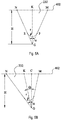
- Figure 5A is an enlarged projection of the groove 232 shown in Figure 2 on the normal plane in the direction of the rotation axis X, and is intended to show the specific structure of the groove 232.
- the shape of the groove 232 shown in Fig 5A is determined on the basis of one distribution point K in Fig. 4 .
- the projection of the trailing edge 220 of the blade 112 without grooves on the normal plane in the direction of the rotation axis X is a second curve, and the length of the second curve is L.
- the groove 232 has a groove wall NE, a groove wall MF and a groove bottom EF.
- a line connecting the distribution point K and point G is perpendicular to the tangent to the contour line 402 at the distribution point K.
- the line connecting the distribution point K and point G forms the groove depth H.
- the groove bottom EF is arc-shaped, and is tangent to the groove wall NE and the groove wall MF at a point E and a point F respectively.
- a straight line perpendicular to the contour line 402 is drawn at the distribution point K, and the position of the bottom point G is determined according to the groove depth H.
- a groove wall line NG and a groove wall line MG form an included angle ⁇ , and the included angle ⁇ satisfies ⁇ ⁇ [10°, 110°].
- MN is the opening width of the groove 232.
- the groove bottom EF is arc-shaped, and has radius r.
- the groove bottom EF is tangent to the groove wall line NG and the groove wall line MG at points E and F, respectively, thereby forming the groove wall NE and groove wall MF.
- the radius r satisfies r ⁇ 1 25 H , 1 5 H .
- Fig. 5B is a schematic drawing of the specific structure of the groove 232 in another embodiment of the present application.
- the groove 232 shown in Fig. 5B is substantially the same as the groove 232 shown in Fig. 5A , so a superfluous description is not given here.
- a straight line perpendicular to the contour line 402 is drawn at a point C close to the distribution point K, and the position of the bottom point G is determined according to the groove depth H.
- a groove wall line NG and a groove wall line MG form an included angle ⁇ , and the included angle ⁇ satisfies ⁇ ⁇ [10° ,110°].
- an offset angle ⁇ is formed between the straight line KG and the straight line CG; the offset angle ⁇ satisfies ⁇ ⁇ [0° ,15°].
- Point C may be at the left side of point K, or at the right side of point K.
- the length of the trailing edge 220 between groove walls of adjacent grooves 232 is the same.
- the multiple grooves 232 are configured such that the groove depths H thereof increase progressively by equal increments from the blade root 218 to the blade tip 216.
- the groove 232 closest to the blade tip 216 is configured such that the included angle ⁇ satisfies ⁇ [80° ,110°].
- the grooves 232 at the trailing edge 220 in the present application can reduce the power consumption of the blade 112.
- Fig. 6 is a side view of one of the blades 112 and the hub 110 in Fig. 1 , and is intended to show the specific structure of the blade tip 216.
- Fig. 7 is a simplified diagram showing the relationship of a blade tip trailing part 610 shown in Fig. 6 to a blade tip base part 612.
- the blade tip 216 comprises the blade tip base part 612 and the blade tip trailing part 610.
- the blade tip base part 612 and the blade tip trailing part 610 are smoothly connected, such that the blade 112 extends smoothly from the leading edge 222 to the trailing edge 220, and extends smoothly from the blade tip 216 to the blade root 218.
- the blade tip trailing part 610 is bent upwards relative to the blade tip base part 612. Specifically, a straight line connecting two ends of the blade tip base part 612 is a chord L1. A straight line connecting two ends of the blade tip trailing part 610 is a chord L2. An acute included angle between the chord and the normal plane perpendicular to the rotation axis X is an angle of attack ⁇ . The angle of attack ⁇ 2 of the chord L2 of the blade tip trailing part 610 is greater than the angle of attack ⁇ 1 of the chord L1 of the blade tip base part 612.
- the upward-bent structure of the blade tip trailing part 610 of the blade 112 has the advantage of reducing blade noise while increasing blade air volume.
- the inventors of the present application have found that in a conventional blade, when the blade rotates, vortices on the blade will be shed from the trailing edge. This rapid shedding of vortices will increase the vortex intensity, thereby causing an increase in noise.
- the upward-bent structure of the blade tip trailing part 610 is disposed close to the trailing edge 220, and will not cause an adverse effect whereby the leading edge 222 has a large load while the trailing edge 220 has a small load.
- the blade tip trailing part 610 close to the trailing edge 220 has maximum tangential speed (the speed in a direction perpendicular to the radial direction), and can split vortices at the trailing edge 220 so as to form smaller vortices, thereby delaying the shedding of vortices on the lower surface 244. This splitting into small vortices can effectively reduce noise and also improve sound quality.
- the upward-bent structure of the blade tip trailing part 610 can increase the work angle of the blade 112 while causing virtually no additional force to the blade 112, and thereby increase the work done by the blade 112, so as to increase the air volume of the blade 112 and increase the static pressure.
- the multiple grooves 232 mentioned above are also provided at the trailing edge 220.
- the technical effect achieved by the grooves 232 will be added to the technical effect achieved by the blade tip trailing part 610, so that the air volume of the blade 112 can still be increased while reducing the work done by the blade 112.
- either the upward-bent structure or the grooves may be provided alone.
- the proportion of the length of the blade tip 216 taken up by the length of the blade tip trailing part 610 is greater than or equal to 1/12 and less than or equal to 1/8.
- the angle of attack ⁇ 1 of the chord L1 of the blade tip trailing part 610 satisfies: ⁇ 1 ⁇ [20° ,30°].
- Fig. 8A is a top view of one of the blades 112 and the hub 110 in Fig. 1 .
- Fig. 8B is a section taken along a centre line A-A of the blade 112 and hub 110 in Fig. 8A . It can be seen from Figs. 8A - 8B that the blade tip 216 of the blade 112 has the blade tip trailing part 610. The upper surface 242 of the blade 112 extends smoothly from the blade root 218 to the blade tip 216.
- Fig. 9 is a sectional drawing of the trailing edge 220 of the blade 112 in a circumferential direction.
- Fig. 9 shows a sectional drawing of the trailing edge 220 within the circle in Fig. 6 in the circumferential direction.
- the trailing edge 220 and the lower surface 244 form a bevel.
- the upper surface 242 extends further than the lower surface 244.
- the trailing edge 220 connects the upper surface 242 and the lower surface 244, and the trailing edge 220 is smoothly connected to the lower surface 244.
- a circumferential section of the trailing edge 220 is arc-shaped.
- the inventors of the present application have found that, compared with a conventional blade having a trailing edge and lower surface that do not form a bevel, the efficiency of a blade 112 having a trailing edge 220 that forms a bevel with the lower surface 244 can be increased by about 4%, and noise can be reduced by about 12%.
- Figure 10 is a graph of the relationship between static pressure and air volume, for the blade 112 of the present application and a conventional blade. It can be seen from Fig. 10 that, for the same air volume, the static pressure of the blade of the present application is higher than the static pressure of the conventional blade by approximately 60 pa, so the blade of the present application can satisfy application scenarios with higher static pressure requirements.
- Figure 11 is a graph of the relationship between efficiency and air volume, for the blade 112 of the present application and a conventional blade. It is clear from Figure 11 that for the same air volume, the efficiency of the blade of the present application is higher than that of the conventional blade. In particular when the air volume increases, the efficiency of the blade 112 of the present application does not fall by much, whereas the efficiency of the conventional blade falls more quickly.
- Figure 12 is a graph of the relationship between noise and air volume, for the blade 112 of the present application and a conventional blade. It is clear from Figure 12 that for the same air volume, the noise of the blade of the present application is lower than that of the conventional blade. In addition, the noise sound quality produced by the blade 112 of the present application is superior to that produced by the conventional blade.
- the range of air volumes that the blade 112 of the present application is able to provide is higher, specifically 17000 m 3 /h - 23000 m 3 /h, so the blade of the present application can satisfy application scenarios with higher air volume requirements.
- a blade profile cross section of the blade 112 from the leading edge to the trailing edge may be of various types; it may be a cross section of equal thickness or any two-dimensional airfoil profile.
Landscapes
- Engineering & Computer Science (AREA)
- Mechanical Engineering (AREA)
- General Engineering & Computer Science (AREA)
- Structures Of Non-Positive Displacement Pumps (AREA)
Abstract
Disclosed in the present application is a blade and an axial flow impeller using same. The blade comprises a blade tip, a blade root, a leading edge, a trailing edge, an upper surface and a lower surface. The upper surface and lower surface are disposed opposite each other; the blade tip, the blade root, the leading edge and the trailing edge surround the upper surface and the lower surface, and connect the upper surface and the lower surface. The blade is rotatable about a rotation axis, the rotation axis being perpendicular to a normal plane. The blade tip comprises a blade tip base part and a blade tip trailing part, the blade tip base part being close to the leading edge, and the blade tip trailing part being close to the trailing edge and being bent upwards relative to the blade tip base part. An angle of attack of a chord of the blade tip trailing part is greater than an angle of attack of a chord of the blade tip base part, wherein the angle of attack is an acute included angle between the chord and the normal plane. The blade of the present application can provide a large air volume, and has higher static pressure and higher efficiency.
Description
- The present application relates to the field of rotary machinery such as fans, pumps and compressors, in particular to a blade and an axial flow impeller using same.
- The leading edge and trailing edge of a conventional blade are generally monotonous, smooth curves. Due to serious flow separation at the surface of the blade, vortices are formed, and consequently the blade has low aerodynamic performance and high noise.
- Exemplary embodiments of the present application can solve at least some of the above-mentioned problems.
- According to a first aspect of the present application, the present application provides a blade, comprising a blade tip, a blade root, a leading edge, a trailing edge, an upper surface and a lower surface. The upper surface and lower surface are disposed opposite each other; the blade tip, the blade root, the leading edge and the trailing edge surround the upper surface and the lower surface, and connect the upper surface and the lower surface. The blade is rotatable about a rotation axis, the rotation axis being perpendicular to a normal plane. The blade tip comprises a blade tip base part and a blade tip trailing part, the blade tip base part being close to the leading edge, and the blade tip trailing part being close to the trailing edge and being bent upwards relative to the blade tip base part. An angle of attack of a chord of the blade tip trailing part is greater than an angle of attack of a chord of the blade tip base part, wherein the angle of attack is an acute included angle between the chord and the normal plane.
- In the blade according to the abovementioned first aspect, the upper surface extends smoothly from the blade tip to the blade root.
- In the blade according to the abovementioned first aspect, the range of values of the angle of attack of the chord of the blade tip trailing part is greater than or equal to 20° and less than or equal to 30°.
- In the blade according to the abovementioned first aspect, the proportion of the length of the blade tip taken up by the blade tip trailing part is greater than or equal to 1/12 and less than or equal to 1/8.
- In the blade according to the abovementioned first aspect, a projection of the leading edge on the normal plane in the direction of the rotation axis is a first curve, and the first curve has an even number of inflection points.
- In the blade according to the abovementioned first aspect, a line connecting any point on the first curve and the perpendicular foot is a first connecting line. A line connecting the perpendicular foot and a point of projection of the intersection point of the blade root and the leading edge on the normal plane in the direction of the rotation axis is a second connecting line. An included angle between the first connecting line and the second connecting line is called a leading edge angle θ. The leading edge angle θ of any point on the first curve satisfies θ∈[0°,20°].
- In the blade according to the abovementioned first aspect, the trailing edge is provided with multiple grooves, and a projection of the trailing edge on the normal plane in the direction of the rotation axis is a second curve, wherein an included angle between groove walls of each groove is α,a groove depth is H, and the length of the second curve is L.
- The included angle and the groove depth satisfy:


- In the blade according to the abovementioned first aspect, the in eluded angle α between the groove walls of the groove closest to the blade tip in the multiple grooves satisfies: α ∈ [80°,110°] .
- In the blade according to the abovementioned first aspect, the length of the trailing edge between groove walls of two adjacent said grooves is the same.
- In the blade according to the abovementioned first aspect, on the trailing edge of the blade, the upper surface of the blade extends further than the lower surface in a circumferential direction, and a cross section of the trailing edge in the circumferential direction of the blade is arc-shaped.
- According to a second aspect of the present application, the present application provides an axial flow impeller, comprising a hub and at least two blades according to the abovementioned first aspect. The hub has a rotation axis, the hub being rotatable about the rotation axis. The at least two blades are arranged on an outer circumferential face of the hub.
- The blade of the present application can provide a large air volume, and has higher static pressure and higher efficiency.
- The features and advantages of the present application can be better understood by reading the following detailed description with reference to the drawings. In all of the drawings, identical reference labels indicate identical components, wherein:
-
Figure 1 shows a three-dimensional drawing of an axial flow impeller using the blade in an embodiment of the present application. -
Figure 2 shows a three-dimensional drawing of the blade used in the axial flow impeller inFigure 1 . -
Figure 3 shows a projection of the blade inFigure 1 on a normal plane in the direction of a rotation axis X. -
Figure 4 is a projection, on the normal plane in the direction of the rotation axis X, of a blade whose trailing edge is not provided with multiple grooves. -
Figure 5A is an enlarged projection of the groove shown inFigure 2 on the normal plane in the direction of the rotation axis X. -
Figure 5B is a schematic drawing of the specific structure of the groove in another embodiment of the present application. -
Figure 6 is a side view of one of the blades and the hub inFigure 1 . -
Figure 7 is a simplified diagram showing the relationship of a blade tip trailing part shown inFigure 6 to a blade tip base part. -
Figure 8A is a top view of one of the blades and the hub inFigure 1 . -
Figure 8B is a section taken along a line A-A inFigure 8A . -
Figure 9 is a sectional drawing of the trailing edge of the blade in a circumferential direction. -
Figure 10 is a graph of the relationship between static pressure and air volume, for the blade of the present application and a conventional blade. -
Figure 11 is a graph of the relationship between efficiency and air volume, for the blade of the present application and a conventional blade. -
Figure 12 is a graph of the relationship between noise and air volume, for the blade of the present application and a conventional blade. - Various specific embodiments of the present application will be described below with reference to the drawings which form a part of this description. In the following drawings, identical parts and components are indicated by identical reference numerals.
-
Figure 1 shows a three-dimensional drawing of anaxial flow impeller 100 using the blade in an embodiment of the present application. As shown inFigure 1 , theaxial flow impeller 100 comprises ahub 110 and threeblades 112. Thehub 110 has a rotation axis X; a cross section of thehub 110 perpendicular to the rotation axis X is circular. The threeblades 112 are evenly arranged on an outer circumferential face of thehub 110, and are integrally connected to thehub 110. Thehub 110 and theblades 112 may rotate about the rotation axis X together. As an example, theaxial flow impeller 100 of the present application rotates around the rotation axis X clockwise (that is, in the rotation direction indicated by the arrow inFigure 1 ). Those of ordinary skill in the art can understand that thehub 110 may also have another shape, and the number ofblades 112 may be at least two. Thehub 110 may be shaped in accordance with the number ofblades 112. For example, when the number ofblades 112 is three, the cross section of thehub 110 perpendicular to the rotation axis X is triangular; when the number ofblades 112 is four, the cross section of thehub 110 perpendicular to the rotation axis X is quadrilateral. -
Figure 2 shows a three-dimensional drawing of theblade 112 used in theaxial flow impeller 100 inFigure 1 . As shown inFigure 2 , theblade 112 comprises anupper surface 242, alower surface 244, ablade tip 216, ablade root 218, a leadingedge 222 and atrailing edge 220. Theupper surface 242 andlower surface 244 are disposed opposite each other. "Leading edge 222" refers to the front-end edge in the direction of blade rotation. "Trailing edge 220" refers to the rear-end edge in the direction of blade rotation. "Blade root 218" refers to an edge where the blade and the hub intersect. "Blade tip 216" refers to the other edge opposite the blade root. Theblade tip 216,blade root 218, leadingedge 222 and trailingedge 220 surround theupper surface 242 and thelower surface 244. That is to say, theupper surface 242 and thelower surface 244 each extend from theblade tip 216 to theblade root 218, and also each extend from theleading edge 222 to the trailingedge 220. The trailingedge 220 of theblade 112 of the present application is provided withmultiple grooves 232, each of themultiple grooves 232 extending towards the leadingedge 222. - The
axial flow impeller 100 has a normal plane (not shown) that is perpendicular to the rotation axis X, and the rotation axis X and the normal plane perpendicularly intersect at the perpendicular foot O (seeFigure 3 ). Those of ordinary skill in the art can understand that the normal plane is a virtual plane intended to better illustrate the specific structure of theblade 112. -
Figure 3 shows a projection of theblade 112 inFigure 1 on the normal plane in the direction of the rotation axis X. A projection of theleading edge 222 of theblade 112 on the normal plane in the direction of the rotation axis X is a first curve, wherein the first curve has two inflection points a and b. The inflection points are demarcation points between concave arcs and convex arcs. - As shown in
Figure 3 , the first curve has two inflection points: inflection point a and inflection point b. A point of projection of the intersection point of theblade root 218 and theleading edge 222 on the normal plane in the direction of the rotation axis X is a point A, and a point of projection of the intersection point of theblade tip 216 and theleading edge 222 on the normal plane in the direction of the rotation axis X is a point B. The curve from point A to inflection point a and the curve from inflection point b to point B are concave arcs; the curve from inflection point a to inflection point b is a convex arc. A point P is any point on the first curve, and a line connecting point P and the perpendicular foot O is a first connecting line. A line connecting point A and the perpendicular foot O is a second connecting line. An included angle between the first connecting line and the second connecting line is a leading edge angle θ. In an embodiment of the present application, the leading edge angle θ of any point P on the first curve satisfies θ ∈ [0° ,20°], and the line connecting any point P on the first curve and the perpendicular foot O is on the same side of the second connecting line. - Those skilled in the art will understand that the first curve in the present application can have any even number of inflection points, with no restriction to the two inflection points shown in the present application.
- The inventors of the present application have found that when the leading edge angle θ satisfies θ ∈ [0° ,20°], the work length of the
leading edge 222 having the concave arcs and convex arc can be increased effectively, thereby reducing the load on theleading edge 222 of theblade 112. When theblade 112 rotates, the concave arcs and convex arc on theleading edge 222 can forcibly split a large shed vortex that originally gathered on the upper surface of theblade 112 near theleading edge 222 into multiple small vortices, and as theblade 112 rotates, this causes the multiple small vortices to be located in a middle region of theblade 112 and at positions close to the trailingedge 220. Thus, the multiple small shed vortices located in the middle region of theblade 112 and at positions close to the trailingedge 220 can effectively reduce the intensity of turbulence as well as dissipation losses caused by turbulence, thus improving aerodynamic performance. As an example, the static efficiency value of a conventional blade is about 40%, whereas the static efficiency value of theblade 112 of the present application can reach 50%; this can effectively improve aerodynamic performance by 25%. In addition, when the multiple small vortices produced by splitting are flowing towards the trailingedge 220, they are not prone to mutual movement in the radial direction of theblade 112 to cause secondary flows, and relative speed flow lines of air on the surface of theblade 112 cross over each other as little as possible; thus, at the same time as the aerodynamic performance is improved, it is also possible to reduce noise. As an example, theblade 112 of the present application can reduce the noise value by 4 dB compared with a conventional blade (a reduction of 13%). -
Figure 4 is a projection, on the normal plane in the direction of the rotation axis X, of ablade 112 whose trailingedge 220 is not provided withmultiple grooves 232, and is intended to show multiple distribution points K ofgrooves 232.Multiple grooves 232 are provided according to the positions of the multiple distribution points K, thereby obtaining theblade 112 ofFig. 3 , which hasmultiple grooves 232 provided on the trailingedge 220. As shown inFigure 4 , the trailingedge 220 has acontour line 402. The trailingedge 220 is provided withmultiple grooves 232, each groove has a distribution point K, and the distribution point K of each groove is located on thecontour line 402. -
Figure 5A is an enlarged projection of thegroove 232 shown inFigure 2 on the normal plane in the direction of the rotation axis X, and is intended to show the specific structure of thegroove 232. The shape of thegroove 232 shown inFig 5A is determined on the basis of one distribution point K inFig. 4 . As shown inFigure 4 , the projection of the trailingedge 220 of theblade 112 without grooves on the normal plane in the direction of the rotation axis X is a second curve, and the length of the second curve is L. Thegroove 232 has a groove wall NE, a groove wall MF and a groove bottom EF. Lines of extension of the groove wall NE and groove wall MF intersect at a point G, and the groove wall NE and groove wall MF form an included angle α. A line connecting the distribution point K and point G is perpendicular to the tangent to thecontour line 402 at the distribution point K. The line connecting the distribution point K and point G forms the groove depth H. The groove bottom EF is arc-shaped, and is tangent to the groove wall NE and the groove wall MF at a point E and a point F respectively. - As an example, a straight line perpendicular to the
contour line 402 is drawn at the distribution point K, and the position of the bottom point G is determined according to the groove depth H. The groove depth H satisfies:
- A groove wall line NG and a groove wall line MG form an included angle α, and the included angle α satisfies α ∈ [10°, 110°].
- MN is the opening width of the
groove 232. The groove bottom EF is arc-shaped, and has radius r. The groove bottom EF is tangent to the groove wall line NG and the groove wall line MG at points E and F, respectively, thereby forming the groove wall NE and groove wall MF. The radius r satisfies
-
Fig. 5B is a schematic drawing of the specific structure of thegroove 232 in another embodiment of the present application. Thegroove 232 shown inFig. 5B is substantially the same as thegroove 232 shown inFig. 5A , so a superfluous description is not given here. Unlike thegroove 232 shown inFig. 5A , a straight line perpendicular to thecontour line 402 is drawn at a point C close to the distribution point K, and the position of the bottom point G is determined according to the groove depth H. The groove depth H satisfies:
- A groove wall line NG and a groove wall line MG form an included angle α, and the included angle α satisfies α ∈ [10° ,110°].
- In addition, an offset angle Ω is formed between the straight line KG and the straight line CG; the offset angle Ω satisfies Ω ∈ [0° ,15°]. Point C may be at the left side of point K, or at the right side of point K.
- As an example, the length of the trailing
edge 220 between groove walls ofadjacent grooves 232 is the same. - As another example, the
multiple grooves 232 are configured such that the groove depths H thereof increase progressively by equal increments from theblade root 218 to theblade tip 216. - Continuing to refer to
Fig. 3 , in the present application, thegroove 232 closest to theblade tip 216 is configured such that the included angle α satisfies α [80° ,110°]. - The
grooves 232 at the trailingedge 220 in the present application can reduce the power consumption of theblade 112. -
Fig. 6 is a side view of one of theblades 112 and thehub 110 inFig. 1 , and is intended to show the specific structure of theblade tip 216.Fig. 7 is a simplified diagram showing the relationship of a bladetip trailing part 610 shown inFig. 6 to a bladetip base part 612. As shown inFigures 6 - 7 , theblade tip 216 comprises the bladetip base part 612 and the bladetip trailing part 610. The bladetip base part 612 and the bladetip trailing part 610 are smoothly connected, such that theblade 112 extends smoothly from theleading edge 222 to the trailingedge 220, and extends smoothly from theblade tip 216 to theblade root 218. That is to say, there is no inflection point between the bladetip base part 612 and the bladetip trailing part 610. The bladetip trailing part 610 is bent upwards relative to the bladetip base part 612. Specifically, a straight line connecting two ends of the bladetip base part 612 is a chord L1. A straight line connecting two ends of the bladetip trailing part 610 is a chord L2. An acute included angle between the chord and the normal plane perpendicular to the rotation axis X is an angle of attack §. The angle of attack §2 of the chord L2 of the bladetip trailing part 610 is greater than the angle of attack §1 of the chord L1 of the bladetip base part 612. - In the present application, the upward-bent structure of the blade
tip trailing part 610 of theblade 112 has the advantage of reducing blade noise while increasing blade air volume. Specifically, the inventors of the present application have found that in a conventional blade, when the blade rotates, vortices on the blade will be shed from the trailing edge. This rapid shedding of vortices will increase the vortex intensity, thereby causing an increase in noise. In theblade 112 of the present application, the upward-bent structure of the bladetip trailing part 610 is disposed close to the trailingedge 220, and will not cause an adverse effect whereby theleading edge 222 has a large load while the trailingedge 220 has a small load. The bladetip trailing part 610 close to the trailingedge 220 has maximum tangential speed (the speed in a direction perpendicular to the radial direction), and can split vortices at the trailingedge 220 so as to form smaller vortices, thereby delaying the shedding of vortices on thelower surface 244. This splitting into small vortices can effectively reduce noise and also improve sound quality. - In addition, the upward-bent structure of the blade
tip trailing part 610 can increase the work angle of theblade 112 while causing virtually no additional force to theblade 112, and thereby increase the work done by theblade 112, so as to increase the air volume of theblade 112 and increase the static pressure. - It must be explained that while the upward-bent structure of the blade
tip trailing part 610 is provided on theblade 112 of the present application, themultiple grooves 232 mentioned above are also provided at the trailingedge 220. In this case, the technical effect achieved by thegrooves 232 will be added to the technical effect achieved by the bladetip trailing part 610, so that the air volume of theblade 112 can still be increased while reducing the work done by theblade 112. In other embodiments, either the upward-bent structure or the grooves may be provided alone. - As an example, the proportion of the length of the
blade tip 216 taken up by the length of the bladetip trailing part 610 is greater than or equal to 1/12 and less than or equal to 1/8. - As another example, the angle of attack §1 of the chord L1 of the blade
tip trailing part 610 satisfies: §1 ∈ [20° ,30°]. -
Fig. 8A is a top view of one of theblades 112 and thehub 110 inFig. 1 .Fig. 8B is a section taken along a centre line A-A of theblade 112 andhub 110 inFig. 8A . It can be seen fromFigs. 8A - 8B that theblade tip 216 of theblade 112 has the bladetip trailing part 610. Theupper surface 242 of theblade 112 extends smoothly from theblade root 218 to theblade tip 216. -
Fig. 9 is a sectional drawing of the trailingedge 220 of theblade 112 in a circumferential direction. As an example,Fig. 9 shows a sectional drawing of the trailingedge 220 within the circle inFig. 6 in the circumferential direction. As shown inFig. 9 , the trailingedge 220 and thelower surface 244 form a bevel. Specifically, theupper surface 242 extends further than thelower surface 244. The trailingedge 220 connects theupper surface 242 and thelower surface 244, and the trailingedge 220 is smoothly connected to thelower surface 244. As an example, a circumferential section of the trailingedge 220 is arc-shaped. - The inventors of the present application have found that, compared with a conventional blade having a trailing edge and lower surface that do not form a bevel, the efficiency of a
blade 112 having a trailingedge 220 that forms a bevel with thelower surface 244 can be increased by about 4%, and noise can be reduced by about 12%. -
Figure 10 is a graph of the relationship between static pressure and air volume, for theblade 112 of the present application and a conventional blade. It can be seen fromFig. 10 that, for the same air volume, the static pressure of the blade of the present application is higher than the static pressure of the conventional blade by approximately 60 pa, so the blade of the present application can satisfy application scenarios with higher static pressure requirements. -
Figure 11 is a graph of the relationship between efficiency and air volume, for theblade 112 of the present application and a conventional blade. It is clear fromFigure 11 that for the same air volume, the efficiency of the blade of the present application is higher than that of the conventional blade. In particular when the air volume increases, the efficiency of theblade 112 of the present application does not fall by much, whereas the efficiency of the conventional blade falls more quickly. -
Figure 12 is a graph of the relationship between noise and air volume, for theblade 112 of the present application and a conventional blade. It is clear fromFigure 12 that for the same air volume, the noise of the blade of the present application is lower than that of the conventional blade. In addition, the noise sound quality produced by theblade 112 of the present application is superior to that produced by the conventional blade. - Moreover, it can also be seen from
Figs. 10 - 12 that for the same input power, the range of air volumes that theblade 112 of the present application is able to provide is higher, specifically 17000 m3/h - 23000 m3/h, so the blade of the present application can satisfy application scenarios with higher air volume requirements. - It must be explained that a blade profile cross section of the
blade 112 from the leading edge to the trailing edge may be of various types; it may be a cross section of equal thickness or any two-dimensional airfoil profile. - Although only some characteristics of the present application are shown and described herein, those skilled in the art can make various improvements and modifications. Therefore, it should be understood that the attached claims are intended to cover all of the abovementioned improvements and modifications falling within the scope of the substantive spirit of the present application.
Claims (10)
- Blade (112), comprising:- a blade tip (216), a blade root (218), a leading edge (222), a trailing edge (220), an upper surface (242) and a lower surface (244), the upper surface (242) and lower surface (244) being disposed opposite each other; the blade tip (216), the blade root (218), the leading edge (222) and the trailing edge (220) surrounding the upper surface (242) and the lower surface (244), and connecting the upper surface (242) and the lower surface (244); and the blade (112) being rotatable about a rotation axis (X), the rotation axis (X) being perpendicular to a normal plane;characterized in that:the blade tip (216) comprises a blade tip base part (612) and a blade tip trailing part (610), the blade tip base part (612) being close to the leading edge (222), and the blade tip trailing part (610) being close to the trailing edge (220) and being bent upwards relative to the blade tip base part (612);wherein an angle of attack of a chord of the blade tip trailing part (610) is greater than an angle of attack of a chord of the blade tip base part (612), wherein the angle of attack is an acute included angle between the chord and the normal plane.
- Blade (112) according to Claim 1,
characterized in that:- the upper surface (242) extends smoothly from the blade tip (216) to the blade root (218). - Blade (112) according to Claim 1 or 2,
characterized in that:- the range of values of the angle of attack of the chord of the blade tip trailing part (610) is greater than or equal to 20° and less than or equal to 30°. - Blade (112) according to any of the Claims 1 to 3,
characterized in that:- the proportion of the length of the blade tip (216) taken up by the blade tip trailing part (610) is greater than or equal to 1/12 and less than or equal to 1/8. - Blade (112) according to any of the Claims 1 to 4,
characterized in that:- a projection of the leading edge (222) on the normal plane in the direction of the rotation axis (X) is a first curve, and the first curve has an even number of inflection points;- the rotation axis (X) and the normal plane perpendicularly intersect at a perpendicular foot (O);- a line connecting any point on the first curve and the perpendicular foot (O) is a first connecting line;- a line connecting the perpendicular foot (O) and a point of projection (A) of the intersection point of the blade root (218) and the leading edge (222) on the normal plane in the direction of the rotation axis (X) is a second connecting line;- an included angle between the first connecting line and the second connecting line is called a leading edge angle θ; and- the leading edge angle θ of any point on the first curve satisfies θ ∈ [0°, 20°]. - Blade (112) according to any of the Claims 1 to 5,
characterized in that:- the trailing edge (220) is provided with multiple grooves (232), and a projection of the trailing edge (220) on the normal plane in the direction of the rotation axis (X) is a second curve, wherein an included angle between groove walls of each groove is α, a groove depth is H, and the length of the second curve is L;- the included angle and the groove depth satisfy, respectively:

- Blade (112) according to Claim 6,
characterized in that:- the included angle α between the groove walls of the groove closest to the blade tip (216) in the multiple grooves (232) satisfies: α ∈ [80°, 110°]. - Blade (112) according to Claim 6 or 7,
characterized in that:- the length of the trailing edge (220) between groove walls of two adjacent said grooves (232) is the same. - Blade (112) according to any of the Claims 1 to 8,
characterized in that:- on the trailing edge (220) of the blade (112), the upper surface of the blade (112) extends further than the lower surface in a circumferential direction, and a cross section of the trailing edge (220) in the circumferential direction of the blade (112) is arc-shaped. - Axial flow impeller (100), characterized by comprising:- a hub (110), the hub (110) having a rotation axis (X), the hub (110) being rotatable about the rotation axis (X); and- at least two blades (112) according to any one of Claims 1 to 9, the at least two blades (112) being arranged on an outer circumferential face of the hub (110).
Applications Claiming Priority (1)
| Application Number | Priority Date | Filing Date | Title |
|---|---|---|---|
| CN202010290698.0A CN111577656B (en) | 2020-04-14 | 2020-04-14 | Blade and axial flow impeller using same |
Publications (1)
| Publication Number | Publication Date |
|---|---|
| EP3896291A1 true EP3896291A1 (en) | 2021-10-20 |
Family
ID=72123537
Family Applications (1)
| Application Number | Title | Priority Date | Filing Date |
|---|---|---|---|
| EP21167369.4A Pending EP3896291A1 (en) | 2020-04-14 | 2021-04-08 | Blade and axial flow impeller using same |
Country Status (3)
| Country | Link |
|---|---|
| US (1) | US11608835B2 (en) |
| EP (1) | EP3896291A1 (en) |
| CN (1) | CN111577656B (en) |
Families Citing this family (1)
| Publication number | Priority date | Publication date | Assignee | Title |
|---|---|---|---|---|
| CN120576112A (en) * | 2024-03-01 | 2025-09-02 | 台达电子工业股份有限公司 | Axial flow fan |
Citations (5)
| Publication number | Priority date | Publication date | Assignee | Title |
|---|---|---|---|---|
| CN201241864Y (en) * | 2008-08-15 | 2009-05-20 | 新昌县科贸实业有限公司 | Wind impeller for fan |
| US20120207606A1 (en) * | 2010-08-13 | 2012-08-16 | Ziehl-Abegg Ag | Impeller Wheel for a Ventilator |
| CN104389817A (en) * | 2014-11-05 | 2015-03-04 | 广东佳科风机股份有限公司 | Surging-reduction low-noise blower impeller with adjustable blade angle |
| JP2017070337A (en) * | 2015-10-05 | 2017-04-13 | 日立マクセル株式会社 | Blower |
| CN110939603A (en) * | 2018-09-25 | 2020-03-31 | 约克广州空调冷冻设备有限公司 | Blade and axial flow impeller using same |
Family Cites Families (5)
| Publication number | Priority date | Publication date | Assignee | Title |
|---|---|---|---|---|
| CN202326414U (en) * | 2011-11-21 | 2012-07-11 | 珠海格力电器股份有限公司 | Axial flow fan |
| CN203717440U (en) * | 2014-02-08 | 2014-07-16 | 美的集团股份有限公司 | Axial fan |
| CN105041684A (en) * | 2015-08-07 | 2015-11-11 | 黄社兰 | Engineering axial flow cooling plastic fan |
| DE102015216579A1 (en) * | 2015-08-31 | 2017-03-02 | Ziehl-Abegg Se | Fan, fan and system with at least one fan |
| AU2017206193B2 (en) * | 2016-09-02 | 2023-07-27 | Fujitsu General Limited | Axial fan and outdoor unit |
-
2020
- 2020-04-14 CN CN202010290698.0A patent/CN111577656B/en active Active
-
2021
- 2021-04-08 EP EP21167369.4A patent/EP3896291A1/en active Pending
- 2021-04-13 US US17/229,662 patent/US11608835B2/en active Active
Patent Citations (5)
| Publication number | Priority date | Publication date | Assignee | Title |
|---|---|---|---|---|
| CN201241864Y (en) * | 2008-08-15 | 2009-05-20 | 新昌县科贸实业有限公司 | Wind impeller for fan |
| US20120207606A1 (en) * | 2010-08-13 | 2012-08-16 | Ziehl-Abegg Ag | Impeller Wheel for a Ventilator |
| CN104389817A (en) * | 2014-11-05 | 2015-03-04 | 广东佳科风机股份有限公司 | Surging-reduction low-noise blower impeller with adjustable blade angle |
| JP2017070337A (en) * | 2015-10-05 | 2017-04-13 | 日立マクセル株式会社 | Blower |
| CN110939603A (en) * | 2018-09-25 | 2020-03-31 | 约克广州空调冷冻设备有限公司 | Blade and axial flow impeller using same |
Also Published As
| Publication number | Publication date |
|---|---|
| CN111577656B (en) | 2021-11-05 |
| US20210317841A1 (en) | 2021-10-14 |
| US11608835B2 (en) | 2023-03-21 |
| CN111577656A (en) | 2020-08-25 |
Similar Documents
| Publication | Publication Date | Title |
|---|---|---|
| CN111577655B (en) | Blade and axial flow impeller using same | |
| JP3876195B2 (en) | Centrifugal compressor impeller | |
| US4231706A (en) | Impeller of a centrifugal blower | |
| CN106121734B (en) | Blade, gas turbine comprising such a blade, and method for manufacturing such a blade | |
| CN108506247B (en) | Blade and axial flow impeller using same | |
| CA2934764A1 (en) | A rotor with a leading edge protrusion | |
| JP2012052443A (en) | Propeller fan | |
| EP3896291A1 (en) | Blade and axial flow impeller using same | |
| US11572890B2 (en) | Blade and axial flow impeller using same | |
| CN110939603A (en) | Blade and axial flow impeller using same | |
| CN209012127U (en) | Blade and the axial wheel for using it | |
| CN114901922B (en) | turbine blades | |
| US20250382971A1 (en) | Blade and axial impeller using same | |
| JP2022056022A (en) | Propeller fan | |
| EP3760875B1 (en) | Rotor and centrifugal compression machine provided with said rotor | |
| CN112943688B (en) | Impeller | |
| US11519422B2 (en) | Blade and axial flow impeller using same | |
| JPH03267506A (en) | Axial flow turbine stator blade | |
| CA2436670A1 (en) | Hydraulic turbine with interblade vortex suppressor | |
| KR100326997B1 (en) | Axial flow fan | |
| CN114151383B (en) | Axial flow fan blade, axial flow fan and air conditioner | |
| US20240084813A1 (en) | Fan | |
| CN120906844A (en) | Blade and axial flow impeller using same | |
| WO2018135093A1 (en) | Rotor | |
| US20220120190A1 (en) | Nozzle vane |
Legal Events
| Date | Code | Title | Description |
|---|---|---|---|
| PUAI | Public reference made under article 153(3) epc to a published international application that has entered the european phase |
Free format text: ORIGINAL CODE: 0009012 |
|
| STAA | Information on the status of an ep patent application or granted ep patent |
Free format text: STATUS: REQUEST FOR EXAMINATION WAS MADE |
|
| 17P | Request for examination filed |
Effective date: 20210408 |
|
| AK | Designated contracting states |
Kind code of ref document: A1 Designated state(s): AL AT BE BG CH CY CZ DE DK EE ES FI FR GB GR HR HU IE IS IT LI LT LU LV MC MK MT NL NO PL PT RO RS SE SI SK SM TR |
|
| B565 | Issuance of search results under rule 164(2) epc |
Effective date: 20210913 |
|
| STAA | Information on the status of an ep patent application or granted ep patent |
Free format text: STATUS: EXAMINATION IS IN PROGRESS |
|
| 17Q | First examination report despatched |
Effective date: 20230322 |