EP3896282A1 - Thermally driven elastocaloric system - Google Patents
Thermally driven elastocaloric system Download PDFInfo
- Publication number
- EP3896282A1 EP3896282A1 EP21164985.0A EP21164985A EP3896282A1 EP 3896282 A1 EP3896282 A1 EP 3896282A1 EP 21164985 A EP21164985 A EP 21164985A EP 3896282 A1 EP3896282 A1 EP 3896282A1
- Authority
- EP
- European Patent Office
- Prior art keywords
- sma member
- sma
- connection mechanism
- heat
- potential
- Prior art date
- Legal status (The legal status is an assumption and is not a legal conclusion. Google has not performed a legal analysis and makes no representation as to the accuracy of the status listed.)
- Pending
Links
Images



Classifications
-
- F—MECHANICAL ENGINEERING; LIGHTING; HEATING; WEAPONS; BLASTING
- F03—MACHINES OR ENGINES FOR LIQUIDS; WIND, SPRING, OR WEIGHT MOTORS; PRODUCING MECHANICAL POWER OR A REACTIVE PROPULSIVE THRUST, NOT OTHERWISE PROVIDED FOR
- F03G—SPRING, WEIGHT, INERTIA OR LIKE MOTORS; MECHANICAL-POWER PRODUCING DEVICES OR MECHANISMS, NOT OTHERWISE PROVIDED FOR OR USING ENERGY SOURCES NOT OTHERWISE PROVIDED FOR
- F03G7/00—Mechanical-power-producing mechanisms, not otherwise provided for or using energy sources not otherwise provided for
- F03G7/06—Mechanical-power-producing mechanisms, not otherwise provided for or using energy sources not otherwise provided for using expansion or contraction of bodies due to heating, cooling, moistening, drying or the like
- F03G7/065—Mechanical-power-producing mechanisms, not otherwise provided for or using energy sources not otherwise provided for using expansion or contraction of bodies due to heating, cooling, moistening, drying or the like using a shape memory element
-
- F—MECHANICAL ENGINEERING; LIGHTING; HEATING; WEAPONS; BLASTING
- F03—MACHINES OR ENGINES FOR LIQUIDS; WIND, SPRING, OR WEIGHT MOTORS; PRODUCING MECHANICAL POWER OR A REACTIVE PROPULSIVE THRUST, NOT OTHERWISE PROVIDED FOR
- F03G—SPRING, WEIGHT, INERTIA OR LIKE MOTORS; MECHANICAL-POWER PRODUCING DEVICES OR MECHANISMS, NOT OTHERWISE PROVIDED FOR OR USING ENERGY SOURCES NOT OTHERWISE PROVIDED FOR
- F03G7/00—Mechanical-power-producing mechanisms, not otherwise provided for or using energy sources not otherwise provided for
- F03G7/06—Mechanical-power-producing mechanisms, not otherwise provided for or using energy sources not otherwise provided for using expansion or contraction of bodies due to heating, cooling, moistening, drying or the like
- F03G7/061—Mechanical-power-producing mechanisms, not otherwise provided for or using energy sources not otherwise provided for using expansion or contraction of bodies due to heating, cooling, moistening, drying or the like characterised by the actuating element
- F03G7/0614—Mechanical-power-producing mechanisms, not otherwise provided for or using energy sources not otherwise provided for using expansion or contraction of bodies due to heating, cooling, moistening, drying or the like characterised by the actuating element using shape memory elements
-
- F—MECHANICAL ENGINEERING; LIGHTING; HEATING; WEAPONS; BLASTING
- F03—MACHINES OR ENGINES FOR LIQUIDS; WIND, SPRING, OR WEIGHT MOTORS; PRODUCING MECHANICAL POWER OR A REACTIVE PROPULSIVE THRUST, NOT OTHERWISE PROVIDED FOR
- F03G—SPRING, WEIGHT, INERTIA OR LIKE MOTORS; MECHANICAL-POWER PRODUCING DEVICES OR MECHANISMS, NOT OTHERWISE PROVIDED FOR OR USING ENERGY SOURCES NOT OTHERWISE PROVIDED FOR
- F03G7/00—Mechanical-power-producing mechanisms, not otherwise provided for or using energy sources not otherwise provided for
- F03G7/06—Mechanical-power-producing mechanisms, not otherwise provided for or using energy sources not otherwise provided for using expansion or contraction of bodies due to heating, cooling, moistening, drying or the like
- F03G7/062—Mechanical-power-producing mechanisms, not otherwise provided for or using energy sources not otherwise provided for using expansion or contraction of bodies due to heating, cooling, moistening, drying or the like characterised by the activation arrangement
-
- F—MECHANICAL ENGINEERING; LIGHTING; HEATING; WEAPONS; BLASTING
- F25—REFRIGERATION OR COOLING; COMBINED HEATING AND REFRIGERATION SYSTEMS; HEAT PUMP SYSTEMS; MANUFACTURE OR STORAGE OF ICE; LIQUEFACTION SOLIDIFICATION OF GASES
- F25B—REFRIGERATION MACHINES, PLANTS OR SYSTEMS; COMBINED HEATING AND REFRIGERATION SYSTEMS; HEAT PUMP SYSTEMS
- F25B23/00—Machines, plants or systems, with a single mode of operation not covered by groups F25B1/00 - F25B21/00, e.g. using selective radiation effect
-
- F—MECHANICAL ENGINEERING; LIGHTING; HEATING; WEAPONS; BLASTING
- F05—INDEXING SCHEMES RELATING TO ENGINES OR PUMPS IN VARIOUS SUBCLASSES OF CLASSES F01-F04
- F05C—INDEXING SCHEME RELATING TO MATERIALS, MATERIAL PROPERTIES OR MATERIAL CHARACTERISTICS FOR MACHINES, ENGINES OR PUMPS OTHER THAN NON-POSITIVE-DISPLACEMENT MACHINES OR ENGINES
- F05C2251/00—Material properties
- F05C2251/08—Shape memory
Definitions
- the invention relates to a thermally driven elastocaloric system, and to a method for generating at least one of a heating potential and a cooling potential.
- Elastocaloric cooling or heating is a solid-state based technology, which utilizes materials known as shape memory alloys.
- a shape memory alloy (SMA) is a material that can change crystallographic structure (e.g., in a reversible manner between martensite and austenite) when force is applied to the SMA or when heat in transferred to or from the SMA.
- SMA changes shape (e.g., increases or decreases in length) and generates a thermal potential (e.g., either a cooling potential or a heating potential).
- a thermal potential e.g., either a cooling potential or a heating potential
- the SMAs can either absorb heat (e.g., creating a cooling potential) or release heat (e.g., creating a heating potential). Due to these properties, SMAs present a wide array of potential applications in a vast number of different technologies.
- SMAs that has already been explored is the use of an SMA to drive a piston (e.g., for a pump).
- a piston e.g., for a pump
- one end of the SMA may be attached to the piston so that when the shape (e.g., the length) of the SMA changes the piston is driven (e.g., up or down).
- the SMA typically is heated or cooled using a fluid medium.
- the piston translates this force into useful mechanical work (e.g., for a hydraulic system).
- this application of SMA technology may be viewed as the application of a thermal energy to generate a force.
- a SMA to generate a thermal potential (e.g., a cooling potential or a heating potential) by mechanically driving the SMA (e.g., using an actuator).
- a thermal potential e.g., a cooling potential or a heating potential
- the thermal potential may be particularly useful in heating ventilation and/or air conditioning (HVAC) systems.
- HVAC heating ventilation and/or air conditioning
- the thermal potential may be useful to either heat or cool the fluid (e.g., air or liquid) in the HVAC system, or replace the refrigerant altogether.
- HVAC heating ventilation and/or air conditioning
- the SMA typically is mechanically driven by consuming an electrical power or a combustible fuel. When placed in tension, the SMA absorbs thermal energy and generates a cooling potential (e.g., as an endothermic reaction).
- the SMA when placed in compression, the SMA generates a heating potential (e.g., as an exothermic reaction).
- a heating potential e.g., as an exothermic reaction.
- this application of SMA technology may be viewed as the application of a force (e.g., generated by an electrical power or combustible fuel) to generate a thermal potential.
- Both the applications mentioned above include the use of an SMA alongside a mechanical component (e.g., a piston and/or an actuator) to either generate a force (e.g., by heating or cooling an SMA to move a piston) or generate a thermal potential (e.g., by placing an SMA under tension using an actuator).
- a mechanical component e.g., a piston and/or an actuator
- a thermal potential e.g., by placing an SMA under tension using an actuator
- thermally driven elastocaloric system that is capable of transferring a thermal energy to/from one SMA to generate a thermal potential in another SMA.
- a thermally driven elastocaloric system including a first shape memory alloy (SMA) member, a second shape memory alloy (SMA) member, and a connection mechanism.
- the first shape memory alloy (SMA) member includes a proximal end and a distal end.
- the second shape memory alloy (SMA) member includes a proximal end and a distal end.
- the connection mechanism is configured between the distal end of the first SMA member and the distal end of the second SMA member.
- the connection mechanism is configured to transfer a force between the first SMA member and the second SMA member.
- the thermally driven elastocaloric system further includes a working fluid for transferring a heat between the working fluid and at least one of the first SMA member and the second SMA member.
- the working fluid is configured to transfer heat to the first SMA member.
- connection mechanism transfers a compressive force to the second SMA member when heat is transferred from the working fluid to the first SMA member.
- the compressive force transferred by the connection mechanism to the second SMA member generates a heating potential in the second SMA member.
- the working fluid is configured to transfer heat to the second SMA member.
- connection mechanism transfers a compressive force to the first SMA member when heat is transferred from the working fluid to the second SMA member.
- the compressive force transferred by the connection mechanism to the first SMA member generates a heating potential in the first SMA member.
- the working fluid is configured to transfer heat from the first SMA member.
- connection mechanism transfers a tensile force to the second SMA member when heat is transferred from the first SMA member to the working fluid.
- the tensile force transferred by the connection mechanism to the second SMA member generates a cooling potential in the second SMA member.
- the working fluid is configured to transfer heat from the second SMA member.
- connection mechanism transfers a tensile force to the first SMA member when heat is transferred from the second SMA member to the working fluid.
- the tensile force transferred by the connection mechanism to the first SMA member generates a cooling potential in the first SMA member.
- a method for generating at least one of a heating potential and a cooling potential includes a step for transferring a heat between a working fluid and at least one of a first SMA member and a second SMA member, a connection mechanism configured between the first SMA member and the second SMA member.
- the method also includes a step for transferring a force between the connection mechanism and at least one of the first SMA member and the second SMA member, the force including at least one of: a compressive force and a tensile force.
- the transfer of the compressive force generates a heating potential and the transfer of a tensile force generates a cooling potential.
- the transfer of heat from the working fluid to the first SMA member generates the transfer of compressive force from the connection mechanism to the second SMA member.
- the compressive force transferred by the connection mechanism to the second SMA member generates a heating potential in the second SMA member.
- the transfer of heat from the first SMA member to the working fluid generates the transfer of tensile force from the connection mechanism to the second SMA member.
- the tensile force transferred by the connection mechanism to the second SMA member generates a cooling potential in the second SMA member.
- the method may comprise providing and/or using a thermally driven elastocaloric system as recited herein with reference to the first aspect of the invention.
- the method may comprise providing and/or using any and/or all of the features of the system as described herein with reference to the first aspect of the invention.
- the thermally driven elastocaloric system of the first aspect of the invention may be configured to perform the method of the second aspect of the invention, and may be configured to perform any and/or all of the features of the second aspect of the invention.
- a thermally driven elastocaloric system and a method for generating at least one of a heating potential and a cooing potential are provided.
- the thermally driven elastocaloric system and the method both incorporate the transfer of a thermal energy to/from one shape memory alloy (SMA) member to generate mechanical force, which is applied to another shape memory alloy (SMA) member (e.g., using a connection mechanism) to cause the SMA member to either absorb or release thermal energy.
- SMA shape memory alloy
- the thermally driven elastocaloric system incorporates two separate SMA members (e.g., described herein as the first SMA member and the second SMA member). Both the first SMA member and the second SMA members respectfully include a proximal end and a distal end.
- a connection mechanism is configured between the distal end of the first SMA member and the distal end of the second SMA member.
- the connection mechanism is configured to transfer a force (e.g., either a compressive force or a tensile force) between the first SMA member and the second SMA member.
- a force e.g., either a compressive force or a tensile force
- the transfer of a compressive force to an SMA member generates a heating potential in the SMA member and the transfer of a tensile force to an SMA member generates a cooling potential in the SMA member.
- thermodynamic principles e.g., heating, ventilation and/or air conditioning (HVAC) systems or refrigeration systems.
- HVAC heating, ventilation and/or air conditioning
- the thermally driven elastocaloric system 100 includes a first SMA member 110, a second SMA member 120, and a connection mechanism 130.
- the first SMA member 110 has a proximal end 111 and a distal end 112.
- the second SMA member 120 has a proximal end 121 and a distal end 122.
- the connection mechanism 130 is configured between the distal end 112 of the first SMA member 110 and the distal end 122 of the second SMA member 120.
- the connection mechanism 130 is configured to transfer a force 300, 600 between the first SMA member 110 and the second SMA member 120.
- each respective SMA member 110, 120 may be made of a plurality of elements or a singular element (e.g., one or more wire(s), sheet(s), rod(s) and/or ribbon(s)). Each element may be composed of at least shape memory alloy. Each element may be arranged in any manner (e.g., parallel to one another to form a core, where each element supports the adjacent element(s)) that allows the SMA member 110, 120 to transfer heat and/or change in shape (e.g., length). Each respective SMA member 110, 120 may include one or more clamps or other mechanisms to prevent, or at least, mitigate the elements from separating from one another.
- the element(s) making up the first SMA member 110 may be composed of different shape memory alloy than the element(s) making up the second SMA member 120. However, it is envisioned that the element(s) making up the first SMA member 110 may be composed of the same shape memory alloy as the element(s) making up the second SMA member 120. It is envisioned that each respective SMA member may have specific shapes or mechanisms to enhance heat transfer proprieties (e.g., fins or internal channels to facilitate fluid circulation).
- At least a portion of the first SMA member 110 and/or the second SMA member 120 may be made of nickel-titanium (NiTi, also known as "Nitinol").
- NiTi nickel-titanium
- at least one SMA member 110, 120 incorporates at least one shape memory alloy that is iron-based or copper-based, such as Fe-Mn-Si, Cu-Zn-Al, or Cu-Al-Ni.
- At least one SMA member 110, 120 incorporates at least one of the following shape memory alloys: Ag-Cd, Au-Cd, Co-Ni-Al, Co-Ni-Ga, Cu-Al-Be-X, Cu-Al-Ni, Cu-Al-Ni-Hf, Cu-Sn, Fe-Pt, Mn-Cu, Ni-Fe-Ga, Ni-Ti-Hf, Ni-Ti-Pd, Ni-Mn-Ga, or Ti-Nb.
- Each of the different potential shape memory alloys may have different properties (e.g., different temperatures at which their shape changes and/or generate different thermal potentials when force is applied).
- each SMA member 110, 120 may be selected based on (i) the way in which the SMA member 110, 120 is configured with respect to the connection mechanism 130; (ii) the composition of the other SMA member 110, 120, and/or (iii) the particular way in which the SMA member 110, 120 will be used (e.g., to generate a thermal potential, or to change length).
- connection mechanism 130 may be any suitable structure capable of transferring a force (e.g., a compressive force or tensile force) from one SMA member (e.g., from the first SMA member 110) to another SMA member (e.g., to the second SMA member 120).
- the main function of the connection mechanism is to transfer force while limiting or eliminating heat transfer by conduction (e.g., the connection mechanism may be made of material that provides heat insulation and has a high mechanical rigidity).
- the connection mechanism 130 may be in the form of a piston or driveshaft.
- the distal end 112 of the first SMA member 110 and the distal end 122 of the second SMA member 120 each may respectively be clamped or otherwise fixed to the connection mechanism 130.
- each SMA member 110, 120 may, in certain instances, not be fixed to the connection mechanism 130 (e.g., closely spaced, but not affixed).
- the proximal end 111 of the first SMA member and/or the proximal end 121 of the second SMA member 120 each may respectively be fixed to or closely spaced from a rigid structure (e.g., a housing).
- a rigid structure e.g., a housing
- either end 111, 112 of the first SMA member 110 and either end 121, 122 of the second SMA member may be configured in any way that allows a force 300, 600 to be transferred through a connection mechanism 130.
- FIG. 2 An exemplary embodiment of a thermally driven elastocaloric system 100 with heat 200 being transferred to the first SMA member 110 and a force 300 being transferred to the second SMA member 120 is shown in FIG. 2 .
- a working fluid e.g., air, water, glycol, refrigerant, etc.
- the first SMA member 110 changes shape (e.g., length). This change may be viewed in terms of a deflection (d), as illustrated in FIG. 2 .
- a typical deflection for a shape memory alloy may be around 4%.
- the first SMA member 110 may be expected to "grow" by approximately 4 cm when heat 200 is transferred to the first SMA member 110.
- This change is length is translated through the connection mechanism 130 generating a compressive force 300 on the second SMA member 120.
- This compressive force 300 generates a heating potential 400 in the second SMA member 120 (e.g., as an exothermic reaction).
- This heating potential 400 allows the second SMA member 120 to be able to release heat (e.g., to a working fluid, such as a refrigerant or air).
- This process may be similarly completed by transferring heat 200 to the second SMA member 120.
- An exemplary embodiment of a thermally driven elastocaloric system 100 with heat 200 being transferred to the second SMA member 120 and a force 300 being transferred to the first SMA member 110 is shown in FIG. 3 .
- a working fluid e.g., air, water, glycol, refrigerant, etc.
- the second SMA member 120 changes shape (e.g., length). This change may be viewed in terms of a deflection (d), as illustrated in FIG. 3 .
- this deflection may be around 4%.
- the second SMA member 120 may be expected to "grow" by approximately 4 cm when heat 200 is transferred to the second SMA member 120.
- This change in length is translated through the connection mechanism 130 generating a compressive force 300 on the first SMA member 110.
- This compressive force 300 generates a heating potential 400 in the first SMA member 110 (e.g., as an exothermic reaction).
- This heating potential 400 allows the first SMA member 110 to be able to release heat (e.g., to a working fluid, such as a refrigerant or air).
- heat 200 may be transferred from second SMA member 120.
- An exemplary embodiment of a thermally driven elastocaloric system 100 with heat 200 being transferred from the second SMA member 120 and a force 600 being transferred to the first SMA member 110 is shown in FIG. 4 .
- a working fluid e.g., air, water, glycol, refrigerant, etc.
- the second SMA member 120 changes shape (e.g., length). This change may be viewed in terms of a deflection (d), as illustrated in FIG. 4 .
- this deflection may be around 4%.
- the second SMA member 120 may be expected to "shrink" by approximately 4 cm when heat 200 is transferred from the second SMA member 120.
- This change is length is translated through the connection mechanism 130 generating a tensile force 600 on the first SMA member 110.
- This tensile force 300 generates a cooling potential 500 in the first SMA member 110 (e.g., as an endothermic reaction).
- This cooling potential 500 allows the first SMA member 110 to be able to absorb heat (e.g., from a working fluid, such as a refrigerant or air).
- This process may be similarly completed by transferring heat 200 from the first SMA member 110.
- An exemplary embodiment of a thermally driven elastocaloric system 100 with heat 200 being transferred from the first SMA member 110 and a force 600 being transferred to the second SMA member 120 is shown in FIG. 5 .
- a working fluid e.g., air, water, glycol, refrigerant, etc.
- the first SMA member 110 changes shape (e.g., length). This change may be viewed in terms of a deflection (d), as illustrated in FIG. 5 .
- this deflection may be around 4%.
- the first SMA member 110 may be expected to "shrink" by approximately 4 cm when heat 200 is transferred from the first SMA member 110.
- This change in length is translated through the connection mechanism 130 generating a tensile force 600 on the second SMA member 120.
- This tensile force 300 generates a cooling potential 500 in the second SMA member 120 (e.g., as an endothermic reaction).
- This cooling potential 500 allows the second SMA member 120 to be able to absorb heat (e.g., from a working fluid, such as a refrigerant or air).
- the configuration of the thermally driven elastocaloric system 100 makes is possible to generate a thermal potential (e.g., a heating potential or a cooling potential) without reliance on electrical power or combustible fuel.
- a thermal potential e.g., a heating potential or a cooling potential
- this method of producing a thermal potential may be particularly useful in any application, which has a waste heat source and/or relies on thermodynamic principles (e.g., heating, ventilation and/or air conditioning (HVAC) systems).
- HVAC heating, ventilation and/or air conditioning
- This method 800 may be completed, for example, using the exemplary thermally driven elastocaloric system 100 shown in FIGs. 1-5 .
- the method 800 may provide for the transferring of heat between (e.g., to or from) a working fluid and at least one of a first SMA member 110 and a second SMA member 120, as illustrated by step 810 in FIG. 6 .
- a connection mechanism 130 may be configured between the first SMA member 110 and the second SMA member 120.
- the method 800 provides for the transferring of a force (e.g., a compressive force 300 or a tensile force 600) between the connection mechanism 130 and at least one of the first SMA member 110 and the second SMA member 120.
- the transfer of a compressive force 300 may generate a heating potential 400.
- the transfer of a tensile force 600 may generate a cooling potential 500.
- FIG. 6 is provided to illustrate the generation of thermal potentials 400, 500 based on where heat 200 is transferred.
- Step 820 illustrates the transfer of heat 200 either to or from the first SMA member 110 (e.g., by a working fluid). If transferred from the first SMA member 110 a cooling potential 500 is generated in the second SMA member 120 (shown by step 821). If transferred to the first SMA member 110 a heating potential 400 is generated in the second SMA member 120 (shown by step 822).
- Step 830 illustrates the transfer of heat 200 either to or from the second SMA member 120 (e.g., by a working fluid). If transferred to the second SMA member 120 a heating potential 400 is generated in the first SMA member 110. If transferred from the second SMA member 120 a cooling potential 500 is generated in the first SMA member 110.
Landscapes
- Engineering & Computer Science (AREA)
- Chemical & Material Sciences (AREA)
- Combustion & Propulsion (AREA)
- Mechanical Engineering (AREA)
- General Engineering & Computer Science (AREA)
- Physics & Mathematics (AREA)
- Thermal Sciences (AREA)
- Thermotherapy And Cooling Therapy Devices (AREA)
Abstract
Description
- The application claims the benefit of
U.S. Provisional Application No. 63/010,823 filed April 16, 2020 - The invention relates to a thermally driven elastocaloric system, and to a method for generating at least one of a heating potential and a cooling potential.
- Elastocaloric cooling or heating is a solid-state based technology, which utilizes materials known as shape memory alloys. A shape memory alloy (SMA) is a material that can change crystallographic structure (e.g., in a reversible manner between martensite and austenite) when force is applied to the SMA or when heat in transferred to or from the SMA. When changing structure, the SMA changes shape (e.g., increases or decreases in length) and generates a thermal potential (e.g., either a cooling potential or a heating potential). For example, when changing structure the SMAs can either absorb heat (e.g., creating a cooling potential) or release heat (e.g., creating a heating potential). Due to these properties, SMAs present a wide array of potential applications in a vast number of different technologies.
- One potential application of SMAs that has already been explored is the use of an SMA to drive a piston (e.g., for a pump). When used to drive a piston, one end of the SMA may be attached to the piston so that when the shape (e.g., the length) of the SMA changes the piston is driven (e.g., up or down). To cause the SMA to change shape (e.g., to drive the piston), the SMA typically is heated or cooled using a fluid medium. The piston translates this force into useful mechanical work (e.g., for a hydraulic system). As described above, this application of SMA technology may be viewed as the application of a thermal energy to generate a force.
- Another potential application of SMAs that has already been explored is the use of a SMA to generate a thermal potential (e.g., a cooling potential or a heating potential) by mechanically driving the SMA (e.g., using an actuator). This thermal potential may be particularly useful in heating ventilation and/or air conditioning (HVAC) systems. For example, the thermal potential may be useful to either heat or cool the fluid (e.g., air or liquid) in the HVAC system, or replace the refrigerant altogether. To generate the thermal potential, the SMA typically is mechanically driven by consuming an electrical power or a combustible fuel. When placed in tension, the SMA absorbs thermal energy and generates a cooling potential (e.g., as an endothermic reaction). Conversely, when placed in compression, the SMA generates a heating potential (e.g., as an exothermic reaction). As described above, this application of SMA technology may be viewed as the application of a force (e.g., generated by an electrical power or combustible fuel) to generate a thermal potential.
- Both the applications mentioned above include the use of an SMA alongside a mechanical component (e.g., a piston and/or an actuator) to either generate a force (e.g., by heating or cooling an SMA to move a piston) or generate a thermal potential (e.g., by placing an SMA under tension using an actuator). However, neither of these applications describe transferring a thermal energy to/from one SMA to generate a thermal potential in another SMA. By using thermal energy as a driving force, the reliance on electrical power and/or combustible fuel to generate a thermal potential may be eliminated.
- Accordingly, there remains a need for a thermally driven elastocaloric system that is capable of transferring a thermal energy to/from one SMA to generate a thermal potential in another SMA.
- According to a first aspect of the present invention, a thermally driven elastocaloric system including a first shape memory alloy (SMA) member, a second shape memory alloy (SMA) member, and a connection mechanism is provided. The first shape memory alloy (SMA) member includes a proximal end and a distal end. The second shape memory alloy (SMA) member includes a proximal end and a distal end. The connection mechanism is configured between the distal end of the first SMA member and the distal end of the second SMA member. The connection mechanism is configured to transfer a force between the first SMA member and the second SMA member.
- Optionally, the thermally driven elastocaloric system further includes a working fluid for transferring a heat between the working fluid and at least one of the first SMA member and the second SMA member.
- Optionally, the working fluid is configured to transfer heat to the first SMA member.
- Optionally, the connection mechanism transfers a compressive force to the second SMA member when heat is transferred from the working fluid to the first SMA member.
- Optionally, the compressive force transferred by the connection mechanism to the second SMA member generates a heating potential in the second SMA member.
- Optionally, the working fluid is configured to transfer heat to the second SMA member.
- Optionally, the connection mechanism transfers a compressive force to the first SMA member when heat is transferred from the working fluid to the second SMA member.
- Optionally, the compressive force transferred by the connection mechanism to the first SMA member generates a heating potential in the first SMA member.
- Optionally, the working fluid is configured to transfer heat from the first SMA member.
- Optionally, the connection mechanism transfers a tensile force to the second SMA member when heat is transferred from the first SMA member to the working fluid.
- Optionally, the tensile force transferred by the connection mechanism to the second SMA member generates a cooling potential in the second SMA member.
- Optionally, the working fluid is configured to transfer heat from the second SMA member.
- Optionally, the connection mechanism transfers a tensile force to the first SMA member when heat is transferred from the second SMA member to the working fluid.
- Optionally, the tensile force transferred by the connection mechanism to the first SMA member generates a cooling potential in the first SMA member.
- According to a second aspect of the disclosure, a method for generating at least one of a heating potential and a cooling potential is provided. The method includes a step for transferring a heat between a working fluid and at least one of a first SMA member and a second SMA member, a connection mechanism configured between the first SMA member and the second SMA member. The method also includes a step for transferring a force between the connection mechanism and at least one of the first SMA member and the second SMA member, the force including at least one of: a compressive force and a tensile force.
- Optionally, the transfer of the compressive force generates a heating potential and the transfer of a tensile force generates a cooling potential.
- Optionally, the transfer of heat from the working fluid to the first SMA member generates the transfer of compressive force from the connection mechanism to the second SMA member.
- Optionally, the compressive force transferred by the connection mechanism to the second SMA member generates a heating potential in the second SMA member.
- Optionally, the transfer of heat from the first SMA member to the working fluid generates the transfer of tensile force from the connection mechanism to the second SMA member.
- Optionally, the tensile force transferred by the connection mechanism to the second SMA member generates a cooling potential in the second SMA member.
- The method may comprise providing and/or using a thermally driven elastocaloric system as recited herein with reference to the first aspect of the invention. The method may comprise providing and/or using any and/or all of the features of the system as described herein with reference to the first aspect of the invention. The thermally driven elastocaloric system of the first aspect of the invention may be configured to perform the method of the second aspect of the invention, and may be configured to perform any and/or all of the features of the second aspect of the invention.
- The subject matter, which is regarded as the disclosure, is particularly pointed out and distinctly claimed in the claims at the conclusion of the specification. The following descriptions of the drawings are provided by way of example only and should not be considered limiting in any way. With reference to the accompanying drawings, like elements are numbered alike:
-
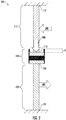
FIG. 1 is a perspective view of thermally driven elastocaloric system with a first SMA member, a second SMA member, and a connection mechanism. -
FIG. 2 is a perspective view of a thermally driven elastocaloric system, as shown inFIG. 1 , with heat being transferred to the first SMA member. -
FIG. 3 is a perspective view of a thermally driven elastocaloric system, as shown inFIG. 1 , with heat being transferred to the second SMA member. -
FIG. 4 is a perspective view of a thermally driven elastocaloric system, as shown inFIG. 1 , with heat being transferred from the second SMA member. -
FIG. 5 is a perspective view of a thermally driven elastocaloric system, as shown inFIG. 1 , with heat being transferred from the first SMA member. -
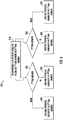
FIG. 6 is a flow diagram illustrating a method for generating at least one of a heating potential and a cooling potential. - A thermally driven elastocaloric system and a method for generating at least one of a heating potential and a cooing potential are provided. The thermally driven elastocaloric system and the method both incorporate the transfer of a thermal energy to/from one shape memory alloy (SMA) member to generate mechanical force, which is applied to another shape memory alloy (SMA) member (e.g., using a connection mechanism) to cause the SMA member to either absorb or release thermal energy. Accordingly, the thermally driven elastocaloric system incorporates two separate SMA members (e.g., described herein as the first SMA member and the second SMA member). Both the first SMA member and the second SMA members respectfully include a proximal end and a distal end. A connection mechanism is configured between the distal end of the first SMA member and the distal end of the second SMA member. The connection mechanism is configured to transfer a force (e.g., either a compressive force or a tensile force) between the first SMA member and the second SMA member. The transfer of a compressive force to an SMA member generates a heating potential in the SMA member and the transfer of a tensile force to an SMA member generates a cooling potential in the SMA member. It is envisioned that the system and method described herein may be useful in any application, which has a waste heat source and/or relies on thermodynamic principles (e.g., heating, ventilation and/or air conditioning (HVAC) systems or refrigeration systems). It should be appreciated that the thermal potential generated in the second SMA member may vary based on the composition of each SMA member, as different SMA materials may have different transition temperatures and/or phase change temperatures.
- With reference now to the Figures, an exemplary thermally driven
elastocaloric system 100 is shown inFIG. 1 . The thermally drivenelastocaloric system 100 includes afirst SMA member 110, asecond SMA member 120, and aconnection mechanism 130. Thefirst SMA member 110 has aproximal end 111 and adistal end 112. Thesecond SMA member 120 has aproximal end 121 and adistal end 122. Theconnection mechanism 130 is configured between thedistal end 112 of thefirst SMA member 110 and thedistal end 122 of thesecond SMA member 120. Theconnection mechanism 130 is configured to transfer aforce first SMA member 110 and thesecond SMA member 120. - It should be appreciated each
respective SMA member SMA member respective SMA member first SMA member 110 may be composed of different shape memory alloy than the element(s) making up thesecond SMA member 120. However, it is envisioned that the element(s) making up thefirst SMA member 110 may be composed of the same shape memory alloy as the element(s) making up thesecond SMA member 120. It is envisioned that each respective SMA member may have specific shapes or mechanisms to enhance heat transfer proprieties (e.g., fins or internal channels to facilitate fluid circulation). - At least a portion of the
first SMA member 110 and/or thesecond SMA member 120 may be made of nickel-titanium (NiTi, also known as "Nitinol"). In certain instances, at least oneSMA member SMA member SMA member SMA member connection mechanism 130; (ii) the composition of theother SMA member SMA member - It is envisioned that the
connection mechanism 130 may be any suitable structure capable of transferring a force (e.g., a compressive force or tensile force) from one SMA member (e.g., from the first SMA member 110) to another SMA member (e.g., to the second SMA member 120). The main function of the connection mechanism is to transfer force while limiting or eliminating heat transfer by conduction (e.g., the connection mechanism may be made of material that provides heat insulation and has a high mechanical rigidity). For example, theconnection mechanism 130 may be in the form of a piston or driveshaft. Thedistal end 112 of thefirst SMA member 110 and thedistal end 122 of thesecond SMA member 120 each may respectively be clamped or otherwise fixed to theconnection mechanism 130. However, it should be appreciated that thedistal end SMA member proximal end 111 of the first SMA member and/or theproximal end 121 of thesecond SMA member 120 each may respectively be fixed to or closely spaced from a rigid structure (e.g., a housing). It should be appreciated that eitherend first SMA member 110 and either end 121, 122 of the second SMA member may be configured in any way that allows aforce connection mechanism 130. - An exemplary embodiment of a thermally driven
elastocaloric system 100 withheat 200 being transferred to thefirst SMA member 110 and aforce 300 being transferred to thesecond SMA member 120 is shown inFIG. 2 . To transferheat 200 to the first SMA member 110 a working fluid (e.g., air, water, glycol, refrigerant, etc.) having a higher temperature than thefirst SMA member 110 may be passed over thefirst SMA member 110. Whenheat 200 is transferred to thefirst SMA member 110, thefirst SMA member 110 changes shape (e.g., length). This change may be viewed in terms of a deflection (d), as illustrated inFIG. 2 . A typical deflection for a shape memory alloy may be around 4%. For example, if thefirst SMA member 110 is 1 meter in length, thefirst SMA member 110 may be expected to "grow" by approximately 4 cm whenheat 200 is transferred to thefirst SMA member 110. This change is length is translated through theconnection mechanism 130 generating acompressive force 300 on thesecond SMA member 120. Thiscompressive force 300 generates aheating potential 400 in the second SMA member 120 (e.g., as an exothermic reaction). Thisheating potential 400 allows thesecond SMA member 120 to be able to release heat (e.g., to a working fluid, such as a refrigerant or air). - This process may be similarly completed by transferring
heat 200 to thesecond SMA member 120. An exemplary embodiment of a thermally drivenelastocaloric system 100 withheat 200 being transferred to thesecond SMA member 120 and aforce 300 being transferred to thefirst SMA member 110 is shown inFIG. 3 . To transferheat 200 to the second SMA member 120 a working fluid (e.g., air, water, glycol, refrigerant, etc.) having a higher temperature than thesecond SMA member 120 may be passed over thesecond SMA member 120. Whenheat 200 is transferred to thesecond SMA member 120, thesecond SMA member 120 changes shape (e.g., length). This change may be viewed in terms of a deflection (d), as illustrated inFIG. 3 . As mentioned above, this deflection may be around 4%. For example, if thesecond SMA member 120 is 1 meter in length, thesecond SMA member 120 may be expected to "grow" by approximately 4 cm whenheat 200 is transferred to thesecond SMA member 120. This change in length is translated through theconnection mechanism 130 generating acompressive force 300 on thefirst SMA member 110. Thiscompressive force 300 generates aheating potential 400 in the first SMA member 110 (e.g., as an exothermic reaction). Thisheating potential 400 allows thefirst SMA member 110 to be able to release heat (e.g., to a working fluid, such as a refrigerant or air). - Similarly,
heat 200 may be transferred fromsecond SMA member 120. An exemplary embodiment of a thermally drivenelastocaloric system 100 withheat 200 being transferred from thesecond SMA member 120 and aforce 600 being transferred to thefirst SMA member 110 is shown inFIG. 4 . To transferheat 200 from the second SMA member 120 a working fluid (e.g., air, water, glycol, refrigerant, etc.) having a lower temperature than thesecond SMA member 120 may be passed over thesecond SMA member 120. Whenheat 200 is transferred from thesecond SMA member 120, thesecond SMA member 120 changes shape (e.g., length). This change may be viewed in terms of a deflection (d), as illustrated inFIG. 4 . As mentioned above, this deflection may be around 4%. For example, if thesecond SMA member 120 is 1 meter in length, thesecond SMA member 120 may be expected to "shrink" by approximately 4 cm whenheat 200 is transferred from thesecond SMA member 120. This change is length is translated through theconnection mechanism 130 generating atensile force 600 on thefirst SMA member 110. Thistensile force 300 generates a cooling potential 500 in the first SMA member 110 (e.g., as an endothermic reaction). This cooling potential 500 allows thefirst SMA member 110 to be able to absorb heat (e.g., from a working fluid, such as a refrigerant or air). - This process may be similarly completed by transferring
heat 200 from thefirst SMA member 110. An exemplary embodiment of a thermally drivenelastocaloric system 100 withheat 200 being transferred from thefirst SMA member 110 and aforce 600 being transferred to thesecond SMA member 120 is shown inFIG. 5 . To transferheat 200 from the first SMA member 110 a working fluid (e.g., air, water, glycol, refrigerant, etc.) having a lower temperature than thefirst SMA member 110 may be passed over thefirst SMA member 110. Whenheat 200 is transferred from thefirst SMA member 110, thefirst SMA member 110 changes shape (e.g., length). This change may be viewed in terms of a deflection (d), as illustrated inFIG. 5 . As mentioned above, this deflection may be around 4%. For example, if thefirst SMA member 110 is 1 meter in length, thefirst SMA member 110 may be expected to "shrink" by approximately 4 cm whenheat 200 is transferred from thefirst SMA member 110. This change in length is translated through theconnection mechanism 130 generating atensile force 600 on thesecond SMA member 120. Thistensile force 300 generates a cooling potential 500 in the second SMA member 120 (e.g., as an endothermic reaction). This cooling potential 500 allows thesecond SMA member 120 to be able to absorb heat (e.g., from a working fluid, such as a refrigerant or air). - The configuration of the thermally driven
elastocaloric system 100 makes is possible to generate a thermal potential (e.g., a heating potential or a cooling potential) without reliance on electrical power or combustible fuel. As mentioned above, this method of producing a thermal potential may be particularly useful in any application, which has a waste heat source and/or relies on thermodynamic principles (e.g., heating, ventilation and/or air conditioning (HVAC) systems). This method of generating at least one of a heating potential and a cooling potential is shown inFIG. 6 . - This
method 800 may be completed, for example, using the exemplary thermally drivenelastocaloric system 100 shown inFIGs. 1-5 . As described above, themethod 800 may provide for the transferring of heat between (e.g., to or from) a working fluid and at least one of afirst SMA member 110 and asecond SMA member 120, as illustrated bystep 810 inFIG. 6 . Aconnection mechanism 130 may be configured between thefirst SMA member 110 and thesecond SMA member 120. Themethod 800 provides for the transferring of a force (e.g., acompressive force 300 or a tensile force 600) between theconnection mechanism 130 and at least one of thefirst SMA member 110 and thesecond SMA member 120. The transfer of acompressive force 300 may generate aheating potential 400. The transfer of atensile force 600 may generate a coolingpotential 500. -
FIG. 6 is provided to illustrate the generation ofthermal potentials heat 200 is transferred. Step 820 illustrates the transfer ofheat 200 either to or from the first SMA member 110 (e.g., by a working fluid). If transferred from the first SMA member 110 a cooling potential 500 is generated in the second SMA member 120 (shown by step 821). If transferred to the first SMA member 110 aheating potential 400 is generated in the second SMA member 120 (shown by step 822). Step 830 illustrates the transfer ofheat 200 either to or from the second SMA member 120 (e.g., by a working fluid). If transferred to the second SMA member 120 aheating potential 400 is generated in thefirst SMA member 110. If transferred from the second SMA member 120 a cooling potential 500 is generated in thefirst SMA member 110. - The use of the terms "a" and "and" and "the" and similar referents, in the context of describing the invention, are to be construed to cover both the singular and the plural, unless otherwise indicated herein or cleared contradicted by context. The use of any and all example, or exemplary language (e.g., "such as", "e.g.", "for example", etc.) provided herein is intended merely to better illuminate the invention and does not pose a limitation on the scope of the invention unless otherwise claimed. No language in the specification should be construed as indicating any non-claimed elements as essential to the practice of the invention.
- While the present disclosure has been described with reference to an exemplary embodiment or embodiments, it will be understood by those skilled in the art that various changes may be made and equivalents may be substituted for elements thereof without departing from the scope of the present disclosure. In addition, many modifications may be made to adapt a particular situation or material to the teachings of the present disclosure without departing from the essential scope thereof. Therefore, it is intended that the present disclosure not be limited to the particular embodiment disclosed as the best mode contemplated for carrying out this present disclosure, but that the present disclosure will include all embodiments falling within the scope of the claims.
Claims (15)
- A thermally driven elastocaloric system comprising:a first shape memory alloy (SMA) member (110) comprising a proximal end (111) and a distal end (112);a second shape memory alloy (SMA) member (120) comprising a proximal end (121) and a distal end (122); anda connection mechanism (130) configured between the distal end (112) of the first SMA member (110) and the distal end (122) of the second SMA member (120), the connection mechanism (130) configured to transfer a force (300, 600) between the first SMA member (110) and the second SMA member (120).
- The thermally driven elastocaloric system of claim 1, further comprising a working fluid for transferring a heat (200) between the working fluid and at least one of the first SMA member (110) and the second SMA member (120).
- The thermally driven elastocaloric system of claim 2, wherein the working fluid is configured to transfer heat (200) to the first SMA member (110).
- The thermally driven elastocaloric system of claim 3, wherein the connection mechanism (130) transfers a compressive force (300) to the second SMA member (120) when heat (200) is transferred from the working fluid to the first SMA member (110).
- The thermally driven elastocaloric system of claim 4, wherein the compressive force (300) transferred by the connection mechanism (130) to the second SMA member (120) generates a heating potential (400) in the second SMA member (120).
- The thermally driven elastocaloric system of any of claims 2 to 5, wherein the working fluid is configured to transfer heat (200) to the second SMA member (120).
- The thermally driven elastocaloric system of claim 6, wherein the connection mechanism (130) transfers a compressive force (300) to the first SMA member (110) when heat (200) is transferred from the working fluid to the second SMA member (120); preferably wherein the compressive force (300) transferred by the connection mechanism (130) to the first SMA member (110) generates a heating potential (400) in the first SMA member (110).
- The thermally driven elastocaloric system of any of claims 2 to 7, wherein the working fluid is configured to transfer heat (200) from the first SMA member (110).
- The thermally driven elastocaloric system of claim 8, wherein the connection mechanism (130) transfers a tensile force (600) to the second SMA member (120) when heat (200) is transferred from the first SMA member (110) to the working fluid; preferably wherein the tensile force (600) transferred by the connection mechanism (130) to the second SMA member (120) generates a cooling potential (500) in the second SMA member (120).
- The thermally driven elastocaloric system of any of claims 2 to 9, wherein the working fluid is configured to transfer heat (200) from the second SMA member (120).
- The thermally driven elastocaloric system of claim 10, wherein the connection mechanism (130) transfers a tensile force (600) to the first SMA member (110) when heat (200) is transferred from the second SMA member (120) to the working fluid; preferably wherein the tensile force (600) transferred by the connection mechanism (130) to the first SMA member (110) generates a cooling potential (500) in the first SMA member (110).
- A method for generating at least one of a heating potential and a cooling potential, the method comprising:transferring a heat (200) between a working fluid and at least one of a first SMA member (110) and a second SMA member (120), a connection mechanism (130) configured between the first SMA member (110) and the second SMA member (120); andtransferring a force (300, 600) between the connection mechanism (130) and at least one of the first SMA member (110) and the second SMA member (120), the force comprising at least one of: a compressive force (300) and a tensile force (600).
- The method of claim 12, wherein the transfer of the compressive force (300) generates a heating potential (400) and the transfer of a tensile force (600) generates a cooling potential (500).
- The method of claim 12 or 13, wherein the transfer of heat (200) from the working fluid to the first SMA member (110) generates the transfer of compressive force (300) from the connection mechanism (130) to the second SMA member (120); preferably wherein the compressive force (300) transferred by the connection mechanism (130) to the second SMA member (120) generates a heating potential (400) in the second SMA member (120).
- The method of claim 12, 13 or 14, wherein the transfer of heat (200) from the first SMA member (110) to the working fluid generates the transfer of tensile force (600) from the connection mechanism (130) to the second SMA member (120); preferably wherein the tensile force (600) transferred by the connection mechanism (130) to the second SMA member (120) generates a cooling potential (500) in the second SMA member (120).
Applications Claiming Priority (1)
| Application Number | Priority Date | Filing Date | Title |
|---|---|---|---|
| US202063010823P | 2020-04-16 | 2020-04-16 |
Publications (1)
| Publication Number | Publication Date |
|---|---|
| EP3896282A1 true EP3896282A1 (en) | 2021-10-20 |
Family
ID=75252283
Family Applications (1)
| Application Number | Title | Priority Date | Filing Date |
|---|---|---|---|
| EP21164985.0A Pending EP3896282A1 (en) | 2020-04-16 | 2021-03-25 | Thermally driven elastocaloric system |
Country Status (3)
| Country | Link |
|---|---|
| US (1) | US11655804B2 (en) |
| EP (1) | EP3896282A1 (en) |
| CN (1) | CN113530775A (en) |
Cited By (1)
| Publication number | Priority date | Publication date | Assignee | Title |
|---|---|---|---|---|
| CN114992903A (en) * | 2022-05-26 | 2022-09-02 | 西安交通大学 | Two-stage cascade type elastic thermal refrigerator and refrigerating method thereof |
Families Citing this family (2)
| Publication number | Priority date | Publication date | Assignee | Title |
|---|---|---|---|---|
| CN115900144B (en) * | 2022-12-27 | 2026-02-06 | 西安交通大学 | Active heat regenerator for elastic heating refrigeration and heat pump system and connection method |
| CN118423889B (en) * | 2024-07-03 | 2024-09-03 | 哈尔滨工业大学(深圳)(哈尔滨工业大学深圳科技创新研究院) | Continuous torsion card refrigerator based on shape memory material card flicking effect |
Citations (3)
| Publication number | Priority date | Publication date | Assignee | Title |
|---|---|---|---|---|
| GB2533357A (en) * | 2014-12-17 | 2016-06-22 | Exergyn Ltd | Heat transfer in an energy recovery device |
| DE102016100596A1 (en) * | 2015-12-11 | 2017-06-14 | Fraunhofer-Gesellschaft zur Förderung der angewandten Forschung e.V. | Method and device for operating cycle-based systems |
| US20200088449A1 (en) * | 2018-09-17 | 2020-03-19 | Department of the Army, U.S. Army CCDC Army Research Laboratory | Continuous bending-mode elastocaloric cooling/heating flow loop |
Family Cites Families (25)
| Publication number | Priority date | Publication date | Assignee | Title |
|---|---|---|---|---|
| US5821664A (en) * | 1996-03-28 | 1998-10-13 | Shahinpoor; Moshen | Fibrous parallel spring-loaded shape memory alloy rebotic linear |
| ES2188331B1 (en) * | 2000-09-20 | 2004-06-16 | Sener, Ingenieria Y Sistemas, S.A. | MECHANISM OF LOOP AND RELEASE OF EQUIPMENT WITH REMOTE ACTION. |
| US7655001B2 (en) * | 2001-03-23 | 2010-02-02 | Petrakis Dennis N | Temperature responsive systems |
| US7220051B2 (en) * | 2001-12-05 | 2007-05-22 | Mohsen Shahinpoor | Shape memory alloy temperature sensor and switch |
| US7105014B2 (en) * | 2002-11-22 | 2006-09-12 | Medtronic Vascular, Inc. | Stent delivery and retention apparatus |
| EP2212665A1 (en) * | 2007-10-31 | 2010-08-04 | ABB Technology AG | Temperature monitoring device for high-voltage and medium-voltage components |
| US8631652B2 (en) | 2009-11-20 | 2014-01-21 | GM Global Technology Operations LLC | Heat engine system |
| US10119059B2 (en) | 2011-04-11 | 2018-11-06 | Jun Cui | Thermoelastic cooling |
| FR2983572B1 (en) | 2011-12-02 | 2014-01-24 | Commissariat Energie Atomique | DEVICE FOR GENERATING A SECOND TEMPERATURE VARIATION FROM A FIRST TEMPERATURE VARIATION |
| US10107529B2 (en) | 2013-02-06 | 2018-10-23 | Daikin Industries, Ltd. | Cooling/heating module and air conditioning device |
| JP2015068619A (en) | 2013-09-30 | 2015-04-13 | ダイキン工業株式会社 | Cooling and heating module and air conditioner |
| GB2533336A (en) | 2014-12-16 | 2016-06-22 | Exergyn Ltd | Optimised diametric contraction of a SMA element for use in an energy recovery device |
| US10323865B2 (en) | 2015-11-12 | 2019-06-18 | Jun Cui | Compact thermoelastic cooling system |
| DE102015121657A1 (en) | 2015-12-11 | 2017-06-14 | Fraunhofer-Gesellschaft zur Förderung der angewandten Forschung e.V. | Method and device for operating cycle-based systems |
| CN106052190B (en) | 2016-06-01 | 2019-01-08 | 西安交通大学 | An active regenerative elastic thermal refrigeration system |
| DE102016118776A1 (en) | 2016-10-04 | 2018-04-05 | Universität des Saarlandes | Energy converter with thermoelastic arrangement and energy converter system |
| SI25312A (en) | 2016-11-16 | 2018-05-31 | Univerza V Ljubljani | A hybrid heat station |
| DE102018200376A1 (en) | 2018-01-11 | 2019-07-11 | Robert Bosch Gmbh | Device for heat exchange |
| DE102018200372A1 (en) | 2018-01-11 | 2019-07-11 | Robert Bosch Gmbh | Structure of elastocaloric materials |
| DE102018200792A1 (en) | 2018-01-18 | 2019-07-18 | Robert Bosch Gmbh | System for heat exchange |
| GB201801534D0 (en) * | 2018-01-30 | 2018-03-14 | Exergyn Ltd | A heat pump utilising the shape memory effect |
| DE102018202953A1 (en) | 2018-02-28 | 2019-08-29 | Robert Bosch Gmbh | Elastokaloric element with three layers of material |
| DE102018207577A1 (en) | 2018-05-16 | 2019-11-21 | Robert Bosch Gmbh | Device for heat exchange |
| DE102018213505A1 (en) | 2018-08-10 | 2020-02-13 | Robert Bosch Gmbh | Device for heat exchange with an elastocaloric element |
| DE102018213497A1 (en) | 2018-08-10 | 2020-02-13 | Robert Bosch Gmbh | Means for heat exchange with an elastocaloric element which encloses a fluid line |
-
2021
- 2021-03-25 EP EP21164985.0A patent/EP3896282A1/en active Pending
- 2021-04-08 US US17/301,571 patent/US11655804B2/en active Active
- 2021-04-16 CN CN202110410819.5A patent/CN113530775A/en active Pending
Patent Citations (3)
| Publication number | Priority date | Publication date | Assignee | Title |
|---|---|---|---|---|
| GB2533357A (en) * | 2014-12-17 | 2016-06-22 | Exergyn Ltd | Heat transfer in an energy recovery device |
| DE102016100596A1 (en) * | 2015-12-11 | 2017-06-14 | Fraunhofer-Gesellschaft zur Förderung der angewandten Forschung e.V. | Method and device for operating cycle-based systems |
| US20200088449A1 (en) * | 2018-09-17 | 2020-03-19 | Department of the Army, U.S. Army CCDC Army Research Laboratory | Continuous bending-mode elastocaloric cooling/heating flow loop |
Cited By (2)
| Publication number | Priority date | Publication date | Assignee | Title |
|---|---|---|---|---|
| CN114992903A (en) * | 2022-05-26 | 2022-09-02 | 西安交通大学 | Two-stage cascade type elastic thermal refrigerator and refrigerating method thereof |
| CN114992903B (en) * | 2022-05-26 | 2023-08-18 | 西安交通大学 | Double-stage overlapping type elastic heating refrigerator and refrigerating method thereof |
Also Published As
| Publication number | Publication date |
|---|---|
| CN113530775A (en) | 2021-10-22 |
| US11655804B2 (en) | 2023-05-23 |
| US20210324839A1 (en) | 2021-10-21 |
Similar Documents
| Publication | Publication Date | Title |
|---|---|---|
| US11655804B2 (en) | Thermally driven elastocaloric system | |
| US10323865B2 (en) | Compact thermoelastic cooling system | |
| US11656008B2 (en) | Heat pump utilising the shape memory effect | |
| CN102108955B (en) | Cooling system | |
| US8631652B2 (en) | Heat engine system | |
| US20220357083A1 (en) | Elastocaloric heat recovery in a heat pump / refrigeration system using a pump mechanism | |
| US12072125B2 (en) | System and method for maximising heat output and temperature delta in a SMA heat pump/refrigeration system | |
| WO2016097214A1 (en) | Heat transfer in an energy recovery device | |
| Kirsch et al. | Continuous operating elastocaloric heating and cooling device: air flow investigation and experimental parameter study | |
| EP2562505A1 (en) | Integrated pressure compensating heat exchanger and method | |
| Sharar et al. | First demonstration of a bending-mode elastocaloric cooling ‘loop’ | |
| Jeong et al. | Modeling and analysis of SMA actuator embedded in stretchable coolant vascular pursuing artificial muscles | |
| US4922718A (en) | Thermal energy scavenger | |
| US12378951B2 (en) | Gas separated cycling of SMA/NTE bundles in a fluid environment for power production cycle or heat pump cycles | |
| Welsch et al. | Elastocaloric cooling: system design, simulation, and realization | |
| Kozyrskyi et al. | Experimental Studies of Elements from the Functional Intermetallic Cu-Al-Mn forConstruction of a Heat Engine and Power Plant | |
| TERMI et al. | Stabilized actuation of a novel niti shape-memory-alloy-actuated flexible structure under thermal loading | |
| DE102012202398A1 (en) | Energy recovery system | |
| Johnson et al. | State-of-the-art of shape memory actuators | |
| Cho et al. | Fabrication and output power characteristics of heat-engines using tape-shaped SMA element | |
| DE102010051803B4 (en) | Cooling system for converting thermal energy into mechanical energy | |
| EP3317536B1 (en) | Sma bundle wire optimisation in an energy recovery device | |
| Jo et al. | Design and performance evaluation of extension-type actuators with a displacement amplification mechanism based on chevron beam | |
| US20260104186A1 (en) | Elastocaloric system and method of operation | |
| US20200080753A1 (en) | Green Cycle Heat Pump Engine |
Legal Events
| Date | Code | Title | Description |
|---|---|---|---|
| PUAI | Public reference made under article 153(3) epc to a published international application that has entered the european phase |
Free format text: ORIGINAL CODE: 0009012 |
|
| STAA | Information on the status of an ep patent application or granted ep patent |
Free format text: STATUS: THE APPLICATION HAS BEEN PUBLISHED |
|
| AK | Designated contracting states |
Kind code of ref document: A1 Designated state(s): AL AT BE BG CH CY CZ DE DK EE ES FI FR GB GR HR HU IE IS IT LI LT LU LV MC MK MT NL NO PL PT RO RS SE SI SK SM TR |
|
| B565 | Issuance of search results under rule 164(2) epc |
Effective date: 20210816 |
|
| STAA | Information on the status of an ep patent application or granted ep patent |
Free format text: STATUS: REQUEST FOR EXAMINATION WAS MADE |
|
| 17P | Request for examination filed |
Effective date: 20220413 |
|
| RBV | Designated contracting states (corrected) |
Designated state(s): AL AT BE BG CH CY CZ DE DK EE ES FI FR GB GR HR HU IE IS IT LI LT LU LV MC MK MT NL NO PL PT RO RS SE SI SK SM TR |
|
| P01 | Opt-out of the competence of the unified patent court (upc) registered |
Effective date: 20230527 |
|
| STAA | Information on the status of an ep patent application or granted ep patent |
Free format text: STATUS: EXAMINATION IS IN PROGRESS |
|
| 17Q | First examination report despatched |
Effective date: 20240102 |
|
| GRAP | Despatch of communication of intention to grant a patent |
Free format text: ORIGINAL CODE: EPIDOSNIGR1 |
|
| STAA | Information on the status of an ep patent application or granted ep patent |
Free format text: STATUS: GRANT OF PATENT IS INTENDED |
|
| INTG | Intention to grant announced |
Effective date: 20251002 |