EP3896275B1 - Vehicle with engine intake passage structure - Google Patents
Vehicle with engine intake passage structure Download PDFInfo
- Publication number
- EP3896275B1 EP3896275B1 EP21163475.3A EP21163475A EP3896275B1 EP 3896275 B1 EP3896275 B1 EP 3896275B1 EP 21163475 A EP21163475 A EP 21163475A EP 3896275 B1 EP3896275 B1 EP 3896275B1
- Authority
- EP
- European Patent Office
- Prior art keywords
- vehicle
- projecting portion
- intake
- surge tank
- engine
- Prior art date
- Legal status (The legal status is an assumption and is not a legal conclusion. Google has not performed a legal analysis and makes no representation as to the accuracy of the status listed.)
- Active
Links
Images


Classifications
-
- F—MECHANICAL ENGINEERING; LIGHTING; HEATING; WEAPONS; BLASTING
- F02—COMBUSTION ENGINES; HOT-GAS OR COMBUSTION-PRODUCT ENGINE PLANTS
- F02M—SUPPLYING COMBUSTION ENGINES IN GENERAL WITH COMBUSTIBLE MIXTURES OR CONSTITUENTS THEREOF
- F02M35/00—Combustion-air cleaners, air intakes, intake silencers, or induction systems specially adapted for, or arranged on, internal-combustion engines
- F02M35/10—Air intakes; Induction systems
- F02M35/10006—Air intakes; Induction systems characterised by the position of elements of the air intake system in direction of the air intake flow, i.e. between ambient air inlet and supply to the combustion chamber
- F02M35/10026—Plenum chambers
- F02M35/10052—Plenum chambers special shapes or arrangements of plenum chambers; Constructional details
-
- B—PERFORMING OPERATIONS; TRANSPORTING
- B60—VEHICLES IN GENERAL
- B60K—ARRANGEMENT OR MOUNTING OF PROPULSION UNITS OR OF TRANSMISSIONS IN VEHICLES; ARRANGEMENT OR MOUNTING OF PLURAL DIVERSE PRIME-MOVERS IN VEHICLES; AUXILIARY DRIVES FOR VEHICLES; INSTRUMENTATION OR DASHBOARDS FOR VEHICLES; ARRANGEMENTS IN CONNECTION WITH COOLING, AIR INTAKE, GAS EXHAUST OR FUEL SUPPLY OF PROPULSION UNITS IN VEHICLES
- B60K13/00—Arrangement in connection with combustion air intake or gas exhaust of propulsion units
- B60K13/02—Arrangement in connection with combustion air intake or gas exhaust of propulsion units concerning intake
-
- B—PERFORMING OPERATIONS; TRANSPORTING
- B60—VEHICLES IN GENERAL
- B60K—ARRANGEMENT OR MOUNTING OF PROPULSION UNITS OR OF TRANSMISSIONS IN VEHICLES; ARRANGEMENT OR MOUNTING OF PLURAL DIVERSE PRIME-MOVERS IN VEHICLES; AUXILIARY DRIVES FOR VEHICLES; INSTRUMENTATION OR DASHBOARDS FOR VEHICLES; ARRANGEMENTS IN CONNECTION WITH COOLING, AIR INTAKE, GAS EXHAUST OR FUEL SUPPLY OF PROPULSION UNITS IN VEHICLES
- B60K17/00—Arrangement or mounting of transmissions in vehicles
- B60K17/22—Arrangement or mounting of transmissions in vehicles characterised by arrangement, location, or type of main drive shafting, e.g. cardan shaft
-
- B—PERFORMING OPERATIONS; TRANSPORTING
- B60—VEHICLES IN GENERAL
- B60K—ARRANGEMENT OR MOUNTING OF PROPULSION UNITS OR OF TRANSMISSIONS IN VEHICLES; ARRANGEMENT OR MOUNTING OF PLURAL DIVERSE PRIME-MOVERS IN VEHICLES; AUXILIARY DRIVES FOR VEHICLES; INSTRUMENTATION OR DASHBOARDS FOR VEHICLES; ARRANGEMENTS IN CONNECTION WITH COOLING, AIR INTAKE, GAS EXHAUST OR FUEL SUPPLY OF PROPULSION UNITS IN VEHICLES
- B60K5/00—Arrangement or mounting of internal-combustion or jet-propulsion units
- B60K5/02—Arrangement or mounting of internal-combustion or jet-propulsion units with the engine main axis, e.g. crankshaft axis, substantially in or parallel to the longitudinal centre line of the vehicle
-
- F—MECHANICAL ENGINEERING; LIGHTING; HEATING; WEAPONS; BLASTING
- F02—COMBUSTION ENGINES; HOT-GAS OR COMBUSTION-PRODUCT ENGINE PLANTS
- F02M—SUPPLYING COMBUSTION ENGINES IN GENERAL WITH COMBUSTIBLE MIXTURES OR CONSTITUENTS THEREOF
- F02M35/00—Combustion-air cleaners, air intakes, intake silencers, or induction systems specially adapted for, or arranged on, internal-combustion engines
- F02M35/10—Air intakes; Induction systems
- F02M35/10006—Air intakes; Induction systems characterised by the position of elements of the air intake system in direction of the air intake flow, i.e. between ambient air inlet and supply to the combustion chamber
- F02M35/10078—Connections of intake systems to the engine
-
- F—MECHANICAL ENGINEERING; LIGHTING; HEATING; WEAPONS; BLASTING
- F02—COMBUSTION ENGINES; HOT-GAS OR COMBUSTION-PRODUCT ENGINE PLANTS
- F02M—SUPPLYING COMBUSTION ENGINES IN GENERAL WITH COMBUSTIBLE MIXTURES OR CONSTITUENTS THEREOF
- F02M35/00—Combustion-air cleaners, air intakes, intake silencers, or induction systems specially adapted for, or arranged on, internal-combustion engines
- F02M35/10—Air intakes; Induction systems
- F02M35/10242—Devices or means connected to or integrated into air intakes; Air intakes combined with other engine or vehicle parts
- F02M35/10262—Flow guides, obstructions, deflectors or the like
-
- F—MECHANICAL ENGINEERING; LIGHTING; HEATING; WEAPONS; BLASTING
- F02—COMBUSTION ENGINES; HOT-GAS OR COMBUSTION-PRODUCT ENGINE PLANTS
- F02M—SUPPLYING COMBUSTION ENGINES IN GENERAL WITH COMBUSTIBLE MIXTURES OR CONSTITUENTS THEREOF
- F02M35/00—Combustion-air cleaners, air intakes, intake silencers, or induction systems specially adapted for, or arranged on, internal-combustion engines
- F02M35/10—Air intakes; Induction systems
- F02M35/104—Intake manifolds
- F02M35/1045—Intake manifolds characterised by the charge distribution between the cylinders/combustion chambers or its homogenisation
-
- F—MECHANICAL ENGINEERING; LIGHTING; HEATING; WEAPONS; BLASTING
- F02—COMBUSTION ENGINES; HOT-GAS OR COMBUSTION-PRODUCT ENGINE PLANTS
- F02M—SUPPLYING COMBUSTION ENGINES IN GENERAL WITH COMBUSTIBLE MIXTURES OR CONSTITUENTS THEREOF
- F02M35/00—Combustion-air cleaners, air intakes, intake silencers, or induction systems specially adapted for, or arranged on, internal-combustion engines
- F02M35/10—Air intakes; Induction systems
- F02M35/104—Intake manifolds
- F02M35/112—Intake manifolds for engines with cylinders all in one line
-
- Y—GENERAL TAGGING OF NEW TECHNOLOGICAL DEVELOPMENTS; GENERAL TAGGING OF CROSS-SECTIONAL TECHNOLOGIES SPANNING OVER SEVERAL SECTIONS OF THE IPC; TECHNICAL SUBJECTS COVERED BY FORMER USPC CROSS-REFERENCE ART COLLECTIONS [XRACs] AND DIGESTS
- Y02—TECHNOLOGIES OR APPLICATIONS FOR MITIGATION OR ADAPTATION AGAINST CLIMATE CHANGE
- Y02T—CLIMATE CHANGE MITIGATION TECHNOLOGIES RELATED TO TRANSPORTATION
- Y02T10/00—Road transport of goods or passengers
- Y02T10/10—Internal combustion engine [ICE] based vehicles
- Y02T10/12—Improving ICE efficiencies
Definitions
- the present disclosure relates to an intake passage structure of an in-vehicle engine.
- JP-A-2020-2796 discloses the intake device of a multi-cylinder engine equipped with a surge tank directly connected to the entrance portion of an intake port. Specifically, the ceiling surface of the inner peripheral surface of this surge tank extends in the cylinder row direction, that is, the engine output shaft direction.
- JP-A-2008-285999 discloses an intake manifold equipped with a surge tank connected to the intake port via the intake pipe.
- the intake manifold disclosed in JP-A-2008-285999 includes a partition plate that divides the lower space formed below the opening end of the surge tank into the left and right portions. According to the JP-A-2008-285999 described above, the intake air toward the lower space is blocked from flowing into the lower space by the partition plate.
- EP 3 043 061 A1 discloses an intake system for an internal combustion engine.
- the intake system includes plural intake pipes being configured to be connected to cylinders of a main body of the internal combustion engine, respectively, an external gas distribution portion distributing a single type of an external gas to each of the plural intake pipes, a main body of the intake system including the plural intake pipes and the external gas distribution portion, and an external gas introduction passage being integrally formed with the main body of the intake system, the external gas introduction passage being configured to connect the main body of the internal combustion engine to the external gas distribution portion of the main body of the intake system, the external gas introduction passage serving as a single passage being configured to introduce the external gas from the main body of the internal combustion engine to the external gas distribution portion.
- JP 2011 185 147 A discloses an intake manifold being provided with a communicating pipe that communicates a lower portion of the surge tank with an airflow separation section (intake branch side) of a bent section while bypassing the intake downstream side of the surge tank.
- a differential pressure is produced between both ends of the communicating pipe by airflow separation or the like caused by the flow of intake, and a fluid suction force from the surge tank side to the intake branch side is created inside the communicating pipe. In this way, water or oil in the lower portion of the surge tank can be sucked up into the intake branch via the communicating pipe and be sucked into the engine.
- An air intake apparatus is known from EP 3 480 449 A1 .
- the cylinder row direction is also inclined downward.
- the ceiling surface of the surge tank described in the patent documents 1 and 2 and the like is also inclined downward along the engine output shaft and eventually the cylinder row direction.
- the inventors of the present application and the like have found new problems specific to low temperature environments such as winter and cold regions as a result of clarifying the concerns about the surge tank in which the ceiling surface is inclined downward.
- icicles are formed so as to extend from the ceiling surface of the surge tank because moisture in the air is frozen during parking.
- the icicles are melted after the engine is started, but the water produced by the melting flows along the ceiling surface inclined downward as described above and may be sucked unevenly into a specific cylinder through the intake port located in the lowermost portion. Suction of water into a specific cylinder can lead to unfavorable events such as water hammer.
- the technology disclosed herein addresses the problem described above with an object of causing the water produced by the melting of the icicles to be evenly sucked into the individual cylinders when the ceiling surface of the surge tank is inclined with respect to the engine output shaft.
- a first aspect of the present disclosure relates to a vehicle comprising an in-vehicle engine that has a plurality of cylinders and an engine output shaft disposed in a vehicle front and rear direction, the in-vehicle engine comprising an intake passage structure.
- the intake passage structure of an in-vehicle engine including a surge tank attached to an entrance portion of an intake port formed in a cylinder head of the in-vehicle engine, a ceiling surface of an inner peripheral surface of the surge tank being inclined downward along the engine output shaft, a first projecting portion extending in an intake and exhaust direction of the in-vehicle engine and projecting toward a bottom surface of the inner peripheral surface of the surge tank being formed on the ceiling surface, in which the in-vehicle engine is mounted on a vehicle in a state in which the engine output shaft is inclined downward toward one side in the vehicle front and rear direction.
- extending in the intake and exhaust direction of the in-vehicle engine includes “extending in a direction slightly inclined with respect to the intake and exhaust direction” in addition to “extending parallel to the intake and exhaust direction”.
- the angle formed by the extension direction of the first projecting portion and the intake and exhaust direction is smaller than the angle formed by the extension direction and the engine output shaft.
- the intake and exhaust direction preferably extends at an angle of 90° with respect to the extension direction of the engine output shaft.
- the angle formed by the extension direction of the first projecting portion and the extension direction of the engine output shaft is preferably bigger than 45°.
- the flow of water on the ceiling surface in the engine output shaft direction (cylinder row direction) can be blocked.
- the suction of water to a specific cylinder specifically, the cylinder located in the lowermost position
- the water produced by the melting of icicles can be sucked into the individual cylinders evenly.
- the ceiling surface may be disposed at a position higher in a vehicle height direction than an upper surface of an inner peripheral surface in the entrance portion of the intake port.
- the flow of water blocked by the first projecting portion can be smoothly guided to the cylinder close to the first projecting portion. This can achieve both the smooth suction into the individual cylinders and the suppression of suction into a specific cylinder.
- a projection amount of the first projecting portion may increase as the first projecting portion approaches the entrance portion of the intake port in the intake and exhaust direction.
- the projection amount of the first projecting portion is desirably made as large as possible to block the flow of water more reliably.
- the projection amount of the first projecting portion is excessively large, the circulation of intake air in the surge tank is obstructed and the distribution performance of intake air, which is the original function of the surge tank 8, may be hindered.
- the projection amount of an inner projecting portion of the first projecting portion may gradually increase towards the entrance portion of the intake port.
- a lower edge portion of the inner projecting portion extends to the same height as the bottom surface of the upstream end portion of the branch pipe. In an embodiment of the present invention, a lower edge portion of the inner projecting portion extends substantially linearly while being inclined with respect to the intake and exhaust direction.
- a dimension of the first projecting portion in an engine output shaft direction may be larger as the first projecting portion approaches the entrance portion of the intake port in the intake and exhaust direction.
- the dimension of the first projecting portion in the engine output shaft direction is desirably made as large as possible to block the flow of water more reliably.
- the dimension of the first projecting portion is excessively large, the volume of the surge tank is reduced and the distribution performance of intake air, which is the original function of the surge tank 8, may be hindered.
- the first projection portion comprises an inner projecting portion and an outer projecting portion, wherein the inner projecting portion has a larger thickness in the engine output shaft direction than the outer projecting portion.
- an inner projecting portion of the first projection portion may be formed by denting an outer surface of a first tank portion downward.
- an outer projecting portion of the first projection portion includes a rib-shaped projecting portion provided on the ceiling surface.
- the inner projection portion and the outer projecting portion are connected integrally with each other in the intake and exhaust direction.
- a second projecting portion that extends in the intake and exhaust direction and projects toward the ceiling surface may be formed on the bottom surface.
- the flow of water along the bottom surface can be blocked by the second projecting portion. This can suppress the suction of water into a specific cylinder.
- an introduction opening through which air is introduced into the surge tank may be provided in a middle portion in the engine output shaft direction of the bottom surface.
- the bottom surface is inclined downward toward the introduction opening.
- the second projecting portion extends toward the introduction opening.
- water can flow along the second projecting portion and the water can be guided to the introduction opening. This can discharge the water through the introduction opening.
- the engine comprises a plurality of intake ports and the surge tank may have a plurality of branch pipes connected to the entrance portions of the intake ports.
- the plurality of branch pipes is arranged so as to be inclined downward along the engine output shaft.
- the first projecting portion is disposed in a space between two adjacent branch pipes in the engine output shaft direction.
- the first projecting portions can block the water without interfering with the circulation of intake air through the branch pipes.
- each of at least two first projection portions may be disposed in the space between respective adjacent branch pipes.
- the second projection portion may be disposed in a space between adjacent branch pipes.
- each of at least two second projection portions is disposed in the space between respective adjacent branch pipes.
- At least part of the first projecting portion may be offset so as to be closer to the branch pipe located on a vehicle front side among the adjacent branch pipes.
- the flow of water along the ceiling surface can be reliably blocked at an earlier timing.
- an inner projecting portion of the first projection portion may disposed in the middle of adjacent branch pipes.
- an outer projecting portion of the first projection portion is disposed closer to a branch pipe located on the vehicle front side among the adjacent branch pipes.
- the surge tank may be such configured that water flowing along the ceiling surface is blocked in the engine output shaft direction by the at least one first projecting portion and is guided to a cylinder adjacent to the first projecting portions.
- the surge tank is such configured that flow of water along the bottom surface is blocked by the second projecting portions and is guided to an introduction opening provided in a bottom surface of the surge tank.
- the ceiling surface of the surge tank is inclined with respect to the engine output shaft, the water produced by the melting of icicles can be sucked into the individual cylinders evenly.
- Fig. 1 is a side view illustrating the structure of an engine E as an in-vehicle engine.
- Fig. 2 is a front view illustrating the structure of the engine E
- Fig. 3 is a perspective view illustrating the structure of the engine E
- Fig. 4 is a sectional view illustrating the structure of the engine E.
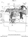
- Fig. 8 is a diagram illustrating the structure of an automobile 100 as a vehicle equipped with the engine E.
- the "front side” refers to the vehicle front side (specifically, the movement direction of the automobile 100) in the vehicle front and rear direction and the “rear side” refers to the vehicle rear side (specifically, the reverse movement direction of the automobile 100) in the vehicle front and rear direction.
- the "upper side” refers to the vehicle upper side in the vehicle height direction and the “lower side” refers to the vehicle lower side in the vehicle height direction.
- the “inner side” refers to the direction toward the engine E along the intake and exhaust direction and the “outer side” refers to the direction away from the engine E along the intake and exhaust direction.
- the automobile 100 is a so-called front engine/rear drive four-wheel vehicle (FR vehicle), which is a rear-wheel drive four-wheel vehicle having the engine E on the vehicle front side.
- FR vehicle front engine/rear drive four-wheel vehicle
- the automobile 100 illustrated in Fig. 8 includes a vehicle body 101, a pair of front wheels 102F, a pair of rear wheels 102R, the engine E mounted in the front portion of the vehicle body 101, a transmission 103 coupled to the rear portion of the engine E, and a propeller shaft 104 coupling the transmission 103 to the rear wheels 102R.
- the engine E is configured as a multi-cylinder longitudinal engine. Specifically, the engine E has a plurality of cylinders (six cylinders in the embodiment as indicated in drawings such as Figs. 5 and 6 ). The direction (cylinder row direction) in which the plurality of cylinders is arranged coincides with the extension direction (engine output shaft direction) of an engine output shaft Ac.
- the engine output shaft Ac is disposed in the vehicle front and rear direction. This engine output shaft Ac is disposed parallel to the propeller shaft 104.
- the transmission 103 is coupled to the rear portion of the engine E.
- the transmission 103 changes the number of revolutions of the engine output shaft Ac and transmits the changed number of revolutions to the propeller shaft 104.
- the propeller shaft 104 is disposed in the vehicle front and rear direction. Specifically, the propeller shaft 104 is not exactly parallel to the vehicle front and rear direction and inclined downward with respect to the vehicle front and rear direction. In particular, the propeller shaft 104 according to the embodiment extends toward the vehicle rear side while being inclined downward.
- the engine output shaft Ac of the engine E is also inclined downward.
- the engine E is mounted on the automobile 100 with the engine output shaft Ac inclined downward toward one side in the vehicle front and rear direction.
- the engine output shaft Ac according to the embodiment extends toward the vehicle rear side while being inclined downward (see inclination angle ⁇ c in Fig. 1 ) as illustrated in Fig. 1 .
- the engine E includes an engine body 1 having a plurality of cylinders and an intake device 2 that introduces intake air into the engine body 1.
- the intake device 2 has the intake passage structure according to the present disclosure.
- the engine body 1 is formed by combining a cylinder block 1a, a cylinder head 1b, and the like with each other.
- the engine body 1 includes the engine output shaft Ac inclined downward with respect to the vehicle front and rear direction and a plurality of cylinders arranged along the engine output shaft Ac.
- intake ports 11 leading to the cylinders are formed in the cylinder head 1b of the engine E as illustrated in Fig. 2 (see also Fig. 4 ). Entrance portions 11a as the upstream end portions of the intake ports 11 open in the intake side wall surface of the engine body 1.
- the "intake side wall surface” here corresponds to one wall surface (the left side surface of the engine body 1 in the embodiment) of the engine body 1 in the vehicle width direction.
- the intake device 2 includes, in order from the upstream side in the intake flow direction, an air cleaner (not illustrated), a throttle valve 3, a first intake pipe 4, an intercooler 5, a second intake pipe 6, a neck pipe 7, and a surge tank 8.
- the intake device 2 further includes an EGR gas introduction pipe 9 through which EGR gas flows back.
- the throttle valve 3 is disposed above the rear end portion of the surge tank 8. As indicated by arrow F1, the throttle valve 3 circulates the intake air obliquely downward and backward and can adjust the flow rate of the intake air.
- the first intake pipe 4 is connected to the throttle valve 3.
- the first intake pipe 4 is disposed behind the surge tank 8.
- the first intake pipe 4 is formed in a tubular shape extending substantially in the vertical direction.
- the first intake pipe 4 circulates intake air substantially downward as indicated by arrow F2.
- the intercooler 5 is connected to the lower end portion of the first intake pipe 4.
- the intercooler 5 is disposed on the lower side of the right half of the surge tank 8 and on the inner side of the neck pipe 7. As indicated by arrow F3, the intercooler 5 circulates the intake air from the vehicle rear side to the front side and can cool the intake air.
- the second intake pipe 6 is connected to the front end portion of the intercooler 5.
- the second intake pipe 6 is disposed on the lower side of the intercooler 5 with respect to the surge tank 8.
- the second intake pipe 6 is formed in a tubular shape extending substantially in the intake and exhaust direction.
- the second intake pipe 6 circulates the intake air having passed through the intercooler 5 substantially toward the outer side.
- the neck pipe 7 is connected to the end portion on the outer side of the second intake pipe 6.
- the lower portion of the second intake pipe 6 is provided with a pool portion 6a for storing the water flowing back through the neck pipe 7 into the second intake pipe 6.
- the neck pipe 7 is disposed below the surge tank 8, especially the middle portion in the front and rear direction of the surge tank 8.
- the neck pipe 7 is formed in a tubular shape extending in the vertical direction.
- the neck pipe 7 circulates the intake air having passed through the second intake pipe 6 upward as indicated by arrow F4.
- the surge tank 8 is connected to the upper end portion of the neck pipe 7.
- the EGR gas introduction pipe 9 is connected to the middle portion in the vertical direction of the neck pipe 7.
- the EGR gas introduction pipe 9 is disposed from the upper side to the outer side of the surge tank 8 and disposed on the rear side and the outer side of the neck pipe 7.
- the EGR gas introduction pipe 9 is formed in a tubular shape extending substantially in the vertical direction.
- the EGR gas introduction pipe 9 causes at least part of the exhaust gas generated by combustion in a cylinder to flow back and then be introduced into the neck pipe 7 as EGR gas as indicated by arrow F6.
- the surge tank 8 is attached to the entrance portions 11a of the intake ports 11.
- This surge tank 8 faces the entrance portions 11a with the branch pipes 83, which are part of the surge tank 8, sandwiched therebetween and is connected to the entrance portions 11a via the branch pipes 83. That is, the surge tank 8 according to the embodiment is directly connected to the entrance portions 11a via the branch pipes 83 integrated with the surge tank 8 without intervention of separate tubular members such as the first intake pipe 4 and the neck pipe 7.
- the surge tank 8 temporarily stores the intake air having passed through the neck pipe 7 and distributes this intake air to the individual cylinders.
- the inner peripheral surface of the surge tank 8 partitions a storage space S that extends in the cylinder row direction.
- This cylinder row direction coincides with the direction (engine output shaft direction) extending along the engine output shaft Ac as described above.
- the engine output shaft Ac is inclined downward with respect to the vehicle front and rear direction.
- the storage space S extending in the cylinder row direction is also inclined downward with respect to the vehicle front and rear direction.
- a ceiling surface 81a of the inner peripheral surface of the surge tank 8 extends parallel to the engine output shaft Ac as indicated by dot-dot-dash line as shown in Fig. 1 (for the ceiling surface 81a, see also drawings such as Figs. 4 and 5 ). More specifically, the ceiling surface 81a of the inner peripheral surface of the surge tank 8 is inclined downward toward the vehicle rear side.
- the surge tank 8 includes various ideas to solve the problems found when the ceiling surface 81a is inclined downward.
- the structure of the surge tank 8 will be described in detail below.
- the structure of the surge tank 8 may be used independently of the further features of the intake device 2 described so far.
- Fig. 5 is a diagram illustrating the structure of the upper half of the surge tank 8.
- Fig. 6 is a diagram illustrating the structure of the lower half of the surge tank 8.
- Fig. 7 is a diagram used to describe a flow of water along the surge tank 8.
- the surge tank 8 includes a first tank portion 81 which is the upper half of the surge tank 8 and a second tank portion 82 which is the lower half of the surge tank 8.
- the storage space S of the surge tank 8 is defined by the inner peripheral surfaces of the first tank portion 81 and the second tank portion 82. This storage space S is disposed at a position higher than the entrance portions 11a of the intake ports 11 in the vehicle height direction.
- the surge tank 8 also has the plurality of branch pipes 83 connected to the entry portions 11a of the intake ports 11, respectively.
- the plurality of branch pipes 83 is disposed so as to be arranged next to each other in the cylinder row direction. In a preferred embodiment, the plurality of branch pipes 83 is arranged at the same distance to the engine output shaft Ac.
- each of the branch pipes 83 extends from the storage space S toward an entrance portion 11a while being inclined downward along the intake and exhaust direction. Specifically, each of the branch pipes 83 extends substantially straight toward the lower side in the vehicle height direction from the outer side toward the inner side in the intake and exhaust direction.
- the dimensions in the vehicle front and rear direction and the cylinder row direction are larger than the dimensions in the intake and exhaust direction.
- the plurality of branch pipes 83 is provided integrally with the longer side portions that are located on the inner side in the intake and exhaust direction and extend in the cylinder row direction.
- the ceiling surface 81a inclined downward as described above of the inner peripheral surface of the surge tank 8 is formed by the inner peripheral surface of the first tank portion 81. As indicated by dot-dot-dash line Hc in Fig. 4 , this ceiling surface 81a is disposed at a position higher in the vehicle height direction than the upper surface of the inner peripheral surface in the entrance portions 11a of the intake ports 11.
- a bottom surface 82a of the inner peripheral surface of the surge tank 8 is formed by the inner peripheral surface of the second tank portion 82. As illustrated in Fig. 4 , this bottom surface 82a faces the ceiling surface 81a with a space.
- an introduction opening 82b through which air is introduced into the surge tank 8 is provided at the middle portion in the engine output shaft direction (cylinder row direction) of the bottom surface 82a.
- This introduction opening 82b is provided in a portion of the bottom surface 82a located on the outer side in the intake and exhaust direction.
- the downstream end portion of the neck pipe 7 is connected to the introduction opening 82b.
- the intake air having passed through the neck pipe 7 flows into the storage space S via the introduction opening 82b.
- the bottom surface 82a of the surge tank 8 is inclined downward toward the introduction opening 82b.
- first projecting portions 84 that extend in the intake and exhaust direction of the engine E and project toward the bottom surface 82a of the inner peripheral surface of the surge tank 8 on the ceiling surface 81a of the inner peripheral surface of the surge tank 8.
- each of the first projecting portions 84 is disposed in a space between two adjacent branch pipes 83 in the engine output shaft direction (cylinder row direction).
- the first projecting portions 84 are disposed in the space between the second branch pipe 83 (from the front side in the cylinder row direction) and the third branch pipe 83 and the space between the fourth branch pipe 83 and the fifth branch pipe 83.
- each of the first projection portions 84 includes an inner projection portion 84a disposed close to the entrance portion 11a of the intake port 11 in the intake and exhaust direction and an outer projecting portion 84b disposed relatively apart from the inner projection portion 84a.
- the inner projecting portion 84a is formed by denting the outer surface of the first tank portion 81 downward.
- the outer projecting portion 84b includes a rib-shaped projecting portion provided on the ceiling surface 81a. As illustrated in Fig. 5 , the inner projection portion 84a and the outer projecting portion 84b are connected integrally with each other in the intake and exhaust direction.
- the projection amount of the first projecting portion 84 increases as the first projecting portion 84 approaches the entrance portion 11a of the intake port 11 in the intake and exhaust direction.
- the projection amount (L1 to L3) of the inner projecting portion 84a of the first projecting portion 84 gradually increases toward the inner side from the outer side in the intake and exhaust direction. More specifically, a lower edge portion Lu of the inner projecting portion 84a extends substantially linearly while being inclined with respect to the intake and exhaust direction, as illustrated in Fig. 4 .
- This lower edge portion Lu is located at substantially the same height as the ceiling surface 81a on the outer side in the intake and exhaust direction and located at substantially the same height as the bottom surface of the upstream end portion 83a of the branch pipe 83 on the inner side in the intake and exhaust direction.
- the lower edge portion Lu of the inner projecting portion 84a extends substantially parallel to the branch pipes 83.
- the dimension of the first projecting portion 84 in the engine output shaft direction becomes larger as the first projecting portion 84 approaches the entrance portion 11a of the intake port 11 in the intake and exhaust direction.
- the dimension of the inner projecting portion 84a in the engine output shaft direction is larger than the dimension of the outer projecting portion 84b in the same direction when seen in the vehicle height direction as illustrated in Fig. 5 .
- the inner projecting portion 84a has a larger thickness in the engine output shaft direction than the outer projecting portion 84b.
- At least part of the first projecting portion 84 is offset so as to be close to the branch pipe 83 located on the vehicle front side among the plurality of branch pipes 83.
- the inner projecting portion 84a of the first projection portion 84 is disposed in the middle of the adjacent branch pipes 83.
- the outer projecting portion 84b of the first projection portion 84 is disposed close to the branch pipe 83 located on the vehicle front side among the adjacent branch pipes 83, as illustrated in Fig. 5 .
- second projecting portions 85 that extend in the intake and exhaust direction of the engine E and project toward the ceiling surface 81a of the inner peripheral surface of the surge tank 8 are formed on the bottom surface 82a of the inner peripheral surface of the surge tank 8.
- each of the second projecting portions 85 is disposed in the space between the plurality of branch pipes 83 in the engine output shaft direction (cylinder row direction). When seen in the vehicle height direction as illustrated in Fig. 6 , the second projecting portions 85 extend toward the introduction opening 82b while being inclined.
- each of the second projecting portions 85 is disposed in the space between the first branch pipe 83 (from the front side in the cylinder row direction) and the second branch pipe 83, the space between the second branch pipe 83 and the third branch pipe 83, the space between the third branch pipe 83 and the fourth branch pipe 83, the space between the fourth branch pipe 83 and the fifth branch pipe 83, and the space between the fifth branch pipe 83 and the sixth branch pipe 83.
- Fig. 7 is a diagram used to describe a flow of water along the surge tank 8.
- the cylinder row direction is also inclined downward.
- the ceiling surface 81a of the surge tank 8 is also inclined downward along the engine output shaft Ac and eventually the cylinder row direction, as illustrated by dot-dot-dash line Hc in Fig. 1 .
- the inventors of the present application and the like have found new problems specific to low temperature environments such as winter and cold regions as a result of clarifying the concerns about the surge tank 8 in which the ceiling surface 81a is inclined downward.
- icicles may be formed in the surge tank 8 because moisture in the air is frozen during parking.
- the icicles are melted after the engine E is started, but the water produced by the melting flows along the ceiling surface 81a inclined downward as described above and may be sucked unevenly into a specific cylinder through the intake port 11 located in the lowermost portion. Suction of water into a specific cylinder can lead to unfavorable events such as water hammer.
- the flow of water in the engine output shaft direction (cylinder row direction) on the ceiling surface 81a can be blocked (see arrow A1 in Fig. 7 ).
- the suction of water into a specific cylinder specifically, the cylinder located in the lowermost position
- the water produced by the melting of the icicles can be sucked into the individual cylinders evenly.
- the ceiling surface 81a at a position higher than the upper surface of the inner peripheral surface in the entrance portion 11a of the intake port 11, the height difference between the ceiling surface 81a of the surge tank 8 and the upper surface of the intake port 11 can be utilized. Accordingly, the flow of water blocked by the first projecting portions 84 can be smoothly guided to the cylinder close to the first projecting portions 84. This can achieve both smooth suction into the individual cylinders and the suppression of suction into a specific cylinder.
- the projection amount of the first projecting portions 84 is desirably made as large as possible to block the flow of water more reliably.
- the projection amount of the first projecting portions 84 is excessively large, the circulation of intake air in the surge tank 8 is obstructed and the distribution performance of intake air, which is the original function of the surge tank 8, may be impaired.
- the dimension of the first projecting portions 84 in the engine output shaft direction is desirably made as large as possible to block the flow of water more reliably.
- the dimension of the first projecting portions 84 is excessively large, the volume of the surge tank 8 becomes small and the distribution performance of the intake air, which is the original function of the surge tank 8, may be impaired.
- both the blocking performance of water by the first projection portions 84 and the distribution performance of the intake air can be obtained.
- the water blocked by the first projecting portion 84 flows along the second projecting portion 85 and reaches the introduction opening 82b.
- the water having reached the introduction opening 82b flows back through the neck pipe 7 and is stored in the pool section 6a of the second intake pipe 6.
- the first projecting portions 84 can block the water without interfering with the circulation of intake air through the branch pipes 83.
- the present disclosure is not limited to this structure.
- the engine output shaft Ac and eventually the ceiling surface 81a of the surge tank 8 may be inclined downward toward the vehicle front side in the vehicle front and rear direction so as to follow the bonnet line of the automobile 100.
- first projecting portion 84 extends parallel to the intake and exhaust direction as an example of the structure in which the first projecting portion 84 extends in the intake and exhaust direction as illustrated in Fig. 6 is disclosed in the embodiment described above, the present disclosure is not limited to this structure.
- the structure in which the first projecting portion 84 extends in the intake and exhaust direction for example, the structure in which the first projecting portion 84 extends while being slightly inclined with respect to the intake and exhaust direction may be adopted.
- the angle formed by the extension direction of the first projecting portion 84 and the intake and exhaust direction is preferably set to be smaller than the angle formed by the extension direction and the vehicle front and rear direction.
Landscapes
- Engineering & Computer Science (AREA)
- Chemical & Material Sciences (AREA)
- Combustion & Propulsion (AREA)
- Mechanical Engineering (AREA)
- General Engineering & Computer Science (AREA)
- Transportation (AREA)
- Physics & Mathematics (AREA)
- Geometry (AREA)
- Cooling, Air Intake And Gas Exhaust, And Fuel Tank Arrangements In Propulsion Units (AREA)
Description
- The present disclosure relates to an intake passage structure of an in-vehicle engine.
- For example,
JP-A-2020-2796 - In addition,
JP-A-2008-285999 JP-A-2008-285999 JP-A-2008-285999
EP 3 043 061 A1 discloses an intake system for an internal combustion engine. The intake system includes plural intake pipes being configured to be connected to cylinders of a main body of the internal combustion engine, respectively, an external gas distribution portion distributing a single type of an external gas to each of the plural intake pipes, a main body of the intake system including the plural intake pipes and the external gas distribution portion, and an external gas introduction passage being integrally formed with the main body of the intake system, the external gas introduction passage being configured to connect the main body of the internal combustion engine to the external gas distribution portion of the main body of the intake system, the external gas introduction passage serving as a single passage being configured to introduce the external gas from the main body of the internal combustion engine to the external gas distribution portion.
JP 2011 185 147 A
An air intake apparatus is known fromEP 3 480 449 A1 - By the way, when developing an in-vehicle engine (so-called "longitudinal engine") in which an engine output shaft is disposed in the vehicle front and rear direction, the inventors of the present application and the like have come up with the idea of inclining the engine output shaft downward toward one side (vehicle rear side or vehicle front side) in the vehicle front and rear direction instead of extending the engine output shaft parallel to the vehicle front and rear direction because of the layout of the propeller shaft and the like.
- When the engine output shaft is inclined downward, the cylinder row direction is also inclined downward. In this case, the ceiling surface of the surge tank described in the
patent documents - The inventors of the present application and the like have found new problems specific to low temperature environments such as winter and cold regions as a result of clarifying the concerns about the surge tank in which the ceiling surface is inclined downward. Specifically, for example, it is assumed that icicles are formed so as to extend from the ceiling surface of the surge tank because moisture in the air is frozen during parking. In this case, the icicles are melted after the engine is started, but the water produced by the melting flows along the ceiling surface inclined downward as described above and may be sucked unevenly into a specific cylinder through the intake port located in the lowermost portion. Suction of water into a specific cylinder can lead to unfavorable events such as water hammer.
- The technology disclosed herein addresses the problem described above with an object of causing the water produced by the melting of the icicles to be evenly sucked into the individual cylinders when the ceiling surface of the surge tank is inclined with respect to the engine output shaft.
- A first aspect of the present disclosure relates to a vehicle comprising an in-vehicle engine that has a plurality of cylinders and an engine output shaft disposed in a vehicle front and rear direction, the in-vehicle engine comprising an intake passage structure.
- According to the first aspect of the present disclosure, there is provided the intake passage structure of an in-vehicle engine, the intake passage structure including a surge tank attached to an entrance portion of an intake port formed in a cylinder head of the in-vehicle engine, a ceiling surface of an inner peripheral surface of the surge tank being inclined downward along the engine output shaft, a first projecting portion extending in an intake and exhaust direction of the in-vehicle engine and projecting toward a bottom surface of the inner peripheral surface of the surge tank being formed on the ceiling surface, in which the in-vehicle engine is mounted on a vehicle in a state in which the engine output shaft is inclined downward toward one side in the vehicle front and rear direction.
- Here, "extending in the intake and exhaust direction of the in-vehicle engine" includes "extending in a direction slightly inclined with respect to the intake and exhaust direction" in addition to "extending parallel to the intake and exhaust direction". Preferably, the angle formed by the extension direction of the first projecting portion and the intake and exhaust direction is smaller than the angle formed by the extension direction and the engine output shaft. The intake and exhaust direction preferably extends at an angle of 90° with respect to the extension direction of the engine output shaft. The angle formed by the extension direction of the first projecting portion and the extension direction of the engine output shaft is preferably bigger than 45°.
- According to the first aspect described above, by providing the first projecting portion on the ceiling surface of the surge tank and extending the first projecting portion in the intake and exhaust direction, the flow of water on the ceiling surface in the engine output shaft direction (cylinder row direction) can be blocked. By blocking the flow of water, the suction of water to a specific cylinder (specifically, the cylinder located in the lowermost position) can be suppressed. In this way, the water produced by the melting of icicles can be sucked into the individual cylinders evenly.
- In addition, according to a second aspect of the present disclosure, the ceiling surface may be disposed at a position higher in a vehicle height direction than an upper surface of an inner peripheral surface in the entrance portion of the intake port.
- According to the second aspect described above, by utilizing the height difference between the ceiling surface of the surge tank and the upper surface of the intake port, the flow of water blocked by the first projecting portion can be smoothly guided to the cylinder close to the first projecting portion. This can achieve both the smooth suction into the individual cylinders and the suppression of suction into a specific cylinder.
- In addition, according to a third aspect of the present disclosure, a projection amount of the first projecting portion may increase as the first projecting portion approaches the entrance portion of the intake port in the intake and exhaust direction.
- The projection amount of the first projecting portion is desirably made as large as possible to block the flow of water more reliably. However, when the projection amount of the first projecting portion is excessively large, the circulation of intake air in the surge tank is obstructed and the distribution performance of intake air, which is the original function of the
surge tank 8, may be hindered. - Accordingly, by making the projection amount of the first projecting portion different according to the distance from the entrance portion of the intake port as in the third aspect described above, both the blocking performance of water by the first projection portion and the distribution performance of the intake air can be obtained.
- In addition, according to a fourth aspect of the present disclosure, the projection amount of an inner projecting portion of the first projecting portion may gradually increase towards the entrance portion of the intake port.
- In an embodiment of the present invention, a lower edge portion of the inner projecting portion extends to the same height as the bottom surface of the upstream end portion of the branch pipe.
In an embodiment of the present invention, a lower edge portion of the inner projecting portion extends substantially linearly while being inclined with respect to the intake and exhaust direction. - In addition, according to a fifth aspect of the present disclosure, a dimension of the first projecting portion in an engine output shaft direction may be larger as the first projecting portion approaches the entrance portion of the intake port in the intake and exhaust direction.
- The dimension of the first projecting portion in the engine output shaft direction is desirably made as large as possible to block the flow of water more reliably. However, when the dimension of the first projecting portion is excessively large, the volume of the surge tank is reduced and the distribution performance of intake air, which is the original function of the
surge tank 8, may be hindered. - Accordingly, by making the dimension of the first projecting portion different according to the distance from the entrance portion of the intake port as in the fifth aspect described above, both the blocking performance of water by the first projection portion and the distribution performance of the intake air can be obtained.
According to the present invention, the first projection portion comprises an inner projecting portion and an outer projecting portion, wherein the inner projecting portion has a larger thickness in the engine output shaft direction than the outer projecting portion.
In an embodiment of the present invention, an inner projecting portion of the first projection portion may be formed by denting an outer surface of a first tank portion downward.
In an embodiment of the present invention, an outer projecting portion of the first projection portion includes a rib-shaped projecting portion provided on the ceiling surface.
In an embodiment of the present invention, the inner projection portion and the outer projecting portion are connected integrally with each other in the intake and exhaust direction. - In addition, according to a sixth aspect of the present disclosure, a second projecting portion that extends in the intake and exhaust direction and projects toward the ceiling surface may be formed on the bottom surface.
- According to the sixth aspect described above, when the water blocked by the first projecting portion drops on the bottom surface of the surge tank, the flow of water along the bottom surface can be blocked by the second projecting portion. This can suppress the suction of water into a specific cylinder.
- In addition, according to a seventh aspect of the present disclosure, an introduction opening through which air is introduced into the surge tank may be provided in a middle portion in the engine output shaft direction of the bottom surface.
In an embodiment of the present invention, the bottom surface is inclined downward toward the introduction opening.
In an embodiment of the present invention, the second projecting portion extends toward the introduction opening. - According to the seventh aspect described above, water can flow along the second projecting portion and the water can be guided to the introduction opening. This can discharge the water through the introduction opening.
- In addition, according to an eighth aspect of the present disclosure, the engine comprises a plurality of intake ports and the surge tank may have a plurality of branch pipes connected to the entrance portions of the intake ports.
In an embodiment of the present invention, the plurality of branch pipes is arranged so as to be inclined downward along the engine output shaft.
In an embodiment of the present invention, the first projecting portion is disposed in a space between two adjacent branch pipes in the engine output shaft direction. - According to the eighth aspect described above, by disposing each of the first projecting portions in the space between the adjacent branch pipes, the first projecting portions can block the water without interfering with the circulation of intake air through the branch pipes.
- In addition, according to a ninth aspect of the present disclosure, each of at least two first projection portions may be disposed in the space between respective adjacent branch pipes.
- In addition, according to a tenth aspect of the present disclosure, the second projection portion may be disposed in a space between adjacent branch pipes.
- In an embodiment of the present invention, each of at least two second projection portions is disposed in the space between respective adjacent branch pipes.
- In addition, according to an eleventh aspect of the present disclosure, at least part of the first projecting portion may be offset so as to be closer to the branch pipe located on a vehicle front side among the adjacent branch pipes.
- According to the eleventh aspect described above, the flow of water along the ceiling surface can be reliably blocked at an earlier timing.
- In addition, according to a twelfth aspect of the present disclosure, an inner projecting portion of the first projection portion may disposed in the middle of adjacent branch pipes.
- In an embodiment of the present invention, an outer projecting portion of the first projection portion is disposed closer to a branch pipe located on the vehicle front side among the adjacent branch pipes.
- In addition, according to a thirteenth aspect of the present disclosure, the surge tank may be such configured that water flowing along the ceiling surface is blocked in the engine output shaft direction by the at least one first projecting portion and is guided to a cylinder adjacent to the first projecting portions.
- In addition, according to a fourteenth aspect of the present disclosure, the surge tank is such configured that flow of water along the bottom surface is blocked by the second projecting portions and is guided to an introduction opening provided in a bottom surface of the surge tank.
- As described above, according to the present disclosure, when the ceiling surface of the surge tank is inclined with respect to the engine output shaft, the water produced by the melting of icicles can be sucked into the individual cylinders evenly.
-
- [
Fig. 1] Fig. 1 is a side view illustrating the structure of an engine. - [
Fig. 2] Fig. 2 is a front view illustrating the structure of the engine. - [
Fig. 3] Fig. 3 is a perspective view illustrating the structure of the engine. - [
Fig. 4] Fig. 4 is a sectional view illustrating the structure of the engine. - [
Fig. 5] Fig. 5 is a diagram illustrating the structure of the upper half of a surge tank. - [
Fig. 6] Fig. 6 is a diagram illustrating the structure of the lower half of the surge tank. - [
Fig. 7] Fig. 7 is a diagram used to describe a flow of water along the surge tank. - [
Fig. 8] Fig. 8 is a diagram illustrating the structure of a vehicle equipped with the engine. - Embodiments of the present disclosure will be described below with reference to the drawings. The following description is an example.
-
Fig. 1 is a side view illustrating the structure of an engine E as an in-vehicle engine. In addition,Fig. 2 is a front view illustrating the structure of the engine E,Fig. 3 is a perspective view illustrating the structure of the engine E, andFig. 4 is a sectional view illustrating the structure of the engine E. In addition,Fig. 8 is a diagram illustrating the structure of anautomobile 100 as a vehicle equipped with the engine E. - In the following description, the "front side" refers to the vehicle front side (specifically, the movement direction of the automobile 100) in the vehicle front and rear direction and the "rear side" refers to the vehicle rear side (specifically, the reverse movement direction of the automobile 100) in the vehicle front and rear direction.
- Similarly, the "upper side" refers to the vehicle upper side in the vehicle height direction and the "lower side" refers to the vehicle lower side in the vehicle height direction. In addition, the "inner side" refers to the direction toward the engine E along the intake and exhaust direction and the "outer side" refers to the direction away from the engine E along the intake and exhaust direction.
- As illustrated in
Fig. 8 , theautomobile 100 according to the embodiment is a so-called front engine/rear drive four-wheel vehicle (FR vehicle), which is a rear-wheel drive four-wheel vehicle having the engine E on the vehicle front side. Specifically, theautomobile 100 illustrated inFig. 8 includes avehicle body 101, a pair offront wheels 102F, a pair ofrear wheels 102R, the engine E mounted in the front portion of thevehicle body 101, atransmission 103 coupled to the rear portion of the engine E, and apropeller shaft 104 coupling thetransmission 103 to therear wheels 102R. - The engine E is configured as a multi-cylinder longitudinal engine. Specifically, the engine E has a plurality of cylinders (six cylinders in the embodiment as indicated in drawings such as
Figs. 5 and6 ). The direction (cylinder row direction) in which the plurality of cylinders is arranged coincides with the extension direction (engine output shaft direction) of an engine output shaft Ac. In the engine E, which is a longitudinal engine, the engine output shaft Ac is disposed in the vehicle front and rear direction. This engine output shaft Ac is disposed parallel to thepropeller shaft 104. - The
transmission 103 is coupled to the rear portion of the engine E. Thetransmission 103 changes the number of revolutions of the engine output shaft Ac and transmits the changed number of revolutions to thepropeller shaft 104. - The
propeller shaft 104 is disposed in the vehicle front and rear direction. Specifically, thepropeller shaft 104 is not exactly parallel to the vehicle front and rear direction and inclined downward with respect to the vehicle front and rear direction. In particular, thepropeller shaft 104 according to the embodiment extends toward the vehicle rear side while being inclined downward. - As the
propeller shaft 104 is inclined downward, the engine output shaft Ac of the engine E is also inclined downward. Specifically, the engine E is mounted on theautomobile 100 with the engine output shaft Ac inclined downward toward one side in the vehicle front and rear direction. In particular, the engine output shaft Ac according to the embodiment extends toward the vehicle rear side while being inclined downward (see inclination angle θc inFig. 1 ) as illustrated inFig. 1 . - As illustrated in
Figs. 1 to 3 , the engine E includes anengine body 1 having a plurality of cylinders and anintake device 2 that introduces intake air into theengine body 1. Of the components of the engine E, theintake device 2 has the intake passage structure according to the present disclosure. - The
engine body 1 is formed by combining acylinder block 1a, acylinder head 1b, and the like with each other. Theengine body 1 includes the engine output shaft Ac inclined downward with respect to the vehicle front and rear direction and a plurality of cylinders arranged along the engine output shaft Ac. - Here,
intake ports 11 leading to the cylinders are formed in thecylinder head 1b of the engine E as illustrated inFig. 2 (see alsoFig. 4 ).Entrance portions 11a as the upstream end portions of theintake ports 11 open in the intake side wall surface of theengine body 1. The "intake side wall surface" here corresponds to one wall surface (the left side surface of theengine body 1 in the embodiment) of theengine body 1 in the vehicle width direction. - As illustrated in
Figs. 1 to 3 , theintake device 2 includes, in order from the upstream side in the intake flow direction, an air cleaner (not illustrated), athrottle valve 3, afirst intake pipe 4, anintercooler 5, asecond intake pipe 6, aneck pipe 7, and asurge tank 8. Theintake device 2 further includes an EGRgas introduction pipe 9 through which EGR gas flows back. - The
throttle valve 3 is disposed above the rear end portion of thesurge tank 8. As indicated by arrow F1, thethrottle valve 3 circulates the intake air obliquely downward and backward and can adjust the flow rate of the intake air. Thefirst intake pipe 4 is connected to thethrottle valve 3. - The
first intake pipe 4 is disposed behind thesurge tank 8. Thefirst intake pipe 4 is formed in a tubular shape extending substantially in the vertical direction. Thefirst intake pipe 4 circulates intake air substantially downward as indicated by arrow F2. Theintercooler 5 is connected to the lower end portion of thefirst intake pipe 4. - The
intercooler 5 is disposed on the lower side of the right half of thesurge tank 8 and on the inner side of theneck pipe 7. As indicated by arrow F3, theintercooler 5 circulates the intake air from the vehicle rear side to the front side and can cool the intake air. Thesecond intake pipe 6 is connected to the front end portion of theintercooler 5. - As illustrated in, for example,
Fig. 2 , thesecond intake pipe 6 is disposed on the lower side of theintercooler 5 with respect to thesurge tank 8. Thesecond intake pipe 6 is formed in a tubular shape extending substantially in the intake and exhaust direction. Thesecond intake pipe 6 circulates the intake air having passed through theintercooler 5 substantially toward the outer side. Theneck pipe 7 is connected to the end portion on the outer side of thesecond intake pipe 6. In addition, the lower portion of thesecond intake pipe 6 is provided with apool portion 6a for storing the water flowing back through theneck pipe 7 into thesecond intake pipe 6. - The
neck pipe 7 is disposed below thesurge tank 8, especially the middle portion in the front and rear direction of thesurge tank 8. Theneck pipe 7 is formed in a tubular shape extending in the vertical direction. Theneck pipe 7 circulates the intake air having passed through thesecond intake pipe 6 upward as indicated by arrow F4. Thesurge tank 8 is connected to the upper end portion of theneck pipe 7. In addition, the EGRgas introduction pipe 9 is connected to the middle portion in the vertical direction of theneck pipe 7. - The EGR
gas introduction pipe 9 is disposed from the upper side to the outer side of thesurge tank 8 and disposed on the rear side and the outer side of theneck pipe 7. The EGRgas introduction pipe 9 is formed in a tubular shape extending substantially in the vertical direction. The EGRgas introduction pipe 9 causes at least part of the exhaust gas generated by combustion in a cylinder to flow back and then be introduced into theneck pipe 7 as EGR gas as indicated by arrow F6. - The
surge tank 8 is attached to theentrance portions 11a of theintake ports 11. Thissurge tank 8 faces theentrance portions 11a with thebranch pipes 83, which are part of thesurge tank 8, sandwiched therebetween and is connected to theentrance portions 11a via thebranch pipes 83. That is, thesurge tank 8 according to the embodiment is directly connected to theentrance portions 11a via thebranch pipes 83 integrated with thesurge tank 8 without intervention of separate tubular members such as thefirst intake pipe 4 and theneck pipe 7. As indicated by arrow F5, thesurge tank 8 temporarily stores the intake air having passed through theneck pipe 7 and distributes this intake air to the individual cylinders. - The inner peripheral surface of the
surge tank 8 partitions a storage space S that extends in the cylinder row direction. This cylinder row direction coincides with the direction (engine output shaft direction) extending along the engine output shaft Ac as described above. In contrast, the engine output shaft Ac is inclined downward with respect to the vehicle front and rear direction. Accordingly, the storage space S extending in the cylinder row direction is also inclined downward with respect to the vehicle front and rear direction. - Specifically, a
ceiling surface 81a of the inner peripheral surface of thesurge tank 8 extends parallel to the engine output shaft Ac as indicated by dot-dot-dash line as shown inFig. 1 (for theceiling surface 81a, see also drawings such asFigs. 4 and5 ). More specifically, theceiling surface 81a of the inner peripheral surface of thesurge tank 8 is inclined downward toward the vehicle rear side. - The
surge tank 8 according to the embodiment includes various ideas to solve the problems found when theceiling surface 81a is inclined downward. The structure of thesurge tank 8 will be described in detail below. The structure of thesurge tank 8 may be used independently of the further features of theintake device 2 described so far. -
Fig. 5 is a diagram illustrating the structure of the upper half of thesurge tank 8.Fig. 6 is a diagram illustrating the structure of the lower half of thesurge tank 8.Fig. 7 is a diagram used to describe a flow of water along thesurge tank 8. - Returning to
Figs. 2 to 4 , thesurge tank 8 according to the embodiment includes afirst tank portion 81 which is the upper half of thesurge tank 8 and asecond tank portion 82 which is the lower half of thesurge tank 8. - The storage space S of the
surge tank 8 is defined by the inner peripheral surfaces of thefirst tank portion 81 and thesecond tank portion 82. This storage space S is disposed at a position higher than theentrance portions 11a of theintake ports 11 in the vehicle height direction. - The
surge tank 8 also has the plurality ofbranch pipes 83 connected to theentry portions 11a of theintake ports 11, respectively. The plurality ofbranch pipes 83 is disposed so as to be arranged next to each other in the cylinder row direction. In a preferred embodiment, the plurality ofbranch pipes 83 is arranged at the same distance to the engine output shaft Ac. - As illustrated in
Fig. 4 , each of thebranch pipes 83 extends from the storage space S toward anentrance portion 11a while being inclined downward along the intake and exhaust direction. Specifically, each of thebranch pipes 83 extends substantially straight toward the lower side in the vehicle height direction from the outer side toward the inner side in the intake and exhaust direction. - As illustrated in
Figs. 5 and6 , in both thefirst tank portion 81 and thesecond tank portion 82, the dimensions in the vehicle front and rear direction and the cylinder row direction are larger than the dimensions in the intake and exhaust direction. In thefirst tank portion 81 and thesecond tank portion 82, the plurality ofbranch pipes 83 is provided integrally with the longer side portions that are located on the inner side in the intake and exhaust direction and extend in the cylinder row direction. - The
ceiling surface 81a inclined downward as described above of the inner peripheral surface of thesurge tank 8 is formed by the inner peripheral surface of thefirst tank portion 81. As indicated by dot-dot-dash line Hc inFig. 4 , thisceiling surface 81a is disposed at a position higher in the vehicle height direction than the upper surface of the inner peripheral surface in theentrance portions 11a of theintake ports 11. - In contrast, a
bottom surface 82a of the inner peripheral surface of thesurge tank 8 is formed by the inner peripheral surface of thesecond tank portion 82. As illustrated inFig. 4 , thisbottom surface 82a faces theceiling surface 81a with a space. - In addition, as illustrated in
Fig. 6 , an introduction opening 82b through which air is introduced into thesurge tank 8 is provided at the middle portion in the engine output shaft direction (cylinder row direction) of thebottom surface 82a. This introduction opening 82b is provided in a portion of thebottom surface 82a located on the outer side in the intake and exhaust direction. The downstream end portion of theneck pipe 7 is connected to theintroduction opening 82b. The intake air having passed through theneck pipe 7 flows into the storage space S via theintroduction opening 82b. In addition, in a cross section (cross section illustrated inFig. 4 ) orthogonal to the engine output shaft Ac, thebottom surface 82a of thesurge tank 8 is inclined downward toward theintroduction opening 82b. - As illustrated in
Figs. 4 and5 , there are first projectingportions 84 that extend in the intake and exhaust direction of the engine E and project toward thebottom surface 82a of the inner peripheral surface of thesurge tank 8 on theceiling surface 81a of the inner peripheral surface of thesurge tank 8. - Specifically, each of the first projecting
portions 84 is disposed in a space between twoadjacent branch pipes 83 in the engine output shaft direction (cylinder row direction). In the example illustrated inFig. 5 , the first projectingportions 84 are disposed in the space between the second branch pipe 83 (from the front side in the cylinder row direction) and thethird branch pipe 83 and the space between thefourth branch pipe 83 and thefifth branch pipe 83. - In addition, each of the
first projection portions 84 according to the embodiment includes aninner projection portion 84a disposed close to theentrance portion 11a of theintake port 11 in the intake and exhaust direction and an outer projectingportion 84b disposed relatively apart from theinner projection portion 84a. - In the embodiment, the inner projecting
portion 84a is formed by denting the outer surface of thefirst tank portion 81 downward. In contrast, the outer projectingportion 84b includes a rib-shaped projecting portion provided on theceiling surface 81a. As illustrated inFig. 5 , theinner projection portion 84a and the outer projectingportion 84b are connected integrally with each other in the intake and exhaust direction. - In addition, as indicated by double-headed arrows L1, L2, and L3 in
Fig. 4 , the projection amount of the first projectingportion 84 increases as the first projectingportion 84 approaches theentrance portion 11a of theintake port 11 in the intake and exhaust direction. - Specifically, in the embodiment, the projection amount (L1 to L3) of the inner projecting
portion 84a of the first projectingportion 84 gradually increases toward the inner side from the outer side in the intake and exhaust direction. More specifically, a lower edge portion Lu of the inner projectingportion 84a extends substantially linearly while being inclined with respect to the intake and exhaust direction, as illustrated inFig. 4 . This lower edge portion Lu is located at substantially the same height as theceiling surface 81a on the outer side in the intake and exhaust direction and located at substantially the same height as the bottom surface of theupstream end portion 83a of thebranch pipe 83 on the inner side in the intake and exhaust direction. The lower edge portion Lu of the inner projectingportion 84a extends substantially parallel to thebranch pipes 83. - In addition, as illustrated in
Fig. 5 , the dimension of the first projectingportion 84 in the engine output shaft direction (cylinder row direction) becomes larger as the first projectingportion 84 approaches theentrance portion 11a of theintake port 11 in the intake and exhaust direction. - Specifically, in the embodiment, the dimension of the inner projecting
portion 84a in the engine output shaft direction is larger than the dimension of the outer projectingportion 84b in the same direction when seen in the vehicle height direction as illustrated inFig. 5 . In other words, the inner projectingportion 84a has a larger thickness in the engine output shaft direction than the outer projectingportion 84b. - In addition, as illustrated in
Fig. 5 , at least part of the first projectingportion 84 is offset so as to be close to thebranch pipe 83 located on the vehicle front side among the plurality ofbranch pipes 83. - Specifically, in the embodiment, the inner projecting
portion 84a of thefirst projection portion 84 is disposed in the middle of theadjacent branch pipes 83. In contrast, the outer projectingportion 84b of thefirst projection portion 84 is disposed close to thebranch pipe 83 located on the vehicle front side among theadjacent branch pipes 83, as illustrated inFig. 5 . - In contrast, as illustrated in
Figs. 4 and6 , second projectingportions 85 that extend in the intake and exhaust direction of the engine E and project toward theceiling surface 81a of the inner peripheral surface of thesurge tank 8 are formed on thebottom surface 82a of the inner peripheral surface of thesurge tank 8. - Specifically, each of the second projecting
portions 85 is disposed in the space between the plurality ofbranch pipes 83 in the engine output shaft direction (cylinder row direction). When seen in the vehicle height direction as illustrated inFig. 6 , the second projectingportions 85 extend toward theintroduction opening 82b while being inclined. - In the example illustrated in
Fig. 6 , each of the second projectingportions 85 is disposed in the space between the first branch pipe 83 (from the front side in the cylinder row direction) and thesecond branch pipe 83, the space between thesecond branch pipe 83 and thethird branch pipe 83, the space between thethird branch pipe 83 and thefourth branch pipe 83, the space between thefourth branch pipe 83 and thefifth branch pipe 83, and the space between thefifth branch pipe 83 and thesixth branch pipe 83. -
Fig. 7 is a diagram used to describe a flow of water along thesurge tank 8. - By the way, when the engine output shaft Ac is inclined downward as described above, the cylinder row direction is also inclined downward. In this case, the
ceiling surface 81a of thesurge tank 8 is also inclined downward along the engine output shaft Ac and eventually the cylinder row direction, as illustrated by dot-dot-dash line Hc inFig. 1 . - The inventors of the present application and the like have found new problems specific to low temperature environments such as winter and cold regions as a result of clarifying the concerns about the
surge tank 8 in which theceiling surface 81a is inclined downward. Specifically, for example, it is assumed that icicles may be formed in thesurge tank 8 because moisture in the air is frozen during parking. In this case, the icicles are melted after the engine E is started, but the water produced by the melting flows along theceiling surface 81a inclined downward as described above and may be sucked unevenly into a specific cylinder through theintake port 11 located in the lowermost portion. Suction of water into a specific cylinder can lead to unfavorable events such as water hammer. - In contrast, according to the embodiment, by providing the first projecting
portions 84 on theceiling surface 81a of thesurge tank 8 and extending the first projectingportions 84 in the intake and exhaust direction as illustrated inFig. 4 , the flow of water in the engine output shaft direction (cylinder row direction) on theceiling surface 81a can be blocked (see arrow A1 inFig. 7 ). By blocking the flow of water, the suction of water into a specific cylinder (specifically, the cylinder located in the lowermost position) can be suppressed. In this way, the water produced by the melting of the icicles can be sucked into the individual cylinders evenly. - In addition, as illustrated in
Fig. 4 , by disposing theceiling surface 81a at a position higher than the upper surface of the inner peripheral surface in theentrance portion 11a of theintake port 11, the height difference between theceiling surface 81a of thesurge tank 8 and the upper surface of theintake port 11 can be utilized. Accordingly, the flow of water blocked by the first projectingportions 84 can be smoothly guided to the cylinder close to the first projectingportions 84. This can achieve both smooth suction into the individual cylinders and the suppression of suction into a specific cylinder. - By the way, the projection amount of the first projecting
portions 84 is desirably made as large as possible to block the flow of water more reliably. In contrast, when the projection amount of the first projectingportions 84 is excessively large, the circulation of intake air in thesurge tank 8 is obstructed and the distribution performance of intake air, which is the original function of thesurge tank 8, may be impaired. - Accordingly, as indicated by double-headed arrows L1 to L3 in
Fig. 4 , by making the projection amount of the first projectingportions 84 different according to the distance from theentrance portion 11a of theintake port 11, both the blocking performance of water by the first projectingportions 84 and the distribution performance of intake air can be obtained. - In addition, the dimension of the first projecting
portions 84 in the engine output shaft direction is desirably made as large as possible to block the flow of water more reliably. In contrast, when the dimension of the first projectingportions 84 is excessively large, the volume of thesurge tank 8 becomes small and the distribution performance of the intake air, which is the original function of thesurge tank 8, may be impaired. - Accordingly, as illustrated in
Fig. 5 , by making the dimension of the first projectingportions 84 different (specifically, by making the dimension in the engine output shaft direction different between the outer projectingportions 84b and the inner projectingportions 84a) according to the distance from theentrance portion 11a of theintake port 11, both the blocking performance of water by thefirst projection portions 84 and the distribution performance of the intake air can be obtained. - In addition, as illustrated in
Fig. 4 , by providing the second projectingportions 85 on thebottom surface 82a of thesurge tank 8 and extending the second projectingportions 85 in the intake and exhaust direction, when the water blocked by the first projectingportions 84 drops on thebottom surface 82a of thesurge tank 8, the flow of the water along thebottom surface 82a can be blocked by the second projecting portions 85 (see arrow A2 inFig. 7 ). Accordingly, the suction of the water into a specific cylinder can be suppressed. - In addition, as illustrated in
Fig. 6 , by extending the second projectingportions 85 toward theintroduction opening 82b, water can flow along the second projectingportion 85 and the water can be guided to theintroduction opening 82b. This can discharge the water through theintroduction opening 82b. - Specifically, as illustrated by arrows A1 and A2 in
Fig. 7 , the water blocked by the first projectingportion 84 flows along the second projectingportion 85 and reaches theintroduction opening 82b. The water having reached the introduction opening 82b flows back through theneck pipe 7 and is stored in thepool section 6a of thesecond intake pipe 6. - In addition, as illustrated in
Fig. 5 , by disposing each of the first projectingportions 84 in the space between twoadjacent branch pipes 83, the first projectingportions 84 can block the water without interfering with the circulation of intake air through thebranch pipes 83. - Although the embodiment described above adopts the structure in which the engine output shaft Ac and eventually the
ceiling surface 81a of and thesurge tank 8 are inclined downward toward the vehicle rear side in the vehicle front and rear direction, the present disclosure is not limited to this structure. For example, the engine output shaft Ac and eventually theceiling surface 81a of thesurge tank 8 may be inclined downward toward the vehicle front side in the vehicle front and rear direction so as to follow the bonnet line of theautomobile 100. - In addition, although the structure in which the first projecting
portion 84 extends parallel to the intake and exhaust direction as an example of the structure in which the first projectingportion 84 extends in the intake and exhaust direction as illustrated inFig. 6 is disclosed in the embodiment described above, the present disclosure is not limited to this structure. - As another example of the structure in which the first projecting
portion 84 extends in the intake and exhaust direction, for example, the structure in which the first projectingportion 84 extends while being slightly inclined with respect to the intake and exhaust direction may be adopted. When using this structure, the angle formed by the extension direction of the first projectingportion 84 and the intake and exhaust direction is preferably set to be smaller than the angle formed by the extension direction and the vehicle front and rear direction. -
- E: engine (in-vehicle engine)
- 1: engine body
- 1a: cylinder block
- 1b: cylinder head
- 11: intake port
- 11a: entrance portion of intake port
- 2: intake device
- 8: surge tank
- 81: first tank portion
- 81a: ceiling surface of surge tank
- 82: second tank portion
- 82a: bottom surface of surge tank
- 82b: introduction opening
- 83: branch pipe
- 84: first projecting portion
- 84a: inner projecting portion
- 84b: outer projecting portion
- 85: second projecting portion
- 100: automobile (vehicle)
- Ac: engine output shaft
- Hc: height of ceiling surface
- L1: projection amount of first projecting portion
- L2: projection amount of first projecting portion
- L3: projection amount of first projecting portion
Claims (14)
- Vehicle (100) comprising a vehicle-mounted engine (E) that has a plurality of cylinders and an engine output shaft (Ac) disposed in a vehicle front and rear direction, the vehicle-mounted engine (E) comprising an intake passage structure,wherein the vehicle-mounted engine (E) is mounted on the vehicle (100) in a state in which the engine output shaft (Ac) is inclined downward toward one side in the vehicle front and rear direction, andwherein the intake passage structure comprises a surge tank (8) attached to an entrance portion (11a) of an intake port (11) formed in a cylinder head (1b) of the vehicle-mounted engine (E),characterized in thata ceiling surface (81a) of an inner peripheral surface of the surge tank (8) is inclined downward along the engine output shaft (Ac), anda first projecting portion (84) extending in an intake and exhaust direction of the vehicle-mounted engine (E) and projecting toward a bottom surface (82a) of the inner peripheral surface of the surge tank (8) is formed on the ceiling surface (81a),wherein the first projection portion (84) comprises an inner projecting portion (84a) and an outer projecting portion (84b), wherein the inner projecting portion (84a) has a larger thickness in the engine output shaft direction than the outer projecting portion (84b),wherein preferably the outer projecting portion (84b) includes a rib-shaped projecting portion provided on the ceiling surface (81a).
- The vehicle (100) according to claim 1,
wherein the ceiling surface (81a) is disposed at a position higher in a vehicle height direction than an upper surface of an inner peripheral surface in the entrance portion (11a) of the intake port (11). - The vehicle (100) according to claim 1 or 2,
wherein a projection amount (L1 to L3) of the first projecting portion (84) increases as the first projecting portion (84) approaches the entrance portion (11a) of the intake port (11) in the intake and exhaust direction. - The vehicle (100) according to claim 3,wherein the projection amount (L1 to L3) of an inner projecting portion (84a) of the first projecting portion (84) gradually increases toward the entrance portion (11a) of the intake port (11),and/or wherein a lower edge portion (Lu) of the inner projecting portion (84a) extends to the same height as the bottom surface of the upstream end portion (83a) of the branch pipe (83).
- The vehicle (100) according to any one of claims 1 to 4,
wherein a dimension of the first projecting portion (84) in an engine output shaft direction is larger as the first projecting portion (84) approaches the entrance portion (11a) of the intake port (11) in the intake and exhaust direction. - The vehicle (100) according to any one of claims 1 to 5,
wherein a second projecting portion (85) that extends in the intake and exhaust direction and projects toward the ceiling surface (81a) is formed on the bottom surface (82a). - The vehicle (100) according to claim 6,wherein an introduction opening (82b) through which air is introduced into the surge tank (8) is provided in a middle portion in the engine output shaft direction of the bottom surface (82a),wherein preferably the bottom surface (82a) is inclined downward toward the introduction opening (82b), andwherein preferably the second projecting portion (85) extends toward the introduction opening (82b).
- The vehicle (100) according to any one of claims 1 to 7,wherein the engine comprises a plurality of intake ports (11) and the surge tank (8) has a plurality of branch pipes (83) connected to entrance portions (11a) of the intake ports (11),wherein preferably the first projecting portion (84) is disposed in a space between two adjacent branch pipes (83) in the engine output shaft direction.
- The vehicle (100) according to claim 8,
wherein each of at least two first projection portions (84) is disposed in the space between respective adjacent branch pipes (83). - The vehicle (100) according to claim 6 and 8,wherein the second projection portion (85) is disposed in a space between adjacent branch pipes (83),wherein preferably each of at least two second projection portions (85) is disposed in the space between respective adjacent branch pipes (83).
- The vehicle (100) according to claim 8,
wherein at least part of the first projecting portion (84) is offset so as to be closer to the branch pipe (83) located on a vehicle front side among the adjacent branch pipes (83). - The vehicle (100) according to claim 11,wherein an inner projecting portion (84a) of the first projection portion (84) is disposed in the middle of adjacent branch pipes (83),wherein preferably an outer projecting portion (84b) of the first projection portion (84) is disposed closer to a branch pipe (83) located on the vehicle front side among the adjacent branch pipes (83).
- The vehicle (100) according to any preceding claim,
wherein the surge tank (8) is such configured that water flowing along the ceiling surface (81a) is blocked in the engine output shaft direction by the at least one first projecting portion (84) and is guided to a cylinder adjacent to the first projecting portions (84). - The vehicle (100) according to any preceding claim, wherein the surge tank (8) is such configured that flow of water along the bottom surface (82a) is blocked by the second projecting portions (85) and is guided to an introduction opening (82b) being provided in a bottom surface (82a) of the surge tank (8).
Applications Claiming Priority (1)
| Application Number | Priority Date | Filing Date | Title |
|---|---|---|---|
| JP2020074093A JP7456258B2 (en) | 2020-04-17 | 2020-04-17 | Intake passage structure for vehicle engine |
Publications (2)
| Publication Number | Publication Date |
|---|---|
| EP3896275A1 EP3896275A1 (en) | 2021-10-20 |
| EP3896275B1 true EP3896275B1 (en) | 2023-04-26 |
Family
ID=75108241
Family Applications (1)
| Application Number | Title | Priority Date | Filing Date |
|---|---|---|---|
| EP21163475.3A Active EP3896275B1 (en) | 2020-04-17 | 2021-03-18 | Vehicle with engine intake passage structure |
Country Status (2)
| Country | Link |
|---|---|
| EP (1) | EP3896275B1 (en) |
| JP (1) | JP7456258B2 (en) |
Families Citing this family (2)
| Publication number | Priority date | Publication date | Assignee | Title |
|---|---|---|---|---|
| JP7775732B2 (en) * | 2022-01-31 | 2025-11-26 | マツダ株式会社 | Engine intake system |
| CN117514547A (en) * | 2022-07-29 | 2024-02-06 | 比亚迪股份有限公司 | Engine air intake components, engines and vehicles |
Family Cites Families (13)
| Publication number | Priority date | Publication date | Assignee | Title |
|---|---|---|---|---|
| DE3500024C2 (en) * | 1984-08-16 | 1994-03-10 | Toyota Motor Co Ltd | Intake system for a multi-cylinder internal combustion engine |
| JP2000087816A (en) * | 1998-09-16 | 2000-03-28 | Suzuki Motor Corp | Engine intake system |
| JP3953437B2 (en) * | 2003-04-09 | 2007-08-08 | 愛三工業株式会社 | Resin intake manifold |
| KR100645576B1 (en) * | 2004-07-06 | 2006-11-15 | 현대자동차주식회사 | Automotive Air Intake System |
| JP4420064B2 (en) * | 2007-05-15 | 2010-02-24 | 株式会社デンソー | Intake manifold |
| JP5440271B2 (en) * | 2010-03-08 | 2014-03-12 | 株式会社デンソー | Intake manifold for vehicles |
| JP2016125467A (en) * | 2015-01-08 | 2016-07-11 | アイシン精機株式会社 | Suction device of internal combustion engine |
| JP6501184B2 (en) * | 2015-04-30 | 2019-04-17 | ダイハツ工業株式会社 | Internal combustion engine for vehicles |
| EP3306048A1 (en) * | 2016-10-05 | 2018-04-11 | MANN+HUMMEL GmbH | Air duct arrangement and cooler |
| JP2018145822A (en) * | 2017-03-02 | 2018-09-20 | トヨタ自動車株式会社 | Internal combustion engine |
| JP6583387B2 (en) * | 2017-11-07 | 2019-10-02 | マツダ株式会社 | Multi-cylinder engine intake system |
| JP6536654B2 (en) * | 2017-11-07 | 2019-07-03 | マツダ株式会社 | Multi-cylinder engine intake system |
| JP7151208B2 (en) * | 2018-06-25 | 2022-10-12 | マツダ株式会社 | Intake system for multi-cylinder engine |
-
2020
- 2020-04-17 JP JP2020074093A patent/JP7456258B2/en active Active
-
2021
- 2021-03-18 EP EP21163475.3A patent/EP3896275B1/en active Active
Also Published As
| Publication number | Publication date |
|---|---|
| JP7456258B2 (en) | 2024-03-27 |
| EP3896275A1 (en) | 2021-10-20 |
| JP2021169813A (en) | 2021-10-28 |
Similar Documents
| Publication | Publication Date | Title |
|---|---|---|
| CN1298968C (en) | Internal-combustion eugine with cylinder mixing air recycle system | |
| JP6536654B2 (en) | Multi-cylinder engine intake system | |
| EP3051096B1 (en) | Intake gas cooling device for supercharged internal combustion engine | |
| EP3896275B1 (en) | Vehicle with engine intake passage structure | |
| US6823968B2 (en) | Oil collecting arrangement for an internal-combustion engine, particularly for an opposed-cylinder engine | |
| KR20050036056A (en) | An air intake system in automobile | |
| EP2123896B1 (en) | Intake manifold for multi-cylinder internal combustion engine | |
| EP3456952B1 (en) | Intake apparatus for internal combustion engine | |
| EP1211399B1 (en) | Suction device used for internal combustion engine | |
| JPH0723696B2 (en) | Engine intake system | |
| JP2019085920A (en) | Intake device of multicylinder engine | |
| CN101182800B (en) | Multi-cylinder engine intake system | |
| US7814877B2 (en) | Intake manifold with reinforcing partitions | |
| JP2008223738A (en) | Intake manifold for multi-cylinder internal combustion engines | |
| JP4814164B2 (en) | Intake device for internal combustion engine | |
| JP2002168153A (en) | Intake device for internal combustion engine | |
| JP7604990B2 (en) | Intake system for internal combustion engine | |
| JPH0417805Y2 (en) | ||
| JP4027547B2 (en) | EGR device | |
| JP2000220540A (en) | Intake manifold structure | |
| JP3431946B2 (en) | Inlet structure of front and rear V-type two-stroke engine of motorcycle | |
| JPH0417804Y2 (en) | ||
| JP2008038858A (en) | Intake device for vehicle engine | |
| JP2599254B2 (en) | V-type engine intake system | |
| JPH01117921A (en) | Intake device of v-shaped engine |
Legal Events
| Date | Code | Title | Description |
|---|---|---|---|
| PUAI | Public reference made under article 153(3) epc to a published international application that has entered the european phase |
Free format text: ORIGINAL CODE: 0009012 |
|
| STAA | Information on the status of an ep patent application or granted ep patent |
Free format text: STATUS: THE APPLICATION HAS BEEN PUBLISHED |
|
| AK | Designated contracting states |
Kind code of ref document: A1 Designated state(s): AL AT BE BG CH CY CZ DE DK EE ES FI FR GB GR HR HU IE IS IT LI LT LU LV MC MK MT NL NO PL PT RO RS SE SI SK SM TR |
|
| B565 | Issuance of search results under rule 164(2) epc |
Effective date: 20210624 |
|
| STAA | Information on the status of an ep patent application or granted ep patent |
Free format text: STATUS: REQUEST FOR EXAMINATION WAS MADE |
|
| 17P | Request for examination filed |
Effective date: 20220328 |
|
| RBV | Designated contracting states (corrected) |
Designated state(s): AL AT BE BG CH CY CZ DE DK EE ES FI FR GB GR HR HU IE IS IT LI LT LU LV MC MK MT NL NO PL PT RO RS SE SI SK SM TR |
|
| GRAP | Despatch of communication of intention to grant a patent |
Free format text: ORIGINAL CODE: EPIDOSNIGR1 |
|
| STAA | Information on the status of an ep patent application or granted ep patent |
Free format text: STATUS: GRANT OF PATENT IS INTENDED |
|
| RIC1 | Information provided on ipc code assigned before grant |
Ipc: B60K 17/22 19680901ALI20230105BHEP Ipc: B60K 13/02 19680901ALI20230105BHEP Ipc: B60K 5/02 19680901ALI20230105BHEP Ipc: F02M 35/112 19950101ALI20230105BHEP Ipc: F02M 35/104 19950101ALI20230105BHEP Ipc: F02M 35/10 19680901AFI20230105BHEP |
|
| GRAS | Grant fee paid |
Free format text: ORIGINAL CODE: EPIDOSNIGR3 |
|
| INTG | Intention to grant announced |
Effective date: 20230207 |
|
| GRAA | (expected) grant |
Free format text: ORIGINAL CODE: 0009210 |
|
| STAA | Information on the status of an ep patent application or granted ep patent |
Free format text: STATUS: THE PATENT HAS BEEN GRANTED |
|
| AK | Designated contracting states |
Kind code of ref document: B1 Designated state(s): AL AT BE BG CH CY CZ DE DK EE ES FI FR GB GR HR HU IE IS IT LI LT LU LV MC MK MT NL NO PL PT RO RS SE SI SK SM TR |
|
| REG | Reference to a national code |
Ref country code: GB Ref legal event code: FG4D |
|
| REG | Reference to a national code |
Ref country code: CH Ref legal event code: EP |
|
| REG | Reference to a national code |
Ref country code: DE Ref legal event code: R096 Ref document number: 602021002013 Country of ref document: DE |
|
| REG | Reference to a national code |
Ref country code: AT Ref legal event code: REF Ref document number: 1562990 Country of ref document: AT Kind code of ref document: T Effective date: 20230515 |
|
| REG | Reference to a national code |
Ref country code: IE Ref legal event code: FG4D |
|
| REG | Reference to a national code |
Ref country code: LT Ref legal event code: MG9D |
|
| REG | Reference to a national code |
Ref country code: AT Ref legal event code: MK05 Ref document number: 1562990 Country of ref document: AT Kind code of ref document: T Effective date: 20230426 |
|
| PG25 | Lapsed in a contracting state [announced via postgrant information from national office to epo] |
Ref country code: NL Free format text: LAPSE BECAUSE OF FAILURE TO SUBMIT A TRANSLATION OF THE DESCRIPTION OR TO PAY THE FEE WITHIN THE PRESCRIBED TIME-LIMIT Effective date: 20230426 |
|
| PG25 | Lapsed in a contracting state [announced via postgrant information from national office to epo] |
Ref country code: SE Free format text: LAPSE BECAUSE OF FAILURE TO SUBMIT A TRANSLATION OF THE DESCRIPTION OR TO PAY THE FEE WITHIN THE PRESCRIBED TIME-LIMIT Effective date: 20230426 Ref country code: PT Free format text: LAPSE BECAUSE OF FAILURE TO SUBMIT A TRANSLATION OF THE DESCRIPTION OR TO PAY THE FEE WITHIN THE PRESCRIBED TIME-LIMIT Effective date: 20230828 Ref country code: NO Free format text: LAPSE BECAUSE OF FAILURE TO SUBMIT A TRANSLATION OF THE DESCRIPTION OR TO PAY THE FEE WITHIN THE PRESCRIBED TIME-LIMIT Effective date: 20230726 Ref country code: ES Free format text: LAPSE BECAUSE OF FAILURE TO SUBMIT A TRANSLATION OF THE DESCRIPTION OR TO PAY THE FEE WITHIN THE PRESCRIBED TIME-LIMIT Effective date: 20230426 Ref country code: AT Free format text: LAPSE BECAUSE OF FAILURE TO SUBMIT A TRANSLATION OF THE DESCRIPTION OR TO PAY THE FEE WITHIN THE PRESCRIBED TIME-LIMIT Effective date: 20230426 |
|
| PG25 | Lapsed in a contracting state [announced via postgrant information from national office to epo] |
Ref country code: RS Free format text: LAPSE BECAUSE OF FAILURE TO SUBMIT A TRANSLATION OF THE DESCRIPTION OR TO PAY THE FEE WITHIN THE PRESCRIBED TIME-LIMIT Effective date: 20230426 Ref country code: PL Free format text: LAPSE BECAUSE OF FAILURE TO SUBMIT A TRANSLATION OF THE DESCRIPTION OR TO PAY THE FEE WITHIN THE PRESCRIBED TIME-LIMIT Effective date: 20230426 Ref country code: LV Free format text: LAPSE BECAUSE OF FAILURE TO SUBMIT A TRANSLATION OF THE DESCRIPTION OR TO PAY THE FEE WITHIN THE PRESCRIBED TIME-LIMIT Effective date: 20230426 Ref country code: LT Free format text: LAPSE BECAUSE OF FAILURE TO SUBMIT A TRANSLATION OF THE DESCRIPTION OR TO PAY THE FEE WITHIN THE PRESCRIBED TIME-LIMIT Effective date: 20230426 Ref country code: IS Free format text: LAPSE BECAUSE OF FAILURE TO SUBMIT A TRANSLATION OF THE DESCRIPTION OR TO PAY THE FEE WITHIN THE PRESCRIBED TIME-LIMIT Effective date: 20230826 Ref country code: HR Free format text: LAPSE BECAUSE OF FAILURE TO SUBMIT A TRANSLATION OF THE DESCRIPTION OR TO PAY THE FEE WITHIN THE PRESCRIBED TIME-LIMIT Effective date: 20230426 Ref country code: GR Free format text: LAPSE BECAUSE OF FAILURE TO SUBMIT A TRANSLATION OF THE DESCRIPTION OR TO PAY THE FEE WITHIN THE PRESCRIBED TIME-LIMIT Effective date: 20230727 |
|
| PG25 | Lapsed in a contracting state [announced via postgrant information from national office to epo] |
Ref country code: FI Free format text: LAPSE BECAUSE OF FAILURE TO SUBMIT A TRANSLATION OF THE DESCRIPTION OR TO PAY THE FEE WITHIN THE PRESCRIBED TIME-LIMIT Effective date: 20230426 |
|
| PG25 | Lapsed in a contracting state [announced via postgrant information from national office to epo] |
Ref country code: SK Free format text: LAPSE BECAUSE OF FAILURE TO SUBMIT A TRANSLATION OF THE DESCRIPTION OR TO PAY THE FEE WITHIN THE PRESCRIBED TIME-LIMIT Effective date: 20230426 |
|
| REG | Reference to a national code |
Ref country code: DE Ref legal event code: R097 Ref document number: 602021002013 Country of ref document: DE |
|
| PG25 | Lapsed in a contracting state [announced via postgrant information from national office to epo] |
Ref country code: SM Free format text: LAPSE BECAUSE OF FAILURE TO SUBMIT A TRANSLATION OF THE DESCRIPTION OR TO PAY THE FEE WITHIN THE PRESCRIBED TIME-LIMIT Effective date: 20230426 Ref country code: SK Free format text: LAPSE BECAUSE OF FAILURE TO SUBMIT A TRANSLATION OF THE DESCRIPTION OR TO PAY THE FEE WITHIN THE PRESCRIBED TIME-LIMIT Effective date: 20230426 Ref country code: RO Free format text: LAPSE BECAUSE OF FAILURE TO SUBMIT A TRANSLATION OF THE DESCRIPTION OR TO PAY THE FEE WITHIN THE PRESCRIBED TIME-LIMIT Effective date: 20230426 Ref country code: EE Free format text: LAPSE BECAUSE OF FAILURE TO SUBMIT A TRANSLATION OF THE DESCRIPTION OR TO PAY THE FEE WITHIN THE PRESCRIBED TIME-LIMIT Effective date: 20230426 Ref country code: DK Free format text: LAPSE BECAUSE OF FAILURE TO SUBMIT A TRANSLATION OF THE DESCRIPTION OR TO PAY THE FEE WITHIN THE PRESCRIBED TIME-LIMIT Effective date: 20230426 Ref country code: CZ Free format text: LAPSE BECAUSE OF FAILURE TO SUBMIT A TRANSLATION OF THE DESCRIPTION OR TO PAY THE FEE WITHIN THE PRESCRIBED TIME-LIMIT Effective date: 20230426 |
|
| PLBE | No opposition filed within time limit |
Free format text: ORIGINAL CODE: 0009261 |
|
| STAA | Information on the status of an ep patent application or granted ep patent |
Free format text: STATUS: NO OPPOSITION FILED WITHIN TIME LIMIT |
|
| 26N | No opposition filed |
Effective date: 20240129 |
|
| PG25 | Lapsed in a contracting state [announced via postgrant information from national office to epo] |
Ref country code: SI Free format text: LAPSE BECAUSE OF FAILURE TO SUBMIT A TRANSLATION OF THE DESCRIPTION OR TO PAY THE FEE WITHIN THE PRESCRIBED TIME-LIMIT Effective date: 20230426 |
|
| PG25 | Lapsed in a contracting state [announced via postgrant information from national office to epo] |
Ref country code: SI Free format text: LAPSE BECAUSE OF FAILURE TO SUBMIT A TRANSLATION OF THE DESCRIPTION OR TO PAY THE FEE WITHIN THE PRESCRIBED TIME-LIMIT Effective date: 20230426 Ref country code: IT Free format text: LAPSE BECAUSE OF FAILURE TO SUBMIT A TRANSLATION OF THE DESCRIPTION OR TO PAY THE FEE WITHIN THE PRESCRIBED TIME-LIMIT Effective date: 20230426 |
|
| REG | Reference to a national code |
Ref country code: CH Ref legal event code: PL |
|
| PG25 | Lapsed in a contracting state [announced via postgrant information from national office to epo] |
Ref country code: BG Free format text: LAPSE BECAUSE OF FAILURE TO SUBMIT A TRANSLATION OF THE DESCRIPTION OR TO PAY THE FEE WITHIN THE PRESCRIBED TIME-LIMIT Effective date: 20230426 |
|
| PG25 | Lapsed in a contracting state [announced via postgrant information from national office to epo] |
Ref country code: LU Free format text: LAPSE BECAUSE OF NON-PAYMENT OF DUE FEES Effective date: 20240318 |
|
| PG25 | Lapsed in a contracting state [announced via postgrant information from national office to epo] |
Ref country code: MC Free format text: LAPSE BECAUSE OF FAILURE TO SUBMIT A TRANSLATION OF THE DESCRIPTION OR TO PAY THE FEE WITHIN THE PRESCRIBED TIME-LIMIT Effective date: 20230426 |
|
| PG25 | Lapsed in a contracting state [announced via postgrant information from national office to epo] |
Ref country code: MC Free format text: LAPSE BECAUSE OF FAILURE TO SUBMIT A TRANSLATION OF THE DESCRIPTION OR TO PAY THE FEE WITHIN THE PRESCRIBED TIME-LIMIT Effective date: 20230426 Ref country code: LU Free format text: LAPSE BECAUSE OF NON-PAYMENT OF DUE FEES Effective date: 20240318 Ref country code: BG Free format text: LAPSE BECAUSE OF FAILURE TO SUBMIT A TRANSLATION OF THE DESCRIPTION OR TO PAY THE FEE WITHIN THE PRESCRIBED TIME-LIMIT Effective date: 20230426 |
|
| REG | Reference to a national code |
Ref country code: BE Ref legal event code: MM Effective date: 20240331 |
|
| PG25 | Lapsed in a contracting state [announced via postgrant information from national office to epo] |
Ref country code: BE Free format text: LAPSE BECAUSE OF NON-PAYMENT OF DUE FEES Effective date: 20240331 |
|
| PG25 | Lapsed in a contracting state [announced via postgrant information from national office to epo] |
Ref country code: FR Free format text: LAPSE BECAUSE OF NON-PAYMENT OF DUE FEES Effective date: 20240331 |
|
| PG25 | Lapsed in a contracting state [announced via postgrant information from national office to epo] |
Ref country code: IE Free format text: LAPSE BECAUSE OF NON-PAYMENT OF DUE FEES Effective date: 20240318 |
|
| PG25 | Lapsed in a contracting state [announced via postgrant information from national office to epo] |
Ref country code: IE Free format text: LAPSE BECAUSE OF NON-PAYMENT OF DUE FEES Effective date: 20240318 Ref country code: FR Free format text: LAPSE BECAUSE OF NON-PAYMENT OF DUE FEES Effective date: 20240331 Ref country code: BE Free format text: LAPSE BECAUSE OF NON-PAYMENT OF DUE FEES Effective date: 20240331 Ref country code: CH Free format text: LAPSE BECAUSE OF NON-PAYMENT OF DUE FEES Effective date: 20240331 |
|
| PG25 | Lapsed in a contracting state [announced via postgrant information from national office to epo] |
Ref country code: CY Free format text: LAPSE BECAUSE OF FAILURE TO SUBMIT A TRANSLATION OF THE DESCRIPTION OR TO PAY THE FEE WITHIN THE PRESCRIBED TIME-LIMIT; INVALID AB INITIO Effective date: 20210318 |
|
| PG25 | Lapsed in a contracting state [announced via postgrant information from national office to epo] |
Ref country code: HU Free format text: LAPSE BECAUSE OF FAILURE TO SUBMIT A TRANSLATION OF THE DESCRIPTION OR TO PAY THE FEE WITHIN THE PRESCRIBED TIME-LIMIT; INVALID AB INITIO Effective date: 20210318 |
|
| GBPC | Gb: european patent ceased through non-payment of renewal fee |
Effective date: 20250318 |
|
| PG25 | Lapsed in a contracting state [announced via postgrant information from national office to epo] |
Ref country code: TR Free format text: LAPSE BECAUSE OF FAILURE TO SUBMIT A TRANSLATION OF THE DESCRIPTION OR TO PAY THE FEE WITHIN THE PRESCRIBED TIME-LIMIT Effective date: 20230426 |
|
| PG25 | Lapsed in a contracting state [announced via postgrant information from national office to epo] |
Ref country code: GB Free format text: LAPSE BECAUSE OF NON-PAYMENT OF DUE FEES Effective date: 20250318 |
|
| PGFP | Annual fee paid to national office [announced via postgrant information from national office to epo] |
Ref country code: DE Payment date: 20260128 Year of fee payment: 6 |