EP3896178A1 - Ferritic stainless steel sheet and method for producing same - Google Patents
Ferritic stainless steel sheet and method for producing same Download PDFInfo
- Publication number
- EP3896178A1 EP3896178A1 EP19896808.3A EP19896808A EP3896178A1 EP 3896178 A1 EP3896178 A1 EP 3896178A1 EP 19896808 A EP19896808 A EP 19896808A EP 3896178 A1 EP3896178 A1 EP 3896178A1
- Authority
- EP
- European Patent Office
- Prior art keywords
- content
- less
- steel sheet
- stainless steel
- rolling
- Prior art date
- Legal status (The legal status is an assumption and is not a legal conclusion. Google has not performed a legal analysis and makes no representation as to the accuracy of the status listed.)
- Pending
Links
Classifications
-
- C—CHEMISTRY; METALLURGY
- C21—METALLURGY OF IRON
- C21D—MODIFYING THE PHYSICAL STRUCTURE OF FERROUS METALS; GENERAL DEVICES FOR HEAT TREATMENT OF FERROUS OR NON-FERROUS METALS OR ALLOYS; MAKING METAL MALLEABLE, e.g. BY DECARBURISATION OR TEMPERING
- C21D9/00—Heat treatment, e.g. annealing, hardening, quenching or tempering, adapted for particular articles; Furnaces therefor
- C21D9/46—Heat treatment, e.g. annealing, hardening, quenching or tempering, adapted for particular articles; Furnaces therefor for sheet metals
-
- C—CHEMISTRY; METALLURGY
- C21—METALLURGY OF IRON
- C21D—MODIFYING THE PHYSICAL STRUCTURE OF FERROUS METALS; GENERAL DEVICES FOR HEAT TREATMENT OF FERROUS OR NON-FERROUS METALS OR ALLOYS; MAKING METAL MALLEABLE, e.g. BY DECARBURISATION OR TEMPERING
- C21D6/00—Heat treatment of ferrous alloys
- C21D6/002—Heat treatment of ferrous alloys containing Cr
-
- C—CHEMISTRY; METALLURGY
- C21—METALLURGY OF IRON
- C21D—MODIFYING THE PHYSICAL STRUCTURE OF FERROUS METALS; GENERAL DEVICES FOR HEAT TREATMENT OF FERROUS OR NON-FERROUS METALS OR ALLOYS; MAKING METAL MALLEABLE, e.g. BY DECARBURISATION OR TEMPERING
- C21D1/00—General methods or devices for heat treatment, e.g. annealing, hardening, quenching or tempering
- C21D1/26—Methods of annealing
-
- C—CHEMISTRY; METALLURGY
- C21—METALLURGY OF IRON
- C21D—MODIFYING THE PHYSICAL STRUCTURE OF FERROUS METALS; GENERAL DEVICES FOR HEAT TREATMENT OF FERROUS OR NON-FERROUS METALS OR ALLOYS; MAKING METAL MALLEABLE, e.g. BY DECARBURISATION OR TEMPERING
- C21D6/00—Heat treatment of ferrous alloys
-
- C—CHEMISTRY; METALLURGY
- C21—METALLURGY OF IRON
- C21D—MODIFYING THE PHYSICAL STRUCTURE OF FERROUS METALS; GENERAL DEVICES FOR HEAT TREATMENT OF FERROUS OR NON-FERROUS METALS OR ALLOYS; MAKING METAL MALLEABLE, e.g. BY DECARBURISATION OR TEMPERING
- C21D6/00—Heat treatment of ferrous alloys
- C21D6/004—Heat treatment of ferrous alloys containing Cr and Ni
-
- C—CHEMISTRY; METALLURGY
- C21—METALLURGY OF IRON
- C21D—MODIFYING THE PHYSICAL STRUCTURE OF FERROUS METALS; GENERAL DEVICES FOR HEAT TREATMENT OF FERROUS OR NON-FERROUS METALS OR ALLOYS; MAKING METAL MALLEABLE, e.g. BY DECARBURISATION OR TEMPERING
- C21D6/00—Heat treatment of ferrous alloys
- C21D6/005—Heat treatment of ferrous alloys containing Mn
-
- C—CHEMISTRY; METALLURGY
- C21—METALLURGY OF IRON
- C21D—MODIFYING THE PHYSICAL STRUCTURE OF FERROUS METALS; GENERAL DEVICES FOR HEAT TREATMENT OF FERROUS OR NON-FERROUS METALS OR ALLOYS; MAKING METAL MALLEABLE, e.g. BY DECARBURISATION OR TEMPERING
- C21D6/00—Heat treatment of ferrous alloys
- C21D6/008—Heat treatment of ferrous alloys containing Si
-
- C—CHEMISTRY; METALLURGY
- C21—METALLURGY OF IRON
- C21D—MODIFYING THE PHYSICAL STRUCTURE OF FERROUS METALS; GENERAL DEVICES FOR HEAT TREATMENT OF FERROUS OR NON-FERROUS METALS OR ALLOYS; MAKING METAL MALLEABLE, e.g. BY DECARBURISATION OR TEMPERING
- C21D8/00—Modifying the physical properties of ferrous metals or ferrous alloys by deformation combined with, or followed by, heat treatment
- C21D8/02—Modifying the physical properties of ferrous metals or ferrous alloys by deformation combined with, or followed by, heat treatment during manufacturing of plates or strips
-
- C—CHEMISTRY; METALLURGY
- C21—METALLURGY OF IRON
- C21D—MODIFYING THE PHYSICAL STRUCTURE OF FERROUS METALS; GENERAL DEVICES FOR HEAT TREATMENT OF FERROUS OR NON-FERROUS METALS OR ALLOYS; MAKING METAL MALLEABLE, e.g. BY DECARBURISATION OR TEMPERING
- C21D8/00—Modifying the physical properties of ferrous metals or ferrous alloys by deformation combined with, or followed by, heat treatment
- C21D8/02—Modifying the physical properties of ferrous metals or ferrous alloys by deformation combined with, or followed by, heat treatment during manufacturing of plates or strips
- C21D8/0221—Modifying the physical properties of ferrous metals or ferrous alloys by deformation combined with, or followed by, heat treatment during manufacturing of plates or strips characterised by the working steps
- C21D8/0226—Hot rolling
-
- C—CHEMISTRY; METALLURGY
- C21—METALLURGY OF IRON
- C21D—MODIFYING THE PHYSICAL STRUCTURE OF FERROUS METALS; GENERAL DEVICES FOR HEAT TREATMENT OF FERROUS OR NON-FERROUS METALS OR ALLOYS; MAKING METAL MALLEABLE, e.g. BY DECARBURISATION OR TEMPERING
- C21D8/00—Modifying the physical properties of ferrous metals or ferrous alloys by deformation combined with, or followed by, heat treatment
- C21D8/02—Modifying the physical properties of ferrous metals or ferrous alloys by deformation combined with, or followed by, heat treatment during manufacturing of plates or strips
- C21D8/0247—Modifying the physical properties of ferrous metals or ferrous alloys by deformation combined with, or followed by, heat treatment during manufacturing of plates or strips characterised by the heat treatment
- C21D8/0263—Modifying the physical properties of ferrous metals or ferrous alloys by deformation combined with, or followed by, heat treatment during manufacturing of plates or strips characterised by the heat treatment following hot rolling
-
- C—CHEMISTRY; METALLURGY
- C21—METALLURGY OF IRON
- C21D—MODIFYING THE PHYSICAL STRUCTURE OF FERROUS METALS; GENERAL DEVICES FOR HEAT TREATMENT OF FERROUS OR NON-FERROUS METALS OR ALLOYS; MAKING METAL MALLEABLE, e.g. BY DECARBURISATION OR TEMPERING
- C21D8/00—Modifying the physical properties of ferrous metals or ferrous alloys by deformation combined with, or followed by, heat treatment
- C21D8/02—Modifying the physical properties of ferrous metals or ferrous alloys by deformation combined with, or followed by, heat treatment during manufacturing of plates or strips
- C21D8/0247—Modifying the physical properties of ferrous metals or ferrous alloys by deformation combined with, or followed by, heat treatment during manufacturing of plates or strips characterised by the heat treatment
- C21D8/0273—Final recrystallisation annealing
-
- C—CHEMISTRY; METALLURGY
- C22—METALLURGY; FERROUS OR NON-FERROUS ALLOYS; TREATMENT OF ALLOYS OR NON-FERROUS METALS
- C22C—ALLOYS
- C22C38/00—Ferrous alloys, e.g. steel alloys
-
- C—CHEMISTRY; METALLURGY
- C22—METALLURGY; FERROUS OR NON-FERROUS ALLOYS; TREATMENT OF ALLOYS OR NON-FERROUS METALS
- C22C—ALLOYS
- C22C38/00—Ferrous alloys, e.g. steel alloys
- C22C38/001—Ferrous alloys, e.g. steel alloys containing N
-
- C—CHEMISTRY; METALLURGY
- C22—METALLURGY; FERROUS OR NON-FERROUS ALLOYS; TREATMENT OF ALLOYS OR NON-FERROUS METALS
- C22C—ALLOYS
- C22C38/00—Ferrous alloys, e.g. steel alloys
- C22C38/002—Ferrous alloys, e.g. steel alloys containing In, Mg, or other elements not provided for in one single group C22C38/001 - C22C38/60
-
- C—CHEMISTRY; METALLURGY
- C22—METALLURGY; FERROUS OR NON-FERROUS ALLOYS; TREATMENT OF ALLOYS OR NON-FERROUS METALS
- C22C—ALLOYS
- C22C38/00—Ferrous alloys, e.g. steel alloys
- C22C38/004—Very low carbon steels, i.e. having a carbon content of less than 0,01%
-
- C—CHEMISTRY; METALLURGY
- C22—METALLURGY; FERROUS OR NON-FERROUS ALLOYS; TREATMENT OF ALLOYS OR NON-FERROUS METALS
- C22C—ALLOYS
- C22C38/00—Ferrous alloys, e.g. steel alloys
- C22C38/005—Ferrous alloys, e.g. steel alloys containing rare earths, i.e. Sc, Y, Lanthanides
-
- C—CHEMISTRY; METALLURGY
- C22—METALLURGY; FERROUS OR NON-FERROUS ALLOYS; TREATMENT OF ALLOYS OR NON-FERROUS METALS
- C22C—ALLOYS
- C22C38/00—Ferrous alloys, e.g. steel alloys
- C22C38/008—Ferrous alloys, e.g. steel alloys containing tin
-
- C—CHEMISTRY; METALLURGY
- C22—METALLURGY; FERROUS OR NON-FERROUS ALLOYS; TREATMENT OF ALLOYS OR NON-FERROUS METALS
- C22C—ALLOYS
- C22C38/00—Ferrous alloys, e.g. steel alloys
- C22C38/02—Ferrous alloys, e.g. steel alloys containing silicon
-
- C—CHEMISTRY; METALLURGY
- C22—METALLURGY; FERROUS OR NON-FERROUS ALLOYS; TREATMENT OF ALLOYS OR NON-FERROUS METALS
- C22C—ALLOYS
- C22C38/00—Ferrous alloys, e.g. steel alloys
- C22C38/04—Ferrous alloys, e.g. steel alloys containing manganese
-
- C—CHEMISTRY; METALLURGY
- C22—METALLURGY; FERROUS OR NON-FERROUS ALLOYS; TREATMENT OF ALLOYS OR NON-FERROUS METALS
- C22C—ALLOYS
- C22C38/00—Ferrous alloys, e.g. steel alloys
- C22C38/06—Ferrous alloys, e.g. steel alloys containing aluminium
-
- C—CHEMISTRY; METALLURGY
- C22—METALLURGY; FERROUS OR NON-FERROUS ALLOYS; TREATMENT OF ALLOYS OR NON-FERROUS METALS
- C22C—ALLOYS
- C22C38/00—Ferrous alloys, e.g. steel alloys
- C22C38/18—Ferrous alloys, e.g. steel alloys containing chromium
- C22C38/40—Ferrous alloys, e.g. steel alloys containing chromium with nickel
- C22C38/42—Ferrous alloys, e.g. steel alloys containing chromium with nickel with copper
-
- C—CHEMISTRY; METALLURGY
- C22—METALLURGY; FERROUS OR NON-FERROUS ALLOYS; TREATMENT OF ALLOYS OR NON-FERROUS METALS
- C22C—ALLOYS
- C22C38/00—Ferrous alloys, e.g. steel alloys
- C22C38/18—Ferrous alloys, e.g. steel alloys containing chromium
- C22C38/40—Ferrous alloys, e.g. steel alloys containing chromium with nickel
- C22C38/44—Ferrous alloys, e.g. steel alloys containing chromium with nickel with molybdenum or tungsten
-
- C—CHEMISTRY; METALLURGY
- C22—METALLURGY; FERROUS OR NON-FERROUS ALLOYS; TREATMENT OF ALLOYS OR NON-FERROUS METALS
- C22C—ALLOYS
- C22C38/00—Ferrous alloys, e.g. steel alloys
- C22C38/18—Ferrous alloys, e.g. steel alloys containing chromium
- C22C38/40—Ferrous alloys, e.g. steel alloys containing chromium with nickel
- C22C38/46—Ferrous alloys, e.g. steel alloys containing chromium with nickel with vanadium
-
- C—CHEMISTRY; METALLURGY
- C22—METALLURGY; FERROUS OR NON-FERROUS ALLOYS; TREATMENT OF ALLOYS OR NON-FERROUS METALS
- C22C—ALLOYS
- C22C38/00—Ferrous alloys, e.g. steel alloys
- C22C38/18—Ferrous alloys, e.g. steel alloys containing chromium
- C22C38/40—Ferrous alloys, e.g. steel alloys containing chromium with nickel
- C22C38/48—Ferrous alloys, e.g. steel alloys containing chromium with nickel with niobium or tantalum
-
- C—CHEMISTRY; METALLURGY
- C22—METALLURGY; FERROUS OR NON-FERROUS ALLOYS; TREATMENT OF ALLOYS OR NON-FERROUS METALS
- C22C—ALLOYS
- C22C38/00—Ferrous alloys, e.g. steel alloys
- C22C38/18—Ferrous alloys, e.g. steel alloys containing chromium
- C22C38/40—Ferrous alloys, e.g. steel alloys containing chromium with nickel
- C22C38/50—Ferrous alloys, e.g. steel alloys containing chromium with nickel with titanium or zirconium
-
- C—CHEMISTRY; METALLURGY
- C22—METALLURGY; FERROUS OR NON-FERROUS ALLOYS; TREATMENT OF ALLOYS OR NON-FERROUS METALS
- C22C—ALLOYS
- C22C38/00—Ferrous alloys, e.g. steel alloys
- C22C38/18—Ferrous alloys, e.g. steel alloys containing chromium
- C22C38/40—Ferrous alloys, e.g. steel alloys containing chromium with nickel
- C22C38/52—Ferrous alloys, e.g. steel alloys containing chromium with nickel with cobalt
-
- C—CHEMISTRY; METALLURGY
- C22—METALLURGY; FERROUS OR NON-FERROUS ALLOYS; TREATMENT OF ALLOYS OR NON-FERROUS METALS
- C22C—ALLOYS
- C22C38/00—Ferrous alloys, e.g. steel alloys
- C22C38/18—Ferrous alloys, e.g. steel alloys containing chromium
- C22C38/40—Ferrous alloys, e.g. steel alloys containing chromium with nickel
- C22C38/54—Ferrous alloys, e.g. steel alloys containing chromium with nickel with boron
-
- C—CHEMISTRY; METALLURGY
- C22—METALLURGY; FERROUS OR NON-FERROUS ALLOYS; TREATMENT OF ALLOYS OR NON-FERROUS METALS
- C22C—ALLOYS
- C22C38/00—Ferrous alloys, e.g. steel alloys
- C22C38/60—Ferrous alloys, e.g. steel alloys containing lead, selenium, tellurium, or antimony, or more than 0.04% by weight of sulfur
-
- C—CHEMISTRY; METALLURGY
- C21—METALLURGY OF IRON
- C21D—MODIFYING THE PHYSICAL STRUCTURE OF FERROUS METALS; GENERAL DEVICES FOR HEAT TREATMENT OF FERROUS OR NON-FERROUS METALS OR ALLOYS; MAKING METAL MALLEABLE, e.g. BY DECARBURISATION OR TEMPERING
- C21D2211/00—Microstructure comprising significant phases
- C21D2211/005—Ferrite
Definitions
- the present disclosure relates to a ferritic stainless steel sheet suitable as material for flanges of exhaust system parts of automobiles, and a method for producing the same.
- An exhaust gas passage of an automobile is composed of various parts (hereafter also referred to as "exhaust system parts”) such as an exhaust manifold, a muffler, a catalyst, a flexible tube, a center pipe, and a front pipe.
- exhaust system parts such as an exhaust manifold, a muffler, a catalyst, a flexible tube, a center pipe, and a front pipe.
- flanges are required to have sufficient rigidity. Accordingly, flanges are usually produced from thick (for example, thickness of 5.0 mm or more) steel sheets.
- JP 2016-191150 A discloses the following: "A stainless steel sheet having excellent toughness (Charpy impact value at -40 °C: 50 J/cm 2 or more), containing, in mass%, C: 0.02 % or less, N: 0.02 % or less, Si: 0.005 % to 1.0 %, Ni: 0.1 % to 1.0 %, Mn: 0.1 % to 3.0 %, P: 0.04 % or less, S: 0.0100 % or less, Cr: 10 % or more and less than 18 %, and one or two selected from Ti: 0.05 % to 0.30 % and Nb: 0.01 % to 0.50 % where a total content of Ti and Nb is 8(C + N) % to 0.75 %, with a balance consisting of Fe and inevitable impurities, wherein ⁇ p is 70 % or more, a ferrite grain size is 20 ⁇ m or less, and a martensite
- a flange is typically produced by subjecting a steel sheet as material (hereafter also referred to as "steel sheet for flanges") to blanking by a press and the like. Therefore, the steel sheet for flanges needs to have excellent blanking workability.
- the ferritic stainless steel sheet in PTL 1 has a disadvantage regarding blanking workability when used as a thick steel sheet for flanges.
- excellent blanking workability denotes the following: When observing, after a hole of 10 mm ⁇ is blanked in a steel sheet with a clearance of 12.5 %, the whole circumference of the blanked end surface using an optical microscope (magnification: 200), there is no crack with a surface length of 1.0 mm or more on the blanked end surface.
- excellent corrosion resistance denotes the following: The rusting ratio when the salt spray cycle test defined in JIS H 8502 is conducted for three cycles is 30 % or less.
- cracks that form during blanking tend to grow along the grain boundaries of coarse crystal grains. Accordingly, if the ratio of coarse crystal grains increases, cracks tend to form on the blanked end surface in a direction parallel to the steel sheet surface, even when the average crystal grain size in the whole metallic microstructure of the steel sheet is small.
- the influence of crystal grains of 45 ⁇ m or more in grain size is particularly significant. By reducing the area ratio of crystal grains of 45 ⁇ m or more in grain size to 20 % or less, excellent blanking workability can be achieved.
- the crystal grains of austenite phase are refined.
- the metallic microstructure of the material to be rolled is dual phase microstructure of ferrite phase and austenite phase. Additionally, as mentioned above, the crystal grains of austenite phase are refined.
- the different-phase interface between ferrite phase and austenite phase which serves as a barrier to crystal grain growth during hot rolling is increased, and the whole metallic microstructure of the steel sheet obtained immediately after the hot rolling is refined.
- the metallic microstructure of the whole steel sheet in the final product is refined. Specifically, the area ratio of the crystal grains of 45 ⁇ m or more in grain size which adversely affect the blanking workability is considerably reduced, and excellent blanking workability is achieved.
- Ni and Mn are respectively Ni content (mass%) and Mn content (mass%).
- the C content is preferably low, from the viewpoint of the workability and the corrosion resistance. In particular, if the C content is more than 0.020 %, the workability and the corrosion resistance decrease greatly. Reducing the C content to less than 0.001 %, however, requires lengthy refining, and causes an increase in production costs and a decrease in productivity.
- the C content is therefore 0.001 % or more and 0.020 % or less.
- the C content is preferably 0.003 % or more, and more preferably 0.004 % or more.
- the C content is preferably 0.015 % or less, and more preferably 0.012 % or less.
- Si is an element useful as a deoxidizing element in steelmaking. This effect is achieved if the Si content is 0.05 % or more, and is greater when the Si content is higher. If the Si content is more than 1.00 %, however, it is difficult to cause sufficient austenite phase to be present during hot rolling. Consequently, the metallic microstructure in the final product is not refined sufficiently, and the desired blanking workability cannot be achieved.
- the Si content is therefore 0.05 % or more and 1.00 % or less.
- the Si content is preferably 0.10 % or more, and more preferably 0.20 % or more.
- the Si content is preferably 0.60 % or less, and more preferably 0.50 % or less.
- the Si content is further preferably 0.40 % or less.
- Mn has an effect of increasing the amount of austenite phase during hot rolling to improve the blanking workability. This effect is achieved if the Mn content is 0.05 % or more. If the Mn content is more than 1.50 %, precipitation of MnS which becomes an initiation point of corrosion is facilitated, and the corrosion resistance decreases.
- the Mn content is therefore 0.05 % or more and 1.50 % or less.
- the Mn content is preferably 0.20 % or more, and more preferably 0.30 % or more.
- the Mn content is preferably 1.20 % or less, and more preferably 1.00 % or less.
- the P is an element inevitably contained in the steel, and is detrimental to the corrosion resistance and the workability. Accordingly, the P content is preferably reduced as much as possible. In particular, if the P content is more than 0.04 %, the workability decreases considerably due to solid solution strengthening.
- the P content is therefore 0.04 % or less.
- the P content is preferably 0.03 % or less.
- the lower limit of the P content is preferably 0.005 %.
- the S content is preferably reduced as much as possible. In particular, if the S content is more than 0.010 %, the corrosion resistance decreases considerably.
- the S content is therefore 0.010 % or less.
- the S content is preferably 0.008 % or less, and more preferably 0.003 % or less.
- the lower limit of the S content is preferably 0.0005 %.
- Al is an element useful as a deoxidizer. This effect is achieved if the Al content is 0.001 % or more. If the Al content is more than 0.300 %, it is difficult to cause sufficient austenite phase to be present during hot rolling. Consequently, the metallic microstructure in the final product is not refined sufficiently, and the desired blanking workability cannot be achieved.
- the Al content is therefore 0.001 % or more and 0.300 % or less.
- the Al content is preferably 0.005 % or more, and more preferably 0.010 % or more.
- the Al content is preferably 0.100 % or less, and more preferably 0.050 % or less.
- Cr is an important element for ensuring the corrosion resistance. If the Cr content is less than 10.0 %, the corrosion resistance required for flanges of exhaust system parts of automobiles cannot be achieved. If the Cr content is more than 13.0 %, it is difficult to cause sufficient austenite phase to be present during hot rolling. Consequently, the metallic microstructure in the final product is not refined sufficiently, and the desired blanking workability cannot be achieved.
- the Cr content is therefore 10.0 % or more and 13.0 % or less.
- the Cr content is preferably 10.5 % or more, and more preferably 11.0 % or more.
- the Cr content is preferably 12.5 % or less, and more preferably 12.0 % or less.
- Ni is an austenite forming element, and has an effect of increasing the amount of austenite phase formed during hot rolling to refine the metallic microstructure in the final product and improve the blanking workability. This effect is achieved if the Ni content is 0.65 % or more. If the Ni content is more than 1.50 %, the blanking workability improving effect by the refinement of ferrite crystal grains is saturated. In addition, the steel sheet becomes excessively hard due to solid solution strengthening, and the workability decreases. Furthermore, stress corrosion cracking tends to occur.
- the Ni content is therefore 0.65 % or more and 1.50 % or less.
- the Ni content is preferably 0.70 % or more, and more preferably 0.75 % or more.
- the Ni content is preferably 1.20 % or less, and more preferably 1.00 % or less.
- Ti has an effect of preferentially combining with C and N and suppressing a decrease in corrosion resistance caused by sensitization due to precipitation of Cr carbonitride. This effect is achieved if the Ti content is 0.15 % or more. If the Ti content is more than 0.35 %, the formation of coarse TiN causes a decrease in toughness, and the desired blanking workability cannot be achieved.
- the Ti content is therefore 0.15 % or more and 0.35 % or less.
- the Ti content is preferably 0.20 % or more.
- the Ti content is preferably 0.30 % or less.
- the N content is preferably low, from the viewpoint of the workability and the corrosion resistance. In particular, if the N content is more than 0.020 %, the workability and the corrosion resistance decrease greatly. Reducing the N content to less than 0.001 %, however, requires lengthy refining, and causes an increase in production costs and a decrease in productivity.
- the N content is therefore 0.001 % or more and 0.020 % or less.
- the N content is preferably 0.003 % or more, and more preferably 0.004 % or more.
- the N content is preferably 0.015 % or less, and more preferably 0.012 % or less.
- the chemical composition may optionally further contain, in addition to the basic components,
- Cu is an element effective in improving the corrosion resistance in an aqueous solution and the corrosion resistance in the case where weakly acidic water droplets adhere to the steel sheet.
- Cu also has an effect of increasing the amount of austenite phase during hot rolling. These effects are achieved if the Cu content is 0.01 % or more, and is greater when the Cu content is higher. If the Cu content is more than 1.00 %, however, the hot workability decreases and surface defects occur in some cases. Moreover, descaling after annealing may be difficult.
- the Cu content is 0.01 % or more and 1.00 % or less.
- the Cu content is preferably 0.10 % or more.
- the Cu content is preferably 0.50 % or less.
- Mo is an element that improves the corrosion resistance of the stainless steel. This effect is achieved if the Mo content is 0.01 % or more, and is greater when the Mo content is higher. If the Mo content is more than 1.00 %, however, the amount of austenite phase present during hot rolling decreases and sufficient blanking workability cannot be achieved in some cases.
- the Mo content is 0.01 % or more and 1.00 % or less.
- the Mo content is preferably 0.10 % or more, and more preferably 0.30 % or more.
- the Mo content is preferably 0.80 % or less, and more preferably 0.50 % or less.
- W has an effect of improving the strength at high temperature. This effect is achieved if the W content is 0.01 % or more. If the W content is more than 0.20 %, the strength at high temperature increases excessively and the hot rolling manufacturability decreases due to an increased rolling load or the like in some cases.
- the W content is 0.01 % or more and 0.20 % or less.
- the W content is preferably 0.05 % or more.
- the W content is preferably 0.15 % or less.
- Co has an effect of improving the strength at high temperature. This effect is achieved if the Co content is 0.01 % or more. If the Co content is more than 0.20 %, the strength at high temperature increases excessively and the hot rolling manufacturability decreases due to an increased rolling load or the like in some cases.
- the Co content is 0.01 % or more and 0.20 % or less.
- V 0.01 % to 0.20 %
- V forms carbonitride with C and N and suppresses sensitization during welding to improve the corrosion resistance of a weld. This effect is achieved if the V content is 0.01 % or more. If the V content is more than 0.20 %, the workability may decrease considerably.
- the V content is 0.01 % or more and 0.20 % or less.
- the V content is preferably 0.02 % or more.
- the V content is preferably 0.10 % or less.
- Nb has an effect of refining crystal grains. This effect is achieved if the Nb content is 0.01 % or more. Nb is also an element that increases the recrystallization temperature. Hence, if the Nb content is more than 0.10 %, the annealing temperature necessary for sufficient recrystallization in hot-rolled sheet annealing is excessively high. Consequently, the desired fine metallic microstructure cannot be obtained in the final product in some cases.
- the Nb content is 0.01 % or more and 0.10 % or less.
- the Nb content is preferably 0.05 % or less.
- Zr has an effect of combining with C and N and suppressing sensitization. This effect is achieved if the Zr content is 0.01 % or more. If the Zr content is more than 0.20 %, the workability may decrease considerably.
- the Zr content is 0.01 % or more and 0.20 % or less.
- the Zr content is preferably 0.10 % or less.
- B is an element effective in improving the resistance to secondary working brittleness after deep drawing. This effect is achieved if the B content is 0.0002 % or more. If the B content is more than 0.0050 %, the workability may decrease.
- the B content is 0.0002 % or more and 0.0050 % or less.
- the B content is preferably 0.0030 % or less.
- REM rare earth metals
- the REM content is 0.001 % or more and 0.100 % or less.
- the REM content is preferably 0.050 % or less.
- Mg has an effect of suppressing the formation of coarse Ti carbonitride. This effect is achieved if the Mg content is 0.0005 % or more. If the Mg content is more than 0.0030 %, the surface characteristics of the steel may degrade.
- the Mg content is 0.0005 % or more and 0.0030 % or less.
- the Mg content is preferably 0.0010 % or more.
- the Mg content is preferably 0.0020 % or less.
- Ca is an element effective in preventing nozzle blockage caused by the crystallization of Ti type inclusions which tend to form during continuous casting. This effect is achieved if the Ca content is 0.0003 % or more. If the Ca content is more than 0.0050 %, the corrosion resistance may decrease due to the formation of CaS.
- the Ca content is 0.0003 % or more and 0.0050 % or less.
- the Ca content is preferably 0.0004 % or more, and more preferably 0.0005 % or more.
- the Ca content is preferably 0.0040 % or less, and more preferably 0.0030 % or less.
- Sn has an effect of improving the corrosion resistance and the strength at high temperature. This effect is achieved if the Sn content is 0.001 % or more. If the Sn content is more than 0.500 %, the hot workability may decrease.
- the Sn content is 0.001 % or more and 0.500 % or less.
- Sb has an effect of segregating to grain boundaries and increasing the strength at high temperature. This effect is achieved if the Sb content is 0.001 % or more. If the Sb content is more than 0.500 %, weld cracks may occur.
- the Sb content is 0.001 % or more and 0.500 % or less.
- the components other than those described above consist of Fe and inevitable impurities.
- the inevitable impurities include O (oxygen), and an O content of 0.01 % or less is allowable.
- the metallic microstructure of the ferritic stainless steel sheet according to one of the disclosed embodiments has ferrite phase of 97 % or more in volume ratio.
- the metallic microstructure may have ferrite phase of 100 % in volume ratio, i.e. ferrite single phase.
- the volume ratio of residual microstructures other than ferrite phase is 3 % or less.
- Examples of the residual microstructures include martensite phase.
- precipitates and inclusions are not included in the volume ratio of the metallic microstructure (i.e. are not counted in the volume ratio of the metallic microstructure).
- the volume ratio of ferrite phase is calculated as follows: A sample for cross-sectional observation is produced from a stainless steel sheet, and etched with a saturated picric acid chlorine solution. Observation is then performed using an optical microscope for 10 observation fields with 100 magnification. After distinguishing martensite phase and ferrite phase based on microstructure shape, the volume ratio of ferrite phase is determined by image processing, and the average value thereof is calculated.
- the volume ratio of the residual microstructures is calculated by subtracting the volume ratio of ferrite phase from 100 %.
- the ferritic stainless steel sheet it is important to reduce the area ratio of crystal grains of 45 ⁇ m or more in grain size to 20 % or less in a state in which the microstructure is substantially ferrite single phase as mentioned above.
- the blanking workability decreases considerably.
- the area ratio of crystal grains of 45 ⁇ m or more in grain size is therefore 20 % or less.
- the area ratio of crystal grains of 45 ⁇ m or more in grain size is preferably 15 % or less. No lower limit is placed on the area ratio, and the area ratio may be 0 %.
- crystal grains of 45 ⁇ m or more in grain size are subjected to control is because the influence of the crystal grains of 45 ⁇ m or more in grain size on the blanking workability is particularly significant.
- the crystal grains of 45 ⁇ m or more in grain size are all ferrite crystal grains.
- the area ratio of crystal grains of 45 ⁇ m or more in grain size is calculated as follows:
- Thickness 5.0 mm or more
- the thickness of the ferritic stainless steel sheet is 5.0 mm or more.
- the thickness is preferably 7.0 mm or more.
- the thickness of the ferritic stainless steel sheet is preferably 15.0 mm or less.
- the thickness is more preferably 13.0 mm or less.
- molten steel having the foregoing chemical composition is obtained by steelmaking using a known method such as a converter, an electric heating furnace, or a vacuum melting furnace, and made into a steel material (hereafter also referred to as "slab") by continuous casting or ingot casting and blooming.
- a known method such as a converter, an electric heating furnace, or a vacuum melting furnace
- the obtained slab is then heated to 1050 °C to 1250 °C and subjected to hot rolling.
- the slab heating temperature is less than 1050 °C, sufficient austenite phase does not form in the metallic microstructure of the slab, making it impossible to cause sufficient austenite phase to be present during a rolling pass in a temperature range of T 1 [°C] to T 2 [°C] in the subsequent hot rolling. Consequently, even when the hot rolling is performed under the predetermined conditions, the desired metallic microstructure cannot be obtained in the final product.
- the metallic microstructure of the slab is mainly composed of ⁇ -ferrite phase, making it impossible to form sufficient austenite phase in the rolling pass in the temperature range of T 1 [°C] to T 2 [°C] in the subsequent hot rolling. Consequently, even when the hot rolling is performed under the predetermined conditions, the desired metallic microstructure cannot be obtained in the final product.
- the slab heating temperature is therefore 1050 °C or more and 1250 °C or less.
- the heating time is preferably 1 hr to 24 hr.
- the slab may be directly subjected to the rolling.
- the cumulative rolling reduction in the temperature range of T 1 [°C] to T 2 [°C] is 50 % or more.
- the rolling is performed at less than T 1 [°C]
- the amount of austenite phase present is insufficient in the metallic microstructure of the material to be rolled.
- the rolling at less than T 1 [°C] contributes little to the refined metallic microstructure in the final product.
- the rolling is performed at more than T 2 [°C] too, the amount of austenite phase present is insufficient in the metallic microstructure of the material to be rolled.
- the rolling at more than T 2 [°C] contributes little to the refined metallic microstructure in the final product. It is therefore very important to increase the cumulative rolling reduction in the temperature range of T 1 [°C] to T 2 [°C].
- the cumulative rolling reduction in the temperature range of T 1 [°C] to T 2 [°C] is therefore 50 % or more.
- the cumulative rolling reduction is preferably 60 % or more, and more preferably 65 % or more.
- No upper limit is placed on the cumulative rolling reduction in the temperature range of T 1 to T 2 .
- the cumulative rolling reduction in the temperature range of T 1 to T 2 is preferably 75 % or less.
- the cumulative rolling reduction in the temperature range of T 1 to T 2 is defined by the following formula:
- Coiling temperature 500 °C or more
- the coiling temperature is less than 500 °C, austenite phase transforms into martensite phase, causing the metallic microstructure of the final product to be dual phase microstructure of ferrite phase and martensite. As a result, the blanking workability degrades.
- the coiling temperature is therefore 500 °C or more. No upper limit is placed on the coiling temperature, but the coiling temperature is preferably 800 °C or less.
- the number of rolling passes (the total number of passes) in the hot rolling is typically about 10 to 14.
- the total rolling reduction in the hot rolling is typically more than 90 %.
- the rolling finish temperature (the rolling finish temperature of the final pass) in the hot rolling is not limited. However, since there is a possibility of a surface defect if the rolling finish temperature is excessively low, the rolling finish temperature is preferably 750 °C or more.
- the hot-rolled steel sheet obtained as a result of the hot rolling is optionally subjected to hot-rolled sheet annealing.
- the hot-rolled sheet annealing temperature needs to be 600 °C or more and less than 800 °C.
- Hot-rolled sheet annealing temperature 600 °C or more and less than 800 °C
- the hot-rolled sheet annealing temperature is 600 °C or more, from the viewpoint of sufficiently recrystallizing the rolled microstructure remaining in the hot rolling. If the hot-rolled sheet annealing temperature is 800 °C or more, recrystallized grains coarsen, and the desired metallic microstructure cannot be obtained in the final product.
- the hot-rolled sheet annealing temperature is therefore 600 °C or more and less than 800 °C.
- the hot-rolled sheet annealing temperature is preferably 600 °C or more.
- the hot-rolled sheet annealing temperature is preferably 750 °C or less.
- the annealing time in the hot-rolled sheet annealing is not limited, but is preferably 1 min to 20 hr.
- the hot-rolled steel sheet (including the hot-rolled and annealed steel sheet) obtained in the above-described manner may be subjected to descaling such as shot blasting or pickling. Moreover, grinding, polishing, and the like may be performed to improve the surface characteristics. After this, cold rolling and cold-rolled sheet annealing may be performed.
- each of the respective steels having the chemical compositions (the balance consisting of Fe and inevitable impurities) listed in Table 1 100 kg of a steel ingot was produced in a vacuum melting furnace, and a slab with a thickness of 200 mm was obtained from the steel ingot by cutting work. The slab was then heated for 1 hr under the conditions listed in Table 2, and subsequently subjected to hot rolling of eleven passes under the conditions listed in Table 2, to obtain a hot-rolled steel sheet.
- the temperature was below T 1 [°C] in all cases. Accordingly, the finish thickness in the fourth pass and the rolling start temperature and the finish thickness in each of the subsequent passes are omitted in the table.
- the thickness was measured at a center position of the steel sheet (i.e. a position of the center of the steel sheet in the rolling direction and in the transverse direction), using a micro gauge. Coiling was simulated by holding the steel sheet for 1 hr at the coiling temperature in Table 2 and then furnace cooling the steel sheet. Before holding the steel sheet at the coiling temperature, hot shearing was performed to size the steel sheet so as to be insertable into the furnace.
- hot-rolled steel sheets were further subjected to hot-rolled sheet annealing under the conditions listed in Table 2.
- the holding time (annealing time) in the hot-rolled sheet annealing was 8 hr in all cases, with furnace cooling being performed after the holding.
- the metallic microstructure was identified by the above-described method.
- the metallic microstructure of each steel sheet other than No. 30 had ferrite phase of 97 % or more in volume ratio.
- the metallic microstructure of the steel sheet of No. 30 had dual phase microstructure composed of ferrite phase of 62 % in volume ratio and martensite phase of 38 % in volume ratio.
- a test piece of 50 mm ⁇ 50 mm was collected (so that a transverse center position of the steel sheet would be a center position of the test piece in the transverse direction), and a hole of 10 mm ⁇ was blanked in the test piece with a clearance of 12.5 %.
- test piece was subjected to blanking so that a hole of 10 mm ⁇ (tolerance: ⁇ 0.1 mm) would be formed in a center part of the test piece, using a crank press machine including an upper die (punch) having a lightening cylindrical blade of 10 mm in diameter and a lower die (die) having a hole of 10 mm or more in diameter.
- a crank press machine including an upper die (punch) having a lightening cylindrical blade of 10 mm in diameter and a lower die (die) having a hole of 10 mm or more in diameter.
- Five such test pieces were produced for each steel sheet.
- the blanking was performed with the diameter of the hole of the lower die being selected according to the thickness of the test piece so that the clearance between the upper die and the lower die would be 12.5 %.
- test piece was cut in a direction of 45° and a direction of 135° with respect to the rolling direction so as to pass through the center of the blanked hole, to divide the test piece into quarters.
- the blanked end surface of the test piece divided into quarters was observed over the whole circumference using an optical microscope (magnification: 200). In the case where no crack with a surface length of 1.0 mm or more was observed on the blanked end surface of all five test pieces, the blanking workability was evaluated as "pass”. In the case where a crack with a surface length of 1.0 mm or more was observed on the blanked end surface of at least one test piece, the blanking workability was evaluated as "fail".
- test piece 60 mm ⁇ 80 mm was collected, and its surface was polished for finish using #600 emery paper. Subsequently, the end surface part and the back surface were sealed, and the test piece was subjected to the salt spray cycle test defined in JIS H 8502.
- the salt spray cycle test was conducted for three cycles, where one cycle is made up of salt spray (5 mass% NaCl aqueous solution, 35 °C, spray for 2 hr) ⁇ dry (60 °C, 4 hr, relative humidity: 40 %) ⁇ wet (50 °C, 2 hr, relative humidity ⁇ 95 %).
- the surface of the test piece was photographed, and the rusting area on the surface of the test piece was measured through image analysis.
- the measurement target region is a region of the test piece surface except an outer peripheral part of 15 mm.
- the rusting area is the total area of the rusting part and the flow rust part.
- Table 1 Steel ID Chemical composition (mass%) Remarks C Si Mn P S Al Cr Ni Ti N Others
- A1b 0.006 0.28 0.36 0.03 0.002 0.049 11.4 0.86 0.24 0.008 - Conforming steel
- A1c 0.007 0.29 0.35 0.02 0.002 0.047 11.3 0.82 0.25 0.007 - Conforming steel
- A1e 0.006 0.28 0.34 0.02 0.001 0.043 11.4 0.85 0.26 0.007 - Conforming steel
- the hot-rolled sheet annealing temperature was above the appropriate range, so that the area ratio of crystal grains of 45 ⁇ m or more in grain size was more than 20 % and the desired blanking workability was not achieved.
- a ferritic stainless steel sheet according to the present disclosure is particularly suitable for use in parts that are thick and are required to have high blanking workability and high corrosion resistance, such as flanges of exhaust system parts of automobiles.
Landscapes
- Chemical & Material Sciences (AREA)
- Engineering & Computer Science (AREA)
- Mechanical Engineering (AREA)
- Materials Engineering (AREA)
- Metallurgy (AREA)
- Organic Chemistry (AREA)
- Physics & Mathematics (AREA)
- Thermal Sciences (AREA)
- Crystallography & Structural Chemistry (AREA)
- Heat Treatment Of Sheet Steel (AREA)
- Heat Treatment Of Steel (AREA)
- Manufacturing Of Steel Electrode Plates (AREA)
Abstract
Description
- The present disclosure relates to a ferritic stainless steel sheet suitable as material for flanges of exhaust system parts of automobiles, and a method for producing the same.
- An exhaust gas passage of an automobile is composed of various parts (hereafter also referred to as "exhaust system parts") such as an exhaust manifold, a muffler, a catalyst, a flexible tube, a center pipe, and a front pipe.
- Exhaust system parts are typically connected by fastening parts called flanges. Flanges are required to have sufficient rigidity. Accordingly, flanges are usually produced from thick (for example, thickness of 5.0 mm or more) steel sheets.
- Conventionally, common steel is often used in flanges connecting exhaust system parts. However, flanges connecting parts that are exposed to high-temperature exhaust gas as in an exhaust gas recirculation (EGR) system are required to have high corrosion resistance.
- In view of this, for flanges connecting exhaust system parts, the use of stainless steel sheets higher in corrosion resistance than common steel, such as ferritic stainless steel sheets having a relatively low coefficient of thermal expansion and unlikely to generate thermal stress, is studied.
- As such stainless steel sheets, for example,
JP 2016-191150 A 
- PTL 1:
JP 2016-191150 A - A flange is typically produced by subjecting a steel sheet as material (hereafter also referred to as "steel sheet for flanges") to blanking by a press and the like. Therefore, the steel sheet for flanges needs to have excellent blanking workability.
- When subjecting the stainless steel sheet in PTL 1 to blanking, however, cracking tends to occur on the blanked end surface in a direction parallel to the steel sheet surface. Thus, the ferritic stainless steel sheet in PTL 1 has a disadvantage regarding blanking workability when used as a thick steel sheet for flanges.
- It could therefore be helpful to provide a thick ferritic stainless steel sheet having excellent blanking workability and excellent corrosion resistance, together with a method for producing the same.
- Herein, "excellent blanking workability" denotes the following: When observing, after a hole of 10 mmϕ is blanked in a steel sheet with a clearance of 12.5 %, the whole circumference of the blanked end surface using an optical microscope (magnification: 200), there is no crack with a surface length of 1.0 mm or more on the blanked end surface.
- Herein, "excellent corrosion resistance" denotes the following: The rusting ratio when the salt spray cycle test defined in JIS H 8502 is conducted for three cycles is 30 % or less.
- We closely examined the relationship between the cracking on the blanked end surface and the metallic microstructure.
- Specifically, various thick ferritic stainless steel sheets of 5.2 mm to 12.9 mm in thickness were produced. A hole of 10 mmϕ was blanked in each produced steel sheet with a clearance of 12.5 %, and the relationship between the cracking on the blanked end surface and the metallic microstructure after the blanking was closely examined.
- As a result, we learned that the grain size distribution of crystal grains in the steel sheet, specifically, the ratio of coarse crystal grains, significantly influences the blanking workability.
- In detail, cracks that form during blanking tend to grow along the grain boundaries of coarse crystal grains. Accordingly, if the ratio of coarse crystal grains increases, cracks tend to form on the blanked end surface in a direction parallel to the steel sheet surface, even when the average crystal grain size in the whole metallic microstructure of the steel sheet is small.
- The influence of crystal grains of 45 µm or more in grain size is particularly significant. By reducing the area ratio of crystal grains of 45 µm or more in grain size to 20 % or less, excellent blanking workability can be achieved.
- To reduce the area ratio of crystal grains (ferrite crystal grains) of 45 µm or more in grain size to 20 % or less, it is important to:
- appropriately adjust the chemical composition, in particular, adjust the contents of Si, Mn, Cr, and Ni to appropriate ranges; and
- appropriately control the production conditions, in particular, limit the slab heating temperature to 1050 °C or more and 1250 °C or less, and, when subjecting the slab to hot rolling, limit the cumulative rolling reduction in a temperature range of T1 [°C] to T2 [°C] to 50 % or more, and limit the coiling temperature to 500 °C or more.
- In this way, a ferritic stainless steel sheet having excellent blanking workability even in the case where the steel sheet is thick can be obtained.
- We presume the reason for this as follows:
When producing a ferritic stainless steel sheet, normally dynamic recrystallization and static recrystallization hardly occur in ferrite phase during hot rolling. Hence, recovery easily occurs about processing strain introduced into ferrite phase during hot rolling. Accordingly, the recovery continually occurs about the processing strain introduced into ferrite phase during hot rolling, and coarse ferrite elongated grains remain after the hot rolling. - As a result of the chemical composition and the production conditions being controlled as mentioned above, hot rolling is performed at a high rolling reduction in a state in which the metallic microstructure of the material to be rolled contains a large amount of austenite phase. Austenite phase develops dynamic recrystallization and/or static recrystallization during hot rolling, unlike ferrite phase.
- In detail, as a result of performing rolling at a high rolling reduction in a rolling pass in the temperature range of T1 [°C] to T2 [°C] in which dynamic recrystallization and/or static recrystallization of austenite phase occurs actively, the crystal grains of austenite phase are refined. In the temperature range, the metallic microstructure of the material to be rolled is dual phase microstructure of ferrite phase and austenite phase. Additionally, as mentioned above, the crystal grains of austenite phase are refined. Thus, the different-phase interface between ferrite phase and austenite phase which serves as a barrier to crystal grain growth during hot rolling is increased, and the whole metallic microstructure of the steel sheet obtained immediately after the hot rolling is refined.
- Consequently, the metallic microstructure of the whole steel sheet in the final product is refined. Specifically, the area ratio of the crystal grains of 45 µm or more in grain size which adversely affect the blanking workability is considerably reduced, and excellent blanking workability is achieved.
- Here, T1 [°C] and T2 [°C] are respectively defined by the following formulas (1) and (2):


- In the formulas (1) and (2), Ni and Mn are respectively Ni content (mass%) and Mn content (mass%).
- The present disclosure is based on these discoveries and further studies.
- We thus provide:
- 1. A ferritic stainless steel sheet comprising: a chemical composition containing (consisting of), in mass%, C: 0.001 % to 0.020 %, Si: 0.05 % to 1.00 %, Mn: 0.05 % to 1.50 %, P: 0.04 % or less, S: 0.010 % or less, Al: 0.001 % to 0.300 %, Cr: 10.0 % to 13.0 %, Ni: 0.65 % to 1.50 %, Ti: 0.15 % to 0.35 %, and N: 0.001 % to 0.020 %, with a balance consisting of Fe and inevitable impurities; an area ratio of crystal grains of 45 µm or more in grain size of 20 % or less; and a thickness of 5.0 mm or more.
- 2. The ferritic stainless steel sheet according to 1., wherein the chemical composition further contains, in mass%, one or more selected from Cu: 0.01 % to 1.00 %, Mo: 0.01 % to 1.00 %, W: 0.01 % to 0.20 %, and Co: 0.01 % to 0.20 %.
- 3. The ferritic stainless steel sheet according to 1. or 2., wherein the chemical composition further contains, in mass%, one or more selected from V: 0.01 % to 0.20 %, Nb: 0.01 % to 0.10 %, and Zr: 0.01 % to 0.20 %.
- 4. The ferritic stainless steel sheet according to any of 1. to 3., wherein the chemical composition further contains, in mass%, one or more selected from B: 0.0002 % to 0.0050 %, REM: 0.001 % to 0.100 %, Mg: 0.0005 % to 0.0030 %, Ca: 0.0003 % to 0.0050 %, Sn: 0.001 % to 0.500 %, and Sb: 0.001 % to 0.500 %.
- 5. A method for producing the ferritic stainless steel sheet according to any of 1. to 4., the method comprising the following (a) and (b) and optionally comprising the following (c): (a) heating a slab having the chemical composition according to any of 1. to 4. to a temperature range of 1050 °C or more and 1250 °C or less; (b) subjecting the slab to hot rolling at a cumulative rolling reduction in a temperature range of T1 [°C] to T2 [°C] of 50 % or more and a coiling temperature of 500 °C or more, to obtain a hot-rolled steel sheet; and (c) subjecting the hot-rolled steel sheet to hot-rolled sheet annealing in a temperature range of 600 °C or more and less than 800 °C, wherein T1 and T2 are respectively defined by the following formulas (1) and (2):


- It is thus possible to obtain a thick ferritic stainless steel sheet having excellent blanking workability and excellent corrosion resistance and suitable as material for flanges of exhaust system parts of automobiles.
- One of the disclosed embodiments will be described below.
- First, the chemical composition of a ferritic stainless steel sheet according to one of the disclosed embodiments will be described below. Although the unit in the chemical composition is "mass%", the unit is simply expressed as "%" unless otherwise noted.
- The C content is preferably low, from the viewpoint of the workability and the corrosion resistance. In particular, if the C content is more than 0.020 %, the workability and the corrosion resistance decrease greatly. Reducing the C content to less than 0.001 %, however, requires lengthy refining, and causes an increase in production costs and a decrease in productivity.
- The C content is therefore 0.001 % or more and 0.020 % or less. The C content is preferably 0.003 % or more, and more preferably 0.004 % or more. The C content is preferably 0.015 % or less, and more preferably 0.012 % or less.
- Si is an element useful as a deoxidizing element in steelmaking. This effect is achieved if the Si content is 0.05 % or more, and is greater when the Si content is higher. If the Si content is more than 1.00 %, however, it is difficult to cause sufficient austenite phase to be present during hot rolling. Consequently, the metallic microstructure in the final product is not refined sufficiently, and the desired blanking workability cannot be achieved.
- The Si content is therefore 0.05 % or more and 1.00 % or less. The Si content is preferably 0.10 % or more, and more preferably 0.20 % or more. The Si content is preferably 0.60 % or less, and more preferably 0.50 % or less. The Si content is further preferably 0.40 % or less.
- Mn has an effect of increasing the amount of austenite phase during hot rolling to improve the blanking workability. This effect is achieved if the Mn content is 0.05 % or more. If the Mn content is more than 1.50 %, precipitation of MnS which becomes an initiation point of corrosion is facilitated, and the corrosion resistance decreases.
- The Mn content is therefore 0.05 % or more and 1.50 % or less. The Mn content is preferably 0.20 % or more, and more preferably 0.30 % or more. The Mn content is preferably 1.20 % or less, and more preferably 1.00 % or less.
- P is an element inevitably contained in the steel, and is detrimental to the corrosion resistance and the workability. Accordingly, the P content is preferably reduced as much as possible. In particular, if the P content is more than 0.04 %, the workability decreases considerably due to solid solution strengthening.
- The P content is therefore 0.04 % or less. The P content is preferably 0.03 % or less.
- No lower limit is placed on the P content. However, since excessive dephosphorization leads to increased costs, the lower limit of the P content is preferably 0.005 %.
- S is an element inevitably contained in the steel and is detrimental to the corrosion resistance and the workability, as with P. Accordingly, the S content is preferably reduced as much as possible. In particular, if the S content is more than 0.010 %, the corrosion resistance decreases considerably.
- The S content is therefore 0.010 % or less. The S content is preferably 0.008 % or less, and more preferably 0.003 % or less.
- No lower limit is placed on the S content. However, since excessive desulfurization leads to increased costs, the lower limit of the S content is preferably 0.0005 %.
- Al is an element useful as a deoxidizer. This effect is achieved if the Al content is 0.001 % or more. If the Al content is more than 0.300 %, it is difficult to cause sufficient austenite phase to be present during hot rolling. Consequently, the metallic microstructure in the final product is not refined sufficiently, and the desired blanking workability cannot be achieved.
- The Al content is therefore 0.001 % or more and 0.300 % or less. The Al content is preferably 0.005 % or more, and more preferably 0.010 % or more. The Al content is preferably 0.100 % or less, and more preferably 0.050 % or less.
- Cr is an important element for ensuring the corrosion resistance. If the Cr content is less than 10.0 %, the corrosion resistance required for flanges of exhaust system parts of automobiles cannot be achieved. If the Cr content is more than 13.0 %, it is difficult to cause sufficient austenite phase to be present during hot rolling. Consequently, the metallic microstructure in the final product is not refined sufficiently, and the desired blanking workability cannot be achieved.
- The Cr content is therefore 10.0 % or more and 13.0 % or less. The Cr content is preferably 10.5 % or more, and more preferably 11.0 % or more. The Cr content is preferably 12.5 % or less, and more preferably 12.0 % or less.
- Ni is an austenite forming element, and has an effect of increasing the amount of austenite phase formed during hot rolling to refine the metallic microstructure in the final product and improve the blanking workability. This effect is achieved if the Ni content is 0.65 % or more. If the Ni content is more than 1.50 %, the blanking workability improving effect by the refinement of ferrite crystal grains is saturated. In addition, the steel sheet becomes excessively hard due to solid solution strengthening, and the workability decreases. Furthermore, stress corrosion cracking tends to occur.
- The Ni content is therefore 0.65 % or more and 1.50 % or less. The Ni content is preferably 0.70 % or more, and more preferably 0.75 % or more. The Ni content is preferably 1.20 % or less, and more preferably 1.00 % or less.
- Ti has an effect of preferentially combining with C and N and suppressing a decrease in corrosion resistance caused by sensitization due to precipitation of Cr carbonitride. This effect is achieved if the Ti content is 0.15 % or more. If the Ti content is more than 0.35 %, the formation of coarse TiN causes a decrease in toughness, and the desired blanking workability cannot be achieved.
- The Ti content is therefore 0.15 % or more and 0.35 % or less. The Ti content is preferably 0.20 % or more. The Ti content is preferably 0.30 % or less.
- The N content is preferably low, from the viewpoint of the workability and the corrosion resistance. In particular, if the N content is more than 0.020 %, the workability and the corrosion resistance decrease greatly. Reducing the N content to less than 0.001 %, however, requires lengthy refining, and causes an increase in production costs and a decrease in productivity.
- The N content is therefore 0.001 % or more and 0.020 % or less. The N content is preferably 0.003 % or more, and more preferably 0.004 % or more. The N content is preferably 0.015 % or less, and more preferably 0.012 % or less.
- While the basic components of the chemical composition have been described above, the chemical composition may optionally further contain, in addition to the basic components,
- one or more selected from Cu: 0.01 % to 1.00 %, Mo: 0.01 % to 1.00 %, W: 0.01 % to 0.20 %, and Co: 0.01 % to 0.20 %,
- one or more selected from V: 0.01 % to 0.20 %, Nb: 0.01 % to 0.10 %, and Zr: 0.01 % to 0.20 %, and
- one or more selected from B: 0.0002 % to 0.0050 %, REM: 0.001 % to 0.100 %, Mg: 0.0005 % to 0.0030 %, Ca: 0.0003 % to 0.0050 %, Sn: 0.001 % to 0.500 %, and Sb: 0.001 % to 0.500 %.
- Cu is an element effective in improving the corrosion resistance in an aqueous solution and the corrosion resistance in the case where weakly acidic water droplets adhere to the steel sheet. Cu also has an effect of increasing the amount of austenite phase during hot rolling. These effects are achieved if the Cu content is 0.01 % or more, and is greater when the Cu content is higher. If the Cu content is more than 1.00 %, however, the hot workability decreases and surface defects occur in some cases. Moreover, descaling after annealing may be difficult.
- Accordingly, in the case of containing Cu, the Cu content is 0.01 % or more and 1.00 % or less. The Cu content is preferably 0.10 % or more. The Cu content is preferably 0.50 % or less.
- Mo is an element that improves the corrosion resistance of the stainless steel. This effect is achieved if the Mo content is 0.01 % or more, and is greater when the Mo content is higher. If the Mo content is more than 1.00 %, however, the amount of austenite phase present during hot rolling decreases and sufficient blanking workability cannot be achieved in some cases.
- Accordingly, in the case of containing Mo, the Mo content is 0.01 % or more and 1.00 % or less. The Mo content is preferably 0.10 % or more, and more preferably 0.30 % or more. The Mo content is preferably 0.80 % or less, and more preferably 0.50 % or less.
- W has an effect of improving the strength at high temperature. This effect is achieved if the W content is 0.01 % or more. If the W content is more than 0.20 %, the strength at high temperature increases excessively and the hot rolling manufacturability decreases due to an increased rolling load or the like in some cases.
- Accordingly, in the case of containing W, the W content is 0.01 % or more and 0.20 % or less. The W content is preferably 0.05 % or more. The W content is preferably 0.15 % or less.
- Co has an effect of improving the strength at high temperature. This effect is achieved if the Co content is 0.01 % or more. If the Co content is more than 0.20 %, the strength at high temperature increases excessively and the hot rolling manufacturability decreases due to an increased rolling load or the like in some cases.
- Accordingly, in the case of containing Co, the Co content is 0.01 % or more and 0.20 % or less.
- V forms carbonitride with C and N and suppresses sensitization during welding to improve the corrosion resistance of a weld. This effect is achieved if the V content is 0.01 % or more. If the V content is more than 0.20 %, the workability may decrease considerably.
- Accordingly, in the case of containing V, the V content is 0.01 % or more and 0.20 % or less. The V content is preferably 0.02 % or more. The V content is preferably 0.10 % or less.
- Nb has an effect of refining crystal grains. This effect is achieved if the Nb content is 0.01 % or more. Nb is also an element that increases the recrystallization temperature. Hence, if the Nb content is more than 0.10 %, the annealing temperature necessary for sufficient recrystallization in hot-rolled sheet annealing is excessively high. Consequently, the desired fine metallic microstructure cannot be obtained in the final product in some cases.
- Accordingly, in the case of containing Nb, the Nb content is 0.01 % or more and 0.10 % or less. The Nb content is preferably 0.05 % or less.
- Zr has an effect of combining with C and N and suppressing sensitization. This effect is achieved if the Zr content is 0.01 % or more. If the Zr content is more than 0.20 %, the workability may decrease considerably.
- Accordingly, in the case of containing Zr, the Zr content is 0.01 % or more and 0.20 % or less. The Zr content is preferably 0.10 % or less.
- B is an element effective in improving the resistance to secondary working brittleness after deep drawing. This effect is achieved if the B content is 0.0002 % or more. If the B content is more than 0.0050 %, the workability may decrease.
- Accordingly, in the case of containing B, the B content is 0.0002 % or more and 0.0050 % or less. The B content is preferably 0.0030 % or less.
- REM (rare earth metals) has an effect of improving the oxidation resistance, and suppresses the formation of an oxide layer of a weld (welding temper color) to suppress the formation of a Cr-depleted region directly below the oxide layer. This effect is achieved if the REM content is 0.001 % or more. If the REM content is more than 0.100 %, the hot rolling manufacturability may decrease.
- Accordingly, in the case of containing REM, the REM content is 0.001 % or more and 0.100 % or less. The REM content is preferably 0.050 % or less.
- In stainless steel containing Ti, there is a possibility that coarse Ti carbonitride forms and the toughness decreases. Mg has an effect of suppressing the formation of coarse Ti carbonitride. This effect is achieved if the Mg content is 0.0005 % or more. If the Mg content is more than 0.0030 %, the surface characteristics of the steel may degrade.
- Accordingly, in the case of containing Mg, the Mg content is 0.0005 % or more and 0.0030 % or less. The Mg content is preferably 0.0010 % or more. The Mg content is preferably 0.0020 % or less.
- Ca is an element effective in preventing nozzle blockage caused by the crystallization of Ti type inclusions which tend to form during continuous casting. This effect is achieved if the Ca content is 0.0003 % or more. If the Ca content is more than 0.0050 %, the corrosion resistance may decrease due to the formation of CaS.
- Accordingly, in the case of containing Ca, the Ca content is 0.0003 % or more and 0.0050 % or less. The Ca content is preferably 0.0004 % or more, and more preferably 0.0005 % or more. The Ca content is preferably 0.0040 % or less, and more preferably 0.0030 % or less.
- Sn has an effect of improving the corrosion resistance and the strength at high temperature. This effect is achieved if the Sn content is 0.001 % or more. If the Sn content is more than 0.500 %, the hot workability may decrease.
- Accordingly, in the case of containing Sn, the Sn content is 0.001 % or more and 0.500 % or less.
- Sb has an effect of segregating to grain boundaries and increasing the strength at high temperature. This effect is achieved if the Sb content is 0.001 % or more. If the Sb content is more than 0.500 %, weld cracks may occur.
- Accordingly, in the case of containing Sb, the Sb content is 0.001 % or more and 0.500 % or less.
- The components other than those described above consist of Fe and inevitable impurities. Examples of the inevitable impurities include O (oxygen), and an O content of 0.01 % or less is allowable.
- The metallic microstructure of the ferritic stainless steel sheet according to one of the disclosed embodiments will be described below.
- The metallic microstructure of the ferritic stainless steel sheet according to one of the disclosed embodiments has ferrite phase of 97 % or more in volume ratio. The metallic microstructure may have ferrite phase of 100 % in volume ratio, i.e. ferrite single phase.
- The volume ratio of residual microstructures other than ferrite phase is 3 % or less. Examples of the residual microstructures include martensite phase. Herein, precipitates and inclusions are not included in the volume ratio of the metallic microstructure (i.e. are not counted in the volume ratio of the metallic microstructure).
- The volume ratio of ferrite phase is calculated as follows: A sample for cross-sectional observation is produced from a stainless steel sheet, and etched with a saturated picric acid chlorine solution. Observation is then performed using an optical microscope for 10 observation fields with 100 magnification. After distinguishing martensite phase and ferrite phase based on microstructure shape, the volume ratio of ferrite phase is determined by image processing, and the average value thereof is calculated.
- The volume ratio of the residual microstructures is calculated by subtracting the volume ratio of ferrite phase from 100 %.
- In the ferritic stainless steel sheet according to one of the disclosed embodiments, it is important to reduce the area ratio of crystal grains of 45 µm or more in grain size to 20 % or less in a state in which the microstructure is substantially ferrite single phase as mentioned above.
- Area ratio of crystal grains of 45 µm or more in grain size: 20 % or less
- As mentioned earlier, cracks that form during blanking tend to grow along coarse crystal grains. Accordingly, if the ratio of coarse crystal grains increases, cracks tend to form on the blanked end surface even when the average grain size of crystal grains contained in the whole steel sheet is small.
- In particular, if the area ratio of coarse ferrite crystal grains of 45 µm or more in grain size is more than 20 %, the blanking workability decreases considerably.
- The area ratio of crystal grains of 45 µm or more in grain size is therefore 20 % or less. The area ratio of crystal grains of 45 µm or more in grain size is preferably 15 % or less. No lower limit is placed on the area ratio, and the area ratio may be 0 %.
- The reason that crystal grains of 45 µm or more in grain size are subjected to control is because the influence of the crystal grains of 45 µm or more in grain size on the blanking workability is particularly significant. The crystal grains of 45 µm or more in grain size are all ferrite crystal grains.
- The area ratio of crystal grains of 45 µm or more in grain size is calculated as follows:
- For a region of 400 µm in the rolling direction and 800 µm in the thickness direction at a position of 1/4 of the thickness in a section (L section) parallel to the rolling direction of the steel sheet (the position of 1/4 of the thickness being the center in the thickness direction), crystal orientation analysis by electron back scattering diffraction (EBSD) is conducted. Boundaries with a crystal orientation difference of 15° or more are defined as crystal grain boundaries, the area of each crystal grain is calculated, and the equivalent circular diameter of the crystal grain is calculated from the area (the area of the crystal grain is expressed by [the area of the crystal grain] = π × ([the equivalent circular diameter of the crystal grain]/2)2).
- The calculated equivalent circular diameter is taken to be the grain size of the crystal grain, and crystal grains of 45 µm or more in grain size are specified. The area ratio of the crystal grains of 45 µm or more in grain size is calculated according to the following formula:

- The thickness of the ferritic stainless steel sheet is 5.0 mm or more. The thickness is preferably 7.0 mm or more.
- If the thickness is excessively large, the amount of rolling processing strain applied to a thickness center part during hot rolling decreases. Consequently, even when the hot rolling is performed under predetermined conditions, coarse grains remain in the thickness center part and the desired metallic microstructure cannot be obtained in the final product in some cases. Accordingly, the thickness of the ferritic stainless steel sheet is preferably 15.0 mm or less. The thickness is more preferably 13.0 mm or less.
- A method for producing a ferritic stainless steel sheet according to one of the disclosed embodiments will be described below.
- First, molten steel having the foregoing chemical composition is obtained by steelmaking using a known method such as a converter, an electric heating furnace, or a vacuum melting furnace, and made into a steel material (hereafter also referred to as "slab") by continuous casting or ingot casting and blooming.
- The obtained slab is then heated to 1050 °C to 1250 °C and subjected to hot rolling.
- If the slab heating temperature is less than 1050 °C, sufficient austenite phase does not form in the metallic microstructure of the slab, making it impossible to cause sufficient austenite phase to be present during a rolling pass in a temperature range of T1 [°C] to T2 [°C] in the subsequent hot rolling. Consequently, even when the hot rolling is performed under the predetermined conditions, the desired metallic microstructure cannot be obtained in the final product.
- If the slab heating temperature is more than 1250 °C, the metallic microstructure of the slab is mainly composed of δ-ferrite phase, making it impossible to form sufficient austenite phase in the rolling pass in the temperature range of T1 [°C] to T2 [°C] in the subsequent hot rolling. Consequently, even when the hot rolling is performed under the predetermined conditions, the desired metallic microstructure cannot be obtained in the final product.
- The slab heating temperature is therefore 1050 °C or more and 1250 °C or less.
- The heating time is preferably 1 hr to 24 hr. In the case where the cast slab is in a temperature range of 1050 °C or more and 1250 °C or less before hot rolling the slab, the slab may be directly subjected to the rolling.
- In the hot rolling, it is important to perform rolling at a high rolling reduction in a state in which the metallic microstructure of the material to be rolled contains a large amount of austenite phase, thus causing dynamic recrystallization and/or static recrystallization in the austenite phase. Hence, the cumulative rolling reduction in the temperature range of T1 [°C] to T2 [°C] is 50 % or more.
- In detail, as a result of performing rolling at a high rolling reduction in a state in which the metallic microstructure of the material to be rolled contains a large amount of austenite phase, dynamic recrystallization and/or static recrystallization occurs. Consequently, the metallic microstructure in the final product is refined, and excellent blanking workability is achieved.
- If the rolling is performed at less than T1 [°C], the amount of austenite phase present is insufficient in the metallic microstructure of the material to be rolled. Thus, the rolling at less than T1 [°C] contributes little to the refined metallic microstructure in the final product. If the rolling is performed at more than T2 [°C], too, the amount of austenite phase present is insufficient in the metallic microstructure of the material to be rolled.
- Hence, the rolling at more than T2 [°C] contributes little to the refined metallic microstructure in the final product. It is therefore very important to increase the cumulative rolling reduction in the temperature range of T1 [°C] to T2 [°C].
- If the cumulative rolling reduction in the temperature range of T1 [°C] to T2 [°C] is less than 50 %, the refinement effect by the dynamic recrystallization and/or static recrystallization of austenite phase decreases, and the metallic microstructure in the final product cannot be refined sufficiently.
- The cumulative rolling reduction in the temperature range of T1 [°C] to T2 [°C] is therefore 50 % or more. The cumulative rolling reduction is preferably 60 % or more, and more preferably 65 % or more. No upper limit is placed on the cumulative rolling reduction in the temperature range of T1 to T2. However, if the cumulative rolling reduction in the temperature range is excessively high, the rolling load increases and the productivity decreases. Moreover, there is a possibility of surface roughening after the rolling. Accordingly, the cumulative rolling reduction in the temperature range of T1 to T2 is preferably 75 % or less.
- The cumulative rolling reduction in the temperature range of T1 to T2 is defined by the following formula:
- [the cumulative rolling reduction (%) in the temperature range of T1 to T2] = [the total thickness reduction quantity (mm) in the rolling passes whose rolling start temperature is in the range of T1 to T2]/[the thickness (mm) at the start of the first rolling pass whose rolling start temperature is in the range of T1 to T2] × 100.
- T1 and T2 are respectively defined by the following formulas (1) and (2):


- If the coiling temperature is less than 500 °C, austenite phase transforms into martensite phase, causing the metallic microstructure of the final product to be dual phase microstructure of ferrite phase and martensite. As a result, the blanking workability degrades. The coiling temperature is therefore 500 °C or more. No upper limit is placed on the coiling temperature, but the coiling temperature is preferably 800 °C or less.
- The number of rolling passes (the total number of passes) in the hot rolling is typically about 10 to 14.
- The total rolling reduction in the hot rolling is typically more than 90 %.
- The rolling finish temperature (the rolling finish temperature of the final pass) in the hot rolling is not limited. However, since there is a possibility of a surface defect if the rolling finish temperature is excessively low, the rolling finish temperature is preferably 750 °C or more.
- The hot-rolled steel sheet obtained as a result of the hot rolling is optionally subjected to hot-rolled sheet annealing. In the case of performing the hot-rolled sheet annealing, the hot-rolled sheet annealing temperature needs to be 600 °C or more and less than 800 °C.
- Hot-rolled sheet annealing temperature: 600 °C or more and less than 800 °C
- The hot-rolled sheet annealing temperature is 600 °C or more, from the viewpoint of sufficiently recrystallizing the rolled microstructure remaining in the hot rolling. If the hot-rolled sheet annealing temperature is 800 °C or more, recrystallized grains coarsen, and the desired metallic microstructure cannot be obtained in the final product.
- The hot-rolled sheet annealing temperature is therefore 600 °C or more and less than 800 °C. The hot-rolled sheet annealing temperature is preferably 600 °C or more. The hot-rolled sheet annealing temperature is preferably 750 °C or less.
- The annealing time in the hot-rolled sheet annealing is not limited, but is preferably 1 min to 20 hr.
- The hot-rolled steel sheet (including the hot-rolled and annealed steel sheet) obtained in the above-described manner may be subjected to descaling such as shot blasting or pickling. Moreover, grinding, polishing, and the like may be performed to improve the surface characteristics. After this, cold rolling and cold-rolled sheet annealing may be performed.
- The conditions in these processes are not limited, and may be in accordance with conventional methods.
- Examples according to one of the disclosed embodiments will be described below.
- Using each of the respective steels having the chemical compositions (the balance consisting of Fe and inevitable impurities) listed in Table 1, 100 kg of a steel ingot was produced in a vacuum melting furnace, and a slab with a thickness of 200 mm was obtained from the steel ingot by cutting work. The slab was then heated for 1 hr under the conditions listed in Table 2, and subsequently subjected to hot rolling of eleven passes under the conditions listed in Table 2, to obtain a hot-rolled steel sheet.
- In the fourth and subsequent passes, the temperature was below T1 [°C] in all cases. Accordingly, the finish thickness in the fourth pass and the rolling start temperature and the finish thickness in each of the subsequent passes are omitted in the table. The thickness was measured at a center position of the steel sheet (i.e. a position of the center of the steel sheet in the rolling direction and in the transverse direction), using a micro gauge. Coiling was simulated by holding the steel sheet for 1 hr at the coiling temperature in Table 2 and then furnace cooling the steel sheet. Before holding the steel sheet at the coiling temperature, hot shearing was performed to size the steel sheet so as to be insertable into the furnace.
- Some of the hot-rolled steel sheets were further subjected to hot-rolled sheet annealing under the conditions listed in Table 2. The holding time (annealing time) in the hot-rolled sheet annealing was 8 hr in all cases, with furnace cooling being performed after the holding.
- For each obtained steel sheet, the metallic microstructure was identified by the above-described method. As a result, the metallic microstructure of each steel sheet other than No. 30 had ferrite phase of 97 % or more in volume ratio. The metallic microstructure of the steel sheet of No. 30 had dual phase microstructure composed of ferrite phase of 62 % in volume ratio and martensite phase of 38 % in volume ratio.
- Following this, the area ratio of crystal grains of 45 µm or more in grain size was calculated by the above-described method. The results are listed in Table 2.
- Further, (1) the evaluation of the blanking workability and (2) the evaluation of the corrosion resistance were conducted as follows. The evaluation results are listed in Table 2.
- From a transverse center part (i.e. a width center part) of each obtained steel sheet, a test piece of 50 mm × 50 mm was collected (so that a transverse center position of the steel sheet would be a center position of the test piece in the transverse direction), and a hole of 10 mmϕ was blanked in the test piece with a clearance of 12.5 %.
- Specifically, the test piece was subjected to blanking so that a hole of 10 mmϕ (tolerance: ±0.1 mm) would be formed in a center part of the test piece, using a crank press machine including an upper die (punch) having a lightening cylindrical blade of 10 mm in diameter and a lower die (die) having a hole of 10 mm or more in diameter. Five such test pieces were produced for each steel sheet. The blanking was performed with the diameter of the hole of the lower die being selected according to the thickness of the test piece so that the clearance between the upper die and the lower die would be 12.5 %. The clearance C [%] is expressed by the following formula (3):

- After this, the test piece was cut in a direction of 45° and a direction of 135° with respect to the rolling direction so as to pass through the center of the blanked hole, to divide the test piece into quarters.
- The blanked end surface of the test piece divided into quarters was observed over the whole circumference using an optical microscope (magnification: 200). In the case where no crack with a surface length of 1.0 mm or more was observed on the blanked end surface of all five test pieces, the blanking workability was evaluated as "pass". In the case where a crack with a surface length of 1.0 mm or more was observed on the blanked end surface of at least one test piece, the blanking workability was evaluated as "fail".
- From each obtained steel sheet, a test piece of 60 mm × 80 mm was collected, and its surface was polished for finish using #600 emery paper. Subsequently, the end surface part and the back surface were sealed, and the test piece was subjected to the salt spray cycle test defined in JIS H 8502.
- The salt spray cycle test was conducted for three cycles, where one cycle is made up of salt spray (5 mass% NaCl aqueous solution, 35 °C, spray for 2 hr) → dry (60 °C, 4 hr, relative humidity: 40 %) → wet (50 °C, 2 hr, relative humidity ≥ 95 %).
- After conducting the salt spray cycle test for three cycles, the surface of the test piece was photographed, and the rusting area on the surface of the test piece was measured through image analysis.
- The ratio of the measured rusting area to the area of the measurement target region (= ([the measured rusting area]/[the area of the measurement target region]) × 100 [%]) was then calculated and taken to be the rusting ratio, and the corrosion resistance was evaluated under the following criteria:
- "excellent": rusting ratio of 10 % or less
- "good": rusting ratio of more than 10 % and 30 % or less
- "poor": rusting ratio of more than 30 %.
- The measurement target region is a region of the test piece surface except an outer peripheral part of 15 mm. The rusting area is the total area of the rusting part and the flow rust part.
Table 1 Steel ID Chemical composition (mass%) Remarks C Si Mn P S Al Cr Ni Ti N Others A1a 0.007 0.28 0.35 0.03 0.002 0.051 11.4 0.85 0.25 0.007 - Conforming steel A1b 0.006 0.28 0.36 0.03 0.002 0.049 11.4 0.86 0.24 0.008 - Conforming steel A1c 0.007 0.29 0.35 0.02 0.002 0.047 11.3 0.82 0.25 0.007 - Conforming steel A1d 0.007 0.26 0.34 0.03 0.003 0.052 11.5 0.87 0.26 0.009 - Conforming steel A1e 0.006 0.28 0.34 0.02 0.001 0.043 11.4 0.85 0.26 0.007 - Conforming steel A1f 0.007 0.28 0.35 0.03 0.002 0.055 11.1 0.84 0.27 0.008 - Conforming steel A1g 0.007 0.27 0.36 0.02 0.002 0.050 11.6 0.88 0.24 0.007 - Conforming steel A1h 0.006 0.28 0.34 0.03 0.001 0.048 11.4 0.86 0.28 0.009 - Conforming steel A1i 0.008 0.29 0.35 0.03 0.002 0.054 11.4 0.84 0.26 0.008 - Conforming steel A1j 0.007 0.27 0.37 0.03 0.002 0.056 11.5 0.87 0.24 0.007 - Conforming steel A2 0.009 0.24 0.31 0.01 0.007 0.041 11.7 1.43 0.26 0.012 - Conforming steel A3 0.007 0.24 0.33 0.03 0.005 0.073 11.3 0.96 0.24 0.007 - Conforming steel A4 0.011 0.18 0.44 0.02 0.007 0.012 11.4 0.66 0.21 0.011 - Conforming steel A5 0.004 0.20 1.45 0.02 0.001 0.030 11.1 0.92 0.26 0.010 - Conforming steel A6 0.009 0.95 0.66 0.03 0.002 0.021 10.8 0.84 0.21 0.009 - Conforming steel A7 0.014 0.18 0.38 0.02 0.002 0.038 12.7 0.95 0.25 0.012 - Conforming steel A8 0.005 0.15 0.76 0.04 0.002 0.008 10.3 0.76 0.19 0.012 - Conforming steel A9 0.007 0.28 0.45 0.02 0.005 0.054 11.4 0.81 0.33 0.009 Mg: 0.0014, Sn: 0.012, Sb: 0.008 Conforming steel A10 0.011 0.23 0.48 0.01 0.004 0.104 11.6 0.94 0.16 0.009 W: 0.09, Nb: 0.05, REM: 0.040 Conforming steel A11 0.007 0.26 0.37 0.03 0.006 0.073 11.5 0.80 0.25 0.009 Cu:0.94 Conforming steel A12 0.006 0.14 0.17 0.02 0.002 0.024 11.1 0.89 0.20 0.008 Mo:0.92 Conforming steel A13 0.006 0.28 0.21 0.02 0.004 0.062 11.4 0.83 0.27 0.006 Cu:0.04, Mo: 0.04, V: 0.02, B: 0.0003, Ca: 0.0009 Conforming steel A14 0.008 0.15 0.62 0.01 0.007 0.094 10.9 0.88 0.22 0.008 B: 0.0028 Conforming steel A15 0.009 0.20 0.49 0.04 0.005 0.031 11.6 0.81 0.24 0.008 V: 0.12 Conforming steel A16 0.008 0.20 0.85 0.03 0.002 0.039 11.6 0.86 0.27 0.007 Co: 0.16, Zr: 0.08 Conforming steel B1 0.010 0.24 0.41 0.03 0.008 0.033 9.5 0.68 0.27 0.012 - Comparative steel B2 0.009 0.20 0.80 0.02 0.004 0.040 11.1 0.61 0.22 0.008 - Comparative steel B3 0.009 0.19 0.44 0.02 0.005 0.058 13.5 1.42 0.30 0.009 - Comparative steel B4 0.008 1.09 0.41 0.03 0.003 0.054 11.4 0.91 0.21 0.007 - Comparative steel B5 0.009 0.31 1.62 0.02 0.008 0.043 10.9 0.75 0.24 0.006 - Comparative steel A17 0.018 0.34 0.31 0.01 0.003 0.031 11.5 0.84 0.31 0.008 - Conforming steel A18 0.010 0.22 0.35 0.02 0.002 0.260 11.1 0.86 0.20 0.008 - Conforming steel A19 0.007 0.28 0.37 0.03 0.002 0.051 11.6 0.88 0.26 0.006 Ca: 0.0044 Conforming steel A20 0.008 0.26 0.33 0.02 0.002 0.040 11.4 0.83 0.24 0.007 Ca:0.0036, V:0.09 Conforming steel Underlines indicate outside appropriate range. 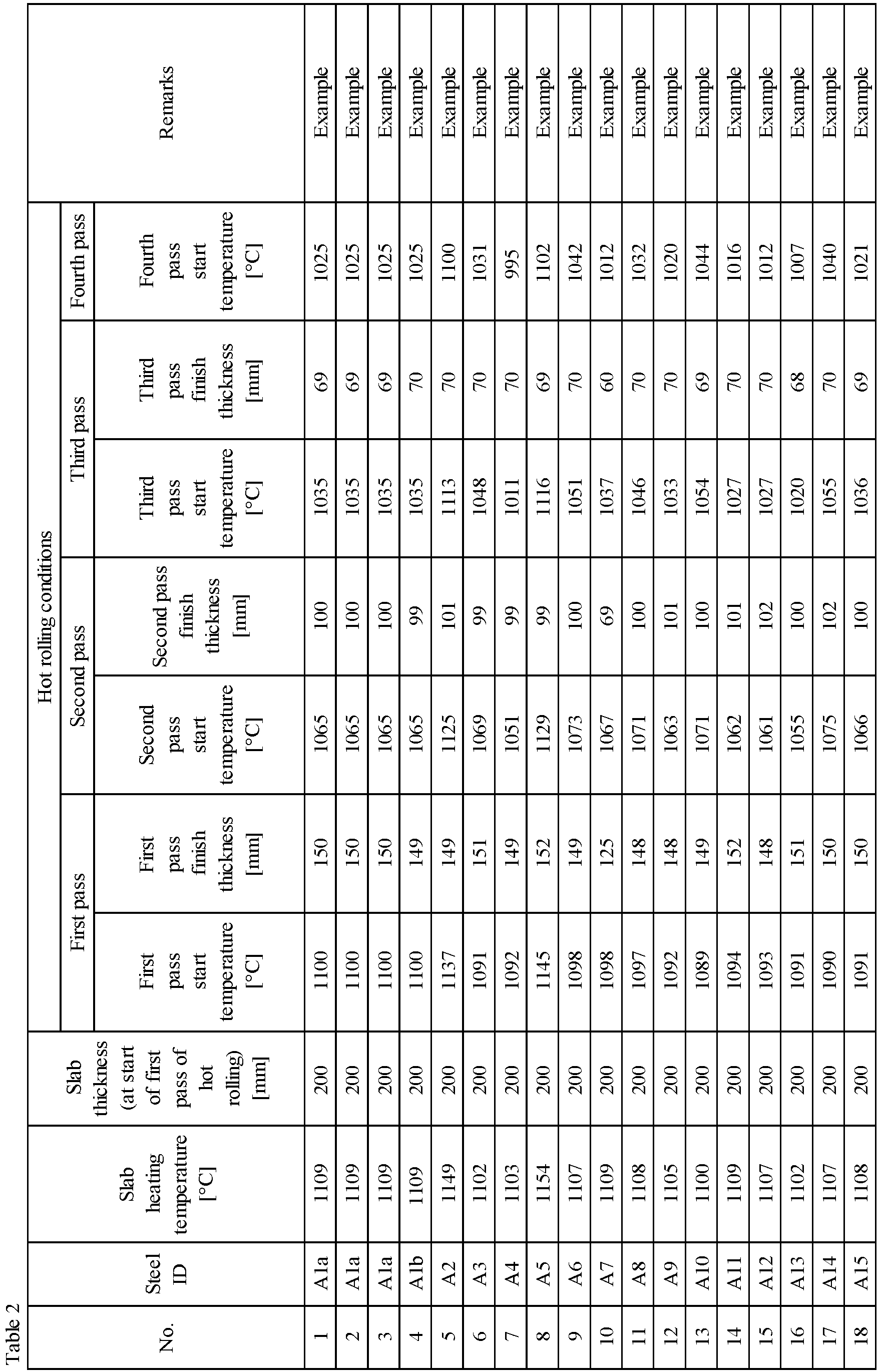


Table 3 No. Steel ID Thickness [mm] Area ratio of crystal grains of 45µm or more [%] Evaluation result Remarks Blanking workability Corrosion resistance 1 Ala 8.0 11 Pass Good Example 2 Ala 8.0 19 Pass Good Example 3 Ala 8.0 12 Pass Good Example 4 Alb 8.2 15 Pass Good Example 5 A2 8.1 6 Pass Good Example 6 A3 8.2 10 Pass Good Example 7 A4 8.1 9 Pass Good Example 8 A5 8.0 4 Pass Good Example 9 A6 8.1 13 Pass Good Example 10 A7 8.0 16 Pass Good Example 11 A8 8.1 1 Pass Good Example 12 A9 8.1 20 Pass Good Example 13 A10 8.2 10 Pass Good Example 14 A11 8.0 11 Pass Excellent Example 15 A12 8.1 5 Pass Excellent Example 16 A13 8.0 17 Pass Good Example 17 A14 8.1 9 Pass Good Example 18 A15 8.1 13 Pass Good Example 19 A16 8.1 13 Pass Good Example 20 Ale 8.1 8 Pass Good Example 21 A1d 8.2 18 Pass Good Example 22 Ale 5.2 10 Pass Good Example 23 A1f 12.9 12 Pass Good Example 24 Alg 8.1 19 Pass Good Example 25 B1 8.1 3 Pass Poor Comparative Example 26 B2 8.2 21 Fail Good Comparative Example 27 B3 8.0 29 Fail Good Comparative Example 28 Alh 8.1 28 Fail Good Comparative Example 29 Ali 8.0 63 Fail Good Comparative Example 30 Alj 8.0 17 Fail Good Comparative Example 31 B4 8.1 25 Fail Good Comparative Example 32 B5 8.1 9 Pass Poor Comparative Example 33 A17 8.0 16 Pass Good Example 34 A18 8.0 15 Pass Good Example 35 A19 8.1 20 Pass Good Example 36 A20 8.0 13 Pass Good Example Underlines indicate outside appropriate range. - As can be seen in Tables 1 to 3, in all Examples, a ferritic stainless steel sheet of 5.0 mm or more in thickness having excellent blanking workability and excellent corrosion resistance was obtained .
- Regarding Comparative Examples, in No. 25, steel B1 whose Cr content was below the appropriate range was used, so that the desired corrosion resistance was not achieved.
- In No. 26, steel B2 whose Ni content was below the appropriate range was used, so that the area ratio of crystal grains of 45 µm or more in grain size was more than 20 % and the desired blanking workability was not achieved.
- In No. 27, steel B3 whose Cr content was above the appropriate range was used, so that the area ratio of crystal grains of 45 µm or more in grain size was more than 20 % and the desired blanking workability was not achieved.
- In No. 28, the cumulative rolling reduction in the temperature range of T1 [°C] to T2 [°C] was below the appropriate range, so that the area ratio of crystal grains of 45 µm or more in grain size was more than 20 % and the desired blanking workability was not achieved.
- In No. 29, the hot-rolled sheet annealing temperature was above the appropriate range, so that the area ratio of crystal grains of 45 µm or more in grain size was more than 20 % and the desired blanking workability was not achieved.
- In No. 30, the coiling temperature in the hot rolling was below the appropriate range, so that a large amount of martensite phase formed and the desired blanking workability was not achieved.
- In No. 31, steel B4 whose Si content was above the appropriate range was used, so that the area ratio of crystal grains of 45 µm or more in grain size was more than 20 % and the desired blanking workability was not achieved.
- In No. 32, steel B5 whose Mn content was above the appropriate range was used, so that MnS forming an initiation point of corrosion precipitated excessively and as a result the predetermined corrosion resistance was not achieved.
- A ferritic stainless steel sheet according to the present disclosure is particularly suitable for use in parts that are thick and are required to have high blanking workability and high corrosion resistance, such as flanges of exhaust system parts of automobiles.
Claims (5)
- A ferritic stainless steel sheet comprising:a chemical composition containing, in mass%,C: 0.001 % to 0.020 %,Si: 0.05 % to 1.00 %,Mn: 0.05 % to 1.50 %,P: 0.04 % or less,S: 0.010 % or less,Al: 0.001 % to 0.300 %,Cr: 10.0 % to 13.0 %,Ni: 0.65 % to 1.50 %,Ti: 0.15 % to 0.35 %, andN: 0.001 % to 0.020 %,with a balance consisting of Fe and inevitable impurities;an area ratio of crystal grains of 45 µm or more in grain size of 20 % or less; anda thickness of 5.0 mm or more.
- The ferritic stainless steel sheet according to claim 1, wherein the chemical composition further contains, in mass%, one or more selected fromCu: 0.01 % to 1.00 %,Mo: 0.01 % to 1.00 %,W: 0.01 % to 0.20 %, andCo: 0.01 % to 0.20 %.
- The ferritic stainless steel sheet according to claim 1 or 2, wherein the chemical composition further contains, in mass%, one or more selected fromV: 0.01 % to 0.20 %,Nb: 0.01 % to 0.10 %, andZr: 0.01 % to 0.20 %.
- The ferritic stainless steel sheet according to any of claims 1 to 3, wherein the chemical composition further contains, in mass%, one or more selected fromB: 0.0002 % to 0.0050 %,REM: 0.001 % to 0.100 %,Mg: 0.0005 % to 0.0030 %,Ca: 0.0003 % to 0.0050 %,Sn: 0.001 % to 0.500 %, andSb: 0.001 % to 0.500 %.
- A method for producing the ferritic stainless steel sheet according to any of claims 1 to 4, the method comprising the following (a) and (b) and optionally comprising the following (c):(a) heating a slab having the chemical composition according to any of claims 1 to 4 to a temperature range of 1050 °C or more and 1250 °C or less;(b) subjecting the slab to hot rolling at a cumulative rolling reduction in a temperature range of T1 [°C] to T2 [°C] of 50 % or more and a coiling temperature of 500 °C or more, to obtain a hot-rolled steel sheet; and(c) subjecting the hot-rolled steel sheet to hot-rolled sheet annealing in a temperature range of 600 °C or more and less than 800 °C,
wherein T1 and T2 are respectively defined by the following formulas (1) and (2):

Applications Claiming Priority (2)
| Application Number | Priority Date | Filing Date | Title |
|---|---|---|---|
| JP2018231929 | 2018-12-11 | ||
| PCT/JP2019/046399 WO2020121817A1 (en) | 2018-12-11 | 2019-11-27 | Ferritic stainless steel sheet and method for producing same |
Publications (2)
| Publication Number | Publication Date |
|---|---|
| EP3896178A1 true EP3896178A1 (en) | 2021-10-20 |
| EP3896178A4 EP3896178A4 (en) | 2022-03-16 |
Family
ID=71076363
Family Applications (1)
| Application Number | Title | Priority Date | Filing Date |
|---|---|---|---|
| EP19896808.3A Pending EP3896178A4 (en) | 2018-12-11 | 2019-11-27 | FERRITIC STAINLESS STEEL SHEET AND METHOD FOR PRODUCTION |
Country Status (8)
| Country | Link |
|---|---|
| US (1) | US12123070B2 (en) |
| EP (1) | EP3896178A4 (en) |
| JP (1) | JP6892011B2 (en) |
| KR (1) | KR20210098525A (en) |
| CN (1) | CN113166831B (en) |
| CA (1) | CA3122753C (en) |
| MX (1) | MX2021006854A (en) |
| WO (1) | WO2020121817A1 (en) |
Cited By (1)
| Publication number | Priority date | Publication date | Assignee | Title |
|---|---|---|---|---|
| EP4613906A4 (en) * | 2022-12-19 | 2026-04-01 | Posco Co Ltd | FERRITIC STAINLESS STEEL WITH IMPROVED IMPACT Toughness AND MANUFACTURING METHOD FOR IT |
Families Citing this family (2)
| Publication number | Priority date | Publication date | Assignee | Title |
|---|---|---|---|---|
| CN115466901B (en) * | 2022-06-15 | 2023-05-26 | 福建青拓特钢技术研究有限公司 | Ultra-pure ferrite stainless steel with low molybdenum and no sigma phase precipitation for ball pen head and production method thereof |
| EP4652414A1 (en) * | 2023-01-20 | 2025-11-26 | voestalpine Metal Forming GmbH | Holding element and assembly comprising multiple holding elements for at least one solar element |
Family Cites Families (18)
| Publication number | Priority date | Publication date | Assignee | Title |
|---|---|---|---|---|
| US365073A (en) * | 1887-06-21 | Cotton-cultivator | ||
| US3650731A (en) * | 1969-01-31 | 1972-03-21 | Allegheny Ludlum Steel | Ferritic stainless steel |
| JP3839953B2 (en) * | 1998-04-17 | 2006-11-01 | 新日本製鐵株式会社 | Manufacturing method of stainless steel strip for building structure |
| US7985372B2 (en) | 2005-06-09 | 2011-07-26 | Jfe Steel Corporation | Ferritic stainless steel sheet for use in raw material pipe for forming bellows pipe |
| JP4752620B2 (en) * | 2005-06-09 | 2011-08-17 | Jfeスチール株式会社 | Ferritic stainless steel sheet for bellows tube |
| EP2182085B1 (en) * | 2007-08-20 | 2017-10-11 | JFE Steel Corporation | Ferritic stainless steel plate excellent in punchability and process for production of the same |
| JP5682901B2 (en) * | 2008-09-18 | 2015-03-11 | Jfeスチール株式会社 | Ti-added ferritic stainless steel sheet excellent in spinning workability and manufacturing method thereof |
| CN102260833B (en) * | 2010-05-25 | 2013-12-11 | 宝山钢铁股份有限公司 | Stainless steel for high-performance B4003M truck |
| CN102534425A (en) * | 2012-01-29 | 2012-07-04 | 宝山钢铁股份有限公司 | Low-cost high-strength ferritic stainless steel and manufacturing method thereof |
| JP5884183B2 (en) * | 2013-03-28 | 2016-03-15 | Jfeスチール株式会社 | Structural stainless steel sheet |
| JP6179485B2 (en) * | 2014-08-14 | 2017-08-16 | Jfeスチール株式会社 | Ferritic stainless steel sheet |
| KR101940427B1 (en) * | 2014-08-14 | 2019-01-18 | 제이에프이 스틸 가부시키가이샤 | Ferritic stainless steel sheet |
| JP6791646B2 (en) | 2015-03-30 | 2020-11-25 | 日鉄ステンレス株式会社 | Stainless steel sheet with excellent toughness and its manufacturing method |
| WO2017013850A1 (en) | 2015-07-17 | 2017-01-26 | Jfeスチール株式会社 | Ferrite-based hot-rolled stainless steel sheet, hot-rolled annealed sheet, and method for manufacturing said sheets |
| JP6022097B1 (en) | 2016-03-30 | 2016-11-09 | 日新製鋼株式会社 | Ti-containing ferritic stainless steel sheet and manufacturing method |
| KR20180126064A (en) * | 2016-03-30 | 2018-11-26 | 닛신 세이코 가부시키가이샤 | Nb-containing ferritic stainless steel sheet and manufacturing method thereof |
| CN110366601B (en) * | 2017-02-28 | 2021-10-22 | 日本制铁株式会社 | Ferritic stainless steel sheets, hot rolled coils and flange components for automotive exhaust systems |
| ES2924685T3 (en) | 2017-04-27 | 2022-10-10 | Jfe Steel Corp | Annealed hot-rolled ferritic stainless steel sheet and method of making the same |
-
2019
- 2019-11-27 JP JP2020517406A patent/JP6892011B2/en active Active
- 2019-11-27 CA CA3122753A patent/CA3122753C/en active Active
- 2019-11-27 CN CN201980081620.3A patent/CN113166831B/en active Active
- 2019-11-27 EP EP19896808.3A patent/EP3896178A4/en active Pending
- 2019-11-27 MX MX2021006854A patent/MX2021006854A/en unknown
- 2019-11-27 US US17/299,308 patent/US12123070B2/en active Active
- 2019-11-27 WO PCT/JP2019/046399 patent/WO2020121817A1/en not_active Ceased
- 2019-11-27 KR KR1020217021082A patent/KR20210098525A/en not_active Ceased
Cited By (1)
| Publication number | Priority date | Publication date | Assignee | Title |
|---|---|---|---|---|
| EP4613906A4 (en) * | 2022-12-19 | 2026-04-01 | Posco Co Ltd | FERRITIC STAINLESS STEEL WITH IMPROVED IMPACT Toughness AND MANUFACTURING METHOD FOR IT |
Also Published As
| Publication number | Publication date |
|---|---|
| CA3122753A1 (en) | 2020-06-18 |
| MX2021006854A (en) | 2021-07-02 |
| JP6892011B2 (en) | 2021-06-18 |
| WO2020121817A1 (en) | 2020-06-18 |
| CN113166831A (en) | 2021-07-23 |
| CA3122753C (en) | 2023-07-04 |
| CN113166831B (en) | 2022-11-01 |
| KR20210098525A (en) | 2021-08-10 |
| JPWO2020121817A1 (en) | 2021-02-15 |
| US20220017984A1 (en) | 2022-01-20 |
| EP3896178A4 (en) | 2022-03-16 |
| US12123070B2 (en) | 2024-10-22 |
Similar Documents
| Publication | Publication Date | Title |
|---|---|---|
| EP3399062B1 (en) | High-strength steel sheet, high-strength galvanized steel sheet, and method for manufacturing same | |
| EP3124635B1 (en) | Rolled ferritic stainless steel sheet, method for producing the same, and flange part | |
| EP3553195B1 (en) | High mn steel sheet and method for producing same | |
| EP3178955B1 (en) | High-strength steel sheet and production method for same, and production method for high-strength galvanized steel sheet | |
| EP3395974B1 (en) | High-strength steel sheet and method for manufacturing the same | |
| EP3828296B1 (en) | High-strength steel plate and method for producing same | |
| EP3018230B1 (en) | Cold-rolled steel sheet, galvanized cold-rolled steel sheet, and method for manufacturing the same | |
| EP3530769B1 (en) | Martensitic stainless steel sheet | |
| EP3118342B1 (en) | Ferritic stainless steel | |
| KR20190034600A (en) | Steel sheet and manufacturing method thereof | |
| EP3342893A1 (en) | Alloying molten zinc-plated steel sheet and manufacturing method therefor | |
| KR20180019736A (en) | High-strength hot-rolled steel sheet | |
| US12473623B2 (en) | Steel sheet | |
| EP3666917B1 (en) | Ferritic stainless-steel sheet and method for manufacturing same | |
| EP3093362B1 (en) | Ferritic stainless steel and method for producing same | |
| EP3587610B1 (en) | Hot-rolled and annealed ferritic stainless steel sheet, and method for manufacturing same | |
| EP3677700A1 (en) | High-mn steel and production method therefor | |
| US12123070B2 (en) | Ferritic stainless steel sheet and method for producing same | |
| EP4613899A1 (en) | Galvanized steel sheet and member, and method for producing same | |
| EP4249621A1 (en) | Steel material and method for producing same, and tank and method for producing same | |
| CA3114743C (en) | Hot-rolled and annealed ferritic stainless steel sheet and method for producing the same | |
| JP2023085560A (en) | Duplex stainless steel and manufacturing method thereof | |
| EP4509628A1 (en) | Ferritic stainless steel and production method therefor | |
| JP2025014954A (en) | Hot-rolled and annealed ferritic stainless steel sheet and method for producing the same | |
| EP4685260A1 (en) | High-strength steel sheet and method for producing same |
Legal Events
| Date | Code | Title | Description |
|---|---|---|---|
| STAA | Information on the status of an ep patent application or granted ep patent |
Free format text: STATUS: THE INTERNATIONAL PUBLICATION HAS BEEN MADE |
|
| PUAI | Public reference made under article 153(3) epc to a published international application that has entered the european phase |
Free format text: ORIGINAL CODE: 0009012 |
|
| STAA | Information on the status of an ep patent application or granted ep patent |
Free format text: STATUS: REQUEST FOR EXAMINATION WAS MADE |
|
| 17P | Request for examination filed |
Effective date: 20210708 |
|
| AK | Designated contracting states |
Kind code of ref document: A1 Designated state(s): AL AT BE BG CH CY CZ DE DK EE ES FI FR GB GR HR HU IE IS IT LI LT LU LV MC MK MT NL NO PL PT RO RS SE SI SK SM TR |
|
| A4 | Supplementary search report drawn up and despatched |
Effective date: 20220215 |
|
| RIC1 | Information provided on ipc code assigned before grant |
Ipc: C21D 1/26 20060101ALI20220209BHEP Ipc: C21D 6/00 20060101ALI20220209BHEP Ipc: C21D 8/02 20060101ALI20220209BHEP Ipc: C21D 9/46 20060101ALI20220209BHEP Ipc: C22C 38/60 20060101ALI20220209BHEP Ipc: C22C 38/54 20060101ALI20220209BHEP Ipc: C22C 38/52 20060101ALI20220209BHEP Ipc: C22C 38/48 20060101ALI20220209BHEP Ipc: C22C 38/46 20060101ALI20220209BHEP Ipc: C22C 38/42 20060101ALI20220209BHEP Ipc: C22C 38/44 20060101ALI20220209BHEP Ipc: C22C 38/06 20060101ALI20220209BHEP Ipc: C22C 38/04 20060101ALI20220209BHEP Ipc: C22C 38/02 20060101ALI20220209BHEP Ipc: C22C 38/00 20060101ALI20220209BHEP Ipc: C22C 38/50 20060101AFI20220209BHEP |
|
| DAV | Request for validation of the european patent (deleted) | ||
| DAX | Request for extension of the european patent (deleted) | ||
| RIN1 | Information on inventor provided before grant (corrected) |
Inventor name: FUJISAWA, MITSUYUKI Inventor name: YOSHINO, MASATAKA Inventor name: KAWABE, HIDETAKA Inventor name: INOUE, KEISHI |