EP3896016A1 - Tablet cassette rotor and tablet cassette - Google Patents
Tablet cassette rotor and tablet cassette Download PDFInfo
- Publication number
- EP3896016A1 EP3896016A1 EP19896703.6A EP19896703A EP3896016A1 EP 3896016 A1 EP3896016 A1 EP 3896016A1 EP 19896703 A EP19896703 A EP 19896703A EP 3896016 A1 EP3896016 A1 EP 3896016A1
- Authority
- EP
- European Patent Office
- Prior art keywords
- tablet
- rotor
- supporting
- supporting pedestal
- cassette body
- Prior art date
- Legal status (The legal status is an assumption and is not a legal conclusion. Google has not performed a legal analysis and makes no representation as to the accuracy of the status listed.)
- Pending
Links
- NJPPVKZQTLUDBO-UHFFFAOYSA-N novaluron Chemical compound C1=C(Cl)C(OC(F)(F)C(OC(F)(F)F)F)=CC=C1NC(=O)NC(=O)C1=C(F)C=CC=C1F NJPPVKZQTLUDBO-UHFFFAOYSA-N 0.000 claims abstract description 90
- 238000007599 discharging Methods 0.000 claims abstract description 26
- 239000003826 tablet Substances 0.000 description 262
- 230000002093 peripheral effect Effects 0.000 description 12
- 238000000926 separation method Methods 0.000 description 4
- 230000001154 acute effect Effects 0.000 description 2
- 230000008094 contradictory effect Effects 0.000 description 2
- 239000002775 capsule Substances 0.000 description 1
- 239000007947 dispensing tablet Substances 0.000 description 1
- 239000008298 dragée Substances 0.000 description 1
- 230000000694 effects Effects 0.000 description 1
- 230000002452 interceptive effect Effects 0.000 description 1
- 238000005360 mashing Methods 0.000 description 1
- 239000007940 sugar coated tablet Substances 0.000 description 1
- 238000011144 upstream manufacturing Methods 0.000 description 1
Images








Classifications
-
- B—PERFORMING OPERATIONS; TRANSPORTING
- B65—CONVEYING; PACKING; STORING; HANDLING THIN OR FILAMENTARY MATERIAL
- B65G—TRANSPORT OR STORAGE DEVICES, e.g. CONVEYORS FOR LOADING OR TIPPING, SHOP CONVEYOR SYSTEMS OR PNEUMATIC TUBE CONVEYORS
- B65G47/00—Article or material-handling devices associated with conveyors; Methods employing such devices
- B65G47/02—Devices for feeding articles or materials to conveyors
- B65G47/04—Devices for feeding articles or materials to conveyors for feeding articles
- B65G47/12—Devices for feeding articles or materials to conveyors for feeding articles from disorderly-arranged article piles or from loose assemblages of articles
- B65G47/14—Devices for feeding articles or materials to conveyors for feeding articles from disorderly-arranged article piles or from loose assemblages of articles arranging or orientating the articles by mechanical or pneumatic means during feeding
-
- G—PHYSICS
- G07—CHECKING-DEVICES
- G07F—COIN-FREED OR LIKE APPARATUS
- G07F17/00—Coin-freed apparatus for hiring articles; Coin-freed facilities or services
- G07F17/0092—Coin-freed apparatus for hiring articles; Coin-freed facilities or services for assembling and dispensing of pharmaceutical articles
-
- A—HUMAN NECESSITIES
- A61—MEDICAL OR VETERINARY SCIENCE; HYGIENE
- A61J—CONTAINERS SPECIALLY ADAPTED FOR MEDICAL OR PHARMACEUTICAL PURPOSES; DEVICES OR METHODS SPECIALLY ADAPTED FOR BRINGING PHARMACEUTICAL PRODUCTS INTO PARTICULAR PHYSICAL OR ADMINISTERING FORMS; DEVICES FOR ADMINISTERING FOOD OR MEDICINES ORALLY; BABY COMFORTERS; DEVICES FOR RECEIVING SPITTLE
- A61J3/00—Devices or methods specially adapted for bringing pharmaceutical products into particular physical or administering forms
-
- A—HUMAN NECESSITIES
- A61—MEDICAL OR VETERINARY SCIENCE; HYGIENE
- A61J—CONTAINERS SPECIALLY ADAPTED FOR MEDICAL OR PHARMACEUTICAL PURPOSES; DEVICES OR METHODS SPECIALLY ADAPTED FOR BRINGING PHARMACEUTICAL PRODUCTS INTO PARTICULAR PHYSICAL OR ADMINISTERING FORMS; DEVICES FOR ADMINISTERING FOOD OR MEDICINES ORALLY; BABY COMFORTERS; DEVICES FOR RECEIVING SPITTLE
- A61J7/00—Devices for administering medicines orally, e.g. spoons; Pill counting devices; Arrangements for time indication or reminder for taking medicine
- A61J7/0076—Medicament distribution means
-
- B—PERFORMING OPERATIONS; TRANSPORTING
- B65—CONVEYING; PACKING; STORING; HANDLING THIN OR FILAMENTARY MATERIAL
- B65G—TRANSPORT OR STORAGE DEVICES, e.g. CONVEYORS FOR LOADING OR TIPPING, SHOP CONVEYOR SYSTEMS OR PNEUMATIC TUBE CONVEYORS
- B65G65/00—Loading or unloading
- B65G65/30—Methods or devices for filling or emptying bunkers, hoppers, tanks, or like containers, of interest apart from their use in particular chemical or physical processes or their application in particular machines, e.g. not covered by a single other subclass
- B65G65/34—Emptying devices
- B65G65/40—Devices for emptying otherwise than from the top
- B65G65/48—Devices for emptying otherwise than from the top using other rotating means, e.g. rotating pressure sluices in pneumatic systems
- B65G65/4809—Devices for emptying otherwise than from the top using other rotating means, e.g. rotating pressure sluices in pneumatic systems rotating about a substantially vertical axis
-
- A—HUMAN NECESSITIES
- A61—MEDICAL OR VETERINARY SCIENCE; HYGIENE
- A61J—CONTAINERS SPECIALLY ADAPTED FOR MEDICAL OR PHARMACEUTICAL PURPOSES; DEVICES OR METHODS SPECIALLY ADAPTED FOR BRINGING PHARMACEUTICAL PRODUCTS INTO PARTICULAR PHYSICAL OR ADMINISTERING FORMS; DEVICES FOR ADMINISTERING FOOD OR MEDICINES ORALLY; BABY COMFORTERS; DEVICES FOR RECEIVING SPITTLE
- A61J7/00—Devices for administering medicines orally, e.g. spoons; Pill counting devices; Arrangements for time indication or reminder for taking medicine
- A61J7/0076—Medicament distribution means
- A61J7/0084—Medicament distribution means for multiple medicaments
-
- B—PERFORMING OPERATIONS; TRANSPORTING
- B65—CONVEYING; PACKING; STORING; HANDLING THIN OR FILAMENTARY MATERIAL
- B65G—TRANSPORT OR STORAGE DEVICES, e.g. CONVEYORS FOR LOADING OR TIPPING, SHOP CONVEYOR SYSTEMS OR PNEUMATIC TUBE CONVEYORS
- B65G2201/00—Indexing codes relating to handling devices, e.g. conveyors, characterised by the type of product or load being conveyed or handled
- B65G2201/02—Articles
- B65G2201/027—Tablets, capsules, pills or the like
-
- B—PERFORMING OPERATIONS; TRANSPORTING
- B65—CONVEYING; PACKING; STORING; HANDLING THIN OR FILAMENTARY MATERIAL
- B65G—TRANSPORT OR STORAGE DEVICES, e.g. CONVEYORS FOR LOADING OR TIPPING, SHOP CONVEYOR SYSTEMS OR PNEUMATIC TUBE CONVEYORS
- B65G65/00—Loading or unloading
- B65G65/30—Methods or devices for filling or emptying bunkers, hoppers, tanks, or like containers, of interest apart from their use in particular chemical or physical processes or their application in particular machines, e.g. not covered by a single other subclass
Definitions
- the present invention relates to a rotor and a tablet cassette utilizing the rotor and the tablet cassette being disposed to a tablet storage/dispensation apparatus that stores a plurality of tablets and dispenses the tablets by required number according to a prescription.
- a tablet storage/dispensation apparatus placed at ethical pharmacies and hospitals can provide automatically tablets depending on prescriptions to many patients quickly, certainly, and safely.
- the tablet storage/dispensation apparatus is desired to enable dispensation of tablets in many kinds as much as possible.
- the tablet storage/dispensation apparatus has many tablet cassettes being capable of storing and dispensing tablets in different kinds.
- Each of the tablet cassettes is equipped with a cassette body storing tablets and a rotor disposed rotatably and drivably at the bottom of a cassette body.
- the tablets in the cassette body are guided in turn to a plurality of tablet guiding paths formed to the rotor, and at the time when each of the tablet guiding paths is aligned to a tablet discharging hole, the tablet at the bottom in the tablet guiding path is separated from the just upper tablet by a separating member such that only the bottom tablet is discharged from the tablet discharging hole.
- Patent Literature 1 depending on sizes, shapes, kinds of tablets, the rotor of the tablet cassette that is able to change a width and a depth of the tablet guiding path and a height from a tablet supporting pedestal disposed at the bottom of the tablet guiding path to the separating member.
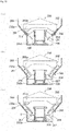
- a face at the rotor side along the depth direction of the tablet guiding path 201 formed to the rotor 200 of Patent Literature 1 is defined by a slanted outer face 202a of an elevatable rotor body 202 and is inclined to a rotation shaft of the rotor 200 while opposing to a slanted inner face 203a having a reversed-cone shape of the cassette body 203.
- the tablet supporting pedestal 204 is disposed at the top of the arm 207 formed to the elevatable member 206 which is screwed to the outer-peripheral screw part of cylindrical rotation part 205.
- a distance between the slanted inner face 203 of the cassette body 203 and the slanted outer face 202a of the rotor body 202 changes so that the depth of the tablet guiding path 201 may be adjusted depending on the thickness of tablets.
- an elevatable member 206 goes up and down and according to this, the tablet supporting pedestal 204 moves toward the rotation shaft of rotor 200 such that a distance between the tablet supporting pedestal 204 and the separating member 208 may be adjusted depending on the height of tablets.
- the bottom part of the cassette body 203 is formed to a cylindrical face 203b for allowing the arm of the elevatable member 206 to elevate along the rotation shaft of rotor 200.
- a space S between an upper face of the tablet supporting pedestal 204 and the cylindrical face 203b of the cassette body 203 becomes increased.
- the top part of the tablet becomes mismatch with the position of the separating member 208 and the second tablet clogs by interfering with the separating member 208 to disturb the rotation of the rotor 200.
- Patent Literature 1 Japanese Patent No. 6222414
- the present invention has been completed considering the above conventional problem and the present invention aims to provide a rotor for a cassette and a tablet cassette which are able to prevent tablets from clogging in the tablet guiding path regardless of the elevation position of the tablet supporting pedestal.
- the present invention is configured such that a rotor received rotatably in a cassette body for receiving tablets comprises a tablet guiding path formed between a slanted inner face of the cassette body and a slanted outer face of the rotor for guiding the tablets received in the cassette body to a tablet discharging hole disposed to the cassette body, a separating member disposed above the tablet discharging hole of the cassette body for separating a space between a tablet at a bottom position and a tablet at an upper position, a tablet supporting pedestal disposed elevatably to the tablet guiding path for supporting the tablet at the bottom position in the tablet guiding path, and a height adjustment mechanism for adjusting a tablet discharging height between the tablet supporting pedestal and the separating member, and the height adjustment mechanism makes the tablet supporting pedestal elevate to a direction inclined to a rotation shaft of the rotor along the tablet guiding path.
- the space between the upper face of tablet supporting pedestal and the inner face of cassette body does not increase.
- the tablet can be prevented from clogging in the tablet guiding path independent of the elevation position of tablet supporting pedestal.
- the height adjustment mechanism preferably comprises a rotatable rotation member formed with a spiral guide at an outer circumferential face for engaging with the tablet supporting pedestal, a supporting member for preventing movement of the tablet supporting pedestal along the spiral guide by supporting the tablet supporting pedestal from both sides, and a height adjustment member for making the tablet supporting pedestal engaging with the spiral guide elevate to a direction inclined to a rotation shaft of the rotor.
- the rotation member preferably includes a reversed cone-shaped outer circumferential face.
- the supporting member preferably comprises a reversed cone-shape covering an outer side of the rotation member and is formed with a slit for allowing the tablet supporting pedestal to protrude and the slit extends along the tablet guiding path to support the tablet supporting pedestal from both sides.
- the height adjustment member preferably comprises a driving gear meshing with a driven gear formed at an inner circumferential face of the rotation member and is externally operatable.
- the rotor preferably comprises a lower base, an operation base, and an upper base, and the supporting member is fixed to the lower base, the operation base is fixed to the supporting base, and the upper base is fixed to the operation base.
- the height adjustment mechanism preferably comprises a first rotation member, a plurality of second rotation members synchronously rotating with the first rotation member and being formed with a male screw to which the tablet supporting pedestal is screwed, a supporting member for preventing the tablet supporting pedestal from rotating about the second rotation member by supporting the tablet supporting pedestal from both sides, a height adjustment member for making the first rotation member rotate and making the second rotation shaft member rotate through the first rotation member so as to make the tablet supporting pedestal elevate to a direction inclined to a rotation shaft of the rotor.
- the present invention is configured such that a rotor received rotatably in a cassette body for receiving tablets comprises a tablet guiding path formed between a slanted inner face of the cassette body and a slanted outer face of the rotor for guiding the tablets received in the cassette body to a tablet discharging hole disposed to the cassette body, a separating member disposed above the tablet discharging hole of the cassette body for separating a space between a tablet at a bottom position and a tablet at an upper position, a tablet supporting pedestal disposed elevatably to the tablet guiding path for supporting the tablet at the bottom position in the tablet guiding path, and a height adjustment mechanism for adjusting a tablet discharging height between the tablet supporting pedestal and the separating member, and the height adjustment mechanism makes the tablet supporting pedestal elevate with keeping a protrusion amount from the slanted outer face constant independent of an elevation position of the tablet supporting pedestal.
- a space between an upper face of the tablet supporting pedestal and an inner face of the cassette body does not increase so that clogging of tablets within the tablet guiding path may be prevented.
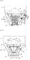
- Fig. 1 shows a tablet cassette 1 equipped to a tablet storage/dispensation apparatus.
- the tablet cassette 1 includes a cassette body 3 disposed on a motor base 2 and a rotor 4 of the present invention received in the cassette body 3.
- the cassette body 3, as shown in Fig. 2 is configured from a tablet storage part 5 being capable of storing many tablets T and a rotor receiver part 6 disposed beneath the tablet storage part 5 for receiving the rotor 4.
- An upper end of the tablet storage part 5 is opened and is allowed to be opened and closed with a cover not illustrated.
- the rotor receiver part 6 includes an upper slanted inner face 6a having a revered-cone shape, a lower vertical inner face 6b having a cylindrical shape, and a bottom face 6c.
- a tablet discharging hole 7 is formed at the bottom part of the upper slanted inner face 6a.
- the tablet discharging hole 7 is connected to a tablet discharge path 2a formed to the base 2.
- a separating member 8 is disposed and a top of a separating member 8 is inserted into the inside from the outside of the rotor receiver part 6 through the upper part of the tablet discharging hole 7.
- a rotor shaft hole 9 is formed at the center of the bottom face 6c.
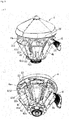
- the rotor 4 as shown in Fig. 3 , has a shape having a cone-shaped upper face, a reversed-cone shaped lateral face, and a plane bottom face.
- a tablet pocket 4a extending circumferentially is disposed, and a plurality of tablet guiding paths 4b (in the embodiment six) extending downwardly from the tablet pocket 4a are disposed circumferentially in even spacings.
- the tablet pocket 4a is formed by an outer peripheral face of the elevator member 20, a first horizontal protrusion piece 61d of the first movable member 61, and a horizontal protrusion piece 62f of a second movable member 62 each of which will be explained later, and the tablet pocket 4a is enclosed by the upper slanted inner face 6a of the cassette body 3 to receive and to align the tablet T of the tablet storage part 5.
- the tablet guiding path 4b is formed between the upper slanted inner face 6a of the cassette body 3 and the slanted outer face 22a of the downward protrusion part 22 formed to the elevator member 20 which will be explained later. Furthermore, the tablet guiding path 4b includes a first vertical protrusion piece 61c of a first movable member 61 described later, a second vertical protrusion piece 62c of a second movable member 62 described later, and a tablet supporting pedestal 53 described later to receive and to guide the tablet T aligned in the tablet pocket 4a.
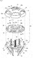
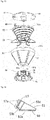
- Fig. 4 shows a rotor 4 in an exploded state.
- the rotor 4 includes a rotor cover 10, an elevator member 20, an upper base 30, an operation part 40, a height adjustment part 50, a width adjustment part 60, and a lower base 70, thereby, as described hereunder, a depth adjustment mechanism, a height adjustment mechanism and a width adjustment mechanism are configured such that depending on the thickness, the height, and the width of the tablet received in the tablet receiver part 5, the depth ,the height, and the width of the tablet guiding path 4b may be adjusted.
- Fig. 5 shows a whole view of a depth adjustment mechanism
- Fig. 6 and Fig. 7 show members configuring the depth adjustment mechanism.
- the depth adjustment mechanism is configured from a rotor cover 10, an elevator member 20, an upper base 30, and a depth adjustment member 80 of the operation part 40.
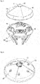
- the rotor cover 10 has, as shown in Fig. 5 and Fig. 6 , generally an umbrella shape.
- the upper face of the rotor cover 10 is formed as a cone shape and its outer peripheral face is formed as a cone shape having more acute inclination than that of the upper face.
- a cap 12 is detachably attached to a cap attachment hole 11 disposed at the center of the upper face of the rotor cover.
- an engagement piece 13 is disposed at the edge of the cap attachment hole 11 such that the engagement piece 13 can engage with the engagement hole 24 of the elevator member 20 shown in Fig. 7 to make the rotor cover 10 detachable to the elevator member 20.
- a plurality of steps 14 is formed circumferentially, and by these steps 14, the tablets stored in the cassette body 3 with respect to the rotation of rotor 4 can be mixed.
- protrusions 15 are formed at six evenly distributed positions, and the protrusions 15 engage with the notchs 25 of the elevator member 20 shown in Fig. 7 such that the rotor cover 10 does not rotate relatively to the elevator member 20.
- the elevator member 20 includes as shown in Fig. 7 a base part 21 and protrusion parts 22 extending downward.
- a base 21 includes, as shown in Fig. 7 and Fig. 8 , for making it possible to enshroud the rotor cover 10, a cone-shaped upper face 21a, an outer peripheral face 21b having a cone shape with more acute inclination than that of the upper face 21a, an outer peripheral edge 21c extending downward from six evenly distributed positions at the bottom end of the outer peripheral face 21b.
- a shaft part 23 protruding up-and-down is disposed at the center thereof, and a screw hole 23a is formed within which the male screw part 81 of a depth adjustment member 80 described later is screwed.
- the downward extending protrusion part 22 is, as shown in Fig. 7 , fixed by a fixing screw 22c between adjacent outer peripheral edges of the base part 21.
- the downward extending protrusion part 22 extends inward and downward and includes a slanted outer face 22a and a slanted inner face 22b.
- the slanted outer face 22a of the downward extending protrusion part 22 forms a continuous face to the outer peripheral edge 21c of the base part 21 and forms a bottom face of the tablet guiding path 4b.
- a slide part 28 is disposed at the upper part of the slanted inner face 22b.
- An upper end of the slide part 28 is supported by a supporting hole 27 of the base 21.
- a slit 29 is formed for allowing the tablet supporting pedestal 53 to protrude from the inside.
- the elevator member 20 by engaging the slide part 28 with the guide member 36 of the upper base, rotates elevatably to an upper base 30 and integrally with the upper base 30.
- the upper base 30 includes, as shown in Fig. 7 and Fig. 9 , a circular base part 31 and an outer peripheral edge 32.
- a notch parts 35 are formed at circumferential six evenly distributed positions of the outer peripheral edge of the upper base 30 and to the notch parts 35, guide parts 36 each having a U-shaped cross section are formed for guiding the slide part 28 of the downward extending protrusion part 22.
- the upper base 30 is fixed to an operation base 41 of an operation part 40 by a fixing screw 37.
- the operation part 40 is, as shown in Fig. 4 , one that the depth adjustment part 80, the height adjustment part 90, and the width adjustment part 100 are assembled.
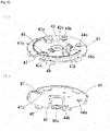
- the operation base 41 has, as shown in Fig. 10 , a circular shape and to the center of the upper face, a concave part 42 for supporting a lower end of the depth adjustment member 80 is formed and a screw passing-through hole 42a is formed at the center of a concave part 42. Furthermore, at the upper face of the operation base 41, attachment seats 43a, 43b for upper base 30, two holes 44 for supporting the width adjustment member 100, and stopper attachment seats 45a, 45b are formed. Furthermore, at an upper face of the operation base 41, a guide 46 having an arch shape with which an inner peripheral edge of a first supporting member 63 of the width adjustment part 60 engages.
- a notch 47 is formed and an engagement part 47a to which the depth adjustment member 80 engages is formed at an inner side of the notch 47.
- a columnar protrusion 48 is formed and at a lower end of the protrusion 48, a rectangular engagement hole 48a with which an engagement protrusion part 54a of a supporting shaft 54 of a supporting member 51 formed to the height adjustment part 50 engages.
- engagement pieces 49 are formed at circumferential six evenly distributed positions.
- the operation base 41 is attached integrally with the supporting member 51 by engaging the engagement piece 49 with an engagement concave part 51c of the supporting member 51 formed to the height adjustment part 50 shown in Fig. 12 .
- the depth adjustment member 80 of the operation part 40 includes, as shown in Fig. 7 , a male screw part 81 and a gear part 82 at the lower end.
- the male screw part 81 screws into a screw hole 23 of the elevator member 20, and the gear part 82 at the lower end is received and supported in a concave part 42 of the operation base 41; the upper end of the male screw part 81 protrudes to expose from the screw hole 23a of the elevator member 20 for allowing adjustment by rotation from the outside.
- a top of a stopper 83 formed of an elastic piece engages.
- the gear part 82 at the lower end of the depth adjustment member 80 is formed larger than the hole 23 of the upper base 30 such that the depth adjustment member 80 does not escape upward from the upper base 30.
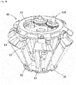
- Fig. 11 shows a whole view of a height adjustment mechanism
- Fig. 12 shows members configuring the height adjustment mechanism.
- the height adjustment mechanism is configured by a lower base 70, a supporting member 51, a rotation member 52, and six tablet supporting pedestal 53, and a height adjustment member 90.
- the lower base 70 is configured as shown in Figs. 12 , 13 by an annular lower plate 71, a circular upper plate 72, five leg parts 73 disposed at circumferential five evenly distributed positions connecting the inner periphery of an inner circumferential edge of the lower plate 71 and the outer circumferential edge of the upper plate 72, and libs 74 disposed both lateral edges of each of the leg parts 73.
- a screw inserting hole 75 and three holes around the screw inserting hole 76 for engaging the convex parts 51b of the supporting member 51 are formed.
- a driving shaft not shown disposed at the bottom of the cassette body 3 engages.
- the supporting member 51 has a shape of the container which has a reversed-cone shape and opens upward.
- a supporting shaft 54 for supporting rotatably a rotation member 52 is disposed protrudingly and upwardly.
- a quadrilateral engagement protrusion 54a with which an engagement part 48a of the operation base 41 engages and a screw hole 54b are formed.
- a screw hole 51a and three convex parts 51b about it are formed.
- slits 55 are formed radially at six circumferentially evenly distributed positions and guides 55a are defined inside both lateral edges of each slits 55.
- engagement concave parts 51c are foemed.
- the supporting member 51 is placed on the upper plate of the lower base 70, with making the convex parts 51b engage with the holes 76, and is fixed and attached to the lower base 70 by a fixing screw 59a through a magnet plate 59c.
- the rotation member 52 has a cylinder shape which has a reversed-cone shape received with the supporting member 51 and opens upward and downward.
- a cylinder-shaped shaft part 56 is supportingly disposed to the inner face of the rotation member 52 though the libs 56a.
- a spiral guide 52a having a spiral screw shape is formed.
- a driven gear 52b is formed at the inner face and at the upper end of rotation member 52.
- Each of the six tablet supporting pedestals 53 includes, as shown in Fig. 14 , a bottom line 53a, a first hypotenuse 53b, and a second hypotenuse 53c, and has the plate shape of a near rigid angled triangle where the first hypotenuse 53b and the second hypotenuse 53c form the right angle.
- a fixing base 57 is disposed, and to the fixing base 57, columnar two engagement protrusions 57a engaging with the recess of the spiral guide 52a are disposed.
- the second hypotenuse 53c is positioned at the lower part of the tablet guiding path 4b and supports the tablet at the bottom position in the tablet guiding path 4b.
- the second hypotenuse 53c is a face becoming a measure of the height between the tablet supporting pedestal 53 and the separating member 8 and all the second hypotenuses 53 of six tablet supporting pedestals 53 become the same height each other.
- the height adjustment member 90 is attached, as shown in Fig. 12 , to an engagement part 47a of a notch 47 formed to the operation base 41 of the operation part 40 and has at the lower end a driving gear 91 meshing with the driven gear 52b of rotation member 52.
- the top of the height adjustment member 90 protrudes and is exposed adjustably and externally from the hole 26 of the upper face of the base part 21 formed to the elevator member 20.
- the rotation part 52 is received in the supporting member 51 under the condition where the six tablet supporting pedestals 53 are engaged.
- the opening of the supporting member 51 is covered with the operation base 41.
- the operation base 41 is fixed and is attached to the supporting member 51 by engaging the engagement piece 49 with the engagement concave part 51c of the supporting member 51, fitting the engagement hole 48a of the protrusion part 48 to the engagement protrusion part 54a of a supporting shaft 54 disposed to the supporting member 51, and screwing the fixing screw 59b to the screw hole 54b of the supporting shaft 54 disposed to the supporting member 51.
- the fixing base 57 of the tablet supporting pedestal 53 is supported by guides 55a of the supporting member 51 from both sides, and the tablet supporting pedestal 53 is fitted slidably into the slit 55 of the supporting member 51. Thereby, the tablet supporting pedestal 53 can support the tablet at the bottom position in the tablet guiding path 4b.
- the position of a spiral guide 52a formed to the rotation member 52 is defined in the configuration where the top of the tablet supporting pedestal 53 is placed at the lower end of the upper slanted inner face 6a in the cassette body 3.
- Fig. 16 shows a whole view of the width adjustment mechanism
- Fig. 17 shows members configuring the width adjustment mechanism.
- the width adjustment mechanism includes a first movable member 61, a second movable member 62, a first supporting member 63, a second supporting member 64, and a width adjustment member 100.
- the first movable member 61 includes an annular base part 61a, six wall parts 61b, a first vertical protrusion piece 61c, and a first horizontal protrusion piece 61d.
- the base part 61a fits rotatably to the leg part 73 having the libs 74 of the lower base 70.
- Six wall parts 61b protrude upward at the circumferential six evenly distributed positions of the outer circumferential edge of the base part 61a.
- the first vertical protrusion piece 61c protrudes radially outward from the left side end when viewed from the front of the wall parts 61a and forms a left side face of the set forth tablet guiding path 4b.
- the first horizontal protrusion piece 61d extends horizontally circumferentially to the left side from the top end of the first vertical protrusion piece 61c when viewed from the front and forms the bottom face of the set forth tablet pocket 4a.
- a fitting seat 61f is disposed at the inner edge of the first horizontal protrusion piece 61d.
- the second movable member 62 includes an annular base part 62a, six wall parts 62b, a vertical protrusion part 62c, and a second horizontal protrusion part 62d.
- the base part 62a is rotatably fitted on the base part 61a of the first movable member 61 which is attached beforehand to the leg part 73 having the libs 74 of the lower base 70.
- Six wall parts 62b protrude upward at the circumferential six evenly distributed positions of the outer circumferential edge of the base part 62a.
- the second vertical protrusion piece 62c protrudes radiallu outward from the left side end when viewed from the front of the wall parts 62b and forms a right-side face of set forth tablet guiding path 4b.
- the second horizontal protrusion piece 62d extends horizontally circumferentially to the right side from the top end of the second vertical protrusion piece 62c when viewed from the front and forms the bottom face of the set forth tablet pocket 4a.
- a fitting seat 62f is disposed at the inner edge of the second horizontal protrusion piece 62d.
- the top part of the second horizontal protrusion piece 62d formed to the second movable member 62 is configured to overlap on the top part of the first horizontal protrusion piece 61d formed to the first movable member 61.
- the first supporting member 63 is, as shown in Fig. 17 and Fig. 18 , disposed with a fitting seat 63a facing opposite to the fitting seat 61f of the first movable member 61 at its outer circumferential face and is screwed to the fitting seat 61f of the first movable member 61 by a fitting screw not shown.
- the inner periphery of the first supporting member 63 has the diameter with which the guide 46 of the operation base 41 formed to the operation part 40 engages.
- an arch shaped guide 63b is formed at the inner circumferential edge of the top face of the first supporting member 63.
- a near semi-circled notche 65 and a long hole 66 are adjacently formed on its inner circumference.
- an A-protrusion 65a and a B-protrusion 65b positioned opposite in the circumferential direction are formed.
- the A-protrusion 65a and the B-protrusion 65b become a cam follower slidingly adjacent to an A-cam 101a and a B-cam 101b of the first adjustment shaft 101 described later.
- the second supporting member 63 is, as shown in Fig. 17 and Fig. 18 , disposed with a fitting seat 64a facing opposite to the fitting seat 62f of the first movable member 62 at its outer circumferential face and is screwed to the fitting seat 62f of the first movable member 62 by a fitting screw not shown.
- An inner periphery of the first supporting member 64 has the diameter with which the guide 63b of the first supporting member 63 engages.
- a notch 64b engaged with the downward protruding protrusion part 22 of the elevator member 20 is formed.
- two of a near semi-circled notches 67 and a long hole 68 are adjacently formed on its inner circumference.
- an A-protrusion 67a and a B-protrusion 67b positioned opposite in the circumferential direction are formed.
- the A-protrusion 67a and the B-protrusion 67b become a cam follower slidingly adjacent to an A-cam 102a and a B-cam 102b of the first adjustment shaft 102 described later.
- the width adjustment member 100 includes, as shown in Fig. 17 and Fig. 18 , a first adjustment shaft 101 and a second adjustment shaft 102.
- the first adjustment shaft 101 is disposed between the notch 65 and the long hole 68 which is overlapped each other.
- the second adjustment shaft 102 is disposed between the long hole 66 and the notch 67 which is overlapped each other.
- a stopper 103 for preventing the first adjustment shaft from its free rotation is disposed.
- the first adjustment shaft 101 is, as shown in Fig. 18 , in turn from the lower end, formed with an A-cam 101a, a B-cam 101b, and a gear 101c.
- the A-cam 101a contacts slidingly to an A-protrusion 65a of the first movable member 61.
- the B-cam 101b contacts slidingly to a B-protrusion 65b of the first movable member 61.
- the upper end of the first adjustment shaft 101 passes through the hole 34b of the upper base 30 and is exposed into the hole of the elevator member 20 for allowing rotational and external adjustments.
- the lower end of the first adjustment shaft 101 is supported by the hole 44a of the operation base 41.
- the second adjustment shaft 102 is, as shown in Fig. 17 , in turn from the upper end, formed with an A-cam 102a, a B-cam 102b, and a gear 102c.
- the A-cam 102a contacts slidingly to an A-protrusion 67a of the second movable member 62.
- the B-cam 102b contacts slidingly to a B-protrusion 67b of the second movable member 62.
- the gear 102c of the second adjustment shaft 102 meshes with the gear 101c of the first adjustment shaft 101 to be moved synchronously.
- the upper end of the second adjustment shaft 102 is supported by the hole 34c of the upper base 30 and the lower end is supported by the hole 44b of the operation base 41.
- the tablet T at the bottom position positioned more downstream than the separating member 8 is placed on the tablet supporting pedestal 53, and since the tablet supporting pedestal 53 is inclined, it falls toward the tablet discharging hole 7 on the second hypotenuse 53c and is discharged from the tablet discharging hole 7.
- the tablet T discharged from the tablet discharging hole 7 is dispensed through the tablet discharge path 2a of the base 2. Thereby, every time when the tablet guiding path 4b is rotated to the tablet discharging hole 7, the tablet T is discharged one by one. By adjusting the rotation angle of the rotor 4, the tablets T in response to the prescription can be dispensed.
- the tablet guiding path 4b can be adjusted, using the depth adjustment mechanism, the width adjustment mechanism, and width adjustment mechanism set forth, to the depth D corresponding to the thickness of tablet T, to the height H from the tablet supporting pedestal 53 to the separating member 8 corresponding to the height of tablet T, and to the width W corresponding to the width of tablet T.
- the tablet guiding path 4b can be adjusted to appropriate sizes. Every time when the tablet T becomes different, without changing the whole tablet cassette 1 or the rotor 4 and with using the same tablet cassette 1 or the rotor 4, the discharge can be performed by adjusting the tablet guiding path 4b to various tablets T.
- the rotor cover 10 attached to the rotor 4 is removed and then the depth adjustment member 80 of the depth adjustment mechanism exposed on the upper face of the elevator member 20 is made to rotate to left or right.
- the gear part 82 is restricted in its movement to the shaft direction by the upper base 30 and the operation base 41, and the sliding part 28 of the elevator member 20 is engaged with the guiding part 36 of the upper base 30 to restrict the rotation of the elevator member 20 against the upper base 30 such that when the depth adjustment member 80 is made to rotate, the elevator member 20 having the screw hole 23a, which is screwed into the male screw part 81 of the depth adjustment member 80, goes up and down along the rotation shaft direction of the rotor 4. According to this, the slanted outer face 22a of the downward protruding part 22 formed to the elevator member 20 and forming the bottom face of tablet guiding path 4b also goes up and down.
- the slanted outer face 22a of the downward protruding part 22 inclines radially from the outward direction to the inward direction as going downward and becomes parallel to the reverse-cone shaped upper slanted inner face 6a of the rotor receiver part 6 disposed to the cassette body 3.
- the distance between the slanted outer face 22a of the downward protrusion part 22 and the reverse-cone shaped upper slanted inner face 6a of the cassette body 3 becomes small such that the depth of the tablet guiding path 4b may become shallow (D1).
- the height adjustment member 90 of the height adjusting mechanism exposed on the upper face of the elevator member 20 is made to rotate left or right.
- the separating member 8 is fixed to the cassette body 3 and the tablet supporting pedestal 53 positioned below the separating member 8 is made to elevate rather than making the separating member 8 itself move for allowing to adjust the distance between the separating member 8 and the tablet supporting pedestal 53 as well as allowing to adjust the separation position H of the tablet T relatively.
- the rotation of the height adjustment member 90 makes the rotation member 52 rotate about the supporting shaft 54 of the supporting member 51.
- the rotation member 52 is restricted in its up-and-down movement by the supporting member 51 and the operation base 41.
- the tablet supporting pedestal 53 having the engagement protrusion 54a engaging with the spiral guide 52a of the rotation member 52 is restricted in its rotation by the slit 55 of the supporting member 51 and the guides disposed at both sides.
- the protrusion amount of the tablet supporting pedestal 53 that protrudes from the slanted outer face 22a through the slit 29 of the downward protrusion part 22 is constant independent of the elevation position of the tablet supporting pedestal 53.
- the spacing between the tablet supporting pedestal 53 and the upper slanted inner face 6a of the cassette body 3 does not increase, and thus the tablet supporting pedestal 53 is lowered, there is no fear of clogging of tablet guiding path 4b by the tablets.
- the width adjustment member 100 exposed on the upper face of the elevator member 20 is made to rotate left or right.
- the A-cam 102a of the second adjustment shaft 102 slidingly contacts to and urges the A-protrusion 67a of the second supporting member 64 such that the second supporting member 64 is made to rotate clockwise together with the second movable member 62.
- the B-cam of the first adjustment shaft 101 slidingly contacts to and urges the B-protrusion 65b of the first supporting member 63 such that the first supporting member 63 is made to rotate clockwise together with the first movable member 61. Furthermore, by the rotation of the first adjustment shaft 101, the rotation force is transferred from the gear 101c of the first adjustment shaft 101 to the gear 102c of the second adjustment shaft 102 to make the second adjustment shaft 102 rotate clockwise.
- the B-cam 102b of the second adjustment shaft 102 slidingly contacts to and urges the B-protrusion 67b of the second supporting member 64 such that the second supporting member 64 is made to rotate counterclockwise together with the second movable member 62.
- the spacing between the first vertical protrusion piece 61c of the first movable member 61 and the second protrusion piece of the second movable member 62, i.e., the width of tablet guiding path 4b can be made to decrease (W1) and to increase (W2).
- the height adjustment mechanism of the above embodiment is one that uses the spiral guide, however, not limited to the spiral guide, other mechanism may be used. Hereinbelow, other embodiments of the height adjustment mechanism will be described.
- Fig. 22 shows a height adjustment mechanism according to the other embodiment.
- the height adjustment part 110 is configured from a supporting member 111, a first rotation member 112, six second rotation members 113, six tablet supporting pedestals 114, and a height adjustment member 111.
- the supporting member 111 is the same with the supporting member 51 of the above embodiment, and hence, the same signs are attached and explanations will be omitted.
- the first rotation member 112 has a circular plate shape. To a bottom face of the first rotation member 112, a cylindrical shaft part 112a is disposed. To an outer circumferential face of the first rotation member 112, a driven gear 112b is formed.
- Six second rotation members 113 are supported rotatably with an inner face of supporting member 111. To an outer circumferential face of each second rotation shaft 113, a male screw 113a is formed. At the top end of the second rotation member 113, a pinion gear 113b mashing with the driven gear 112b of the first rotation member 112 is provided.
- Each of six tablet supporting pedestals 114 includes a bottom line 114a, a first hypotenuse 114b, a second hypotenuse 114c and has a near right-angled triangle plate shape forming the right angle by the first hypotenuse 114b and the second hypotenuse 114c.
- a fixing base 116 is disposed and the fixing base 116 is screwed into a male screw 113a of the second rotation member 113.
- the second hypotenuse 114c is positioned at the lower end of the tablet guiding path 4b and supports the tablet at the lowest position in the tablet guiding path 4b.
- the height adjustment member 115 is fixed to an engagement part 47a of the notch 47 formed to the operation base 41 of the operation part 40 and has a driving gear 117 at the lower end meshing with a driven gear 112b of the first rotation member 112.
- the upper end of the height adjustment member 115 protrudes and is exposed from a hole 26a (refer to Fig. 7 ) of the upper face formed to the base part 21 of the elevator member 20 to allow external adjustment by the rotation.
- the driving gear 117 makes the first rotation member 112 rotate by meshing with the driven gear 112b of the first rotation member 112 and makes six second rotation members 113 rotate in the same direction, thereby the tablet supporting pedestal 53 screwed to the male screw 113a of the second rotation member 113 is elevated, and thus the distance between the separating member 8 and the tablet supporting member 53 can be adjusted.
- the slanted outer face 22a of the elevator member 20 formed to the rotor 4 and the upper slanted inner face 6a of the cassette body 3 is provided with the same slanted angle, and the height adjustment mechanism is elevated such that a protrusion amount P of the tablet supporting pedestal 53 from the slanted outer face 22a is kept constant independent of the elevation position.
- the inclination angle of the spiral guide 52a at the outer face of the rotation member 52 is made equal to the inclination angle of the slanted outer face 22a of the downward protrusion part 22; alternatively, in the second embodiment, the slanted angle of the second rotation member 113 is made equal to the inclination angle of the slanted outer face 22a of the downward protrusion part 22.
- the tablet supporting pedestal 53 is configured elevatably to the shaft direction of the rotor 4, and a part of the tablet supporting pedestal 53 is made to expand or contract depending on the height of the tablet supporting pedestal 53 such that the protrusion amount P may become constant.
- the spiral guide 52a of the outer face formed to the rotation member 52 is a spiral screw shape, a spiral recess may be possible. Furthermore, in the second embodiment of Fig. 22 , there is no first rotation member 112, and the second rotation member 113 may be independently moved to adjust the position of each tablet supporting pedestal 114.
Landscapes
- Health & Medical Sciences (AREA)
- Mechanical Engineering (AREA)
- Engineering & Computer Science (AREA)
- Public Health (AREA)
- Life Sciences & Earth Sciences (AREA)
- Animal Behavior & Ethology (AREA)
- General Health & Medical Sciences (AREA)
- Veterinary Medicine (AREA)
- Chemical & Material Sciences (AREA)
- Medicinal Chemistry (AREA)
- Pharmacology & Pharmacy (AREA)
- General Physics & Mathematics (AREA)
- Physics & Mathematics (AREA)
- Medical Preparation Storing Or Oral Administration Devices (AREA)
- Basic Packing Technique (AREA)
- Agricultural Chemicals And Associated Chemicals (AREA)
Abstract
Description
- The present invention relates to a rotor and a tablet cassette utilizing the rotor and the tablet cassette being disposed to a tablet storage/dispensation apparatus that stores a plurality of tablets and dispenses the tablets by required number according to a prescription.
- A tablet storage/dispensation apparatus placed at ethical pharmacies and hospitals can provide automatically tablets depending on prescriptions to many patients quickly, certainly, and safely. For tablets, though there are many shapes and sizes such as a circular shape, an elliptic shape, a capsule shape, a sugar-coated tablet shape, and the like, the tablet storage/dispensation apparatus is desired to enable dispensation of tablets in many kinds as much as possible.
- The tablet storage/dispensation apparatus has many tablet cassettes being capable of storing and dispensing tablets in different kinds. Each of the tablet cassettes is equipped with a cassette body storing tablets and a rotor disposed rotatably and drivably at the bottom of a cassette body. When the rotor rotates, the tablets in the cassette body are guided in turn to a plurality of tablet guiding paths formed to the rotor, and at the time when each of the tablet guiding paths is aligned to a tablet discharging hole, the tablet at the bottom in the tablet guiding path is separated from the just upper tablet by a separating member such that only the bottom tablet is discharged from the tablet discharging hole.
- The applicant has proposed in Patent Literature 1, depending on sizes, shapes, kinds of tablets, the rotor of the tablet cassette that is able to change a width and a depth of the tablet guiding path and a height from a tablet supporting pedestal disposed at the bottom of the tablet guiding path to the separating member. As shown in
Fig. 23 , a face at the rotor side along the depth direction of thetablet guiding path 201 formed to therotor 200 of Patent Literature 1 is defined by a slantedouter face 202a of anelevatable rotor body 202 and is inclined to a rotation shaft of therotor 200 while opposing to a slantedinner face 203a having a reversed-cone shape of thecassette body 203. Furthermore, thetablet supporting pedestal 204 is disposed at the top of thearm 207 formed to theelevatable member 206 which is screwed to the outer-peripheral screw part ofcylindrical rotation part 205. - As shown in
Fig. 23 (a), (b), and (c) , when therotor body 202 is moved elevatably along the rotation shaft direction of therotor 200, a distance between the slantedinner face 203 of thecassette body 203 and the slantedouter face 202a of therotor body 202 changes so that the depth of thetablet guiding path 201 may be adjusted depending on the thickness of tablets. Furthermore, when arotation member 205 is made to rotate, anelevatable member 206 goes up and down and according to this, thetablet supporting pedestal 204 moves toward the rotation shaft ofrotor 200 such that a distance between thetablet supporting pedestal 204 and the separatingmember 208 may be adjusted depending on the height of tablets. - Although the
cassette body 203 facing opposite to the slantedouter face 202a of therotor body 202 is the slantedinner face 203a, the bottom part of thecassette body 203 is formed to acylindrical face 203b for allowing the arm of theelevatable member 206 to elevate along the rotation shaft ofrotor 200. Thus, as shownFig, 23 (c) , when the arm of theelevatable member 206 is positioned at the lowest position, a space S between an upper face of thetablet supporting pedestal 204 and thecylindrical face 203b of thecassette body 203 becomes increased. When the bottom tablet in thetablet guiding path 201 enters to the increased space S, the top part of the tablet becomes mismatch with the position of the separatingmember 208 and the second tablet clogs by interfering with the separatingmember 208 to disturb the rotation of therotor 200. - Patent Literature 1:
Japanese Patent No. 6222414 - The present invention has been completed considering the above conventional problem and the present invention aims to provide a rotor for a cassette and a tablet cassette which are able to prevent tablets from clogging in the tablet guiding path regardless of the elevation position of the tablet supporting pedestal.
- As means for solving the above problem, the present invention is configured such that a rotor received rotatably in a cassette body for receiving tablets comprises a tablet guiding path formed between a slanted inner face of the cassette body and a slanted outer face of the rotor for guiding the tablets received in the cassette body to a tablet discharging hole disposed to the cassette body, a separating member disposed above the tablet discharging hole of the cassette body for separating a space between a tablet at a bottom position and a tablet at an upper position, a tablet supporting pedestal disposed elevatably to the tablet guiding path for supporting the tablet at the bottom position in the tablet guiding path, and a height adjustment mechanism for adjusting a tablet discharging height between the tablet supporting pedestal and the separating member, and the height adjustment mechanism makes the tablet supporting pedestal elevate to a direction inclined to a rotation shaft of the rotor along the tablet guiding path.
- In the present invention, even if the tablet supporting pedestal goes up to the direction inclined to the rotation shaft of tablet supporting pedestal along the tablet guiding path, the space between the upper face of tablet supporting pedestal and the inner face of cassette body does not increase. Thus, the tablet can be prevented from clogging in the tablet guiding path independent of the elevation position of tablet supporting pedestal.
- The height adjustment mechanism preferably comprises a rotatable rotation member formed with a spiral guide at an outer circumferential face for engaging with the tablet supporting pedestal, a supporting member for preventing movement of the tablet supporting pedestal along the spiral guide by supporting the tablet supporting pedestal from both sides, and a height adjustment member for making the tablet supporting pedestal engaging with the spiral guide elevate to a direction inclined to a rotation shaft of the rotor.
- The rotation member preferably includes a reversed cone-shaped outer circumferential face.
- The supporting member preferably comprises a reversed cone-shape covering an outer side of the rotation member and is formed with a slit for allowing the tablet supporting pedestal to protrude and the slit extends along the tablet guiding path to support the tablet supporting pedestal from both sides.
- The height adjustment member preferably comprises a driving gear meshing with a driven gear formed at an inner circumferential face of the rotation member and is externally operatable.
- The rotor preferably comprises a lower base, an operation base, and an upper base, and the supporting member is fixed to the lower base, the operation base is fixed to the supporting base, and the upper base is fixed to the operation base.
- The height adjustment mechanism preferably comprises a first rotation member, a plurality of second rotation members synchronously rotating with the first rotation member and being formed with a male screw to which the tablet supporting pedestal is screwed, a supporting member for preventing the tablet supporting pedestal from rotating about the second rotation member by supporting the tablet supporting pedestal from both sides, a height adjustment member for making the first rotation member rotate and making the second rotation shaft member rotate through the first rotation member so as to make the tablet supporting pedestal elevate to a direction inclined to a rotation shaft of the rotor.
- As for another means for solving the problem, the present invention is configured such that a rotor received rotatably in a cassette body for receiving tablets comprises a tablet guiding path formed between a slanted inner face of the cassette body and a slanted outer face of the rotor for guiding the tablets received in the cassette body to a tablet discharging hole disposed to the cassette body, a separating member disposed above the tablet discharging hole of the cassette body for separating a space between a tablet at a bottom position and a tablet at an upper position, a tablet supporting pedestal disposed elevatably to the tablet guiding path for supporting the tablet at the bottom position in the tablet guiding path, and a height adjustment mechanism for adjusting a tablet discharging height between the tablet supporting pedestal and the separating member, and the height adjustment mechanism makes the tablet supporting pedestal elevate with keeping a protrusion amount from the slanted outer face constant independent of an elevation position of the tablet supporting pedestal.
- According to the present invention, even though a tablet supporting pedestal goes upward to an inclined direction to a rotation shaft of a rotor along a tablet guiding path, a space between an upper face of the tablet supporting pedestal and an inner face of the cassette body does not increase so that clogging of tablets within the tablet guiding path may be prevented.
-
- [
Fig. 1 ] A partial cross-sectional perspective view of a tablet cassette and a motor base including a rotor of the present invention. - [
Fig. 2 ] A partial cross-sectional lateral view of a tablet cassette ofFig. 1 . - [
Fig. 3 ] A perspective view looked down from a top of a rotor (a) and a perspective view looked up from a bottom (b). - [
Fig. 4 ] An exploded perspective view of a rotor. - [
Fig. 5 ] A whole perspective view of a depth adjustment mechanism. - [
Fig. 6 ] A perspective view of a cover looked up from a bottom. - [
Fig. 7 ] An exploded perspective view of a base part of an elevator member. - [
Fig. 8 ] A perspective view below a base part of an elevator member. - [
Fig. 9 ] A perspective view of an upper base looked up from a bottom. - [
Fig. 10 ] A perspective view looked down from a top of an operation base (a) and a perspective view looked up from a bottom. - [
Fig. 11 ] A whole perspective view of a height adjustment mechanism. - [
Fig. 12 ] An exploded perspective view looked down from a top showing configuration parts of a height adjustment mechanism. - [
Fig. 13 ] An exploded perspective view looked up from a bottom showing configuration parts of a height adjustment mechanism. - [
Fig. 14 ] A perspective view of a tablet supporting pedestal. - [
Fig. 15 ] A front view of a tablet supporting pedestal (a) and a bottom view (b) showing an arrangement condition of the tablet supporting pedestal. - [
Fig. 16 ] A whole perspective view of a width adjustment mechanism. - [
Fig. 17 ] A perspective view of configuration parts of the width adjustment mechanism. - [
Fig. 18 ] A perspective view looked up from a bottom showing a width adjustment member, a first supporting member and a second supporting member. - [
Fig. 19 ] A plane view (a) and a bottom view (b) showing movement of a width adjustment member. - [
Fig. 20 ] A partial cross-sectioned lateral view of a tablet cassette of which depth, height and width of a tablet guiding path depending on a small tablet (a), and a partial cross-sectioned lateral view of a tablet cassette of which depth, height and width of a tablet guiding path depending on a large tablet (b). - [
Fig. 21 ] A partial cross-sectional lateral view of a tablet cassette showing movement of a tablet supporting pedestal. - [
Fig. 22 ] A partial cross-sectional lateral view od a tablet cassette including a height adjustment mechanism of another embodiment. - [
Fig. 23 ] A partial cross-sectional lateral view of a tablet cassette including a conventional height adjustment mechanism. - Now, embodiments of the present invention will be explained according to drawings attached.
-
Fig. 1 shows a tablet cassette 1 equipped to a tablet storage/dispensation apparatus. The tablet cassette 1 includes acassette body 3 disposed on amotor base 2 and arotor 4 of the present invention received in thecassette body 3. - The
cassette body 3, as shown inFig. 2 , is configured from atablet storage part 5 being capable of storing many tablets T and a rotor receiver part 6 disposed beneath thetablet storage part 5 for receiving therotor 4. An upper end of thetablet storage part 5 is opened and is allowed to be opened and closed with a cover not illustrated. The rotor receiver part 6 includes an upper slantedinner face 6a having a revered-cone shape, a lower verticalinner face 6b having a cylindrical shape, and abottom face 6c. At the bottom part of the upper slantedinner face 6a, a tablet discharging hole 7 is formed. The tablet discharging hole 7 is connected to atablet discharge path 2a formed to thebase 2. At an outer side of thecassette body 3, a separatingmember 8 is disposed and a top of a separatingmember 8 is inserted into the inside from the outside of the rotor receiver part 6 through the upper part of the tablet discharging hole 7. At the center of thebottom face 6c, a rotor shaft hole 9 is formed. - The
rotor 4, as shown inFig. 3 , has a shape having a cone-shaped upper face, a reversed-cone shaped lateral face, and a plane bottom face. At the upper lateral part of the rotor, and between the upper slantedinner face 6a of thecassette 3, atablet pocket 4a extending circumferentially is disposed, and a plurality oftablet guiding paths 4b (in the embodiment six) extending downwardly from thetablet pocket 4a are disposed circumferentially in even spacings. - The
tablet pocket 4a is formed by an outer peripheral face of theelevator member 20, a firsthorizontal protrusion piece 61d of the firstmovable member 61, and ahorizontal protrusion piece 62f of a secondmovable member 62 each of which will be explained later, and thetablet pocket 4a is enclosed by the upper slantedinner face 6a of thecassette body 3 to receive and to align the tablet T of thetablet storage part 5. - The
tablet guiding path 4b is formed between the upper slantedinner face 6a of thecassette body 3 and the slantedouter face 22a of thedownward protrusion part 22 formed to theelevator member 20 which will be explained later. Furthermore, thetablet guiding path 4b includes a firstvertical protrusion piece 61c of a firstmovable member 61 described later, a secondvertical protrusion piece 62c of a secondmovable member 62 described later, and atablet supporting pedestal 53 described later to receive and to guide the tablet T aligned in thetablet pocket 4a. -
Fig. 4 shows arotor 4 in an exploded state. Therotor 4 includes arotor cover 10, anelevator member 20, anupper base 30, anoperation part 40, aheight adjustment part 50, awidth adjustment part 60, and alower base 70, thereby, as described hereunder, a depth adjustment mechanism, a height adjustment mechanism and a width adjustment mechanism are configured such that depending on the thickness, the height, and the width of the tablet received in thetablet receiver part 5, the depth ,the height, and the width of thetablet guiding path 4b may be adjusted. -
Fig. 5 shows a whole view of a depth adjustment mechanism, andFig. 6 andFig. 7 show members configuring the depth adjustment mechanism. The depth adjustment mechanism is configured from arotor cover 10, anelevator member 20, anupper base 30, and adepth adjustment member 80 of theoperation part 40. - The
rotor cover 10 has, as shown inFig. 5 and Fig. 6 , generally an umbrella shape. The upper face of therotor cover 10 is formed as a cone shape and its outer peripheral face is formed as a cone shape having more acute inclination than that of the upper face. To acap attachment hole 11 disposed at the center of the upper face of the rotor cover, acap 12 is detachably attached. To the inner face of therotor cover 10, anengagement piece 13 is disposed at the edge of thecap attachment hole 11 such that theengagement piece 13 can engage with theengagement hole 24 of theelevator member 20 shown inFig. 7 to make therotor cover 10 detachable to theelevator member 20. To the upper face of therotor cover 10, a plurality ofsteps 14 is formed circumferentially, and by thesesteps 14, the tablets stored in thecassette body 3 with respect to the rotation ofrotor 4 can be mixed. To the inner face of therotor cover 10,protrusions 15 are formed at six evenly distributed positions, and theprotrusions 15 engage with thenotchs 25 of theelevator member 20 shown inFig. 7 such that therotor cover 10 does not rotate relatively to theelevator member 20. - The
elevator member 20 includes as shown inFig. 7 abase part 21 andprotrusion parts 22 extending downward. - A
base 21 includes, as shown inFig. 7 andFig. 8 , for making it possible to enshroud therotor cover 10, a cone-shapedupper face 21a, an outerperipheral face 21b having a cone shape with more acute inclination than that of theupper face 21a, an outer peripheral edge 21c extending downward from six evenly distributed positions at the bottom end of the outerperipheral face 21b. To thebase 21, ashaft part 23 protruding up-and-down is disposed at the center thereof, and ascrew hole 23a is formed within which themale screw part 81 of adepth adjustment member 80 described later is screwed. To theupper face 21a of thebase part 21, anengagement hole 24 with which theengagement piece 13 of therotor cover 10 engages,notches 25 with which the protrusions ofrotor cover 10 engage, twoholes height adjustment member 90 and thewidth adjustment member 100 described later are exposed, and six supportingholes 27 for supporting the upper end of theslide part 28 of the downward extendingprotrusion parts 22 are formed. - The downward extending
protrusion part 22 is, as shown inFig. 7 , fixed by a fixingscrew 22c between adjacent outer peripheral edges of thebase part 21. The downward extendingprotrusion part 22 extends inward and downward and includes a slantedouter face 22a and a slantedinner face 22b. The slantedouter face 22a of the downward extendingprotrusion part 22 forms a continuous face to the outer peripheral edge 21c of thebase part 21 and forms a bottom face of thetablet guiding path 4b. At the upper part of the slantedinner face 22b, aslide part 28 is disposed. An upper end of theslide part 28 is supported by a supportinghole 27 of thebase 21. At a lower end of the downward extendingprotrusion part 22, aslit 29 is formed for allowing thetablet supporting pedestal 53 to protrude from the inside. - The
elevator member 20, as shown inFig. 7 , by engaging theslide part 28 with theguide member 36 of the upper base, rotates elevatably to anupper base 30 and integrally with theupper base 30. - The
upper base 30 includes, as shown inFig. 7 andFig. 9 , acircular base part 31 and an outerperipheral edge 32. At abase part 31 of theupper base 30, ahole 33 into which adepth adjustment member 80 described later is inserted, ahole 34a through which aheight adjustment member 90 described later passes, andholes width adjustment member 100 pass. Anotch parts 35 are formed at circumferential six evenly distributed positions of the outer peripheral edge of theupper base 30 and to thenotch parts 35, guideparts 36 each having a U-shaped cross section are formed for guiding theslide part 28 of the downward extendingprotrusion part 22. Theupper base 30 is fixed to anoperation base 41 of anoperation part 40 by a fixingscrew 37. - The
operation part 40 is, as shown inFig. 4 , one that thedepth adjustment part 80, theheight adjustment part 90, and thewidth adjustment part 100 are assembled. - The
operation base 41 has, as shown inFig. 10 , a circular shape and to the center of the upper face, aconcave part 42 for supporting a lower end of thedepth adjustment member 80 is formed and a screw passing-throughhole 42a is formed at the center of aconcave part 42. Furthermore, at the upper face of theoperation base 41,attachment seats upper base 30, two holes 44 for supporting thewidth adjustment member 100, andstopper attachment seats operation base 41, aguide 46 having an arch shape with which an inner peripheral edge of a first supportingmember 63 of thewidth adjustment part 60 engages. In addition, to an outer peripheral edge of theoperation base 41, anotch 47 is formed and anengagement part 47a to which thedepth adjustment member 80 engages is formed at an inner side of thenotch 47. To the center of a back face ofoperation base 41, acolumnar protrusion 48 is formed and at a lower end of theprotrusion 48, arectangular engagement hole 48a with which anengagement protrusion part 54a of a supportingshaft 54 of a supportingmember 51 formed to theheight adjustment part 50 engages. At an outer peripheral edge of theoperation part 41,engagement pieces 49 are formed at circumferential six evenly distributed positions. Theoperation base 41 is attached integrally with the supportingmember 51 by engaging theengagement piece 49 with an engagementconcave part 51c of the supportingmember 51 formed to theheight adjustment part 50 shown inFig. 12 . - The
depth adjustment member 80 of theoperation part 40 includes, as shown inFig. 7 , amale screw part 81 and agear part 82 at the lower end. Themale screw part 81 screws into ascrew hole 23 of theelevator member 20, and thegear part 82 at the lower end is received and supported in aconcave part 42 of theoperation base 41; the upper end of themale screw part 81 protrudes to expose from thescrew hole 23a of theelevator member 20 for allowing adjustment by rotation from the outside. Between teeth of thegear part 82, a top of astopper 83 formed of an elastic piece engages. Thegear part 82 at the lower end of thedepth adjustment member 80 is formed larger than thehole 23 of theupper base 30 such that thedepth adjustment member 80 does not escape upward from theupper base 30. -
Fig. 11 shows a whole view of a height adjustment mechanism andFig. 12 shows members configuring the height adjustment mechanism. The height adjustment mechanism is configured by alower base 70, a supportingmember 51, arotation member 52, and sixtablet supporting pedestal 53, and aheight adjustment member 90. - The
lower base 70 is configured as shown inFigs. 12 ,13 by an annularlower plate 71, a circularupper plate 72, fiveleg parts 73 disposed at circumferential five evenly distributed positions connecting the inner periphery of an inner circumferential edge of thelower plate 71 and the outer circumferential edge of theupper plate 72, andlibs 74 disposed both lateral edges of each of theleg parts 73. At the center of theupper plate 72, ascrew inserting hole 75 and three holes around thescrew inserting hole 76 for engaging theconvex parts 51b of the supportingmember 51 are formed. To the inside of thelower base 70, a driving shaft not shown disposed at the bottom of thecassette body 3 engages. - The supporting
member 51 has a shape of the container which has a reversed-cone shape and opens upward. At the center of a bottom face of the supportingmember 51, a supportingshaft 54 for supporting rotatably arotation member 52 is disposed protrudingly and upwardly. At the upper end of the supportingshaft 54, aquadrilateral engagement protrusion 54a with which anengagement part 48a of theoperation base 41 engages and ascrew hole 54b are formed. At the center of the bottom face and at the outer side of the supportingmember 51, ascrew hole 51a and threeconvex parts 51b about it are formed. To the outer circumferential face of the reversed-cone shape of the supportingmember 51, slits 55 are formed radially at six circumferentially evenly distributed positions and guides 55a are defined inside both lateral edges of each slits 55. At the upper end of an outer circumferential edge of the supportingmember 51 and at the six circumferentially evenly distributed positions, engagementconcave parts 51c, with which theengagement pieces 49 of theoperation base 41 formed to theoperation base 40 engage are foemed. The supportingmember 51 is placed on the upper plate of thelower base 70, with making theconvex parts 51b engage with theholes 76, and is fixed and attached to thelower base 70 by a fixingscrew 59a through amagnet plate 59c. - The
rotation member 52 has a cylinder shape which has a reversed-cone shape received with the supportingmember 51 and opens upward and downward. To the inside of therotation member 52, a cylinder-shapedshaft part 56 is supportingly disposed to the inner face of therotation member 52 though thelibs 56a. To the outer face of therotation member 52, aspiral guide 52a having a spiral screw shape is formed. At the inner face and at the upper end ofrotation member 52, a drivengear 52b is formed. - Each of the six
tablet supporting pedestals 53 includes, as shown inFig. 14 , abottom line 53a, afirst hypotenuse 53b, and asecond hypotenuse 53c, and has the plate shape of a near rigid angled triangle where thefirst hypotenuse 53b and thesecond hypotenuse 53c form the right angle. To thefirst hypotenuse 53b, a fixingbase 57 is disposed, and to the fixingbase 57, columnar twoengagement protrusions 57a engaging with the recess of thespiral guide 52a are disposed. Thesecond hypotenuse 53c is positioned at the lower part of thetablet guiding path 4b and supports the tablet at the bottom position in thetablet guiding path 4b. Thesecond hypotenuse 53c is a face becoming a measure of the height between thetablet supporting pedestal 53 and the separatingmember 8 and all thesecond hypotenuses 53 of sixtablet supporting pedestals 53 become the same height each other. - As shown in
Fig. 15 (a) , since thespiral guide 52a inclines with a lead angle, and when arranging the same sixtablet supporting pedestals 53 circumferentially along the recess of thespiral guide 52a, thebottom lines 53a of the sixtablet supporting pedestals 53 have different positions. Thus, for making the positions of thebottom lines 53a of sixtablet supporting pedestals 53 to be equal, the size of each fixing base can be made larger and larger in turn, and theengagement protrusions 57a are disposed at the higher positions in turn. As described above, since the shapes of each of thetablet supporting pedestals 53 become different such that as shown inFig. 15 (b) thebottom lines 53a are disposed with six convex marks each of which indicates an assembling order to thespiral guide 52a. - The
height adjustment member 90 is attached, as shown inFig. 12 , to anengagement part 47a of anotch 47 formed to theoperation base 41 of theoperation part 40 and has at the lower end adriving gear 91 meshing with the drivengear 52b ofrotation member 52. The top of theheight adjustment member 90 protrudes and is exposed adjustably and externally from the hole 26 of the upper face of thebase part 21 formed to theelevator member 20. - The
rotation part 52 is received in the supportingmember 51 under the condition where the sixtablet supporting pedestals 53 are engaged. The opening of the supportingmember 51 is covered with theoperation base 41. Theoperation base 41 is fixed and is attached to the supportingmember 51 by engaging theengagement piece 49 with the engagementconcave part 51c of the supportingmember 51, fitting theengagement hole 48a of theprotrusion part 48 to theengagement protrusion part 54a of a supportingshaft 54 disposed to the supportingmember 51, and screwing the fixingscrew 59b to thescrew hole 54b of the supportingshaft 54 disposed to the supportingmember 51. - The fixing
base 57 of thetablet supporting pedestal 53 is supported byguides 55a of the supportingmember 51 from both sides, and thetablet supporting pedestal 53 is fitted slidably into theslit 55 of the supportingmember 51. Thereby, thetablet supporting pedestal 53 can support the tablet at the bottom position in thetablet guiding path 4b. As shown inFig. 21 , when thetablet supporting pedestal 53 is placed at the lowest position, the position of aspiral guide 52a formed to therotation member 52 is defined in the configuration where the top of thetablet supporting pedestal 53 is placed at the lower end of the upper slantedinner face 6a in thecassette body 3. -
Fig. 16 shows a whole view of the width adjustment mechanism, andFig. 17 shows members configuring the width adjustment mechanism. The width adjustment mechanism includes a firstmovable member 61, a secondmovable member 62, a first supportingmember 63, a second supportingmember 64, and awidth adjustment member 100. - The first
movable member 61 includes anannular base part 61a, sixwall parts 61b, a firstvertical protrusion piece 61c, and a firsthorizontal protrusion piece 61d. Thebase part 61a fits rotatably to theleg part 73 having thelibs 74 of thelower base 70. Sixwall parts 61b protrude upward at the circumferential six evenly distributed positions of the outer circumferential edge of thebase part 61a. The firstvertical protrusion piece 61c protrudes radially outward from the left side end when viewed from the front of thewall parts 61a and forms a left side face of the set forthtablet guiding path 4b. To the firstvertical protrusion piece 61c, thenotch 61e to which the separatingmember 8 is fitted is formed. The firsthorizontal protrusion piece 61d extends horizontally circumferentially to the left side from the top end of the firstvertical protrusion piece 61c when viewed from the front and forms the bottom face of the set forthtablet pocket 4a. At the inner edge of the firsthorizontal protrusion piece 61d, afitting seat 61f is disposed. - The second
movable member 62 includes anannular base part 62a, sixwall parts 62b, avertical protrusion part 62c, and a secondhorizontal protrusion part 62d. Thebase part 62a is rotatably fitted on thebase part 61a of the firstmovable member 61 which is attached beforehand to theleg part 73 having thelibs 74 of thelower base 70. Sixwall parts 62b protrude upward at the circumferential six evenly distributed positions of the outer circumferential edge of thebase part 62a. The secondvertical protrusion piece 62c protrudes radiallu outward from the left side end when viewed from the front of thewall parts 62b and forms a right-side face of set forthtablet guiding path 4b. To the secondvertical protrusion piece 62c, thenotch 62e to which the separatingmember 8 is fitted is formed. The secondhorizontal protrusion piece 62d extends horizontally circumferentially to the right side from the top end of the secondvertical protrusion piece 62c when viewed from the front and forms the bottom face of the set forthtablet pocket 4a. At the inner edge of the secondhorizontal protrusion piece 62d, afitting seat 62f is disposed. The top part of the secondhorizontal protrusion piece 62d formed to the secondmovable member 62 is configured to overlap on the top part of the firsthorizontal protrusion piece 61d formed to the firstmovable member 61. - The first supporting
member 63 is, as shown inFig. 17 andFig. 18 , disposed with afitting seat 63a facing opposite to thefitting seat 61f of the firstmovable member 61 at its outer circumferential face and is screwed to thefitting seat 61f of the firstmovable member 61 by a fitting screw not shown. The inner periphery of the first supportingmember 63 has the diameter with which theguide 46 of theoperation base 41 formed to theoperation part 40 engages. At the inner circumferential edge of the top face of the first supportingmember 63, an arch shapedguide 63b is formed. - To the first supporting
member 63, two of a nearsemi-circled notche 65 and along hole 66 are adjacently formed on its inner circumference. At the edge of thenotch 65 positioned at the downstream side in the clockwise direction when viewed the first supportingmember 63 from the top, an A-protrusion 65a and a B-protrusion 65b positioned opposite in the circumferential direction are formed. The A-protrusion 65a and the B-protrusion 65b become a cam follower slidingly adjacent to anA-cam 101a and a B-cam 101b of thefirst adjustment shaft 101 described later. - The second supporting
member 63 is, as shown inFig. 17 andFig. 18 , disposed with afitting seat 64a facing opposite to thefitting seat 62f of the firstmovable member 62 at its outer circumferential face and is screwed to thefitting seat 62f of the firstmovable member 62 by a fitting screw not shown. An inner periphery of the first supportingmember 64 has the diameter with which theguide 63b of the first supportingmember 63 engages. At the inner circumferential edge of the top face of the first supportingmember 64, anotch 64b engaged with the downward protrudingprotrusion part 22 of theelevator member 20 is formed. - To the second supporting
member 64, two of a nearsemi-circled notches 67 and along hole 68 are adjacently formed on its inner circumference. At the edge of thenotch 67 positioned at the upstream side in the clockwise direction when viewed the second supportingmember 64 from the top, an A-protrusion 67a and a B-protrusion 67b positioned opposite in the circumferential direction are formed. The A-protrusion 67a and the B-protrusion 67b become a cam follower slidingly adjacent to anA-cam 102a and a B-cam 102b of thefirst adjustment shaft 102 described later. - The
width adjustment member 100 includes, as shown inFig. 17 andFig. 18 , afirst adjustment shaft 101 and asecond adjustment shaft 102. Thefirst adjustment shaft 101 is disposed between thenotch 65 and thelong hole 68 which is overlapped each other. Thesecond adjustment shaft 102 is disposed between thelong hole 66 and thenotch 67 which is overlapped each other. To thefirst adjustment shaft 101, astopper 103 for preventing the first adjustment shaft from its free rotation is disposed. - The
first adjustment shaft 101 is, as shown inFig. 18 , in turn from the lower end, formed with anA-cam 101a, a B-cam 101b, and agear 101c. TheA-cam 101a contacts slidingly to an A-protrusion 65a of the firstmovable member 61. The B-cam 101b contacts slidingly to a B-protrusion 65b of the firstmovable member 61. The upper end of thefirst adjustment shaft 101 passes through thehole 34b of theupper base 30 and is exposed into the hole of theelevator member 20 for allowing rotational and external adjustments. The lower end of thefirst adjustment shaft 101 is supported by thehole 44a of theoperation base 41. - Similarly, the
second adjustment shaft 102 is, as shown inFig. 17 , in turn from the upper end, formed with anA-cam 102a, a B-cam 102b, and agear 102c. TheA-cam 102a contacts slidingly to an A-protrusion 67a of the secondmovable member 62. The B-cam 102b contacts slidingly to a B-protrusion 67b of the secondmovable member 62. Thegear 102c of thesecond adjustment shaft 102 meshes with thegear 101c of thefirst adjustment shaft 101 to be moved synchronously. The upper end of thesecond adjustment shaft 102 is supported by thehole 34c of theupper base 30 and the lower end is supported by thehole 44b of theoperation base 41. - Next, the functions of the
rotor 4 in the tablet cassette 1 having the set forth configuration will be described. - Referring to
Fig. 2 , as already described, between thecassette body 3 and therotor 4, there are thetablet pocket 4a extending circumferentially at the upper lateral part of therotor 4 and the plurality of thetablet guiding paths 4b extending downward from the upper lateral part of therotor 4. - The tablets T received in the
tablet receiver part 5 of thecassette body 3, according to the rotations ofrotor 4, enter into thetablet pocket 4a while being mixed by thesteps 14 of therotor cover 10 and enter into thetablet guiding path 4b from thetablet pocket 4a; when thetablet guiding path 4b reaches near to the tablet discharging hole 7, the separatingmember 8 fixed to thecassette body 3 is inserted between the tablet T at the bottom position and the tablet T positioned upper than it in thetablet guiding path 4b. The tablets T upper than the separatingmember 8 are prevented from dropping downward by the separatingmember 8. The tablet T at the bottom position positioned more downstream than the separatingmember 8 is placed on thetablet supporting pedestal 53, and since thetablet supporting pedestal 53 is inclined, it falls toward the tablet discharging hole 7 on thesecond hypotenuse 53c and is discharged from the tablet discharging hole 7. The tablet T discharged from the tablet discharging hole 7 is dispensed through thetablet discharge path 2a of thebase 2. Thereby, every time when thetablet guiding path 4b is rotated to the tablet discharging hole 7, the tablet T is discharged one by one. By adjusting the rotation angle of therotor 4, the tablets T in response to the prescription can be dispensed. - The
tablet guiding path 4b can be adjusted, using the depth adjustment mechanism, the width adjustment mechanism, and width adjustment mechanism set forth, to the depth D corresponding to the thickness of tablet T, to the height H from thetablet supporting pedestal 53 to the separatingmember 8 corresponding to the height of tablet T, and to the width W corresponding to the width of tablet T. Thus, depending on shapes and sizes of the tablet T stored in thecassette body 3, thetablet guiding path 4b can be adjusted to appropriate sizes. Every time when the tablet T becomes different, without changing the whole tablet cassette 1 or therotor 4 and with using the same tablet cassette 1 or therotor 4, the discharge can be performed by adjusting thetablet guiding path 4b to various tablets T. - For adjusting the depth D of the
tablet guiding path 4b corresponding to the thickness of the tablet T, inFig. 4 , therotor cover 10 attached to therotor 4 is removed and then thedepth adjustment member 80 of the depth adjustment mechanism exposed on the upper face of theelevator member 20 is made to rotate to left or right. - Referring to
Fig. 7 , in thedepth adjustment member 80, thegear part 82 is restricted in its movement to the shaft direction by theupper base 30 and theoperation base 41, and the slidingpart 28 of theelevator member 20 is engaged with the guidingpart 36 of theupper base 30 to restrict the rotation of theelevator member 20 against theupper base 30 such that when thedepth adjustment member 80 is made to rotate, theelevator member 20 having thescrew hole 23a, which is screwed into themale screw part 81 of thedepth adjustment member 80, goes up and down along the rotation shaft direction of therotor 4. According to this, the slantedouter face 22a of the downward protrudingpart 22 formed to theelevator member 20 and forming the bottom face oftablet guiding path 4b also goes up and down. - Referring to
Fig. 20 , the slantedouter face 22a of the downward protrudingpart 22 inclines radially from the outward direction to the inward direction as going downward and becomes parallel to the reverse-cone shaped upper slantedinner face 6a of the rotor receiver part 6 disposed to thecassette body 3. Thus, as shown inFig. 20 (a) , when the slantedouter face 22a of thedownward protrusion part 22 formed to theelevator member 20 goes down, the distance between the slantedouter face 22a of the downward protrudingpart 22 and the reverse-cone shaped upper slantedinner face 6a of thecassette body 3 becomes small such that the depth of thetablet guiding path 4b may become shallow (D1). Contradictory to this, as shown inFig. 20 (b) , when the slantedouter face 22a of thedownward protrusion part 22 formed to theelevator member 20 goes up, the distance between the slantedouter face 22a of the downward protrudingpart 22 and the reverse-cone shaped upper slantedinner face 6a of thecassette body 3 becomes large such that the depth oftablet guiding path 4b may become deep (D2). As described above, by rotating thedepth adjustment member 80 to left or right, the depth of thetablet guiding path 4b can be adjusted depending on the thickness of the tablet T passing through thetablet guiding path 4b. - For adjusting the separating position H of the
tablet guiding path 4b corresponding to the height of tablet T, inFig. 4 , theheight adjustment member 90 of the height adjusting mechanism exposed on the upper face of theelevator member 20 is made to rotate left or right. According to th present invention, the separatingmember 8 is fixed to thecassette body 3 and thetablet supporting pedestal 53 positioned below the separatingmember 8 is made to elevate rather than making the separatingmember 8 itself move for allowing to adjust the distance between the separatingmember 8 and thetablet supporting pedestal 53 as well as allowing to adjust the separation position H of the tablet T relatively. - Referring to
Fig. 12 , since thedriving gear 91 of theheight adjustment member 90 meshes with the drivengear 52b of therotation member 52, the rotation of theheight adjustment member 90 makes therotation member 52 rotate about the supportingshaft 54 of the supportingmember 51. Therotation member 52 is restricted in its up-and-down movement by the supportingmember 51 and theoperation base 41. Thetablet supporting pedestal 53 having theengagement protrusion 54a engaging with thespiral guide 52a of therotation member 52 is restricted in its rotation by theslit 55 of the supportingmember 51 and the guides disposed at both sides. Thus, by the rotation of therotation member 52 and according to the movement ofspiral guide 52a, all the sixtablet supporting pedestals 53 elevate in the same shift amount to the inclined direction of the rotation shaft of therotor 4 along thetablet guiding path 4b. - That is to say, when the
rotation member 52 rotates to one direction, as shown inFig. 20 (a) , thetablet supporting pedestal 53 is elevated and the position of the separatingmember 8 to thetablet supporting pedestal 53, i.e., the separation position becomes small (H1). Contradictory to this, when the separatingmember 52 rotates reversely, as shown inFig. 20 (b) , thetablet supporting pedestal 53 goes down and the position of the separatingmember 8 to thetablet supporting pedestal 53, i.e., the separation position becomes high (H2). - As shown in
Fig. 22 , when thetablet supporting pedestal 53 is at the lowest position, since the top of thetablet supporting pedestal 53 is located at the lower end of the upper slantedinner face 6a of thecassette body 3, though thetablet supporting pedestal 53 elevates in the direction inclined to the rotation shaft of therotor 4 along thetablet guiding path 4b, the spacing between thetablet supporting pedestal 53 and the upper slantedinner face 6a of thecassette body 3 does not become increased. Thus, independent of the elevation position oftablet supporting pedestal 53, clogging of tablets in thetablet guiding path 4b can be prevented. In addition, the protrusion amount of thetablet supporting pedestal 53 that protrudes from the slantedouter face 22a through theslit 29 of thedownward protrusion part 22 is constant independent of the elevation position of thetablet supporting pedestal 53. In this regard, the spacing between thetablet supporting pedestal 53 and the upper slantedinner face 6a of thecassette body 3 does not increase, and thus thetablet supporting pedestal 53 is lowered, there is no fear of clogging oftablet guiding path 4b by the tablets. - For adjusting the width W of the
tablet guiding path 4b corresponding to the width of the tablet T, inFig. 4 , thewidth adjustment member 100 exposed on the upper face of theelevator member 20 is made to rotate left or right. - When the
first adjustment shaft 101 is made to rotate clockwise inFig. 19 (a) , theA-cam 101a of thefirst adjustment shaft 101 slidingly contacts to the A-protrusion 65a of the first supportingmember 63, and thus the first supportingmember 63 rotates counterclockwise together with the firstmovable member 61. In addition, by the clockwise rotation of thefirst adjustment shaft 101, the rotation force is transferred from thegear 101c of thefirst adjustment shaft 101 to thegear 102c of thesecond adjustment shaft 102 to make thesecond adjustment shaft 102 rotate counterclockwise. By the rotation of thesecond adjustment shaft 102, theA-cam 102a of thesecond adjustment shaft 102 slidingly contacts to and urges the A-protrusion 67a of the second supportingmember 64 such that the second supportingmember 64 is made to rotate clockwise together with the secondmovable member 62. - Subsequently, when the
first adjustment shaft 101 is made to rotate counterclockwise inFig. 19 (a) , the B-cam of thefirst adjustment shaft 101 slidingly contacts to and urges the B-protrusion 65b of the first supportingmember 63 such that the first supportingmember 63 is made to rotate clockwise together with the firstmovable member 61. Furthermore, by the rotation of thefirst adjustment shaft 101, the rotation force is transferred from thegear 101c of thefirst adjustment shaft 101 to thegear 102c of thesecond adjustment shaft 102 to make thesecond adjustment shaft 102 rotate clockwise. By the clockwise rotation of thesecond adjustment shaft 102, the B-cam 102b of thesecond adjustment shaft 102 slidingly contacts to and urges the B-protrusion 67b of the second supportingmember 64 such that the second supportingmember 64 is made to rotate counterclockwise together with the secondmovable member 62. - As described above, since the first
movable member 61 and the secondmovable member 62 rotate reversely each other, as shown inFig. 20 (a), (b) , the spacing between the firstvertical protrusion piece 61c of the firstmovable member 61 and the second protrusion piece of the secondmovable member 62, i.e., the width oftablet guiding path 4b can be made to decrease (W1) and to increase (W2). - The height adjustment mechanism of the above embodiment is one that uses the spiral guide, however, not limited to the spiral guide, other mechanism may be used. Hereinbelow, other embodiments of the height adjustment mechanism will be described.
-
Fig. 22 shows a height adjustment mechanism according to the other embodiment. Theheight adjustment part 110 is configured from a supportingmember 111, afirst rotation member 112, sixsecond rotation members 113, sixtablet supporting pedestals 114, and aheight adjustment member 111. - The supporting
member 111 is the same with the supportingmember 51 of the above embodiment, and hence, the same signs are attached and explanations will be omitted. - The
first rotation member 112 has a circular plate shape. To a bottom face of thefirst rotation member 112, acylindrical shaft part 112a is disposed. To an outer circumferential face of thefirst rotation member 112, a drivengear 112b is formed. - Six
second rotation members 113 are supported rotatably with an inner face of supportingmember 111. To an outer circumferential face of eachsecond rotation shaft 113, amale screw 113a is formed. At the top end of thesecond rotation member 113, apinion gear 113b mashing with the drivengear 112b of thefirst rotation member 112 is provided. - Each of six
tablet supporting pedestals 114 includes abottom line 114a, afirst hypotenuse 114b, asecond hypotenuse 114c and has a near right-angled triangle plate shape forming the right angle by thefirst hypotenuse 114b and thesecond hypotenuse 114c. To thefirst hypotenuse 114b, a fixingbase 116 is disposed and the fixingbase 116 is screwed into amale screw 113a of thesecond rotation member 113. Thesecond hypotenuse 114c is positioned at the lower end of thetablet guiding path 4b and supports the tablet at the lowest position in thetablet guiding path 4b. - The
height adjustment member 115 is fixed to anengagement part 47a of thenotch 47 formed to theoperation base 41 of theoperation part 40 and has adriving gear 117 at the lower end meshing with a drivengear 112b of thefirst rotation member 112. The upper end of theheight adjustment member 115, likely to the above embodiment, protrudes and is exposed from ahole 26a (refer toFig. 7 ) of the upper face formed to thebase part 21 of theelevator member 20 to allow external adjustment by the rotation. - When the
height adjustment member 115 is rotated left and right, thedriving gear 117 makes thefirst rotation member 112 rotate by meshing with the drivengear 112b of thefirst rotation member 112 and makes sixsecond rotation members 113 rotate in the same direction, thereby thetablet supporting pedestal 53 screwed to themale screw 113a of thesecond rotation member 113 is elevated, and thus the distance between the separatingmember 8 and thetablet supporting member 53 can be adjusted. - The present invention is not limited to the above-described embodiments and may be changed variously within the scope of the invention described in CLAIMS.
- For example, in
Fig. 21 , the slantedouter face 22a of theelevator member 20 formed to therotor 4 and the upper slantedinner face 6a of thecassette body 3 is provided with the same slanted angle, and the height adjustment mechanism is elevated such that a protrusion amount P of thetablet supporting pedestal 53 from the slantedouter face 22a is kept constant independent of the elevation position. Particularly, according to the first embodiment, the inclination angle of thespiral guide 52a at the outer face of therotation member 52 is made equal to the inclination angle of the slantedouter face 22a of thedownward protrusion part 22; alternatively, in the second embodiment, the slanted angle of thesecond rotation member 113 is made equal to the inclination angle of the slantedouter face 22a of thedownward protrusion part 22. Alternatively, in the first embodiment ofFig. 21 , thetablet supporting pedestal 53 is configured elevatably to the shaft direction of therotor 4, and a part of thetablet supporting pedestal 53 is made to expand or contract depending on the height of thetablet supporting pedestal 53 such that the protrusion amount P may become constant. - In the first embodiment, though the
spiral guide 52a of the outer face formed to therotation member 52 is a spiral screw shape, a spiral recess may be possible. Furthermore, in the second embodiment ofFig. 22 , there is nofirst rotation member 112, and thesecond rotation member 113 may be independently moved to adjust the position of eachtablet supporting pedestal 114. -
- T
- tablet
- 1
- tablet cassette
- 2
- motor base
- 3
- cassette body
- 4
- rotor
- 4a
- tablet pocket
- 4b
- tablet guiding path
- 5
- tablet storage part
- 6
- rotor receiver part
- 6a
- upper slanted inner face
- 6b
- lower vertical inner face
- 7
- tablet discharging hole
- 8
- separating member
- 10
- rotor cover
- 20
- elevator member
- 22a
- slanted outer face
- 30
- upper base
- 40
- operation part
- 41
- operation base
- 50
- height adjustment part
- 51
- supporting member
- 52
- rotation member
- 52a
- spiral guide
- 52b
- driven gear
- 53
- tablet supporting pedestal
- 55
- slit
- 60
- width adjustment part
- 70
- lower base
- 80
- depth adjustment part
- 90
- height adjustment part
- 100
- width adjustment part
- 110
- height adjustment part
- 111
- supporting member
- 112
- first rotation member
- 112a
- shaft part
- 112b
- driven gear
- 113
- second rotation member
- 113a
- male screw
- 113b
- pinion gear
- 114
- tablet supporting pedestal
- 115
- height adjustment member
Claims (9)
- A rotor received rotatably in a cassette body for receiving tablets, the rotor comprising:a tablet guiding path formed between a slanted inner face of the cassette body and a slanted outer face of the rotor for guiding the tablets received in the cassette body to a tablet discharging hole disposed to the cassette body;a separating member disposed above the tablet discharging hole of the cassette body for separating a space between a tablet at a bottom position and a tablet at an upper position;a tablet supporting pedestal disposed elevatably to the tablet guiding path for supporting the tablet at the bottom position in the tablet guiding path;a height adjustment mechanism for adjusting a tablet discharging height between the tablet supporting pedestal and the separating member;wherein the height adjustment mechanism makes the tablet supporting pedestal elevate to a direction inclined to a rotation shaft of the rotor along the tablet guiding path.
- The rotor of claim 1, wherein the height adjustment mechanism comprises a rotatable rotation member formed with a spiral guide at an outer circumferential face for engaging with the tablet supporting pedestal, a supporting member for preventing movement of the tablet supporting pedestal along the spiral guide by supporting the tablet supporting pedestal from both sides, and a height adjustment member for making the tablet supporting pedestal engaging with the spiral guide elevate to a direction inclined to a rotation shaft of the rotor.
- The rotor of claim 2, wherein the rotation member includes a reversed cone-shaped outer circumferential face.
- The rotor of claims 2 or 3, wherein the supporting member comprises a reversed cone-shape covering an outer side of the rotation member and is formed with a slit for allowing the tablet supporting pedestal to protrude and the slit extends along the tablet guiding path to support the tablet supporting pedestal from both sides.
- The rotor of any one of claims 2-4, wherein the height adjustment member comprises a driving gear meshing with a driven gear formed at an inner circumferential face of the rotation member and is externally operatable.
- The rotor of any one of claims 2-5, wherein the rotor comprises a lower base, an operation base, and an upper base, and the supporting member is fixed to the lower base, the operation base is fixed to the supporting base, and the upper base is fixed to the operation base.
- The rotor of claim 1, wherein the height adjustment mechanism comprises a first rotation member, a plurality of second rotation members synchronously rotating with the first rotation member and being formed with a male screw to which the tablet supporting pedestal is screwed, a supporting member for preventing the tablet supporting pedestal from rotating about the second rotation member by supporting the tablet supporting pedestal from both sides, a height adjustment member for making the first rotation member rotate and making the second rotation shaft member rotate through the first rotation member so as to make the tablet supporting pedestal elevate to a direction inclined to a rotation shaft of the rotor.
- A rotor received rotatably in a cassette body for receiving tablets, the rotor comprising:a tablet guiding path formed between a slanted inner face of the cassette body and a slanted outer face of the rotor for guiding the tablets received in the cassette body to a tablet discharging hole disposed to the cassette body;a separating member disposed above the tablet discharging hole of the cassette body for separating a space between a tablet at a bottom position and a tablet at an upper position;a tablet supporting pedestal disposed elevatably to the tablet guiding path for supporting the tablet at the bottom position in the tablet guiding path;a height adjustment mechanism for adjusting a tablet discharging height between the tablet supporting pedestal and the separating member;wherein the height adjustment mechanism makes the tablet supporting pedestal elevate with keeping a protrusion amount from the slanted outer face constant independent of an elevation position of the tablet supporting pedestal.
- A tablet cassette receiving the rotor of any one of claims 1-8.
Applications Claiming Priority (2)
| Application Number | Priority Date | Filing Date | Title |
|---|---|---|---|
| JP2018233931 | 2018-12-13 | ||
| PCT/JP2019/048338 WO2020122074A1 (en) | 2018-12-13 | 2019-12-10 | Tablet cassette rotor and tablet cassette |
Publications (2)
| Publication Number | Publication Date |
|---|---|
| EP3896016A1 true EP3896016A1 (en) | 2021-10-20 |
| EP3896016A4 EP3896016A4 (en) | 2022-08-31 |
Family
ID=71077300
Family Applications (1)
| Application Number | Title | Priority Date | Filing Date |
|---|---|---|---|
| EP19896703.6A Pending EP3896016A4 (en) | 2018-12-13 | 2019-12-10 | TABLET CASSETTE ROTOR AND TABLET CASSETTE |
Country Status (8)
| Country | Link |
|---|---|
| US (2) | US11745954B2 (en) |
| EP (1) | EP3896016A4 (en) |
| JP (2) | JP6725094B1 (en) |
| KR (1) | KR102740490B1 (en) |
| CN (1) | CN113260588B (en) |
| AU (1) | AU2019396903B2 (en) |
| TW (1) | TWI808284B (en) |
| WO (1) | WO2020122074A1 (en) |
Families Citing this family (3)
| Publication number | Priority date | Publication date | Assignee | Title |
|---|---|---|---|---|
| EP3389022A1 (en) * | 2017-04-11 | 2018-10-17 | Becton Dickinson Rowa Germany GmbH | Storage container for a storage and dispensing station |
| WO2020122074A1 (en) * | 2018-12-13 | 2020-06-18 | 株式会社湯山製作所 | Tablet cassette rotor and tablet cassette |
| CN113396106B (en) * | 2019-02-21 | 2023-03-10 | 普和希控股公司 | Medicine cartridge and medicine supply device |
Family Cites Families (35)
| Publication number | Priority date | Publication date | Assignee | Title |
|---|---|---|---|---|
| US3741703A (en) * | 1971-04-26 | 1973-06-26 | Lilly Industries Ltd | An apparatus for making spherical granules |
| JPS57171429A (en) * | 1981-04-13 | 1982-10-22 | Glatt Gmbh | Rotary disk type granulator |
| JPS5958349A (en) | 1982-09-28 | 1984-04-04 | Matsushita Electric Ind Co Ltd | gas detection element |
| JPS6222414U (en) | 1985-07-23 | 1987-02-10 | ||
| US5026709A (en) * | 1986-04-07 | 1991-06-25 | Rorer Pharmaceutical Corporation | Method for the preparation of a theophylline sustained release pharmaceutical composition and the composition prepared thereby |
| EP0360749B1 (en) * | 1988-09-22 | 1992-06-03 | Ciba-Geigy Ag | Apparatus for preparing spherical granules |
| JP3372121B2 (en) * | 1994-12-16 | 2003-01-27 | 高園産業株式会社 | Drug storage container for drug selection and supply device such as tablets |
| JP2831951B2 (en) * | 1995-08-02 | 1998-12-02 | 株式会社湯山製作所 | Pill feeder |
| JP3276847B2 (en) * | 1996-05-31 | 2002-04-22 | 株式会社湯山製作所 | Pill feeder |
| JP4298834B2 (en) * | 1999-01-14 | 2009-07-22 | 株式会社湯山製作所 | Tablet feeder |
| DE10059183A1 (en) * | 2000-11-29 | 2002-06-06 | Wmf Wuerttemberg Metallwaren | beverage machine |
| JP3790688B2 (en) * | 2001-08-21 | 2006-06-28 | 株式会社湯山製作所 | Tablet feeder |
| US7080755B2 (en) * | 2004-09-13 | 2006-07-25 | Michael Handfield | Smart tray for dispensing medicaments |
| JP5346023B2 (en) * | 2007-09-21 | 2013-11-20 | クレテム カンパニー,リミテッド | Automatic discharger for free-form tablet of medicine packaging device and tablet supply method |
| JP5297733B2 (en) * | 2008-09-12 | 2013-09-25 | 高園産業株式会社 | Drug container and drug dispensing device |
| US8430269B2 (en) * | 2008-09-30 | 2013-04-30 | Jvm Co., Ltd. | Tablet cassette of automatic tablet packing apparatus |
| CN102905979B (en) * | 2010-05-17 | 2015-05-20 | 株式会社汤山制作所 | pill box |
| JP5835227B2 (en) * | 2010-12-09 | 2015-12-24 | 株式会社湯山製作所 | Drug counting device |
| KR101871840B1 (en) * | 2011-01-14 | 2018-06-27 | 가부시키가이샤 유야마 세이사쿠쇼 | Tablet cassette |
| WO2012099189A1 (en) * | 2011-01-20 | 2012-07-26 | 株式会社湯山製作所 | Medicine supply device and medicine calculation device using same |
| WO2013141130A1 (en) * | 2012-03-21 | 2013-09-26 | 株式会社湯山製作所 | Drug-supplying device and drug-counting device |
| KR101511263B1 (en) * | 2013-01-23 | 2015-04-13 | 주식회사 인포피아 | Cartridge for drug dispensing apparatus having rolling rotatable drum |
| JP6000195B2 (en) * | 2013-07-03 | 2016-09-28 | 株式会社トーショー | Tablet cassette |
| AU2013402587A1 (en) * | 2013-10-09 | 2016-05-05 | Takazono Technology Incorporated | Medicine filling device |
| KR20160072722A (en) * | 2014-12-15 | 2016-06-23 | (주)크레템 | Medicine wrapping apparatus |
| JP6569909B2 (en) * | 2016-01-21 | 2019-09-04 | 株式会社トーショー | Tablet cassette |
| TWI724134B (en) * | 2016-03-25 | 2021-04-11 | 日商湯山製作所有限公司 | Rotor for tablet box and tablet box |
| AU2019225527B2 (en) * | 2018-02-21 | 2024-04-04 | Tosho,Inc. | Tablet cassette |
| WO2020122074A1 (en) * | 2018-12-13 | 2020-06-18 | 株式会社湯山製作所 | Tablet cassette rotor and tablet cassette |
| CN113396106B (en) * | 2019-02-21 | 2023-03-10 | 普和希控股公司 | Medicine cartridge and medicine supply device |
| JP7374436B2 (en) * | 2020-03-03 | 2023-11-07 | 株式会社トーショー | pill cassette |
| JP7378732B2 (en) * | 2020-03-11 | 2023-11-14 | 株式会社トーショー | pill cassette |
| WO2021177428A1 (en) * | 2020-03-06 | 2021-09-10 | 株式会社トーショー | Tablet cassette |
| EP3925590B1 (en) * | 2020-06-16 | 2025-01-08 | Becton Dickinson Rowa Germany GmbH | Storage container for a storage and dispensing station |
| NL2028489B1 (en) * | 2021-06-20 | 2023-01-09 | Dd Innovations B V | Disc for a medicine unit delivery device, medicine unit delivery device comprising such disk, and method for configuring a medicine unit delivery device |
-
2019
- 2019-12-10 WO PCT/JP2019/048338 patent/WO2020122074A1/en not_active Ceased
- 2019-12-10 CN CN201980081596.3A patent/CN113260588B/en active Active
- 2019-12-10 EP EP19896703.6A patent/EP3896016A4/en active Pending
- 2019-12-10 JP JP2020521388A patent/JP6725094B1/en active Active
- 2019-12-10 US US17/296,707 patent/US11745954B2/en active Active
- 2019-12-10 AU AU2019396903A patent/AU2019396903B2/en active Active
- 2019-12-10 KR KR1020217013630A patent/KR102740490B1/en active Active
- 2019-12-12 TW TW108145559A patent/TWI808284B/en active
-
2020
- 2020-06-09 JP JP2020100333A patent/JP7238852B2/en active Active
-
2023
- 2023-07-17 US US18/353,462 patent/US20230356959A1/en not_active Abandoned
Also Published As
| Publication number | Publication date |
|---|---|
| AU2019396903B2 (en) | 2025-04-03 |
| JP7238852B2 (en) | 2023-03-14 |
| WO2020122074A1 (en) | 2020-06-18 |
| US11745954B2 (en) | 2023-09-05 |
| JP6725094B1 (en) | 2020-07-15 |
| KR20210104027A (en) | 2021-08-24 |
| US20230356959A1 (en) | 2023-11-09 |
| CN113260588B (en) | 2022-11-29 |
| CN113260588A (en) | 2021-08-13 |
| JP2020151509A (en) | 2020-09-24 |
| KR102740490B1 (en) | 2024-12-10 |
| TWI808284B (en) | 2023-07-11 |
| EP3896016A4 (en) | 2022-08-31 |
| US20220024698A1 (en) | 2022-01-27 |
| CA3122947A1 (en) | 2020-06-18 |
| TW202025990A (en) | 2020-07-16 |
| AU2019396903A1 (en) | 2021-05-20 |
| JPWO2020122074A1 (en) | 2021-02-15 |
Similar Documents
| Publication | Publication Date | Title |
|---|---|---|
| JP7060131B2 (en) | Rotor for tablet cassette and tablet cassette | |
| US20230356959A1 (en) | Rotor for tablet cassette and tablet cassette | |
| JP2018126528A5 (en) | ||
| JP7553850B2 (en) | Tablet guideway adjustment device for tablet cassette | |
| JP6834281B2 (en) | Tablet cassette and tablet ejection method | |
| CA3122947C (en) | Rotor for tablet cassette and tablet cassette | |
| JP2026048523A (en) | Tablet dispensing device |
Legal Events
| Date | Code | Title | Description |
|---|---|---|---|
| STAA | Information on the status of an ep patent application or granted ep patent |
Free format text: STATUS: THE INTERNATIONAL PUBLICATION HAS BEEN MADE |
|
| PUAI | Public reference made under article 153(3) epc to a published international application that has entered the european phase |
Free format text: ORIGINAL CODE: 0009012 |
|
| STAA | Information on the status of an ep patent application or granted ep patent |
Free format text: STATUS: REQUEST FOR EXAMINATION WAS MADE |
|
| 17P | Request for examination filed |
Effective date: 20210513 |
|
| AK | Designated contracting states |
Kind code of ref document: A1 Designated state(s): AL AT BE BG CH CY CZ DE DK EE ES FI FR GB GR HR HU IE IS IT LI LT LU LV MC MK MT NL NO PL PT RO RS SE SI SK SM TR |
|
| DAV | Request for validation of the european patent (deleted) | ||
| DAX | Request for extension of the european patent (deleted) | ||
| A4 | Supplementary search report drawn up and despatched |
Effective date: 20220801 |
|
| RIC1 | Information provided on ipc code assigned before grant |
Ipc: A61J 7/00 20060101ALI20220726BHEP Ipc: G07F 17/00 20060101ALI20220726BHEP Ipc: A61J 3/00 20060101ALI20220726BHEP Ipc: B65G 47/14 20060101ALI20220726BHEP Ipc: B65G 65/30 20060101AFI20220726BHEP |
|
| STAA | Information on the status of an ep patent application or granted ep patent |
Free format text: STATUS: EXAMINATION IS IN PROGRESS |
|
| 17Q | First examination report despatched |
Effective date: 20240304 |