EP3895848A1 - Tool having a handle - Google Patents
Tool having a handle Download PDFInfo
- Publication number
- EP3895848A1 EP3895848A1 EP21171338.3A EP21171338A EP3895848A1 EP 3895848 A1 EP3895848 A1 EP 3895848A1 EP 21171338 A EP21171338 A EP 21171338A EP 3895848 A1 EP3895848 A1 EP 3895848A1
- Authority
- EP
- European Patent Office
- Prior art keywords
- tool
- trigger button
- button
- handle
- toggle switch
- Prior art date
- Legal status (The legal status is an assumption and is not a legal conclusion. Google has not performed a legal analysis and makes no representation as to the accuracy of the status listed.)
- Granted
Links
Images







Classifications
-
- B—PERFORMING OPERATIONS; TRANSPORTING
- B25—HAND TOOLS; PORTABLE POWER-DRIVEN TOOLS; MANIPULATORS
- B25F—COMBINATION OR MULTI-PURPOSE TOOLS NOT OTHERWISE PROVIDED FOR; DETAILS OR COMPONENTS OF PORTABLE POWER-DRIVEN TOOLS NOT PARTICULARLY RELATED TO THE OPERATIONS PERFORMED AND NOT OTHERWISE PROVIDED FOR
- B25F5/00—Details or components of portable power-driven tools not particularly related to the operations performed and not otherwise provided for
- B25F5/02—Construction of casings, bodies or handles
-
- H—ELECTRICITY
- H02—GENERATION; CONVERSION OR DISTRIBUTION OF ELECTRIC POWER
- H02G—INSTALLATION OF ELECTRIC CABLES OR LINES, OR OF COMBINED OPTICAL AND ELECTRIC CABLES OR LINES
- H02G1/00—Methods or apparatus specially adapted for installing, maintaining, repairing or dismantling electric cables or lines
- H02G1/005—Methods or apparatus specially adapted for installing, maintaining, repairing or dismantling electric cables or lines for cutting cables or wires, or splicing
-
- B—PERFORMING OPERATIONS; TRANSPORTING
- B25—HAND TOOLS; PORTABLE POWER-DRIVEN TOOLS; MANIPULATORS
- B25B—TOOLS OR BENCH DEVICES NOT OTHERWISE PROVIDED FOR, FOR FASTENING, CONNECTING, DISENGAGING, OR HOLDING
- B25B27/00—Hand tools, specially adapted for fitting together or separating parts or objects whether or not involving some deformation, not otherwise provided for
- B25B27/02—Hand tools, specially adapted for fitting together or separating parts or objects whether or not involving some deformation, not otherwise provided for for connecting objects by press fit or detaching same
- B25B27/10—Hand tools, specially adapted for fitting together or separating parts or objects whether or not involving some deformation, not otherwise provided for for connecting objects by press fit or detaching same inserting fittings into hoses
-
- B—PERFORMING OPERATIONS; TRANSPORTING
- B25—HAND TOOLS; PORTABLE POWER-DRIVEN TOOLS; MANIPULATORS
- B25F—COMBINATION OR MULTI-PURPOSE TOOLS NOT OTHERWISE PROVIDED FOR; DETAILS OR COMPONENTS OF PORTABLE POWER-DRIVEN TOOLS NOT PARTICULARLY RELATED TO THE OPERATIONS PERFORMED AND NOT OTHERWISE PROVIDED FOR
- B25F5/00—Details or components of portable power-driven tools not particularly related to the operations performed and not otherwise provided for
- B25F5/005—Hydraulic driving means
-
- G—PHYSICS
- G05—CONTROLLING; REGULATING
- G05B—CONTROL OR REGULATING SYSTEMS IN GENERAL; FUNCTIONAL ELEMENTS OF SUCH SYSTEMS; MONITORING OR TESTING ARRANGEMENTS FOR SUCH SYSTEMS OR ELEMENTS
- G05B15/00—Systems controlled by a computer
- G05B15/02—Systems controlled by a computer electric
-
- H—ELECTRICITY
- H01—ELECTRIC ELEMENTS
- H01H—ELECTRIC SWITCHES; RELAYS; SELECTORS; EMERGENCY PROTECTIVE DEVICES
- H01H13/00—Switches having rectilinearly-movable operating part or parts adapted for pushing or pulling in one direction only, e.g. push-button switch
- H01H13/02—Details
- H01H13/12—Movable parts; Contacts mounted thereon
- H01H13/14—Operating parts, e.g. push-button
Definitions
- the present disclosure relates generally to construction and operation of tools.
- a powered tool may include one or more movable blades that are actuatable by a hydraulic or electromechanical actuation system. By providing power to the actuation system, the blades move relative to each other to perform operations such as cutting, crimping, separation, blanking, etc.
- the present disclosure describes embodiments that relate to systems, apparatuses, tools, and methods associated with a tool having an inclined handle.
- the present disclosure describes a tool.
- the tool includes: (i) a housing; (ii) an inclined handle coupled to, and extending obliquely from, a top portion of the housing, where the inclined handle has a first trigger button and a second trigger button; and (iii) an interlocking mechanism disposed in the inclined handle.
- the interlocking mechanism is configured to disable one of the first trigger button or the second trigger button while the other of the first trigger button or the second trigger button is triggered.
- any enumeration of elements, blocks, or steps in this specification or the claims is for purposes of clarity. Thus, such enumeration should not be interpreted to require or imply that these elements, blocks, or steps adhere to a particular arrangement or are carried out in a particular order.
- a powered tool is a tool that is actuated by an additional power source and mechanism other than the solely manual labor used with hand tools.
- Example powered tools employ electric motors, hydraulic systems, etc. to power the tool.
- An example maintenance operation may involve cutting a live line.
- the line might not be easily reachable.
- the cable may be in an underwater environment, and may thus be cut via remote control of the cutting tool.
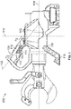
- Figure 1 illustrates a tool 100, in accordance with an example implementation.
- the example implementation described herein references an example cutting tool, it should be understood that the features of this disclosure can be implemented in any other tool (crimping, separation, blanking, etc.).
- any suitable size, shape or type of elements or materials could be used.
- the tool 100 includes a housing 102 and an inclined handle 104 coupled to a top portion of the housing 102. As shown in Figure 1 , the inclined handle 104 extends obliquely from the top portion of the housing.
- the inclined handle 104 defines a handle axis 106 that intersects with a horizontal axis 108 of the housing 102 or the tool 100, and also intersects with a vertical axis 110 of the housing 102 or the tool 100 at respective inclined angles 67 and ⁇ 2.
- This inclined handle 104 protruding from the top portion of the housing 102 facilitates handling the tool 100 by an operator. The operator can hold this tool 100 and move it around by one hand via the inclined handle 104.
- angles 6'I and ⁇ 2 are obtuse and substantially correspond to the angle formed by the hand with the forearm in the so-called "neutral posture.”
- This configuration provides for a convenient, comfortable, safe and efficient grip of the tool 100 during work execution.
- the structural conformation of a grip of the inclined handle 104 allows a force exerted by the operator to carry and handle the tool 100 to be distributed between various muscles, thus allowing for reduced stress compared to straight handles.
- the inclined handle 104 extends upward from the top portion of the housing 102 as opposed to a more conventional gun-type handle that protrudes downward. As such, the operator exerts a pulling force to hold the tool 100 as opposed to a pushing force if a conventional handle is used. This configuration may reduce wobble of the tool 100 when it is powered.
- the inclined handle 104 has a handle housing 112 that provides a user with a comfortable ergonomic handle for operating the tool 100. Particularly, at least a portion of an exterior profile of the handle housing 112 has depressions 114. Figure 1 illustrates three depressions 114; however, more or fewer depressions could be disposed on the handle housing 112.
- the depressions 114 are spatially arranged in series along the portion of the exterior profile of the handle housing 112.
- the depressions 114 may be configured to receive fingers of a user operating the tool 100, and may also include triggers or buttons for operating the tool 100 as described below with respect to Figure 2B .
- the tool 100 further includes a stand 116 rotatably coupled to a bottom of the housing 102.
- the stand 116 is pivotally mounted at a pivot 118 to the housing 102 such that the stand 116 is rotatable about the housing 102.
- the stand 116 can be placed in a first position shown in Figure 1 that enables the tool 100 to be positioned on a work surface while maintaining a desired orientation.
- Figure 2 A illustrates rotation of the stand 116, in accordance with an example implementation.
- the stand 116 may be rotated to several positions, and may be folded underneath the housing 102 when place in position 200.
- the stand 116 could be placed in several other positions shown in dashed lines in Figure 2A .
- FIG. 2B illustrates a cross section of the tool 100, in accordance with an example implementation.
- the tool 100 further includes a hydraulic actuator cylinder 202 coupled to the housing 102.
- a piston 204 is slidably accommodated within the hydraulic actuator cylinder 202, and the piston 204 is coupled to a ram 206.
- the ram 206 is coupled to a carrier 208, which is coupled to links 21 OA and 210B.
- the links 21 OA and 210B are further coupled to one or more jaws, such as jaws 212A and 212B ( Figure 2A shows bothjaws 212A and 212B, whereas Figure 2B shows the jaw 212B).
- the tool 100 may include a battery 213 configured to provide electric power to an electric motor 214.
- the electric motor 214 is configured to drive a pump 216 via a gear reducer 218, and the pump 216 is configured to provide pressurized fluid to the hydraulic actuator cylinder 202 to linearly extend the piston 204 (and the ram 206) therein.
- the piston 204 drives the links 21 OA and 210B, which in turn drive the jaws 212A and 212B toward each other.
- At least one of the jaws, e.g., the jaw 212A may have a blade 214 (shown in Figure 2A ) configured to cut a cable placed between the jaws 212A and 212B.
- the jaws 212A and 212B move away from each other.
- the tool 100 further includes a clevis 220.
- the clevis 220 has a first end coupled to the hydraulic actuator cylinder 202 and a second end coupled to the one or more jaws 212A and 212B.
- the tool 100 further includes a basket-style handle 222 coupled to the clevis 220 and extending upward as shown in Figures 2A and 2B .
- An operator may hold the tool 100 by having one hand gripping the inclined handle 104 and the other hand gripping the basket-style handle 222. This two-handed operation of the tool 100 enables one operator to handle the tool 100 without assistance.
- the basket-style handle 222 may facilitate changing orientation of the tool 100.
- the basket-style handle 222 may be pivotably mounted at pivot 224 to the clevis 220 such that an angle between the basket-style handle 222 and the clevis 220 could be adjustable.
- the tool 100 includes a first button 226 A and a second button 226B disposed in the depressions 114 of the inclined handle 104.
- the button 226A may for example be configured to trigger the tool 100 to extend the piston 204 when pulled, and the other button 226B may be configured to trigger retraction of the piston 204 when pressed as described below.
- the tool 100 may include a controller coupled to or embedded within the housing 102 or anywhere else within the tool 100.
- the controller may be configured to operate the tool 100.
- the controller may be in communication with sensors coupled to the tool 100.
- the controller may also be in communication with the buttons 226A and 226B and components of the actuation mechanism of the tool 100.
- the controller may, in response cause power from the battery 213 to be provided to the motor 214 to extend the piston 204. If the button 226B is pulled, the controller may actuate a release valve 228 to provide a path of high pressure fluid within the hydraulic actuator cylinder 202 to a reservoir.
- a spring 230 disposed within the hydraulic actuator cylinder 202 may be configured to push the piston 204 in a retraction direction, thus causing the hydraulic fluid to be discharged from the hydraulic actuator cylinder 202 to the reservoir.
- the controller may further operate the actuation mechanism based on sensor inputs.
- Example sensor inputs include position sensor information indicating position of the piston 204, pressure sensor information indicating hydraulic pressure within the hydraulic actuator cylinder 202, etc.
- FIGs 3A and 3B illustrate interlocking the buttons 226A and 226B, in accordance with an example implementation.
- the button 226A is pulled so as to trigger the tool 100 and cause the piston 204 to extend. While the button 226A is pulled, the button 226B cannot be pulled.
- the button 226B is pulled so as to cause the piston 204 to retract. While the button 226B is pulled, the button 226A cannot be pulled.
- Figures 4A, 4B , 4C, 4D , 4E , and 4F illustrate components and operation of an interlocking mechanism, in accordance with an example implementation.
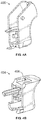
- Figure 4A illustrates a rear perspective view of a trigger cap 400 of the button 226A, in accordance with an example implementation.
- the trigger cap 400 has an interlock stop 402, e.g., a groove, the operation of which is described below.
- Figure 4B illustrates a rear perspective view of a trigger cap 404 of the button 226B, in accordance with an example implementation.
- the trigger cap 404 has an interlock stop 406, e.g., a groove, the operation of which is described below.
- the trigger cap 400 represents the button 226A, and therefore the trigger cap 400 and the button 226A are used interchangeably herein.
- the trigger cap 404 represents the button 226B, and therefore the trigger cap 404 and the button 226B are used interchangeably herein.
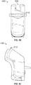
- FIG 4C illustrates a side view of an interlock toggle lever 408, and Figure 4D illustrates a perspective view of the interlock toggle lever 408, in accordance with an example embodiment.
- the toggle lever has a proximal end 409A that is pivotally mounted inside the inclined handle 104 as shown in Figure 4E , and a distal end 409B.
- the distal end 409B is disposed between the trigger cap 400 of the button 226A and the trigger cap 404 of the button 226B.
- the distal end 409B has a protrusion 410 that operates as a power trigger interlock feature.
- the interlock toggle lever 408 also includes a return trigger interlock feature 412.
- the interlock toggle lever 408 also includes a bias spring guide 414 and a bias spring slot 416.
- a torsional spring could be wrapped about the bias spring guide 414 and could have a leg disposed in the bias spring slot 416.
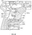
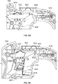
- Figure 4E shows an internal view of the inclined handle 104 to illustrate operation of the interlocking mechanism when the button 226A is pulled, in accordance with an example implementation.
- the trigger cap 400 has a protruding member 418 that, when the button 226A is pulled, touches a contact 420 of a switch 422, thus closing an electric circuit. Closing this electric circuit provides a signal to the controller of the tool 100 indicating that the power trigger (i.e., the button 226A) has been triggered. In response, the controller activates the motor 214 to extend the piston 204 and perform a cutting operation.
- the trigger cap 400 pushes the toggle lever 408 downward against a force of the torsional spring mounted about the bias spring guide 414.
- the torsional spring causes the toggle lever 408 to return back to a neutral position.
- Figure 4F shows an internal view of the inclined handle 104 to illustrate operation of the interlocking mechanism when the button 226B is pulled, in accordance with an example implementation.
- the trigger cap 404 moves backward as a result of pulling the button 226B, the trigger cap 404 pushes the toggle lever 408 upward, thus pushing the protrusion 410 into the interlock stop 402 of the trigger cap 400.
- the trigger cap 400 would not move and the button 226A would not be actuated.
- the trigger cap 404 pushes the toggle lever 408 upward against a force of the torsional spring mounted about the bias spring guide 414.
- the torsional spring causes the toggle lever 408 to return back to a neutral position.
- the tool 100 may have a slide mechanism that controls operation of the buttons 226A and 226B.
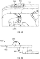
- Figure 5 A illustrates a perspective view of the inclined handle 104 having a toggle switch 500 in a first position, in accordance with an example implementation.
- the inclined handle 104 has a cutout section 502 section on a top surface of the inclined handle 104.
- the toggle switch 500 protrudes through the cutout section 502 and is configured to slide within the cutout section 502 between three positions.
- the first position of the toggle switch 500 is illustrated in Figure 5A .
- the button 226A is locked in an "off state, and cannot be triggered.
- Figure 5B illustrates a perspective view of the inclined handle 104 having the toggle switch 500 in a second position, in accordance with an example implementation.
- the toggle switch 500 When the toggle switch 500 is placed in that second position, the button 226A is in a neutral or floating state and can be freely triggered or released.
- Figure 5C illustrates a perspective view of the inclined handle 104 having the toggle switch 500 in a third position, in accordance with an example implementation.
- the toggle switch 500 When the toggle switch 500 is placed in this third position, the button 226A is in locked in an "on" or triggered state. This position facilitates remote operation of the tool 100 as described below with respect to Figure 7 .
- Figures 6A , 6B , 6C , 6D , 6E , 6F , 6Q and 6H illustrate a slide mechanism that implements operation of the toggle switch 500 and its interaction with the buttons 226A, in accordance with an example implementation.
- Figure 6A illustrates a side view of a slide 600, in accordance with an example implementation.
- the slide 600 includes the toggle switch 500.
- the slide 600 also includes a detent feature 602, a lock-on feature 604, and a lock-off feature 606.
- the features 602, 604, and 606 interact with corresponding features of the trigger cap 400 of the button 226A to implement the operations associated with the three positions described with respect to Figures 5A-5C .
- Figure 6B illustrates a frontal view of the trigger cap 400
- Figure 6C illustrates a side view of the trigger cap 400 to show features corresponding to the features of the slide 600, in accordance with an example implementation.
- the trigger cap 400 has a stepped groove 608, which includes a lock-off feature 610.
- the lock-off feature 610 interacts with the lock-off feature 606 of the slide 600 when the slide 600 and the toggle switch 500 are in the first position shown in Figure 5 A to lock the button 226A in an "off state.
- the trigger cap 400 also has a lock-on feature 612.
- the lock-on feature 612 interacts with the lock-on feature 604 of the slide 600 when the slide 600 and the toggle switch 500 are in the third position shown in Figure 5C to lock the button 226A in an "on" or triggered state.
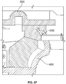
- Figures 6D-6H illustrate interaction between the slide 600 and the trigger cap 400 when the toggle switch 500 is placed in the first position, the second position, and the third position.
- Figures 6D, 6E , and 6F illustrate the slide 600 and the trigger cap 400 while the toggle switch 500 is in the first position. Particularly, Figure 6D illustrates a partial side view of the inclined handle 104 while the toggle switch 500 is in the first position.
- the trigger cap 400 of the button 226A If the trigger cap 400 of the button 226A is in a released (un-triggered) position and the operator moves the toggle switch 500 to the first position as shown in Figure 6D , the trigger cap 400 (and the button 226A) would be locked in an "off state.
- the inclined handle 104 has a detent member 614 that engages the detent feature 602 of the slide 600 when the toggle switch 500 is placed in the first position. This detent configuration retains or secures the slide 600 in that position.
- Figure 6E shows a perspective view of the trigger cap 400 and the toggle switch 500 in the first position
- Figure 6F illustrates a cross section of the trigger cap 400 and the toggle switch 500 in the first position.
- Figures 6E and 6F show that while the toggle switch 500 is in the first position, the lock-off feature 606 of the slide 600 engages with the corresponding lock- off feature 610 of the trigger cap 400.
- the slide 600 prevents the trigger cap 400 from rotating.
- the protruding member 418 of the trigger cap 400 cannot touch the contact 420 of the switch 422.
- the tool 100 cannot be triggered and will be locked in an "off state.
- Figure 6G illustrates the slide 600 and the trigger cap 400 while the toggle switch 500 is in the second position. As shown in Figure 6Q when the slide 600 is placed in the second position, the detent member 614 just touches the slide 600, but does not engage the detent feature 602 of the slide 600.
- the inclined handle 104 includes a spring 616 that engages with the slide 600 at one end and rests on an internal wall surface of the inclined handle 104 at the other end as shown in Figure 6G .
- the slide 600 floats between the detent member 614 and the spring 616.
- the trigger cap 400 can be actuated (i.e., pulled) and released with no interference from the slide 600.
- the toggle switch 500 and the slide 600 are in a neutral position and the button 226A (and the trigger cap 400) can be freely triggered or released.
- Figure 6H illustrates the slide 600 and the trigger cap 400 while the toggle switch 500 is in the third position.
- an operator may pull the trigger cap 400 of the button 226A to trigger or activate the tool 100 (i.e., cause the piston 204 to extend the tool 100 to perform a cutting operation).
- the operator may move the toggle switch 500 to the third position, thus placing the slide 600 in the position shown in Figure 6H .
- the lock-on feature 604 of the slide 600 engages with the corresponding lock-on feature 612 of the trigger cap 400.
- the spring 616 acts on the slide 600 to force the slide 600 into the trigger cap 400.
- another spring 618 forces the trigger cap 400 into the slide 600.
- the trigger cap 400 is locked in this "on” position where the protruding member 418 remains touching the contact 420, and thus the tool 100 remains in a triggered or "on” state.
- This configuration is useful when an operator seeks to operate the tool 100 remotely as described next.
- FIG. 7 illustrates a system 700, in accordance with an example implementation.
- the system 700 includes the tool 100, and a device 702 configured to remotely control the tool 100.
- the tool 100 may include a controller coupled to or embedded within the tool housing 102.
- the controller may be configured to operate the tool 100.
- the controller may be in communication with sensors coupled to the tool 100, and may also be in communication with the buttons 226A and 226B as well as components of the actuation mechanism of the tool 100 (e.g., the battery 213 and the motor 214).
- the controller may, in response, cause power from the battery 213 to be provided to the motor 214.
- the controller may further operate the actuation mechanism based on sensor inputs.
- Example sensor inputs include position sensor information indicating position of the piston 204, pressure sensor information indicating hydraulic pressure, etc.
- the tool 100 may include one or more antennae that facilitate sending and receiving messages to and from other devices, such as the device 702.
- the device 702 can be, for example, a mobile phone, personal digital assistant (PDA), laptop, notebook, or netbook computer, tablet computing device, etc.
- the device 702 may have a user interface to interact with operators/users.
- the tool 100 may be configured to operate in at least two operating modes: a normal mode and a remote-cut mode.
- a normal mode an operator may place a cable between the jaws 212A-212B and pull the trigger button 226A causing the piston 204 to move the jaws 212A- 212B relative to each other and cut the cable.
- the actuation mechanism is powered, e.g., power is provided to the motor 214 that controls motion of the piston 204 via the pump 216. But, as the operator releases the button 226A, power is disconnected from the actuation mechanism.
- this normal mode of operation may be safe if the cable is not energized as the operator can stay close to the tool 100, possibly holding the tool 100, while the cutting operation is being performed.
- the tool 100 may be remotely controlled via the device 702.
- the tool 100 may be in wireless communication with the device 702.
- the tool 100 and the device 702 may exchange signals and messages associated with performance of a cutting operation.
- the device 702 may be used to remotely control the tool 100 to perform a cutting operation while an operator is away from the tool 100.
- a first step associated with the remote-cut mode may involve verifying that a user or operator wants to start a remote-cut operation. For example, an operator may press a button 704 of the device 702 to initiate enabling the remote-cut mode. In response, a processor of the device 702 may generate a display of a message, e.g., "Enable Remote Cut," on a display 706 of the device 702 to alert the operator that the button 704 has been pressed.
- a message e.g., "Enable Remote Cut”
- the device 702 may request a confirmation from the operator. As such, the device 702 may prompt the operator for a second enable criterion in addition to pressing the button 704. For instance, assuming that a button 708 is blue, a display of a message, e.g., "Press 'Blue' to Activate Remote Cut," may be generated on the display 706. The operator may then press the button 708 to confirm that the operater intended to enable the remote-cut mode. Additionally, the device 702 may also determine an amount of time that elapsed between pressing the button 704 and pressing the button 708.
- a display of a message e.g., "Press 'Blue' to Activate Remote Cut”
- the device 702 determines that the operator has intended to initiate the remote-cut mode. If the period of time exceeds the threshold period of time, then the device 702 discards the previous pressing of the button 704, and does not initiate enabling the remote-cut mode.
- a threshold period of time e.g. 10 seconds
- the device 702 verifies the operator's intention to initiate the remote-cut mode. In response, the device 702 may then transmit or send a signal to the tool 100 to command the controller of the tool 100 to prepare for a remote-cut operation.
- the device 702 may request a third enable criterion from the operator.
- a display of a message e.g., "Confirm Remote Cut Pull Tool Trigger”
- the controller of the tool 100 may send a signal/message to the device 702 to confirm that the button 226A has been pulled and that the tool 100 is in the remote-cut mode.
- pulling the button 226 A may power the tool 100 and cause the jaws 212A-212B to move relative to each other.
- pulling the button 226 A does not power the tool 100 and the motor 214 will not be actuated.
- the tool 100 may provide an indication to the operator that the tool 100 is now in the remote-cut mode (e.g., the tool 100 switched from a normal mode of operation to the remote-cut mode of operation).
- the tool 100 may have a light emitting diode (LED) indicator (not shown).
- the controller of the tool 100 may cause the LED indicator to flash or emit light intermittently at a particular frequency (e.g., 2 flashes per second) to notify the operator that the remote-cut mode is enabled.
- the controller may further start a timer upon sending the signal to the device 702. If a threshold period of time (e.g., 2 minutes) lapses from the start of the timer without receiving further communications from the device 702, the controller may cause the tool 100 to disable or exit the remote-cut mode and switch back to the normal mode of operation.
- a threshold period of time e.g. 2 minutes
- a display of a message e.g., "Remote Cut Enabled” may be generated on the display 706 to further confirm to the operator that the remote- cut mode is enabled. Now that the remote-cut mode is enabled, the operator may next prepare the cut location at the tool 100. For instance, the operator may place a cable between the jaws 212A-212B. Flashing of the LED indicator indicates to the operator that the tool 100 is still in the remote-cut mode.
- a second step associated with the remote-cut mode may involve arming or readying the tool 100 before the operator exits the cut location to avoid any hazards.
- the tool 100 may further include the toggle switch 500. If the button 226A is pulled, and then the toggle switch 500 is placed in the third position discussed with respect to Figures 5C and 6H , the button 226A will be locked in an "on” state and the tool 100 is armed.
- the "on" state of the button 226A could also be referred to as an "active" or “enabled” state.
- This process may require both hands of the operator: one hand to pull the button 226A, and a second hand to actuate the toggle switch 500. This two handed requirement is a safety precaution as the operator cannot lock the button 226A in the "on” state accidently by using only one hand.
- the controller of the tool 100 may start a timer when the button 226A is locked in the "on" state by the toggle switch 500. If the button 226A remains depressed for a threshold period of time (e.g., 20 seconds), the controller confirms that the operator intends to arm the tool 100. The operator can disarm the tool 100 with one hand by placing the toggle switch 500 in either the first or second position described herein with respect to Figures 5A and 5B .
- a threshold period of time e.g. 20 seconds
- the controller When the controller confirms that the operator intends the tool 100 to be armed, the controller sends a signal to the device 702 to inform the device 702 that the button 226A is locked in the "on” state and the tool 100 is armed. In response, a display of a message, e.g., "Tool Armed! Press Start to Begin Cut,” may be generated on the display 706.
- a message e.g., "Tool Armed! Press Start to Begin Cut
- a third step associated with the remote-cut mode may involve starting the cutting operation. Now that the tool 100 is armed and ready to perform the cutting operation, the operator exits or has already exited the cutting location to avoid certain hazards. The operator can control the cutting tool remotely via the device 702.
- the operator may be required to press and hold one or more buttons of the device 702 for a particular period of time (e.g., 3 seconds). For instance, the operator may press on buttons 710 and 712 shown in Figure 7 to start the cutting operation remotely.
- the buttons 710 and 712 may be placed on the user interface of the device 702 at respective locations that ensure using both hands of the operator to command starting the cutting operation. Using both hands further confirms the operator's intention to perform a remote cut.
- buttons 710 and 712 may be pressed at substantially the same time (e.g., the operator may begin pressing the button 710 and then within a threshold period of time, such as 100 milli-seconds, begins pressing the other button 712). Requiring the operator to use both hands to send the cutting command further ensures that the operator's hands are away from the tool 100 and threfore enhances operator safety.
- the device 702 If the device 702 confirms that the operator intends to start the cutting operation by pressing both buttons 710 and 712 substantially simultaneously for a particular period of time, the device 702 sends a signal to the tool 100. In response to receiving the signal, the controller of the tool 100 may provide a command to the motor 214 to operate the pump 216 and start the cutting operation. A display of a message, e.g., "Remote Cut Starting - Cutting" may be generated on the display 706 of the device 702 to show the operator that the cutting operation started or is about to start.
- a message e.g., "Remote Cut Starting - Cutting"
- the tool 100 and the device 702 may provide the operator with a status of a cutting operation.
- the controller of the tool 100 may receive information indicating that a cutting operation has been performed successfully. For instance, a hydraulic pressure within the tool 100 may reach a threshold or target pressure value indicating that the piston 204 reached a limit of its travel stroke and thus the cut was successfully performed.
- the piston 204 may have a position sensor that might indicate to the controller that the piston 204 reached the end of its travel stroke. Other indicators are also possible.
- the controller may also determine that a failure occurred during the cutting operation. For instance, the controller may determine or receive sensor information indicating that the piston 204 has stalled or that the battery 213 is overloaded, or other events that might indicate fault with the tool 100.
- the controller of the tool 100 may send a signal to the device 702 to indicate the status of the cutting operation.
- the device 702 may provide indications to the operator regarding the status of the cutting operation. For instance, if the cutting operation has been successful, a display of a message "Cut Complete! may be generated on the display 706. On the other hand, if a fault has occurred and the cutting operation has been stopped, a display of a message "System Fault! may be generated on the display 706.
- the controller of the tool 100 may cause the tool 100 to switch back to the normal mode of operation.
- the normal mode of operation if the operator pulls the trigger button 226A, the motor 214 of the tool 100 would be powered and the piston 204 would start to extend.
- the tool 100 may be configured to respond only to signals received from the device 702, and thus not respond to signals from any other devices.
- the device 702 may be configured to communicate exclusively with the tool 100. In this manner, unintended signals from other devices would not interfere with operation of the tool 100 and the device 702.
- the tool 100 may be assigned a particular communication address.
- the device 702 may have a memory configured to store the particular communication address of the tool 100.
- the device 702 may be configured to receive signals and communications in general only from a tool having a particular communication address, i.e., the tool 100.
- An example communication address may include a media access control (MAC) address.
- the tool 100 may also have the same MAC address stored in its memory, and would pair only with the device 702, which is assigned the same MAC address.
- MAC media access control
Landscapes
- Engineering & Computer Science (AREA)
- Mechanical Engineering (AREA)
- General Engineering & Computer Science (AREA)
- Physics & Mathematics (AREA)
- General Physics & Mathematics (AREA)
- Automation & Control Theory (AREA)
- Portable Power Tools In General (AREA)
- Auxiliary Devices For Machine Tools (AREA)
- Sawing (AREA)
- Shearing Machines (AREA)
Abstract
Description
- The present disclosure relates generally to construction and operation of tools.
- A powered tool may include one or more movable blades that are actuatable by a hydraulic or electromechanical actuation system. By providing power to the actuation system, the blades move relative to each other to perform operations such as cutting, crimping, separation, blanking, etc.
- The present disclosure describes embodiments that relate to systems, apparatuses, tools, and methods associated with a tool having an inclined handle.
- In an example implementation, the present disclosure describes a tool. The tool includes: (i) a housing; (ii) an inclined handle coupled to, and extending obliquely from, a top portion of the housing, where the inclined handle has a first trigger button and a second trigger button; and (iii) an interlocking mechanism disposed in the inclined handle. The interlocking mechanism is configured to disable one of the first trigger button or the second trigger button while the other of the first trigger button or the second trigger button is triggered.
- The foregoing summary is illustrative only and is not intended to be in any way limiting. In addition to the illustrative aspects, embodiments, and features described above, further aspects, embodiments, and features will become apparent by reference to the figures and the following detailed description.
-
-
Figure 1 illustrates a tool, in accordance with an example implementation. -
Figure 2 A illustrates rotation of a stand coupled to the tool ofFigure 1 , in accordance with an example implementation. -
Figure 2B illustrates a cross section of the tool, in accordance with an example implementation. -
Figure 2C illustrates another cross section of the side view of the tool showing retraction of the piston, in accordance with an example implementation. -
Figures 3A-3B illustrate interlocking buttons of the tool shown inFigure 1 , in accordance with an example implementation, in accordance with an example implementation. -
Figure 4A illustrates a rear perspective view of a trigger cap of a first button of the tool, in accordance with an example implementation. -
Figure 4B illustrates a rear perspective view of a trigger cap of a second button of the tool, in accordance with an example implementation. -
Figure 4C illustrates a side view of an interlock toggle lever, in accordance with an example embodiment. -
Figure 4D illustrates a perspective view of the interlock toggle lever ofFigure 4C , in accordance with an example embodiment. -
Figure 4E shows an internal view of an inclined handle to illustrate operation of an interlocking mechanism when a first button is pulled, in accordance with an example implementation. -
Figure 4F shows an internal view of the inclined handle to illustrate operation of the interlocking mechanism when a second button is pulled, in accordance with an example implementation. -
Figure 5A illustrates a perspective view of an inclined handle having a toggle switch in a first position, in accordance with an example implementation. -
Figure 5B illustrates a perspective view of the inclined handle having the toggle switch in a second position, in accordance with an example implementation. -
Figure 5C illustrates a perspective view of the inclined handle having the toggle switch in a second position, in accordance with an example implementation. -
Figure 6A illustrates a side view of a slide, in accordance with an example implementation. -
Figure 6B illustrates a frontal view of a trigger cap to show features corresponding to the features of the slide, in accordance with an example implementation. -
Figure 6C illustrates a side view of the trigger cap to show features corresponding to the features of the slide, in accordance with an example implementation. -
Figure 6D illustrates a partial side view of an inclined handle while a toggle switch is in a first position, in accordance with an example embodiment. -
Figure 6E shows a perspective view of a trigger cap and a toggle switch in a first position, in accordance with an example embodiment. -
Figure 6F illustrates a cross section of a trigger cap and a toggle switch in a first position, in accordance with an example embodiment. -
Figure 6G illustrates a slide and a trigger cap while a toggle switch is in a second position, in accordance with an example embodiment. -
Figure 6H illustrates a slide and a trigger cap while a toggle switch is in a third position, in accordance with an example embodiment. -
Figure 7 illustrates a system, in accordance with an example implementation. - The following detailed description describes various features and functions of the disclosed systems and methods with reference to the accompanying figures. The illustrative system and method embodiments described herein are not meant to be limiting. It may be readily understood that certain aspects of the disclosed systems and methods can be arranged and combined in a variety of different configurations, all of which are contemplated herein.
- Further, unless context suggests otherwise, the features illustrated in each of the figures may be used in combination with one another. Thus, the figures should be generally viewed as component aspects of one or more overall implementations, with the understanding that not all illustrated features are necessary for each implementation.
- Additionally, any enumeration of elements, blocks, or steps in this specification or the claims is for purposes of clarity. Thus, such enumeration should not be interpreted to require or imply that these elements, blocks, or steps adhere to a particular arrangement or are carried out in a particular order.
- By the term "substantially" it is meant that the recited characteristic, parameter, or value need not be achieved exactly, but that deviations or variations, including for example, tolerances, measurement error, measurement accuracy limitations and other factors known to skill in the art, may occur in amounts that do not preclude the effect the characteristic was intended to provide.
- A powered tool is a tool that is actuated by an additional power source and mechanism other than the solely manual labor used with hand tools. Example powered tools employ electric motors, hydraulic systems, etc. to power the tool.
- These tools could be heavy and handling them by an operator could be challenging. Further, in examples, electrical equipment may be maintained while operating at high voltages. An example maintenance operation may involve cutting a live line. In this example, it is desirable to perform a cable cutting operation by way of a remotely controlled cutting tool so as to insulate workers from any electrical hazards. In other examples, the line might not be easily reachable. For instance, the cable may be in an underwater environment, and may thus be cut via remote control of the cutting tool.
- Disclosed herein are systems, tools, and apparatuses that provide for ergonomic handling of powered tools as wells remote control of a cutting tool to insulate workers from hazardous environments.
-
Figure 1 illustrates atool 100, in accordance with an example implementation. Although the example implementation described herein references an example cutting tool, it should be understood that the features of this disclosure can be implemented in any other tool (crimping, separation, blanking, etc.). In addition, any suitable size, shape or type of elements or materials could be used. - The
tool 100 includes ahousing 102 and aninclined handle 104 coupled to a top portion of thehousing 102. As shown inFigure 1 , theinclined handle 104 extends obliquely from the top portion of the housing. - Particularly, as shown in
Figure 1 , theinclined handle 104 defines ahandle axis 106 that intersects with ahorizontal axis 108 of thehousing 102 or thetool 100, and also intersects with avertical axis 110 of thehousing 102 or thetool 100 at respective inclined angles 67 and Θ2. Thisinclined handle 104 protruding from the top portion of thehousing 102 facilitates handling thetool 100 by an operator. The operator can hold thistool 100 and move it around by one hand via theinclined handle 104. - Further, the angles 6'I and Θ2 are obtuse and substantially correspond to the angle formed by the hand with the forearm in the so-called "neutral posture." This configuration provides for a convenient, comfortable, safe and efficient grip of the
tool 100 during work execution. In particular, the structural conformation of a grip of theinclined handle 104 allows a force exerted by the operator to carry and handle thetool 100 to be distributed between various muscles, thus allowing for reduced stress compared to straight handles. - Further, the
inclined handle 104 extends upward from the top portion of thehousing 102 as opposed to a more conventional gun-type handle that protrudes downward. As such, the operator exerts a pulling force to hold thetool 100 as opposed to a pushing force if a conventional handle is used. This configuration may reduce wobble of thetool 100 when it is powered. - Further, the
inclined handle 104 has a handle housing 112 that provides a user with a comfortable ergonomic handle for operating thetool 100. Particularly, at least a portion of an exterior profile of the handle housing 112 has depressions 114.Figure 1 illustrates threedepressions 114; however, more or fewer depressions could be disposed on the handle housing 112. - The
depressions 114 are spatially arranged in series along the portion of the exterior profile of the handle housing 112. Thedepressions 114 may be configured to receive fingers of a user operating thetool 100, and may also include triggers or buttons for operating thetool 100 as described below with respect toFigure 2B . - The
tool 100 further includes astand 116 rotatably coupled to a bottom of thehousing 102. Particularly, thestand 116 is pivotally mounted at apivot 118 to thehousing 102 such that thestand 116 is rotatable about thehousing 102. Thestand 116 can be placed in a first position shown inFigure 1 that enables thetool 100 to be positioned on a work surface while maintaining a desired orientation. -
Figure 2 A illustrates rotation of thestand 116, in accordance with an example implementation. As shown inFigure 2 A , thestand 116 may be rotated to several positions, and may be folded underneath thehousing 102 when place inposition 200. However, thestand 116 could be placed in several other positions shown in dashed lines inFigure 2A . -
Figure 2B illustrates a cross section of thetool 100, in accordance with an example implementation. Thetool 100 further includes ahydraulic actuator cylinder 202 coupled to thehousing 102. Apiston 204 is slidably accommodated within thehydraulic actuator cylinder 202, and thepiston 204 is coupled to aram 206. Theram 206 is coupled to acarrier 208, which is coupled to links 21 OA and 210B. The links 21 OA and 210B are further coupled to one or more jaws, such asjaws Figure 2A showsbothjaws Figure 2B shows thejaw 212B). - The
tool 100 may include abattery 213 configured to provide electric power to anelectric motor 214. Theelectric motor 214 is configured to drive apump 216 via agear reducer 218, and thepump 216 is configured to provide pressurized fluid to thehydraulic actuator cylinder 202 to linearly extend the piston 204 (and the ram 206) therein. As thepiston 204 extends within thehydraulic actuator cylinder 202, thepiston 204 drives the links 21 OA and 210B, which in turn drive thejaws jaw 212A, may have a blade 214 (shown inFigure 2A ) configured to cut a cable placed between thejaws piston 204 retracts, thejaws - As shown in
Figure 2A , thetool 100 further includes aclevis 220. Theclevis 220 has a first end coupled to thehydraulic actuator cylinder 202 and a second end coupled to the one ormore jaws tool 100 further includes a basket-style handle 222 coupled to theclevis 220 and extending upward as shown inFigures 2A and2B . - An operator may hold the
tool 100 by having one hand gripping theinclined handle 104 and the other hand gripping the basket-style handle 222. This two-handed operation of thetool 100 enables one operator to handle thetool 100 without assistance. Also, the basket-style handle 222 may facilitate changing orientation of thetool 100. Further, the basket-style handle 222 may be pivotably mounted atpivot 224 to theclevis 220 such that an angle between the basket-style handle 222 and theclevis 220 could be adjustable. - As shown in
Figure 2B , thetool 100 includes afirst button 226 A and asecond button 226B disposed in thedepressions 114 of theinclined handle 104. Thebutton 226A may for example be configured to trigger thetool 100 to extend thepiston 204 when pulled, and theother button 226B may be configured to trigger retraction of thepiston 204 when pressed as described below. - The
tool 100 may include a controller coupled to or embedded within thehousing 102 or anywhere else within thetool 100. The controller may be configured to operate thetool 100. For example, the controller may be in communication with sensors coupled to thetool 100. The controller may also be in communication with thebuttons tool 100. - For instance, if the
button 226A is pulled, the controller may, in response cause power from thebattery 213 to be provided to themotor 214 to extend thepiston 204. If thebutton 226B is pulled, the controller may actuate arelease valve 228 to provide a path of high pressure fluid within thehydraulic actuator cylinder 202 to a reservoir. In an example, aspring 230 disposed within thehydraulic actuator cylinder 202 may be configured to push thepiston 204 in a retraction direction, thus causing the hydraulic fluid to be discharged from thehydraulic actuator cylinder 202 to the reservoir. - The controller may further operate the actuation mechanism based on sensor inputs. Example sensor inputs include position sensor information indicating position of the
piston 204, pressure sensor information indicating hydraulic pressure within thehydraulic actuator cylinder 202, etc. - In some examples, it is desirable for safety reasons to interlock operation of the
buttons Figures 3A and 3B illustrate interlocking thebuttons Figure 3 A , thebutton 226A is pulled so as to trigger thetool 100 and cause thepiston 204 to extend. While thebutton 226A is pulled, thebutton 226B cannot be pulled. Similarly, as shown inFigure 3B , thebutton 226B is pulled so as to cause thepiston 204 to retract. While thebutton 226B is pulled, thebutton 226A cannot be pulled.Figures 4A, 4B ,4C, 4D ,4E , and4F illustrate components and operation of an interlocking mechanism, in accordance with an example implementation. -
Figure 4A illustrates a rear perspective view of atrigger cap 400 of thebutton 226A, in accordance with an example implementation. Thetrigger cap 400 has aninterlock stop 402, e.g., a groove, the operation of which is described below.Figure 4B illustrates a rear perspective view of atrigger cap 404 of thebutton 226B, in accordance with an example implementation. Thetrigger cap 404 has aninterlock stop 406, e.g., a groove, the operation of which is described below. Thetrigger cap 400 represents thebutton 226A, and therefore thetrigger cap 400 and thebutton 226A are used interchangeably herein. Similarly, thetrigger cap 404 represents thebutton 226B, and therefore thetrigger cap 404 and thebutton 226B are used interchangeably herein. -
Figure 4C illustrates a side view of aninterlock toggle lever 408, andFigure 4D illustrates a perspective view of theinterlock toggle lever 408, in accordance with an example embodiment. The toggle lever has aproximal end 409A that is pivotally mounted inside theinclined handle 104 as shown inFigure 4E , and adistal end 409B. Thedistal end 409B is disposed between thetrigger cap 400 of thebutton 226A and thetrigger cap 404 of thebutton 226B. - The
distal end 409B has aprotrusion 410 that operates as a power trigger interlock feature. Theinterlock toggle lever 408 also includes a returntrigger interlock feature 412. Theinterlock toggle lever 408 also includes abias spring guide 414 and abias spring slot 416. A torsional spring could be wrapped about thebias spring guide 414 and could have a leg disposed in thebias spring slot 416. -
Figure 4E shows an internal view of theinclined handle 104 to illustrate operation of the interlocking mechanism when thebutton 226A is pulled, in accordance with an example implementation. As shown, thetrigger cap 400 has a protrudingmember 418 that, when thebutton 226A is pulled, touches acontact 420 of aswitch 422, thus closing an electric circuit. Closing this electric circuit provides a signal to the controller of thetool 100 indicating that the power trigger (i.e., thebutton 226A) has been triggered. In response, the controller activates themotor 214 to extend thepiston 204 and perform a cutting operation. - As illustrated in
Figure 4E , when thetrigger cap 400 moves backward as a result of pulling thebutton 226 A, thetrigger cap 400 pushes theprotrusion 410 of thetoggle lever 408, thus pushing the returntrigger interlock feature 412 into the interlock stop 406 of thetrigger cap 404. As a result, if the operator attempts to pull thetrigger cap 404 backward to trigger thebutton 226B, thetrigger cap 404 is prevented from moving and thebutton 226B would not be actuated. - Further, the
trigger cap 400 pushes thetoggle lever 408 downward against a force of the torsional spring mounted about thebias spring guide 414. When thetrigger cap 400 is released, the torsional spring causes thetoggle lever 408 to return back to a neutral position. - Similarly,
Figure 4F shows an internal view of theinclined handle 104 to illustrate operation of the interlocking mechanism when thebutton 226B is pulled, in accordance with an example implementation. When thetrigger cap 404 moves backward as a result of pulling thebutton 226B, thetrigger cap 404 pushes thetoggle lever 408 upward, thus pushing theprotrusion 410 into the interlock stop 402 of thetrigger cap 400. As a result, if the operator attempts to pull thetrigger cap 400 backward to trigger thebutton 226A, thetrigger cap 400 would not move and thebutton 226A would not be actuated. - The
trigger cap 404 pushes thetoggle lever 408 upward against a force of the torsional spring mounted about thebias spring guide 414. When thetrigger cap 404 is released, the torsional spring causes thetoggle lever 408 to return back to a neutral position. - In this manner, because of the interlocking mechanism described by
Figures 4A-4F , if either of thebuttons tool 100 safer. - In addition to the interlocking mechanism described above, the
tool 100 may have a slide mechanism that controls operation of thebuttons - For example,
Figure 5 A illustrates a perspective view of theinclined handle 104 having atoggle switch 500 in a first position, in accordance with an example implementation. As shown, theinclined handle 104 has acutout section 502 section on a top surface of theinclined handle 104. Thetoggle switch 500 protrudes through thecutout section 502 and is configured to slide within thecutout section 502 between three positions. For example, the first position of thetoggle switch 500 is illustrated inFigure 5A . When thetoggle switch 500 is placed in that first position, thebutton 226A is locked in an "off state, and cannot be triggered. -
Figure 5B illustrates a perspective view of theinclined handle 104 having thetoggle switch 500 in a second position, in accordance with an example implementation. When thetoggle switch 500 is placed in that second position, thebutton 226A is in a neutral or floating state and can be freely triggered or released. -
Figure 5C illustrates a perspective view of theinclined handle 104 having thetoggle switch 500 in a third position, in accordance with an example implementation. When thetoggle switch 500 is placed in this third position, thebutton 226A is in locked in an "on" or triggered state. This position facilitates remote operation of thetool 100 as described below with respect toFigure 7 . -
Figures 6A ,6B ,6C ,6D ,6E ,6F ,6Q and 6H illustrate a slide mechanism that implements operation of thetoggle switch 500 and its interaction with thebuttons 226A, in accordance with an example implementation. Particularly,Figure 6A illustrates a side view of aslide 600, in accordance with an example implementation. As shown, theslide 600 includes thetoggle switch 500. Theslide 600 also includes adetent feature 602, a lock-onfeature 604, and a lock-off feature 606. Thefeatures trigger cap 400 of thebutton 226A to implement the operations associated with the three positions described with respect toFigures 5A-5C . -
Figure 6B illustrates a frontal view of thetrigger cap 400, andFigure 6C illustrates a side view of thetrigger cap 400 to show features corresponding to the features of theslide 600, in accordance with an example implementation. As shown inFigure 6B , thetrigger cap 400 has a steppedgroove 608, which includes a lock-off feature 610. The lock-off feature 610 interacts with the lock-off feature 606 of theslide 600 when theslide 600 and thetoggle switch 500 are in the first position shown inFigure 5 A to lock thebutton 226A in an "off state. - As shown in
Figure 6C , thetrigger cap 400 also has a lock-onfeature 612. The lock-onfeature 612 interacts with the lock-onfeature 604 of theslide 600 when theslide 600 and thetoggle switch 500 are in the third position shown inFigure 5C to lock thebutton 226A in an "on" or triggered state. - To further illustrate the three states described above,
Figures 6D-6H illustrate interaction between theslide 600 and thetrigger cap 400 when thetoggle switch 500 is placed in the first position, the second position, and the third position. -
Figures 6D, 6E , and6F illustrate theslide 600 and thetrigger cap 400 while thetoggle switch 500 is in the first position. Particularly,Figure 6D illustrates a partial side view of theinclined handle 104 while thetoggle switch 500 is in the first position. - If the
trigger cap 400 of thebutton 226A is in a released (un-triggered) position and the operator moves thetoggle switch 500 to the first position as shown inFigure 6D , the trigger cap 400 (and thebutton 226A) would be locked in an "off state. As shown inFigure 6D , theinclined handle 104 has adetent member 614 that engages thedetent feature 602 of theslide 600 when thetoggle switch 500 is placed in the first position. This detent configuration retains or secures theslide 600 in that position. -
Figure 6E shows a perspective view of thetrigger cap 400 and thetoggle switch 500 in the first position, andFigure 6F illustrates a cross section of thetrigger cap 400 and thetoggle switch 500 in the first position.Figures 6E and6F show that while thetoggle switch 500 is in the first position, the lock-off feature 606 of theslide 600 engages with the corresponding lock-off feature 610 of thetrigger cap 400. - At this position, the
slide 600 prevents thetrigger cap 400 from rotating. Thus, referring back toFigure 6D , the protrudingmember 418 of thetrigger cap 400 cannot touch thecontact 420 of theswitch 422. As a result, thetool 100 cannot be triggered and will be locked in an "off state. -
Figure 6G illustrates theslide 600 and thetrigger cap 400 while thetoggle switch 500 is in the second position. As shown inFigure 6Q when theslide 600 is placed in the second position, thedetent member 614 just touches theslide 600, but does not engage thedetent feature 602 of theslide 600. - Further, the
inclined handle 104 includes aspring 616 that engages with theslide 600 at one end and rests on an internal wall surface of theinclined handle 104 at the other end as shown inFigure 6G . At this position, theslide 600 floats between thedetent member 614 and thespring 616. Thus, thetrigger cap 400 can be actuated (i.e., pulled) and released with no interference from theslide 600. As such, thetoggle switch 500 and theslide 600 are in a neutral position and thebutton 226A (and the trigger cap 400) can be freely triggered or released. -
Figure 6H illustrates theslide 600 and thetrigger cap 400 while thetoggle switch 500 is in the third position. As shown inFigure 6H , an operator may pull thetrigger cap 400 of thebutton 226A to trigger or activate the tool 100 (i.e., cause thepiston 204 to extend thetool 100 to perform a cutting operation). To lock thetrigger cap 400 in the "on" state, the operator may move thetoggle switch 500 to the third position, thus placing theslide 600 in the position shown inFigure 6H . At this position, the lock-onfeature 604 of theslide 600 engages with the corresponding lock-onfeature 612 of thetrigger cap 400. Further, thespring 616 acts on theslide 600 to force theslide 600 into thetrigger cap 400. At the same time, anotherspring 618 forces thetrigger cap 400 into theslide 600. In this configuration, thetrigger cap 400 is locked in this "on" position where the protrudingmember 418 remains touching thecontact 420, and thus thetool 100 remains in a triggered or "on" state. This configuration is useful when an operator seeks to operate thetool 100 remotely as described next. -
Figure 7 illustrates asystem 700, in accordance with an example implementation. Thesystem 700 includes thetool 100, and adevice 702 configured to remotely control thetool 100. As mentioned above, thetool 100 may include a controller coupled to or embedded within thetool housing 102. The controller may be configured to operate thetool 100. For example, the controller may be in communication with sensors coupled to thetool 100, and may also be in communication with thebuttons battery 213 and the motor 214). For instance, if thebutton 226A is pulled, the controller may, in response, cause power from thebattery 213 to be provided to themotor 214. The controller may further operate the actuation mechanism based on sensor inputs. Example sensor inputs include position sensor information indicating position of thepiston 204, pressure sensor information indicating hydraulic pressure, etc. - Additionally, the
tool 100 may include one or more antennae that facilitate sending and receiving messages to and from other devices, such as thedevice 702. Thedevice 702 can be, for example, a mobile phone, personal digital assistant (PDA), laptop, notebook, or netbook computer, tablet computing device, etc. Thedevice 702 may have a user interface to interact with operators/users. - The
tool 100 may be configured to operate in at least two operating modes: a normal mode and a remote-cut mode. In the normal mode, an operator may place a cable between thejaws 212A-212B and pull thetrigger button 226A causing thepiston 204 to move thejaws 212A- 212B relative to each other and cut the cable. As long as the operator is pulling thebutton 226A, the actuation mechanism is powered, e.g., power is provided to themotor 214 that controls motion of thepiston 204 via thepump 216. But, as the operator releases thebutton 226A, power is disconnected from the actuation mechanism. Thus, this normal mode of operation may be safe if the cable is not energized as the operator can stay close to thetool 100, possibly holding thetool 100, while the cutting operation is being performed. - In the remote-cut mode, however, the
tool 100 may be remotely controlled via thedevice 702. Thetool 100 may be in wireless communication with thedevice 702. Thus, thetool 100 and thedevice 702 may exchange signals and messages associated with performance of a cutting operation. Particularly, thedevice 702 may be used to remotely control thetool 100 to perform a cutting operation while an operator is away from thetool 100. - A first step associated with the remote-cut mode may involve verifying that a user or operator wants to start a remote-cut operation. For example, an operator may press a
button 704 of thedevice 702 to initiate enabling the remote-cut mode. In response, a processor of thedevice 702 may generate a display of a message, e.g., "Enable Remote Cut," on adisplay 706 of thedevice 702 to alert the operator that thebutton 704 has been pressed. - To ensure that the button has been pressed intentionally, the
device 702 may request a confirmation from the operator. As such, thedevice 702 may prompt the operator for a second enable criterion in addition to pressing thebutton 704. For instance, assuming that abutton 708 is blue, a display of a message, e.g., "Press 'Blue' to Activate Remote Cut," may be generated on thedisplay 706. The operator may then press thebutton 708 to confirm that the operater intended to enable the remote-cut mode. Additionally, thedevice 702 may also determine an amount of time that elapsed between pressing thebutton 704 and pressing thebutton 708. If the amount of time is less than a threshold period of time, e.g., 10 seconds, then thedevice 702 determines that the operator has intended to initiate the remote-cut mode. If the period of time exceeds the threshold period of time, then thedevice 702 discards the previous pressing of thebutton 704, and does not initiate enabling the remote-cut mode. - Assuming that the
button 708 was pressed within the threshold amount of time, thedevice 702 verifies the operator's intention to initiate the remote-cut mode. In response, thedevice 702 may then transmit or send a signal to thetool 100 to command the controller of thetool 100 to prepare for a remote-cut operation. - Further, in an example, the
device 702 may request a third enable criterion from the operator. Particularly, a display of a message, e.g., "Confirm Remote Cut Pull Tool Trigger," may be generated on thedisplay 706 to prompt the operator to actuate or pull thetrigger button 226A of thetool 100. If the operator pulls thebutton 226A, the controller of thetool 100 may send a signal/message to thedevice 702 to confirm that thebutton 226A has been pulled and that thetool 100 is in the remote-cut mode. - It should be noted that if the
tool 100 is in the normal mode of operation, pulling thebutton 226 A may power thetool 100 and cause thejaws 212A-212B to move relative to each other. However, because thetool 100 had received the signal from thedevice 702 that commands thetool 100 to prepare for the remote-cut mode, pulling thebutton 226 A does not power thetool 100 and themotor 214 will not be actuated. - In addition to sending the signal to the
device 702, thetool 100 may provide an indication to the operator that thetool 100 is now in the remote-cut mode (e.g., thetool 100 switched from a normal mode of operation to the remote-cut mode of operation). For instance, thetool 100 may have a light emitting diode (LED) indicator (not shown). The controller of thetool 100 may cause the LED indicator to flash or emit light intermittently at a particular frequency (e.g., 2 flashes per second) to notify the operator that the remote-cut mode is enabled. - In an example, the controller may further start a timer upon sending the signal to the
device 702. If a threshold period of time (e.g., 2 minutes) lapses from the start of the timer without receiving further communications from thedevice 702, the controller may cause thetool 100 to disable or exit the remote-cut mode and switch back to the normal mode of operation. - Upon receiving the signal at the
device 702, a display of a message, e.g., "Remote Cut Enabled", may be generated on thedisplay 706 to further confirm to the operator that the remote- cut mode is enabled. Now that the remote-cut mode is enabled, the operator may next prepare the cut location at thetool 100. For instance, the operator may place a cable between thejaws 212A-212B. Flashing of the LED indicator indicates to the operator that thetool 100 is still in the remote-cut mode. - A second step associated with the remote-cut mode may involve arming or readying the
tool 100 before the operator exits the cut location to avoid any hazards. For example, as discussed herein, thetool 100 may further include thetoggle switch 500. If thebutton 226A is pulled, and then thetoggle switch 500 is placed in the third position discussed with respect toFigures 5C and6H , thebutton 226A will be locked in an "on" state and thetool 100 is armed. The "on" state of thebutton 226A could also be referred to as an "active" or "enabled" state. This process may require both hands of the operator: one hand to pull thebutton 226A, and a second hand to actuate thetoggle switch 500. This two handed requirement is a safety precaution as the operator cannot lock thebutton 226A in the "on" state accidently by using only one hand. - In an example, the controller of the
tool 100 may start a timer when thebutton 226A is locked in the "on" state by thetoggle switch 500. If thebutton 226A remains depressed for a threshold period of time (e.g., 20 seconds), the controller confirms that the operator intends to arm thetool 100. The operator can disarm thetool 100 with one hand by placing thetoggle switch 500 in either the first or second position described herein with respect toFigures 5A and 5B . - When the controller confirms that the operator intends the
tool 100 to be armed, the controller sends a signal to thedevice 702 to inform thedevice 702 that thebutton 226A is locked in the "on" state and thetool 100 is armed. In response, a display of a message, e.g., "Tool Armed! Press Start to Begin Cut," may be generated on thedisplay 706. - A third step associated with the remote-cut mode may involve starting the cutting operation. Now that the
tool 100 is armed and ready to perform the cutting operation, the operator exits or has already exited the cutting location to avoid certain hazards. The operator can control the cutting tool remotely via thedevice 702. - In an example, to confirm that the operator intends to command the
tool 100 to cut a cable placed between thejaws device 702 for a particular period of time (e.g., 3 seconds). For instance, the operator may press onbuttons 710 and 712 shown inFigure 7 to start the cutting operation remotely. Thebuttons 710 and 712 may be placed on the user interface of thedevice 702 at respective locations that ensure using both hands of the operator to command starting the cutting operation. Using both hands further confirms the operator's intention to perform a remote cut. Thebuttons 710 and 712 may be pressed at substantially the same time (e.g., the operator may begin pressing the button 710 and then within a threshold period of time, such as 100 milli-seconds, begins pressing the other button 712). Requiring the operator to use both hands to send the cutting command further ensures that the operator's hands are away from thetool 100 and threfore enhances operator safety. - If the
device 702 confirms that the operator intends to start the cutting operation by pressing bothbuttons 710 and 712 substantially simultaneously for a particular period of time, thedevice 702 sends a signal to thetool 100. In response to receiving the signal, the controller of thetool 100 may provide a command to themotor 214 to operate thepump 216 and start the cutting operation. A display of a message, e.g., "Remote Cut Starting - Cutting" may be generated on thedisplay 706 of thedevice 702 to show the operator that the cutting operation started or is about to start. - Additionally, the
tool 100 and thedevice 702 may provide the operator with a status of a cutting operation. In an example, the controller of thetool 100 may receive information indicating that a cutting operation has been performed successfully. For instance, a hydraulic pressure within thetool 100 may reach a threshold or target pressure value indicating that thepiston 204 reached a limit of its travel stroke and thus the cut was successfully performed. As another example, thepiston 204 may have a position sensor that might indicate to the controller that thepiston 204 reached the end of its travel stroke. Other indicators are also possible. - On the other hand, the controller may also determine that a failure occurred during the cutting operation. For instance, the controller may determine or receive sensor information indicating that the
piston 204 has stalled or that thebattery 213 is overloaded, or other events that might indicate fault with thetool 100. - Whether the cutting operation is successful or an error has occurred, the controller of the
tool 100 may send a signal to thedevice 702 to indicate the status of the cutting operation. When thedevice 702 receives the signal, thedevice 702 may provide indications to the operator regarding the status of the cutting operation. For instance, if the cutting operation has been successful, a display of a message "Cut Complete!" may be generated on thedisplay 706. On the other hand, if a fault has occurred and the cutting operation has been stopped, a display of a message "System Fault!" may be generated on thedisplay 706. - Upon completion of the cutting operation, the controller of the
tool 100 may cause thetool 100 to switch back to the normal mode of operation. As mentioned herein, in the normal mode of operation, if the operator pulls thetrigger button 226A, themotor 214 of thetool 100 would be powered and thepiston 204 would start to extend. - To enhance safety of the system described above, it is desirable to ensure exclusive one-to-one pairing between the
device 702 and thetool 100. In other words, thetool 100 may be configured to respond only to signals received from thedevice 702, and thus not respond to signals from any other devices. Similarly, thedevice 702 may be configured to communicate exclusively with thetool 100. In this manner, unintended signals from other devices would not interfere with operation of thetool 100 and thedevice 702. - As an example, to ensure exclusive one-to-one pairing between the
tool 100 and thedevice 702, thetool 100 may be assigned a particular communication address. Further, thedevice 702 may have a memory configured to store the particular communication address of thetool 100. Thedevice 702 may be configured to receive signals and communications in general only from a tool having a particular communication address, i.e., thetool 100. An example communication address may include a media access control (MAC) address. Further, thetool 100 may also have the same MAC address stored in its memory, and would pair only with thedevice 702, which is assigned the same MAC address. - It should be understood that arrangements described herein are for purposes of example only. As such, those skilled in the art will appreciate that other arrangements and other elements (e.g., machines, interfaces, orders, and groupings of operations, etc.) can be used instead, and some elements may be omitted altogether according to the desired results.
- While various aspects and implementations have been disclosed herein, other aspects and implementations will be apparent to those skilled in the art. The various aspects and implementations disclosed herein are for purposes of illustration and are not intended to be limiting, with the true scope being indicated by the following claims, along with the full scope of equivalents to which such claims are entitled. It is also to be understood that the terminology used herein is for the purpose of describing particular implementations only, and is not intended to be limiting.
- Features of the invention, which are not claims, are set out in the following clauses:
- 1. A tool comprising:
- a housing;
- an inclined handle coupled to, and extending obliquely from, a top portion of the housing, wherein the inclined handle has a first trigger button and a second trigger button; and
- an interlocking mechanism disposed in the inclined handle, wherein the interlocking mechanism is configured to disable one of the first trigger button or the second trigger button while the other of the first trigger button or the second trigger button is triggered.
- 2. The tool of Clause 1, further comprising:
a toggle switch configured to assume one of at least three positions, wherein:- when positioned at a first position, the toggle switch locks one of the first trigger button or the second trigger button in a released state,
- when positioned at a second position, the toggle switch is in a neutral state, and when positioned at a third position, the toggle switch locks one of the first trigger button or the second trigger button in a triggered state.
- 3. The tool of Clause 2, wherein positioning the toggle switch at the second position enables the first trigger button or the second trigger button to be triggered or released.
- 4. The tool of Clause 2, wherein the inclined handle includes a cutout section on a top surface of the inclined handle, wherein the toggle switch protrudes through the cutout section and is configured to slide within the cutout section between the three positions.
- 5. The tool of Clause 2, further comprising:
- an actuator coupled to the housing;
- one or more jaws coupled to the actuator; and
- a controller coupled to the housing, wherein the controller is in wireless communication with a remote device, and wherein the controller is configured to perform operations comprising:
- receiving a first signal from the remote device indicating a request to operate the tool remotely,
- receiving information indicating that the first trigger button has been locked in a triggered state by way of the toggle switch being in the third position,
- sending a second signal to the remote device indicating that the first trigger button has been locked in the triggered state, and
- in response to receiving a third signal from the remote device, causing the actuator to move the one or more jaws to operate the tool remotely.
- 6. The tool of Clause 5, wherein the controller is configured to operate the tool in a normal mode or a remote-cut mode, wherein:
- in the normal mode, the controller operates the actuator to cause the one or more jaws to move in response to the first trigger button being in the triggered state, and
- in the remote-cut mode, the controller operates the actuator to cause the one or more jaws to move in response to (i) receiving the third signal from the remote device, and (ii) the toggle switch being in the third position.
- 7. The tool of Clause 6, wherein the operations further comprise:
switching the tool from operating in the normal mode to the remote-cut mode in response to receiving at least the first signal. - 8. The tool of Clause 6, wherein the operations further comprise:
- determining that remote operation of the tool has been successful; and
- responsively, switching the tool from operating in the remote-cut mode into the normal mode.
- 9. The tool of Clause 1, wherein the inclined handle defines a handle axis, which intersects with a horizontal axis and a vertical axis of the housing at respective inclined angles.
- 10. The tool of Clause 1, further comprising:
wherein at least a portion of an exterior profile of the inclined handle comprises a first depression and a second depression spatially arranged in series along the portion of the exterior profile, and wherein the first trigger button is disposed in the first depression and the second trigger button is disposed in the second depression. - 11. The tool of Clause 1, further comprising:
a stand rotatably coupled to a bottom of the housing, wherein the stand is rotatable between at least two positions, wherein in a first position, the stand enables the tool to be positioned on a work surface while maintaining a desired orientation, and in a second position, the stand is folded underneath the housing. - 12. The tool of Clause 1, further comprising:
- a hydraulic actuator cylinder coupled to the housing;
- a piston slidably accommodated within the hydraulic actuator cylinder;
- a ram coupled to the piston and configured to drive one or more jaws, wherein the first trigger button is configured to cause the piston to extend and the one or more jaws to move toward each other, and the second trigger buttons is configured to cause the piston to retract and the one or more jaws to move away from each other.
- 13. The tool of Clause 12, further comprising:
- a clevis having a first end coupled to the hydraulic actuator cylinder and a second end coupled to the one or more jaws; and
- a basket-style handle coupled to the clevis and extending upward.
- 14. The tool of Clause 13, wherein the basket-style handle is pivotably mounted to the clevis such that an angle between the basket-style handle and the clevis is adjustable.
- 15. The tool of Clause 1, wherein the interlocking mechanism comprises: a toggle lever having a proximal end and a distal end, the proximal end being pivotably mounted inside the inclined handle, and the distal end being disposed between the first trigger button and the second trigger button.
- 16. The tool of Clause 1, wherein the first trigger button includes a groove at a bottom end of the first trigger button, and the second trigger button includes a respective groove at a top end of the second trigger button, such that:
- when the first trigger button is pulled, the toggle lever rotates downward and the distal end of the first trigger button engages the respective groove of the second trigger button thereby preventing the second trigger button from being triggered, and
- when the second trigger button is pulled, the toggle lever is pushed upward and the distal end of the first trigger button engages the groove of the first trigger button thereby preventing the first trigger button from being triggered.
Claims (15)
- A tool comprising:a housing;a handle coupled to, and extending from, the housing, wherein the handle has a first trigger button and a second trigger button; andan interlocking mechanism disposed in the handle, wherein the interlocking mechanism comprises a toggle lever configured to prevent one of the first trigger button or the second trigger button from being triggered while the other of the first trigger button or the second trigger button is triggered.
- The tool of claim 1, further comprising:
a toggle switch configured to assume one of at least three positions, wherein:when positioned at a first position, the toggle switch locks one of the first trigger button or the second trigger button in a released state,when positioned at a second position, the toggle switch is in a neutral state, andwhen positioned at a third position, the toggle switch locks one of the first trigger button or the second trigger button in a triggered state. - The tool of claim 2, wherein positioning the toggle switch at the second position enables the first trigger button or the second trigger button to be triggered or released.
- The tool of claim 2, wherein the handle includes a cutout section on a top surface of the handle, and the toggle switch protrudes through the cutout section and is configured to slide within the cutout section between the three positions, and wherein the handle extends obliquely from a top portion of the housing and defines a handle axis, which intersects with a horizontal axis and a vertical axis of the housing at respective inclined angles.
- The tool of claim 2, further comprising:an actuator coupled to the housing;one or more jaws coupled to the actuator; anda controller coupled to the housing, wherein the controller is in wireless communication with a remote device and wherein the controller is configured to perform operations comprising:receiving a first signal from the remote device indicating a request to operate the tool remotely,receiving information indicating that the first trigger button has been locked in the triggered state by way of the toggle switch being in the third position, andsending a second signal to the remote device indicating that the first trigger button has been locked in the triggered state.
- The tool of claim 5, wherein the controller is configured to operate the tool in a normal mode in which the controller operates the actuator to cause the one or more jaws to move in response to the first trigger button being in the triggered state.
- The tool of claim 5, wherein the controller is configured to perform additional operations comprising:
in response to receiving a third signal from the remote device, causing the actuator to move the one or more jaws to operate the tool remotely. - The tool of claim 7, wherein the controller is configured to operate the tool in a normal mode or a remote-cut mode wherein:in the normal mode, the controller operates the actuator to cause the one or more jaws to move in response to the first trigger button being in the triggered state, andin the remote-cut mode, the controller operates the actuator to cause the one or more jaws to move in response to (i) receiving the third signal from the remote device, and (ii) the toggle switch being in the third position.
- The tool of claim 8, wherein the operations further comprise:
switching the tool from operating in the normal mode to the remote-cut mode in response to receiving at least the first signal. - The tool of claim 8, further comprising:an actuator cylinder coupled to the housing;a piston slidably accommodated within the actuator cylinder;a ram coupled to the piston and configured to drive the one or more jaws; anda position sensor configured to output a signal indicating a position of the piston,wherein determining that the remote operation of the tool has been successful comprises receiving, by the controller, from the position sensor, a signal indicating that the piston has reached an end of a travel stroke of the piston, and wherein the operations further comprise:determining that remote operation of the tool has been successful; andresponsively, switching the tool from operating in the remote-cut mode into the normal mode.
- The tool of claim 1, wherein at least a portion of an exterior profile of the handle comprises a first depression and a second depression spatially arranged in series along the portion of the exterior profile, and wherein the first trigger button is disposed in the first depression and the second trigger button is disposed in the second depression.
- The tool of claim 1, further comprising:
a stand rotatably coupled to a bottom of the housing, wherein the stand is rotatable between at least two positions, wherein in a first position, the stand enables the tool to be positioned on a work surface while maintaining a desired orientation, and in a second position, the stand is folded underneath the housing. - The tool of claim 1, further comprising:a hydraulic actuator cylinder coupled to the housing;a piston slidably accommodated within the hydraulic actuator cylinder;a ram coupled to the piston and configured to drive one or more jaws, wherein the first trigger button is configured to cause the piston to extend and the one or more jaws to move toward each other, and the second trigger button is configured to cause the piston to retract and the one or more jaws to move away from each other; anda clevis having a first end coupled to the hydraulic actuator cylinder and a second end coupled to the one or more jaws; anda basket-style handle coupled to the clevis, and wherein the basket-style handle is pivotably mounted to the clevis such that an angle between the basket-style handle and the clevis is adjustable.
- The tool of claim 1, wherein the toggle lever comprises a proximal end and a distal end, the proximal end being pivotably mounted inside the handle, and the distal end being disposed between the first trigger button and the second trigger button, and the first trigger button includes a groove at a bottom end of the first trigger button, and the second trigger button includes a respective groove at a top end of the second trigger button, such that:
when the first trigger button is pulled, the toggle lever moves in a first direction and the distal end of the toggle lever engages the respective groove of the second trigger button thereby preventing the second trigger button from being triggered, and when the second trigger button is pulled, the toggle lever moves in a second direction and the distal end of the toggle lever engages the groove of the first trigger button thereby preventing the first trigger button from being triggered. - A method of operating a tool, the method comprising:preventing one of a first trigger button or a second trigger button from being triggered while the other of the first trigger button or the second trigger button is triggered;moving a toggle switch to a first position;locking one of the first trigger button or the second trigger button in a released state when the toggle switch is positioned at the first position;moving the toggle switch to a second position for a neutral state;moving the toggle switch to a third position; andlocking one of the first trigger button or the second trigger button in a triggered state when the toggle switch is positioned at the third position.
Applications Claiming Priority (4)
| Application Number | Priority Date | Filing Date | Title |
|---|---|---|---|
| US201662347586P | 2016-06-08 | 2016-06-08 | |
| US15/616,572 US10418795B2 (en) | 2016-06-08 | 2017-06-07 | Tool having an inclined handle |
| EP17731694.0A EP3468750B1 (en) | 2016-06-08 | 2017-06-08 | Tool having an inclined handle |
| PCT/US2017/036488 WO2017214355A1 (en) | 2016-06-08 | 2017-06-08 | Too having an inclined handle |
Related Parent Applications (2)
| Application Number | Title | Priority Date | Filing Date |
|---|---|---|---|
| EP17731694.0A Division EP3468750B1 (en) | 2016-06-08 | 2017-06-08 | Tool having an inclined handle |
| EP17731694.0A Division-Into EP3468750B1 (en) | 2016-06-08 | 2017-06-08 | Tool having an inclined handle |
Publications (2)
| Publication Number | Publication Date |
|---|---|
| EP3895848A1 true EP3895848A1 (en) | 2021-10-20 |
| EP3895848B1 EP3895848B1 (en) | 2022-12-21 |
Family
ID=60573097
Family Applications (2)
| Application Number | Title | Priority Date | Filing Date |
|---|---|---|---|
| EP17731694.0A Active EP3468750B1 (en) | 2016-06-08 | 2017-06-08 | Tool having an inclined handle |
| EP21171338.3A Active EP3895848B1 (en) | 2016-06-08 | 2017-06-08 | Tool having a handle |
Family Applications Before (1)
| Application Number | Title | Priority Date | Filing Date |
|---|---|---|---|
| EP17731694.0A Active EP3468750B1 (en) | 2016-06-08 | 2017-06-08 | Tool having an inclined handle |
Country Status (5)
| Country | Link |
|---|---|
| US (2) | US10418795B2 (en) |
| EP (2) | EP3468750B1 (en) |
| CN (2) | CN210161086U (en) |
| TW (1) | TWM563952U (en) |
| WO (1) | WO2017214355A1 (en) |
Families Citing this family (18)
| Publication number | Priority date | Publication date | Assignee | Title |
|---|---|---|---|---|
| USD834908S1 (en) * | 2016-12-22 | 2018-12-04 | Gustav Klauke Gmbh | Hand-held power tool and a display on a hand-held power tool |
| DE102016125435A1 (en) * | 2016-12-22 | 2018-06-28 | C. & E. Fein Gmbh | Hand tool |
| US10899027B2 (en) * | 2017-05-15 | 2021-01-26 | Hubbell Inorporated | Portable in-line hydraulic tool |
| EP3774145A4 (en) | 2018-04-10 | 2022-04-13 | Hubbell Incorporated | Portable in-line cutting tool with stabilizer |
| US20190323253A1 (en) * | 2018-04-18 | 2019-10-24 | White Pods Pharm Canada Inc. | Secure plant cultivation chamber and facility |
| CN113165138B (en) * | 2018-11-30 | 2023-08-29 | 工机控股株式会社 | Working machine |
| JP7278104B2 (en) * | 2019-02-28 | 2023-05-19 | 株式会社マキタ | portable band saw |
| US11878402B2 (en) | 2019-03-18 | 2024-01-23 | Milwaukee Electric Tool Corporation | Hydraulic power tool |
| DE102019120363B4 (en) * | 2019-04-26 | 2020-11-12 | Defond Components Limited | AN IMPROVED EXTRACTOR WITH A PROTECTIVE COVER |
| US11571803B2 (en) | 2019-05-30 | 2023-02-07 | Milwaukee Electric Tool Corporation | Power tool with combined chip for wireless communications and power tool control |
| US12017288B2 (en) | 2019-09-26 | 2024-06-25 | Huskie Tools, Llc | Remotely controlled cutting tool and method |
| US12109676B2 (en) * | 2019-10-02 | 2024-10-08 | Husqvarna Ab | Battery adapter assembly and hand-held power tool |
| AU2021104983A4 (en) | 2020-09-10 | 2021-09-30 | Techtronic Cordless Gp | Blade replacement mechanism of electric instrument |
| US12202155B2 (en) | 2020-09-10 | 2025-01-21 | Techtronic Cordless Gp | Blade change mechanism for power tool |
| US11638842B2 (en) * | 2020-10-26 | 2023-05-02 | Snap-On Incorporated | Portable electric rescue tool |
| CN116408759A (en) * | 2021-12-29 | 2023-07-11 | 莱克电气股份有限公司 | Control handles and power tools |
| KR200499705Y1 (en) * | 2023-12-14 | 2025-10-28 | (주)포스코퓨처엠 | Tooth tool device for wire rope |
| US20260124664A1 (en) * | 2024-11-01 | 2026-05-07 | Henry C. Chu | Hose crimping tool and holder combination |
Citations (4)
| Publication number | Priority date | Publication date | Assignee | Title |
|---|---|---|---|---|
| US5727417A (en) * | 1995-09-22 | 1998-03-17 | Greenlee Textron Inc. | Portable battery powered crimper |
| US20080282763A1 (en) * | 2007-05-14 | 2008-11-20 | Fci Americas Technology, Inc. | Hydraulic tool |
| US20080282507A1 (en) * | 2007-05-14 | 2008-11-20 | Fci Americas Technology, Inc. | Tool arm support |
| CA2774505A1 (en) * | 2012-04-17 | 2013-10-17 | Milwaukee Electric Tool Corporation | Trigger lock-on lock-off mechanism |
Family Cites Families (15)
| Publication number | Priority date | Publication date | Assignee | Title |
|---|---|---|---|---|
| USD356478S (en) | 1994-04-08 | 1995-03-21 | Burndy Corporation | Connector crimping tool |
| USD383046S (en) | 1995-07-12 | 1997-09-02 | Greenlee Textron Inc. | Portable crimper |
| USD387961S (en) | 1995-10-13 | 1997-12-23 | Japan Storage Battery Co., Ltd. | Portable electro-hydraulic cutter |
| USD408242S (en) | 1998-01-06 | 1999-04-20 | Izumi Products Company | Compression tool |
| USD404627S (en) | 1998-01-06 | 1999-01-26 | Izumi Products Company | Cable cutter provided with a battery |
| US20050066362A1 (en) | 2003-09-24 | 2005-03-24 | Qwest Communications International Inc | System and method for simultaneously displaying video programming and instant messaging |
| US7464578B2 (en) | 2005-06-03 | 2008-12-16 | Fci Americas Technology, Inc. | Hand-held, portable, battery-powered hydraulic tool |
| US7640780B2 (en) | 2006-06-23 | 2010-01-05 | Fci Americas Technology, Inc. | Ram retraction selection |
| US7841223B2 (en) | 2006-10-12 | 2010-11-30 | Burndy Technology Llc | Rocker switch |
| USD591128S1 (en) | 2008-02-15 | 2009-04-28 | First Forever Co., Ltd. | Crimping cutting power tool |
| USD676298S1 (en) | 2011-09-30 | 2013-02-19 | Greenlee Textron Inc. | Hydraulic driven rotary tool |
| CA150774S (en) | 2011-12-22 | 2013-07-08 | Klauke Gmbh Gustav | Head for handheld power tool |
| US9434013B2 (en) * | 2012-12-13 | 2016-09-06 | Ingersoll-Rand Company | Sheet cutting shears |
| USD730140S1 (en) | 2013-09-17 | 2015-05-26 | Cembre S.P.A. | Crimping, cutting, or punching tool |
| EP3307453B1 (en) * | 2015-06-15 | 2022-08-03 | Milwaukee Electric Tool Corporation | Hydraulic crimper tool |
-
2017
- 2017-06-07 US US15/616,572 patent/US10418795B2/en active Active
- 2017-06-08 CN CN201790000941.2U patent/CN210161086U/en active Active
- 2017-06-08 EP EP17731694.0A patent/EP3468750B1/en active Active
- 2017-06-08 TW TW106208286U patent/TWM563952U/en not_active IP Right Cessation
- 2017-06-08 CN CN202020214995.2U patent/CN212978197U/en active Active
- 2017-06-08 WO PCT/US2017/036488 patent/WO2017214355A1/en not_active Ceased
- 2017-06-08 EP EP21171338.3A patent/EP3895848B1/en active Active
-
2019
- 2019-08-05 US US16/531,611 patent/US10594116B2/en active Active
Patent Citations (4)
| Publication number | Priority date | Publication date | Assignee | Title |
|---|---|---|---|---|
| US5727417A (en) * | 1995-09-22 | 1998-03-17 | Greenlee Textron Inc. | Portable battery powered crimper |
| US20080282763A1 (en) * | 2007-05-14 | 2008-11-20 | Fci Americas Technology, Inc. | Hydraulic tool |
| US20080282507A1 (en) * | 2007-05-14 | 2008-11-20 | Fci Americas Technology, Inc. | Tool arm support |
| CA2774505A1 (en) * | 2012-04-17 | 2013-10-17 | Milwaukee Electric Tool Corporation | Trigger lock-on lock-off mechanism |
Also Published As
| Publication number | Publication date |
|---|---|
| WO2017214355A1 (en) | 2017-12-14 |
| EP3895848B1 (en) | 2022-12-21 |
| TWM563952U (en) | 2018-07-21 |
| CN212978197U (en) | 2021-04-16 |
| US10594116B2 (en) | 2020-03-17 |
| US20200021088A1 (en) | 2020-01-16 |
| US10418795B2 (en) | 2019-09-17 |
| EP3468750A1 (en) | 2019-04-17 |
| CN210161086U (en) | 2020-03-20 |
| EP3468750B1 (en) | 2021-08-04 |
| US20170358909A1 (en) | 2017-12-14 |
Similar Documents
| Publication | Publication Date | Title |
|---|---|---|
| US10594116B2 (en) | Tool having an inclined handle | |
| US12290952B2 (en) | Control of a cutting tool | |
| US11110624B2 (en) | Control of a cutting tool | |
| EP2794193B1 (en) | Method and mechanism for power tool lock-off | |
| US20170252911A1 (en) | Hydraulic pump for a hydrodynamic compression tool | |
| JP2017213671A (en) | Hydrodynamic compression or cutting tool | |
| EP3944275B1 (en) | Switch assembly, control method of switch assembly and power tool | |
| US12172285B2 (en) | Method for the open-loop and closed-loop control of a power tool | |
| CN111183004A (en) | Hand tool | |
| US12172278B2 (en) | Method for the open-loop and closed-loop control of a power tool | |
| CN106457547A (en) | Throttle lockout with dissimilar action | |
| CN114521163B (en) | Method for open-loop and closed-loop control of a power tool and a handle device | |
| TW201725969A (en) | Electric scissors | |
| US20240198438A1 (en) | Remotely controlled cutting tool and method | |
| CN112038137B (en) | Switch assembly and electric tool | |
| WO2007088373A1 (en) | Power tool with removable handle portion | |
| US20260027691A1 (en) | Remote-controllable power tool for use by a construction robot, and system | |
| US20240100673A1 (en) | Handle apparatus for a power tool | |
| US20240316661A1 (en) | Hand-held band saw | |
| US20250367811A1 (en) | Electric Work Equipment | |
| CN111775119A (en) | A safety lock assembly, a method for starting the safety lock assembly, and a garden tool | |
| JP2013188854A (en) | Power tool |
Legal Events
| Date | Code | Title | Description |
|---|---|---|---|
| PUAI | Public reference made under article 153(3) epc to a published international application that has entered the european phase |
Free format text: ORIGINAL CODE: 0009012 |
|
| STAA | Information on the status of an ep patent application or granted ep patent |
Free format text: STATUS: THE APPLICATION HAS BEEN PUBLISHED |
|
| AC | Divisional application: reference to earlier application |
Ref document number: 3468750 Country of ref document: EP Kind code of ref document: P |
|
| AK | Designated contracting states |
Kind code of ref document: A1 Designated state(s): AL AT BE BG CH CY CZ DE DK EE ES FI FR GB GR HR HU IE IS IT LI LT LU LV MC MK MT NL NO PL PT RO RS SE SI SK SM TR |
|
| B565 | Issuance of search results under rule 164(2) epc |
Effective date: 20210916 |
|
| STAA | Information on the status of an ep patent application or granted ep patent |
Free format text: STATUS: REQUEST FOR EXAMINATION WAS MADE |
|
| 17P | Request for examination filed |
Effective date: 20220420 |
|
| RBV | Designated contracting states (corrected) |
Designated state(s): AL AT BE BG CH CY CZ DE DK EE ES FI FR GB GR HR HU IE IS IT LI LT LU LV MC MK MT NL NO PL PT RO RS SE SI SK SM TR |
|
| GRAP | Despatch of communication of intention to grant a patent |
Free format text: ORIGINAL CODE: EPIDOSNIGR1 |
|
| STAA | Information on the status of an ep patent application or granted ep patent |
Free format text: STATUS: GRANT OF PATENT IS INTENDED |
|
| INTG | Intention to grant announced |
Effective date: 20220913 |
|
| GRAS | Grant fee paid |
Free format text: ORIGINAL CODE: EPIDOSNIGR3 |
|
| GRAA | (expected) grant |
Free format text: ORIGINAL CODE: 0009210 |
|
| STAA | Information on the status of an ep patent application or granted ep patent |
Free format text: STATUS: THE PATENT HAS BEEN GRANTED |
|
| AC | Divisional application: reference to earlier application |
Ref document number: 3468750 Country of ref document: EP Kind code of ref document: P |
|
| AK | Designated contracting states |
Kind code of ref document: B1 Designated state(s): AL AT BE BG CH CY CZ DE DK EE ES FI FR GB GR HR HU IE IS IT LI LT LU LV MC MK MT NL NO PL PT RO RS SE SI SK SM TR |
|
| REG | Reference to a national code |
Ref country code: GB Ref legal event code: FG4D |
|
| REG | Reference to a national code |
Ref country code: DE Ref legal event code: R096 Ref document number: 602017064953 Country of ref document: DE |
|
| REG | Reference to a national code |
Ref country code: CH Ref legal event code: EP |
|
| REG | Reference to a national code |
Ref country code: AT Ref legal event code: REF Ref document number: 1538761 Country of ref document: AT Kind code of ref document: T Effective date: 20230115 |
|
| REG | Reference to a national code |
Ref country code: IE Ref legal event code: FG4D |
|
| REG | Reference to a national code |
Ref country code: LT Ref legal event code: MG9D |
|
| REG | Reference to a national code |
Ref country code: NL Ref legal event code: MP Effective date: 20221221 |
|
| PG25 | Lapsed in a contracting state [announced via postgrant information from national office to epo] |
Ref country code: SE Free format text: LAPSE BECAUSE OF FAILURE TO SUBMIT A TRANSLATION OF THE DESCRIPTION OR TO PAY THE FEE WITHIN THE PRESCRIBED TIME-LIMIT Effective date: 20221221 Ref country code: NO Free format text: LAPSE BECAUSE OF FAILURE TO SUBMIT A TRANSLATION OF THE DESCRIPTION OR TO PAY THE FEE WITHIN THE PRESCRIBED TIME-LIMIT Effective date: 20230321 Ref country code: LT Free format text: LAPSE BECAUSE OF FAILURE TO SUBMIT A TRANSLATION OF THE DESCRIPTION OR TO PAY THE FEE WITHIN THE PRESCRIBED TIME-LIMIT Effective date: 20221221 Ref country code: FI Free format text: LAPSE BECAUSE OF FAILURE TO SUBMIT A TRANSLATION OF THE DESCRIPTION OR TO PAY THE FEE WITHIN THE PRESCRIBED TIME-LIMIT Effective date: 20221221 |
|
| REG | Reference to a national code |
Ref country code: AT Ref legal event code: MK05 Ref document number: 1538761 Country of ref document: AT Kind code of ref document: T Effective date: 20221221 |
|
| PG25 | Lapsed in a contracting state [announced via postgrant information from national office to epo] |
Ref country code: RS Free format text: LAPSE BECAUSE OF FAILURE TO SUBMIT A TRANSLATION OF THE DESCRIPTION OR TO PAY THE FEE WITHIN THE PRESCRIBED TIME-LIMIT Effective date: 20221221 Ref country code: LV Free format text: LAPSE BECAUSE OF FAILURE TO SUBMIT A TRANSLATION OF THE DESCRIPTION OR TO PAY THE FEE WITHIN THE PRESCRIBED TIME-LIMIT Effective date: 20221221 Ref country code: HR Free format text: LAPSE BECAUSE OF FAILURE TO SUBMIT A TRANSLATION OF THE DESCRIPTION OR TO PAY THE FEE WITHIN THE PRESCRIBED TIME-LIMIT Effective date: 20221221 Ref country code: GR Free format text: LAPSE BECAUSE OF FAILURE TO SUBMIT A TRANSLATION OF THE DESCRIPTION OR TO PAY THE FEE WITHIN THE PRESCRIBED TIME-LIMIT Effective date: 20230322 |
|
| PG25 | Lapsed in a contracting state [announced via postgrant information from national office to epo] |
Ref country code: NL Free format text: LAPSE BECAUSE OF FAILURE TO SUBMIT A TRANSLATION OF THE DESCRIPTION OR TO PAY THE FEE WITHIN THE PRESCRIBED TIME-LIMIT Effective date: 20221221 |
|
| PG25 | Lapsed in a contracting state [announced via postgrant information from national office to epo] |
Ref country code: SM Free format text: LAPSE BECAUSE OF FAILURE TO SUBMIT A TRANSLATION OF THE DESCRIPTION OR TO PAY THE FEE WITHIN THE PRESCRIBED TIME-LIMIT Effective date: 20221221 Ref country code: RO Free format text: LAPSE BECAUSE OF FAILURE TO SUBMIT A TRANSLATION OF THE DESCRIPTION OR TO PAY THE FEE WITHIN THE PRESCRIBED TIME-LIMIT Effective date: 20221221 Ref country code: PT Free format text: LAPSE BECAUSE OF FAILURE TO SUBMIT A TRANSLATION OF THE DESCRIPTION OR TO PAY THE FEE WITHIN THE PRESCRIBED TIME-LIMIT Effective date: 20230421 Ref country code: ES Free format text: LAPSE BECAUSE OF FAILURE TO SUBMIT A TRANSLATION OF THE DESCRIPTION OR TO PAY THE FEE WITHIN THE PRESCRIBED TIME-LIMIT Effective date: 20221221 Ref country code: EE Free format text: LAPSE BECAUSE OF FAILURE TO SUBMIT A TRANSLATION OF THE DESCRIPTION OR TO PAY THE FEE WITHIN THE PRESCRIBED TIME-LIMIT Effective date: 20221221 Ref country code: CZ Free format text: LAPSE BECAUSE OF FAILURE TO SUBMIT A TRANSLATION OF THE DESCRIPTION OR TO PAY THE FEE WITHIN THE PRESCRIBED TIME-LIMIT Effective date: 20221221 Ref country code: AT Free format text: LAPSE BECAUSE OF FAILURE TO SUBMIT A TRANSLATION OF THE DESCRIPTION OR TO PAY THE FEE WITHIN THE PRESCRIBED TIME-LIMIT Effective date: 20221221 |
|
| PG25 | Lapsed in a contracting state [announced via postgrant information from national office to epo] |
Ref country code: SK Free format text: LAPSE BECAUSE OF FAILURE TO SUBMIT A TRANSLATION OF THE DESCRIPTION OR TO PAY THE FEE WITHIN THE PRESCRIBED TIME-LIMIT Effective date: 20221221 Ref country code: PL Free format text: LAPSE BECAUSE OF FAILURE TO SUBMIT A TRANSLATION OF THE DESCRIPTION OR TO PAY THE FEE WITHIN THE PRESCRIBED TIME-LIMIT Effective date: 20221221 Ref country code: IS Free format text: LAPSE BECAUSE OF FAILURE TO SUBMIT A TRANSLATION OF THE DESCRIPTION OR TO PAY THE FEE WITHIN THE PRESCRIBED TIME-LIMIT Effective date: 20230421 Ref country code: AL Free format text: LAPSE BECAUSE OF FAILURE TO SUBMIT A TRANSLATION OF THE DESCRIPTION OR TO PAY THE FEE WITHIN THE PRESCRIBED TIME-LIMIT Effective date: 20221221 |
|
| REG | Reference to a national code |
Ref country code: DE Ref legal event code: R097 Ref document number: 602017064953 Country of ref document: DE |
|
| PLBE | No opposition filed within time limit |
Free format text: ORIGINAL CODE: 0009261 |
|
| STAA | Information on the status of an ep patent application or granted ep patent |
Free format text: STATUS: NO OPPOSITION FILED WITHIN TIME LIMIT |
|
| PG25 | Lapsed in a contracting state [announced via postgrant information from national office to epo] |
Ref country code: DK Free format text: LAPSE BECAUSE OF FAILURE TO SUBMIT A TRANSLATION OF THE DESCRIPTION OR TO PAY THE FEE WITHIN THE PRESCRIBED TIME-LIMIT Effective date: 20221221 |
|
| 26N | No opposition filed |
Effective date: 20230922 |
|
| PG25 | Lapsed in a contracting state [announced via postgrant information from national office to epo] |
Ref country code: MC Free format text: LAPSE BECAUSE OF FAILURE TO SUBMIT A TRANSLATION OF THE DESCRIPTION OR TO PAY THE FEE WITHIN THE PRESCRIBED TIME-LIMIT Effective date: 20221221 |
|
| PG25 | Lapsed in a contracting state [announced via postgrant information from national office to epo] |
Ref country code: SI Free format text: LAPSE BECAUSE OF FAILURE TO SUBMIT A TRANSLATION OF THE DESCRIPTION OR TO PAY THE FEE WITHIN THE PRESCRIBED TIME-LIMIT Effective date: 20221221 Ref country code: MC Free format text: LAPSE BECAUSE OF FAILURE TO SUBMIT A TRANSLATION OF THE DESCRIPTION OR TO PAY THE FEE WITHIN THE PRESCRIBED TIME-LIMIT Effective date: 20221221 |
|
| REG | Reference to a national code |
Ref country code: CH Ref legal event code: PL |
|
| REG | Reference to a national code |
Ref country code: BE Ref legal event code: MM Effective date: 20230630 |
|
| PG25 | Lapsed in a contracting state [announced via postgrant information from national office to epo] |
Ref country code: LU Free format text: LAPSE BECAUSE OF NON-PAYMENT OF DUE FEES Effective date: 20230608 |
|
| REG | Reference to a national code |
Ref country code: IE Ref legal event code: MM4A |
|
| PG25 | Lapsed in a contracting state [announced via postgrant information from national office to epo] |
Ref country code: LU Free format text: LAPSE BECAUSE OF NON-PAYMENT OF DUE FEES Effective date: 20230608 |
|
| PG25 | Lapsed in a contracting state [announced via postgrant information from national office to epo] |
Ref country code: IE Free format text: LAPSE BECAUSE OF NON-PAYMENT OF DUE FEES Effective date: 20230608 |
|
| PG25 | Lapsed in a contracting state [announced via postgrant information from national office to epo] |
Ref country code: IE Free format text: LAPSE BECAUSE OF NON-PAYMENT OF DUE FEES Effective date: 20230608 Ref country code: CH Free format text: LAPSE BECAUSE OF NON-PAYMENT OF DUE FEES Effective date: 20230630 |
|
| PG25 | Lapsed in a contracting state [announced via postgrant information from national office to epo] |
Ref country code: IT Free format text: LAPSE BECAUSE OF FAILURE TO SUBMIT A TRANSLATION OF THE DESCRIPTION OR TO PAY THE FEE WITHIN THE PRESCRIBED TIME-LIMIT Effective date: 20221221 Ref country code: FR Free format text: LAPSE BECAUSE OF NON-PAYMENT OF DUE FEES Effective date: 20230630 Ref country code: BE Free format text: LAPSE BECAUSE OF NON-PAYMENT OF DUE FEES Effective date: 20230630 |
|
| PG25 | Lapsed in a contracting state [announced via postgrant information from national office to epo] |
Ref country code: BG Free format text: LAPSE BECAUSE OF FAILURE TO SUBMIT A TRANSLATION OF THE DESCRIPTION OR TO PAY THE FEE WITHIN THE PRESCRIBED TIME-LIMIT Effective date: 20221221 |
|
| PG25 | Lapsed in a contracting state [announced via postgrant information from national office to epo] |
Ref country code: BG Free format text: LAPSE BECAUSE OF FAILURE TO SUBMIT A TRANSLATION OF THE DESCRIPTION OR TO PAY THE FEE WITHIN THE PRESCRIBED TIME-LIMIT Effective date: 20221221 |
|
| PG25 | Lapsed in a contracting state [announced via postgrant information from national office to epo] |
Ref country code: CY Free format text: LAPSE BECAUSE OF FAILURE TO SUBMIT A TRANSLATION OF THE DESCRIPTION OR TO PAY THE FEE WITHIN THE PRESCRIBED TIME-LIMIT; INVALID AB INITIO Effective date: 20170608 |
|
| PG25 | Lapsed in a contracting state [announced via postgrant information from national office to epo] |
Ref country code: HU Free format text: LAPSE BECAUSE OF FAILURE TO SUBMIT A TRANSLATION OF THE DESCRIPTION OR TO PAY THE FEE WITHIN THE PRESCRIBED TIME-LIMIT; INVALID AB INITIO Effective date: 20170608 |
|
| PG25 | Lapsed in a contracting state [announced via postgrant information from national office to epo] |
Ref country code: TR Free format text: LAPSE BECAUSE OF FAILURE TO SUBMIT A TRANSLATION OF THE DESCRIPTION OR TO PAY THE FEE WITHIN THE PRESCRIBED TIME-LIMIT Effective date: 20221221 |
|
| PGFP | Annual fee paid to national office [announced via postgrant information from national office to epo] |
Ref country code: GB Payment date: 20260629 Year of fee payment: 10 |
|
| PGFP | Annual fee paid to national office [announced via postgrant information from national office to epo] |
Ref country code: DE Payment date: 20260629 Year of fee payment: 10 |