EP3895800A2 - Sample extraction chip and biological reaction device - Google Patents
Sample extraction chip and biological reaction device Download PDFInfo
- Publication number
- EP3895800A2 EP3895800A2 EP20214852.4A EP20214852A EP3895800A2 EP 3895800 A2 EP3895800 A2 EP 3895800A2 EP 20214852 A EP20214852 A EP 20214852A EP 3895800 A2 EP3895800 A2 EP 3895800A2
- Authority
- EP
- European Patent Office
- Prior art keywords
- liquid
- sample
- unit
- collection portion
- extraction
- Prior art date
- Legal status (The legal status is an assumption and is not a legal conclusion. Google has not performed a legal analysis and makes no representation as to the accuracy of the status listed.)
- Pending
Links
Images


Classifications
-
- B—PERFORMING OPERATIONS; TRANSPORTING
- B01—PHYSICAL OR CHEMICAL PROCESSES OR APPARATUS IN GENERAL
- B01L—CHEMICAL OR PHYSICAL LABORATORY APPARATUS FOR GENERAL USE
- B01L3/00—Containers or dishes for laboratory use, e.g. laboratory glassware; Droppers
- B01L3/50—Containers for the purpose of retaining a material to be analysed, e.g. test tubes
- B01L3/502—Containers for the purpose of retaining a material to be analysed, e.g. test tubes with fluid transport, e.g. in multi-compartment structures
- B01L3/5027—Containers for the purpose of retaining a material to be analysed, e.g. test tubes with fluid transport, e.g. in multi-compartment structures by integrated microfluidic structures, i.e. dimensions of channels and chambers are such that surface tension forces are important, e.g. lab-on-a-chip
-
- B—PERFORMING OPERATIONS; TRANSPORTING
- B01—PHYSICAL OR CHEMICAL PROCESSES OR APPARATUS IN GENERAL
- B01L—CHEMICAL OR PHYSICAL LABORATORY APPARATUS FOR GENERAL USE
- B01L3/00—Containers or dishes for laboratory use, e.g. laboratory glassware; Droppers
- B01L3/50—Containers for the purpose of retaining a material to be analysed, e.g. test tubes
- B01L3/502—Containers for the purpose of retaining a material to be analysed, e.g. test tubes with fluid transport, e.g. in multi-compartment structures
- B01L3/5027—Containers for the purpose of retaining a material to be analysed, e.g. test tubes with fluid transport, e.g. in multi-compartment structures by integrated microfluidic structures, i.e. dimensions of channels and chambers are such that surface tension forces are important, e.g. lab-on-a-chip
- B01L3/502715—Containers for the purpose of retaining a material to be analysed, e.g. test tubes with fluid transport, e.g. in multi-compartment structures by integrated microfluidic structures, i.e. dimensions of channels and chambers are such that surface tension forces are important, e.g. lab-on-a-chip characterised by interfacing components, e.g. fluidic, electrical, optical or mechanical interfaces
-
- B—PERFORMING OPERATIONS; TRANSPORTING
- B01—PHYSICAL OR CHEMICAL PROCESSES OR APPARATUS IN GENERAL
- B01L—CHEMICAL OR PHYSICAL LABORATORY APPARATUS FOR GENERAL USE
- B01L3/00—Containers or dishes for laboratory use, e.g. laboratory glassware; Droppers
- B01L3/50—Containers for the purpose of retaining a material to be analysed, e.g. test tubes
- B01L3/502—Containers for the purpose of retaining a material to be analysed, e.g. test tubes with fluid transport, e.g. in multi-compartment structures
- B01L3/5027—Containers for the purpose of retaining a material to be analysed, e.g. test tubes with fluid transport, e.g. in multi-compartment structures by integrated microfluidic structures, i.e. dimensions of channels and chambers are such that surface tension forces are important, e.g. lab-on-a-chip
- B01L3/502738—Containers for the purpose of retaining a material to be analysed, e.g. test tubes with fluid transport, e.g. in multi-compartment structures by integrated microfluidic structures, i.e. dimensions of channels and chambers are such that surface tension forces are important, e.g. lab-on-a-chip characterised by integrated valves
-
- B—PERFORMING OPERATIONS; TRANSPORTING
- B01—PHYSICAL OR CHEMICAL PROCESSES OR APPARATUS IN GENERAL
- B01L—CHEMICAL OR PHYSICAL LABORATORY APPARATUS FOR GENERAL USE
- B01L3/00—Containers or dishes for laboratory use, e.g. laboratory glassware; Droppers
- B01L3/50—Containers for the purpose of retaining a material to be analysed, e.g. test tubes
- B01L3/502—Containers for the purpose of retaining a material to be analysed, e.g. test tubes with fluid transport, e.g. in multi-compartment structures
- B01L3/5027—Containers for the purpose of retaining a material to be analysed, e.g. test tubes with fluid transport, e.g. in multi-compartment structures by integrated microfluidic structures, i.e. dimensions of channels and chambers are such that surface tension forces are important, e.g. lab-on-a-chip
- B01L3/502753—Containers for the purpose of retaining a material to be analysed, e.g. test tubes with fluid transport, e.g. in multi-compartment structures by integrated microfluidic structures, i.e. dimensions of channels and chambers are such that surface tension forces are important, e.g. lab-on-a-chip characterised by bulk separation arrangements on lab-on-a-chip devices, e.g. for filtration or centrifugation
-
- C—CHEMISTRY; METALLURGY
- C12—BIOCHEMISTRY; BEER; SPIRITS; WINE; VINEGAR; MICROBIOLOGY; ENZYMOLOGY; MUTATION OR GENETIC ENGINEERING
- C12Q—MEASURING OR TESTING PROCESSES INVOLVING ENZYMES, NUCLEIC ACIDS OR MICROORGANISMS; COMPOSITIONS OR TEST PAPERS THEREFOR; PROCESSES OF PREPARING SUCH COMPOSITIONS; CONDITION-RESPONSIVE CONTROL IN MICROBIOLOGICAL OR ENZYMOLOGICAL PROCESSES
- C12Q1/00—Measuring or testing processes involving enzymes, nucleic acids or microorganisms; Compositions therefor; Processes of preparing such compositions
- C12Q1/68—Measuring or testing processes involving enzymes, nucleic acids or microorganisms; Compositions therefor; Processes of preparing such compositions involving nucleic acids
- C12Q1/6806—Preparing nucleic acids for analysis, e.g. for polymerase chain reaction [PCR] assay
-
- G—PHYSICS
- G01—MEASURING; TESTING
- G01N—INVESTIGATING OR ANALYSING MATERIALS BY DETERMINING THEIR CHEMICAL OR PHYSICAL PROPERTIES
- G01N35/00—Automatic analysis not limited to methods or materials provided for in any single one of groups G01N1/00 - G01N33/00; Handling materials therefor
- G01N35/00029—Automatic analysis not limited to methods or materials provided for in any single one of groups G01N1/00 - G01N33/00; Handling materials therefor provided with flat sample substrates, e.g. slides
- G01N35/00069—Automatic analysis not limited to methods or materials provided for in any single one of groups G01N1/00 - G01N33/00; Handling materials therefor provided with flat sample substrates, e.g. slides whereby the sample substrate is of the bio-disk type, i.e. having the format of an optical disk
-
- B—PERFORMING OPERATIONS; TRANSPORTING
- B01—PHYSICAL OR CHEMICAL PROCESSES OR APPARATUS IN GENERAL
- B01L—CHEMICAL OR PHYSICAL LABORATORY APPARATUS FOR GENERAL USE
- B01L2200/00—Solutions for specific problems relating to chemical or physical laboratory apparatus
- B01L2200/02—Adapting objects or devices to another
- B01L2200/026—Fluid interfacing between devices or objects, e.g. connectors, inlet details
- B01L2200/027—Fluid interfacing between devices or objects, e.g. connectors, inlet details for microfluidic devices
-
- B—PERFORMING OPERATIONS; TRANSPORTING
- B01—PHYSICAL OR CHEMICAL PROCESSES OR APPARATUS IN GENERAL
- B01L—CHEMICAL OR PHYSICAL LABORATORY APPARATUS FOR GENERAL USE
- B01L2200/00—Solutions for specific problems relating to chemical or physical laboratory apparatus
- B01L2200/04—Exchange or ejection of cartridges, containers or reservoirs
-
- B—PERFORMING OPERATIONS; TRANSPORTING
- B01—PHYSICAL OR CHEMICAL PROCESSES OR APPARATUS IN GENERAL
- B01L—CHEMICAL OR PHYSICAL LABORATORY APPARATUS FOR GENERAL USE
- B01L2200/00—Solutions for specific problems relating to chemical or physical laboratory apparatus
- B01L2200/06—Fluid handling related problems
- B01L2200/0605—Metering of fluids
-
- B—PERFORMING OPERATIONS; TRANSPORTING
- B01—PHYSICAL OR CHEMICAL PROCESSES OR APPARATUS IN GENERAL
- B01L—CHEMICAL OR PHYSICAL LABORATORY APPARATUS FOR GENERAL USE
- B01L2200/00—Solutions for specific problems relating to chemical or physical laboratory apparatus
- B01L2200/06—Fluid handling related problems
- B01L2200/0621—Control of the sequence of chambers filled or emptied
-
- B—PERFORMING OPERATIONS; TRANSPORTING
- B01—PHYSICAL OR CHEMICAL PROCESSES OR APPARATUS IN GENERAL
- B01L—CHEMICAL OR PHYSICAL LABORATORY APPARATUS FOR GENERAL USE
- B01L2300/00—Additional constructional details
- B01L2300/04—Closures and closing means
- B01L2300/041—Connecting closures to device or container
- B01L2300/044—Connecting closures to device or container pierceable, e.g. films, membranes
-
- B—PERFORMING OPERATIONS; TRANSPORTING
- B01—PHYSICAL OR CHEMICAL PROCESSES OR APPARATUS IN GENERAL
- B01L—CHEMICAL OR PHYSICAL LABORATORY APPARATUS FOR GENERAL USE
- B01L2300/00—Additional constructional details
- B01L2300/06—Auxiliary integrated devices, integrated components
- B01L2300/0672—Integrated piercing tool
-
- B—PERFORMING OPERATIONS; TRANSPORTING
- B01—PHYSICAL OR CHEMICAL PROCESSES OR APPARATUS IN GENERAL
- B01L—CHEMICAL OR PHYSICAL LABORATORY APPARATUS FOR GENERAL USE
- B01L2300/00—Additional constructional details
- B01L2300/06—Auxiliary integrated devices, integrated components
- B01L2300/0681—Filter
-
- B—PERFORMING OPERATIONS; TRANSPORTING
- B01—PHYSICAL OR CHEMICAL PROCESSES OR APPARATUS IN GENERAL
- B01L—CHEMICAL OR PHYSICAL LABORATORY APPARATUS FOR GENERAL USE
- B01L2300/00—Additional constructional details
- B01L2300/08—Geometry, shape and general structure
- B01L2300/0803—Disc shape
-
- B—PERFORMING OPERATIONS; TRANSPORTING
- B01—PHYSICAL OR CHEMICAL PROCESSES OR APPARATUS IN GENERAL
- B01L—CHEMICAL OR PHYSICAL LABORATORY APPARATUS FOR GENERAL USE
- B01L2300/00—Additional constructional details
- B01L2300/08—Geometry, shape and general structure
- B01L2300/0861—Configuration of multiple channels and/or chambers in a single devices
- B01L2300/0864—Configuration of multiple channels and/or chambers in a single devices comprising only one inlet and multiple receiving wells, e.g. for separation, splitting
-
- B—PERFORMING OPERATIONS; TRANSPORTING
- B01—PHYSICAL OR CHEMICAL PROCESSES OR APPARATUS IN GENERAL
- B01L—CHEMICAL OR PHYSICAL LABORATORY APPARATUS FOR GENERAL USE
- B01L2300/00—Additional constructional details
- B01L2300/08—Geometry, shape and general structure
- B01L2300/0861—Configuration of multiple channels and/or chambers in a single devices
- B01L2300/0867—Multiple inlets and one sample wells, e.g. mixing, dilution
-
- B—PERFORMING OPERATIONS; TRANSPORTING
- B01—PHYSICAL OR CHEMICAL PROCESSES OR APPARATUS IN GENERAL
- B01L—CHEMICAL OR PHYSICAL LABORATORY APPARATUS FOR GENERAL USE
- B01L2400/00—Moving or stopping fluids
- B01L2400/04—Moving fluids with specific forces or mechanical means
- B01L2400/0403—Moving fluids with specific forces or mechanical means specific forces
- B01L2400/0406—Moving fluids with specific forces or mechanical means specific forces capillary forces
-
- B—PERFORMING OPERATIONS; TRANSPORTING
- B01—PHYSICAL OR CHEMICAL PROCESSES OR APPARATUS IN GENERAL
- B01L—CHEMICAL OR PHYSICAL LABORATORY APPARATUS FOR GENERAL USE
- B01L2400/00—Moving or stopping fluids
- B01L2400/04—Moving fluids with specific forces or mechanical means
- B01L2400/0403—Moving fluids with specific forces or mechanical means specific forces
- B01L2400/0409—Moving fluids with specific forces or mechanical means specific forces centrifugal forces
-
- B—PERFORMING OPERATIONS; TRANSPORTING
- B01—PHYSICAL OR CHEMICAL PROCESSES OR APPARATUS IN GENERAL
- B01L—CHEMICAL OR PHYSICAL LABORATORY APPARATUS FOR GENERAL USE
- B01L2400/00—Moving or stopping fluids
- B01L2400/04—Moving fluids with specific forces or mechanical means
- B01L2400/0403—Moving fluids with specific forces or mechanical means specific forces
- B01L2400/0409—Moving fluids with specific forces or mechanical means specific forces centrifugal forces
- B01L2400/0412—Moving fluids with specific forces or mechanical means specific forces centrifugal forces using additionally coriolis forces
-
- B—PERFORMING OPERATIONS; TRANSPORTING
- B01—PHYSICAL OR CHEMICAL PROCESSES OR APPARATUS IN GENERAL
- B01L—CHEMICAL OR PHYSICAL LABORATORY APPARATUS FOR GENERAL USE
- B01L2400/00—Moving or stopping fluids
- B01L2400/06—Valves, specific forms thereof
- B01L2400/0633—Valves, specific forms thereof with moving parts
-
- B—PERFORMING OPERATIONS; TRANSPORTING
- B01—PHYSICAL OR CHEMICAL PROCESSES OR APPARATUS IN GENERAL
- B01L—CHEMICAL OR PHYSICAL LABORATORY APPARATUS FOR GENERAL USE
- B01L2400/00—Moving or stopping fluids
- B01L2400/06—Valves, specific forms thereof
- B01L2400/0677—Valves, specific forms thereof phase change valves; Meltable, freezing, dissolvable plugs; Destructible barriers
-
- B—PERFORMING OPERATIONS; TRANSPORTING
- B01—PHYSICAL OR CHEMICAL PROCESSES OR APPARATUS IN GENERAL
- B01L—CHEMICAL OR PHYSICAL LABORATORY APPARATUS FOR GENERAL USE
- B01L2400/00—Moving or stopping fluids
- B01L2400/06—Valves, specific forms thereof
- B01L2400/0677—Valves, specific forms thereof phase change valves; Meltable, freezing, dissolvable plugs; Destructible barriers
- B01L2400/0683—Valves, specific forms thereof phase change valves; Meltable, freezing, dissolvable plugs; Destructible barriers mechanically breaking a wall or membrane within a channel or chamber
-
- B—PERFORMING OPERATIONS; TRANSPORTING
- B01—PHYSICAL OR CHEMICAL PROCESSES OR APPARATUS IN GENERAL
- B01L—CHEMICAL OR PHYSICAL LABORATORY APPARATUS FOR GENERAL USE
- B01L3/00—Containers or dishes for laboratory use, e.g. laboratory glassware; Droppers
- B01L3/52—Containers specially adapted for storing or dispensing a reagent
- B01L3/523—Containers specially adapted for storing or dispensing a reagent with means for closing or opening
-
- G—PHYSICS
- G01—MEASURING; TESTING
- G01N—INVESTIGATING OR ANALYSING MATERIALS BY DETERMINING THEIR CHEMICAL OR PHYSICAL PROPERTIES
- G01N35/00—Automatic analysis not limited to methods or materials provided for in any single one of groups G01N1/00 - G01N33/00; Handling materials therefor
- G01N2035/00178—Special arrangements of analysers
- G01N2035/00237—Handling microquantities of analyte, e.g. microvalves, capillary networks
-
- G—PHYSICS
- G01—MEASURING; TESTING
- G01N—INVESTIGATING OR ANALYSING MATERIALS BY DETERMINING THEIR CHEMICAL OR PHYSICAL PROPERTIES
- G01N35/00—Automatic analysis not limited to methods or materials provided for in any single one of groups G01N1/00 - G01N33/00; Handling materials therefor
- G01N2035/00346—Heating or cooling arrangements
Definitions
- the present disclosure relates to the technical field of sample extraction, and in particular to a sample extraction chip and a biological reaction device
- Microfluidic chip technology is a technology of integrating basic operation units such as sample preparation, reaction, separation, and detection in biological, chemical or medical analysis processes onto a micron-scale chip to automatically complete the entire analysis process.
- the microfluidic chip can be used for sample extraction, such as nucleic acid extraction.
- the sample extraction chip has at least two sample extraction modules, and each sample extraction module has a sample collection pool.
- the extracted samples are all located in a sample collection pool. Affected by various factors, there are impurities in the samples of the sample collection pool, resulting in low purity of the extracted samples, affecting subsequent operations on the samples, and ultimately affecting the test results.
- An object of the present disclosure is to provide a sample extraction chip to improve the purity of the extracted samples. Another object of the present disclosure is to provide a biological reaction device with the above sample extraction chip.
- a sample extraction chip which includes a chip body and a sample extraction module provided on the chip body; where the sample extraction module includes a 2sample-loading lysis unit, a liquid release-control unit, an extraction unit, a liquid switch-control unit, a liquid collection unit and a sample collection unit connected through flow channels in a sequence of extraction; the liquid release-control unit is configured to store and release liquid reagents, and the liquid switch-control unit is configured to switch between communication of the liquid collection unit and the extraction unit as well as communication of the sample collection unit and the extraction unit; and the sample collection unit includes a front collection portion and a rear collection portion which are both in communication with the liquid switch-control unit, the front collection portion and the rear collection portion are sequentially distributed along a rotation direction of the chip body, samples flow into the front collection portion first, and then into the rear collection portion, and at least one of the rear collection portion is provided with a sampling port.
- the sample extraction module includes a 2sample-loading lysis unit, a liquid release-control unit, an extraction
- the front collection portion and the rear collection portion are both collection portions, and the collection portions are evenly spaced along the rotation direction of the chip body.
- the front collection portion is provided with the sampling port.
- a volume of each of the front collection portion is greater than a volume of each of the rear collection portion, or the last rear collection portion of the front collection portion and the rear collection portion has a largest volume; and a volume of the sample collection unit is the sum of the volumes of the front collection portion and the rear collection portion, and the volume of the front collection portion accounts for 20% to 30% of the volume of the sample collection unit.
- the sampling port is sealed by a sealing member, and the sealing member is a suction sac.
- the sample-loading lysis unit includes a lysis device and a sample inlet provided on the lysis device, where the sample inlet is in communication with the lysis device, and the lysis device and the chip body are two independent parts.
- the lysis device includes a lysis shell with ports at two ends, a sealing film that is connected with the lysis shell and configured to seal one port, and a sealing cover that is connected with the lysis shell and configured to seal the other port, where the sealing cover is provided with an opening in communication with the sample inlet.
- the liquid release-control unit includes a liquid storage sac, and a fixed-position release chamber tightly connected with the liquid storage sac, where the liquid storage sac has a liquid storage cover that is deformable under pressure and a sealing layer that is configured to seal the liquid storage cover, the space defined by the sealing layer and the liquid storage cover is configured to contain liquid, and the connection strength of the sealing region between the sealing layer and the liquid storage cover is greater than the strength required for rupture of the sealing layer; and the fixed-position release chamber has a guiding chamber for collecting liquid and a liquid release site, and when an external force is applied to the liquid storage cover, the liquid release site only pierces the sealing layer to cause the liquid storage sac to communicate with the guiding chamber.
- the guiding chamber is a guiding groove recessed downwardly and provided on the chip body, the guiding groove is in communication with a downstream microchannel, and the inlet of the guiding groove is completely covered by the sealing layer.
- the liquid release site extends from a wall of the guiding groove to a cavity of the guiding groove, and an end of the liquid release site corresponds to part of the sealing region of the sealing layer; and an edge of the wall of the guiding groove where the liquid release site is not provided has a rounded structure.
- the liquid release-control unit includes a sliding chamber provided on the chip body, a liquid storage chamber provided inside the sliding chamber, and a thorn provided on the chip body and corresponding to a sealing film, where the chip body is provided with a liquid discharge port, and the liquid discharge port is in communication with the downstream microchannel; the liquid storage chamber tightly cooperates with the sliding chamber and is movable toward the chip body, the sealing film is provided at one end of the liquid storage chamber close to the chip body, and a storage cavity for storing liquid is defined by the sealing film and the inner wall of the liquid storage chamber; and the liquid storage chamber is forced to move to contact with the thorn, the sealing film ruptures.
- the liquid release-control unit includes a liquid storage chamber and a liquid flow-control unit located downstream from the liquid storage chamber; where the liquid flow-control unit is located between the sample-loading lysis unit and the extraction unit.
- the liquid flow-control unit is a capillary channel, an inlet of the capillary channel is closer to a rotation center of the chip body than an outlet of the capillary channel, and a maximum distance from the capillary channel to a surface of the chip body is greater than a distance from the inner wall of the sample-loading lysis unit to the surface of the chip body.
- a passive blocking pipe section is provided between the inlet of the capillary channel and the apex of the capillary channel, the equivalent diameter of the passive blocking pipe section is greater than the equivalent diameter of the capillary channel, and the surface of the inner wall or part of the inner wall of the passive blocking pipe section is hydrophobic; where the apex of the capillary channel is the position where the distance from the capillary channel to the surface of the chip body is the largest.
- the liquid flow-control unit includes a flow control pipeline, and a blocked pipeline connected in series with the flow control pipeline, where the equivalent diameter of the flow control pipeline is smaller than the equivalent diameter of the blocked pipeline, the blocked pipeline is pre-buried with a hot melt component, and the blocked pipeline is blocked by the hot melt component.
- the blocked pipeline is located at a position close to the outlet of the flow control pipeline, the distance from the blocked pipeline to the outlet of the flow control pipeline is not greater than a length of the blocked pipeline, and a pipeline of the flow control pipeline located between the blocked pipeline and the outlet of the flow control pipeline is consistent with a radial direction of the chip body.
- the liquid flow-control unit includes a flow control pipeline, and a flow resistance element connected in series with the flow control pipeline, where, when hydraulic pressure in the flow control pipeline is not greater than preset pressure, the flow resistance element is configured to prevent the liquid from passing through the flow control pipeline; and when the hydraulic pressure in the flow control pipeline is greater than the preset pressure, the flow resistance element allows the liquid to pass through the flow control pipeline.
- the extraction unit includes a fluid chamber, and an extraction adsorption component located in the fluid chamber, where, one fluid chamber is provided, or two fluid chambers are provided, namely an upstream fluid chamber and a downstream fluid chamber, the upstream fluid chamber and the downstream fluid chamber are connected in series, and the extraction adsorption component is filled in the downstream fluid chamber.
- whole or a rear end of the fluid chamber filled with the extraction adsorption component is tapered along the flow direction of the fluid.
- the liquid switch-control unit includes a valve seat, a valve core, an upstream fluid channel connecting pipe, two downstream fluid channel connecting pipes, and a drive component
- the valve seat includes a valve core movement channel, a first valve core stop position and a second valve core stop position both of which are in the valve core movement channel
- the upstream fluid channel connecting pipe and the downstream fluid channel connecting pipes are all in communication with the valve core movement channel
- the driving component is configured to drive the valve core to move by magnetic force, and when the valve core is at the first valve core stop position, the upstream fluid channel connecting pipe is in communication with one of the downstream fluid channel connecting pipes; when the valve core is at the second valve core stop position, the upstream fluid channel connecting pipe is in communication with the other one of the downstream fluid channel connecting pipes.
- the valve seat is an arc-shaped pipe, and the arc-shaped pipe protrudes toward the rotation center of the chip body, the upstream fluid channel connecting pipe is located in the middle of the arc-shaped pipe, and the two downstream fluid channel connecting pipes are respectively located at two ends of the arc-shaped pipe.
- the liquid switch-control unit includes a deflection cavity with a set size in the radial direction and the normal direction of the chip body and in the direction perpendicular to the chip body, where an upstream liquid inlet is provided on one side of the deflection cavity close to the rotation center of the chip body, two downstream liquid outlets are provided on one side of the deflection cavity away from the rotation center of the chip body, and the two downstream liquid outlets are respectively located at two ends of the deflection cavity.
- a biological reaction device is further disclosed according to the present disclosure, which includes the sample extraction chip according to any one of the above aspects.
- the sample collection unit includes the front collection portion and the rear collection portion. Since the front collection portion and the rear collection portion are sequentially distributed along the rotation direction of the chip body and the samples flow into the front collection portion first, and then into the rear collection portion, the sample in the extraction unit enters the front collection portion and the rear collection portion sequentially from the liquid switch-control unit, the front collection portion collects the front-section sample, and the rear collection portion collects the rear-section sample. Since at least one of the rear collection portion has a sampling port, the sample can be obtained from the rear collection portion to obtain the rear-section sample. Affected by the centrifugal force, most of the impurities in the sample are in the front-section part.
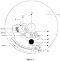
- a sample extraction chip includes a chip body 1 and a sample extraction module provided on the chip body 1.
- the chip body 1 is a flat-shaped object with a predetermined thickness. There are or there are not through-holes, protrusions and recesses provided on the chip body 1.
- the chip body 1 has a rotation center. When the sample extraction chip rotates at a predetermined speed around a rotation axis that passes through the rotation center and is perpendicular to the chip body 1, the liquid in the sample extraction chip can flow, driven by centrifugal force or surface tension or both, from upstream units to downstream units through each flow channel.
- the rotation center may be located inside or outside the sample extraction chip.
- the chip body 1 is circular, and a central hole 101 is provided at the center of the chip body 1 to connect with other components to realize rotation.
- the number of the sample extraction module may be one, two or more. In an embodiment, at least two sample extraction modules are provided, which are sequentially distributed along the rotation direction of the chip body 1.
- the sample extraction module includes a sample-loading lysis unit 2, a liquid release-control unit 4, an extraction unit 6, a liquid switch-control unit 7, a liquid collection unit 8, and a sample collection unit 9 which are connected through flow channels in a sequence of extraction.
- the flow channels are fluid channels, and the fluid includes gas fluid and liquid fluid.
- the sample-loading lysis unit 2 is configured to accommodate and lyse samples.
- the liquid release-control unit 4 is configured to store and release a liquid reagent required for the reaction. The type and category of the reagent may be selected according to actual needs, which is not limited in this application.
- the extraction unit 6 is configured to extract and refine the sample.
- the liquid switch-control unit 7 is configured to switch between communication of the liquid collection unit 8 and the extraction unit 6 as well as communication of the sample collection unit 9 and the extraction unit 6.
- the liquid collection unit 8 is configured to store the waste liquid after the extraction, and the sample collection unit 9 is configured to collect the extracted and refined sample.
- the sample-loading lysis unit 2 and the liquid release-control unit 4 are both located upstream from the extraction unit 6, the liquid switch-control unit 7 is located downstream from the extraction unit 6, and the liquid collection unit 8 and the sample collection unit 9 are both located downstream from the liquid switch-control unit 7.
- the sample extraction chip according to the embodiments realizes integrated and automatic extraction and purification of samples. After manually adding liquid and samples in one step, the biological reaction device according to the embodiments can run with one press with no manual operation during the entire process. This reduces the risk of pathogen infection of operators, avoids cross-contamination between samples, and improves the efficiency of sample preparation, and can promote the standardization, specialization and normalization of clinical sample genetic testing, and improve the level of precision medicine. Moreover, the chip is disposable and only needs to be equipped with a simple centrifugal device, which is compact and portable and low in cost.
- the sample collection unit 9 includes a front collection portion 901 and a rear collection portion 902 which are both in communication with the liquid switch-control unit 7.
- the front collection portion 901 and the rear collection portion 902 are sequentially distributed along the rotation direction of the chip body 1. Samples flow into the front collection portion 901 first, and the into the rear collection portion 902. At least one of the rear collection portions 902 is provided with a sampling port 903.
- the front collection portion 901 and the rear collection portion 902 are referred to as collection portions.
- Each collection portion has only one liquid inlet and is connected to a microchannel of the upstream liquid switch-control unit 7 through the inlet. All the collection portions are sequentially distributed along the rotation direction of the chip body 1.
- the number of the front collection portion 901 and the rear collection portion 902 can be selected and designed according to actual needs.
- the number of the front collection portions 901 may be one, two or more.
- the number of the rear collection portions 902 may be one, two or more.
- one front collection portion 901 and at least two rear collection portions 902 are provided, and each rear collection portion 902 has a sampling port 903.
- the front collection portion 901 may or may not be provided with a sampling port 903, which can be provided as required.
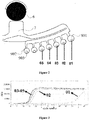
- FIG. 2 seven collection portions in total are provided, one front collection portion 901 and six rear collection portions 902.
- the capacity of the front collection portion 901 is 20 ⁇ L
- the capacity of the rear collection portion 902 is 15 ⁇ L.
- a nucleic acid amplification curve is obtained by performing tests on the front collection portion 901 and the first four rear collection portions 902.
- the front collection portion 901 and the first four rear collection portions 902 are respectively denoted as collection portion 01, collection portion 02, collection portion 03, collection portion 04, and collection portion 05.
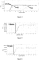
- Figure 3 is the obtained nucleic acid amplification curve.
- Figure 4 is the obtained nucleic acid amplification curve.
- Time positives of the nucleic acid amplification curves of the nucleic acids taken from the five collection portions are significantly different.
- the time positive of the amplification curve of the nucleic acid taken from the collection portion 01 is about 30min to 50min, while the time positive of the amplification curves of the nucleic acids taken from the collection portions 02, 03, 04 and 05 are about 7min to 15min. Therefore, it is suggested that the purity of the nucleic acids taken from the collection portions 02, 03, 04, and 05 is higher than the purity of the nucleic acid taken from the collection portion 01.
- a mixed collection of nucleic acids is realized by using an existing sample extraction chip with Staphylococcus aureus as the sample, and a nucleic acid amplification curve shown in Figure 5 is obtained by amplifying the obtained nucleic acids.
- a segmented collection of nucleic acids is realized by using the sample extraction chip according to this embodiment with the same Staphylococcus aureus as the sample, nucleic acids are extracted from the rear collection portion 902, and a nucleic acid amplification curve shown in Figure 6 is obtained by amplifying the obtained nucleic acids.
- the time positive of the amplification curve in Figure 5 is 18min
- the time positive of the amplification curve in Figure 6 is 13min.
- a mixed collection of nucleic acids is realized by using an existing sample extraction chip with Escherichia coli as the sample, and a nucleic acid amplification curve shown in Figure 7 is obtained by amplifying the obtained nucleic acids.
- a segmented collection of nucleic acids is realized by using the sample extraction chip according to this embodiment with the same Escherichia coli as the sample, nucleic acids are extracted from the rear collection portion 902, and a nucleic acid amplification curve shown in Figure 8 is obtained by amplifying the obtained nucleic acids.
- the time positive of the amplification curve in Figure 7 is 13min
- the time positive of the amplification curve in Figure 6 is 8min.
- the sample collection unit 9 includes the front collection portion 901 and the rear collection portion 902. Since the front collection portion 901 and the rear collection portion 902 are sequentially distributed along the rotation direction of the chip body 1, and the samples flow into the front collection portion 901 first, and then into the rear collection portion 902, the sample in the extraction unit sequentially enters the front collection portion 901 and the rear collection portion 902 from the liquid switch-control unit 7, and the front collection portion 901 collects the front-section sample, and the rear collection portion 902 collects the rear-section sample. Since at least one of the rear collection portion 902 has the sampling port 903, samples can be obtained from the rear collection portion 902 to obtain the rear-section sample.
- the front collection portion 901 and the rear collection portion 902 are both collection portions. In order to ensure that there is a sample in each collection portion, the collection portions are evenly spaced along the rotation direction of the chip body 1.
- the volume of each collection portion can be selected according to actual needs.
- the volume of each of the front collection portion 901 is greater than the volume of each of the rear collection portion 902, as shown in Figure 2 .
- the volume of the front collection portion 901 is 15 ⁇ L to 25 ⁇ L.
- the volume of the front collection portion 901 is 20 ⁇ L
- the volume of the rear collection portion 902 is 15 ⁇ L. It is also applicable that the volume of one certain rear collection portion 902 is greater than the volume of one certain front collection portion 901, which is not limited to the above embodiment.
- the volume size relationship of the collection portions may be other situations.
- the purity of the sample in the last rear collection portion 902 is the highest.
- the last collection portion in the collection portions has the largest volume, that is, the last rear collection portion 902 has the largest volume, as shown in Figure 1 .
- the last rear collection portion 902 refers to the rear collection portion 902 into which the sample finally flows. In this way, the experiment needs can be met.
- the volume of the sample collection unit 9 is the sum of the volumes of the front collection portion 901 and the rear collection portion 902, and the volume of the front collection portion 901 accounts for 20% to 30% of the volume of the sample collection unit 9. Correspondingly, the volume of the rear collection portion 902 accounts for 70% to 80% of the volume of the sample collection unit 9. In order to ensure normal operation, the sum of the volumes of the liquid released and stored by the liquid release-control unit 4 is smaller than the volume of the sample collection unit 9.
- the sampling port 903 needs to be sealed with a sealing member to avoid contamination of the sample.
- the sealing member may be tape, a cover, a plug, or a suction sac.
- the sealing member is preferably selected as the suction sac.
- the suction sac may directly suck out the nucleic acids.
- the suction sac is covered on the sampling port 903. The operation is simple and no additional sampling device is required. It is further ensured that the sample extraction chip is in a completely closed state before or after use, which avoids contamination to the sample extraction chip from itself or the external environment.
- the size and shape of the sampling port 903 can be selected according to actual needs. In order to facilitate sampling, the equivalent diameter of the sampling port 903 is 0.5mm to 10mm.
- the sampling port 903 may be a circle, quasi-circle, rounded rectangle or other polygon. The size and shape of the sampling port 903 are not limited in this embodiment.
- the sample-loading lysis unit 2 mainly includes a sample inlet 201 and a lysis chamber.
- the size and shape of the sample inlet 201 can be selected according to actual needs.
- the sample inlet 201 is a circle or quasi-circle, rounded rectangle or other polygon with an equivalent diameter between 0.5mm and 10mm.
- the sample inlet 201 is a universal sample port, which can be used with various sample-loading devices, and can load and process different clinical samples including sticky sputum, lung lavage fluid, blood, urine, various swabs and difficult-to-handle stools, thereby improving the versatility of the sample extraction chip.
- the sample inlet 201 may be sealed with tape, cover, plug or any other suitable object to avoid contamination.
- the material of the member for sealing the sample inlet 201 may be PC, PS, PP, COC, and COP, which is not limited in this application.
- an opening may be provided on the lysis chamber, the opening extends outside the lysis chamber, and the member for sealing the sample inlet 201 is sleeved on the opening. If it is required that the sample extraction chip shouldn't have too high protrusions, an opening in direct communication with the sample extraction chip may be provided on the lysis chamber, and the member for sealing the sample inlet 201 is directly embedded in the chip body 1, so that the protruding height of the sample extraction chip is the height of the cover of the member for sealing the sample inlet 201.
- the sample-loading lysis unit 2 may adopt various lysis methods such as pyrolysis, chemical lysis, and mechanical lysis, as well as a lysis method of a combination of various methods, such as chemical-assisted mechanical grinding, thermal-assisted mechanical grinding and the like, so that the sample extraction chip can complete nucleic acid preparation for different targets such as fungi, bacteria, and viruses, and thereby the sample extraction chip has strong versatility.
- the lysis chamber may be lateral or longitudinal.
- Reagents and other auxiliary media related to the reaction may be pre-stored in the lysis chamber or be added during use, such as lyophilized powders such as lysis solution and binding buffer solution.
- the reagents may be solid or liquid, and may be in various shapes such as tablet, pellet, powder or paste.
- the auxiliary media may be hard substrates with a diameter of about 0.1mm to 0.5mm, such as glass beads, silicic acid beads, and zirconia beads.
- the lysis chamber may be filled with magnetic hard media with a diameter of about 5mm to 10mm, such as neodymium iron boron magnets, samarium cobalt magnets, alnico magnets and other hard substrates with ferromagnetism.
- magnetic hard media with a diameter of about 5mm to 10mm, such as neodymium iron boron magnets, samarium cobalt magnets, alnico magnets and other hard substrates with ferromagnetism.
- the outlet of the lysis chamber is not at the bottom, and these impurities will not block the flow channel.
- the outlet of the lysis chamber is provided at one-third to one-half of the depth of the lysis chamber to ensure that the residue during the grinding process is deposited at the bottom of the chamber at a high speed.
- the equivalent diameter of an outlet channel 203 of the lysis chamber is 100 ⁇ m to 400 ⁇ m, which prevents broken beads from running out of the lysis chamber to block the flow channel.
- the outlet channel 203 of the lysis chamber is a curved channel pointing to the rotation center, and the height of the curved channel is higher than the height of the liquid level of an adjacent fluid buffer pool 5 to prevent other fluids from entering the lysis chamber.
- the outlet channel 203 of the lysis chamber is provided with a breaking opening, which may be round, square, etc., and the breaking opening may be treated by means of a hydrophobic reagent to ensure that the fluid will not enter the downstream pipeline in advance during sample loading or lysis.
- the breaking opening is a round or square structure on the outlet channel 203. Compared with the outlet channel 203, the breaking opening has a larger width or depth, so that the outlet channel 203 has no siphon force at the breaking opening, thereby preventing the fluid from flowing in the outlet channel 203 due to the siphon force.
- the lysis chamber may be integrated with the chip body 1, or the lysis chamber and the chip body 1 may be different parts combined together.
- the sample-loading lysis unit 2 includes a lysis device 202, and a sample inlet 201 provided on the lysis device 202, the sample inlet 201 is in communication with the lysis device 202, and the lysis device 202 and the chip body 1 are two independent parts.
- the lysis chamber mentioned above is the chamber of the lysis device 202.
- the independent lysis device 202 is directly arranged on the chip body 1, which has the characteristics of high temperature resistance and grinding resistance, and can realize high temperature heating on the chip body 1, avoid the problems of liquid channeling and glue opening at high temperature, and realize the complete integrated functions of nucleic acid preparation.
- the lysis device 202 includes a lysis shell 2023 with ports at two ends, a sealing film 2024 that is connected with the lysis shell 2023 and configured to seal one port, and a sealing cover that is connected with the lysis shell 2023 and configured to seal the other port, and the sealing cover is provided with an opening in communication with the sample inlet 201.
- the sealing cover includes a sealing cover body 2022 and a cap 2021 connected to the sealing cover body 2022.
- the opening in communication with the sample inlet 201 may be provided on the cap 2021.
- the liquid release-control unit 4 is configured to store and release the liquid.
- the liquid includes washing liquid and eluent.
- the liquid may be pre-stored on the chip.
- the storage device may be made of deformable materials such as plastic and aluminum foil, or the storage device may be a reagent loading part processed by substrates such as PMMA, PP, PC, or PS.
- the liquid can be released by extruding.
- a liquid reservoir may be directly provided, and the reagents can be released step-by-step by means of multi-stage capillary channels.
- the liquid release-control unit 4 includes a liquid storage sac 401 and a fixed-position release chamber 402 tightly connected with the liquid storage sac 401.
- the liquid storage sac 401 has a liquid storage cover 4011 that is deformable under pressure and a sealing layer 4012 that is configured to seal the liquid storage cover 4011, the space defined by the sealing layer 4012 and the liquid storage cover 4011 is configured to contain liquid, and the connection strength of a sealing region 4013 between the sealing layer 4012 and the liquid storage cover 4011 is greater than the strength required for rupture of the sealing layer 4012.
- the fixed-position release chamber 402 has a guiding chamber 4021 for collecting liquid and a liquid release site 4022, and when an external force is applied to the liquid storage cover 4011, the liquid release site 4022 only pierces the sealing layer 4012 to cause the liquid storage sac 401 to communicate with the guiding chamber 4021.
- the liquid release-control unit 4 of the above structure When the liquid release-control unit 4 of the above structure is adopted, the liquid is encapsulated in the liquid storage sac 401.
- the liquid storage cover 4011 When the liquid storage cover 4011 is extruded by external force, the liquid in the liquid storage sac 401 is forced to expand and gradually approach the liquid release site 4022.
- the liquid release site 4022 contacts the sealing layer 4012, the liquid release site 4022 pierces the sealing layer 4012, and the liquid storage sac 401 is in communication with the guiding chamber 4021, thereby realizing the full release of the liquid.
- the liquid is stored in the space defined by the liquid storage cover 4011 and the sealing layer 4012.
- the storage of the liquid can be universalized, and compared with the prior art, the method of piercing the sealing layer 4012 to release the liquid has lower requirements for packaging, since the liquid release site is not located on the sealing region 4013.
- the liquid release site is located on the pierced sealing layer 4012, it can ensure that all the liquid is released, thus realizing quantitative release of the liquid after storage and reducing the impact of the inability to quantitatively release on the accuracy of subsequent test.
- the release method of the above-mentioned liquid release-control unit 4 is simple.
- the liquid can be accurately and completely released downstream at a specific position by pressing the liquid storage sac 401, without liquid residue, and quantitative release can be achieved.
- the stability and reliability of the applications can be improved.
- the above-mentioned liquid release-control unit 4 has good sealing effect and small volatilization, which can realize long-term storage of reagents.
- the liquid storage sac 401 and the fixed-position release chamber 402 are tightly connected, and the tight connection is achieved by a connecting layer 403, welding or jigs. Any method that can realize the tight connection between the liquid storage sac 401 and the fixed-position release chamber 402 shall fall within the scope of protection of the present disclosure.
- the shape of the connecting layer 403 is the same as the shape of the sealing layer 4012.
- the connecting layer 403 further plays a role of buffering and protecting the sealing layer 4012.
- the connecting layer 403 completely covers the sealing layer 4012, and the liquid storage sac 401 is connected with the fixed-position release chamber 402 through the connecting layer 403.
- the liquid release site 4022 sequentially pierces the connecting layer 403 and the sealing layer 4012 to release liquid.
- a material missing region 4031 is provided in a portion of the connecting layer 403 corresponding to the guiding groove. That is, a through hole is provided in the portion of the connecting layer 403 corresponding to the guiding groove.
- the material missing region 4031 is circular, semicircular or oval.
- the liquid storage sac 401 is connected with the fixed-position release chamber 402 through the connecting layer 403.
- the connecting layer 403 has the material missing region 4031.
- the connecting layer 403 shields the regions other than the liquid release site 4022. When the liquid storage sac 401 is pressed, the liquid release site 4022 directly contacts the sealing layer 4012, and the sealing layer 4012 is pierced, and other regions are buffered by the connecting layer 403, releasing the liquid.
- the shape of the connecting layer 403 is consistent with the shape of the sealing layer 4012, and the area of the connecting layer 403 is less than, equal to, or greater than the area of the sealing layer 4012.
- the connecting layer 403 completely coincides with the sealing layer 4012, that is, under the premise of same shape, the two have the same areas, and the material missing region 4031 is tangent or partially overlapped with the sealing region 4013 of the sealing layer 4012 at the radially outermost end of the connecting layer 403.
- the liquid storage cover 4011 is in the shape of a bell or an inverted bowl, and the liquid storage cover 4011 is deformable and is able to collapse inward when subjected to a predetermined external pressure. It is also applicable that the liquid storage cover 4011 is in other shapes, which is not limited in this application.
- the liquid release-control unit 4 may be configured as the sealing layer 4012 is able to slightly deform outward when subjected to an internal liquid pressure and to rupture when subjected to a large internal liquid pressure. In this case, there is no need to provide the liquid release site 4022.
- the material of the liquid storage sac 401 has good airtightness, volatility resistance and chemical compatibility for the stored liquid. After the liquid storage sac 401 is sealed, the composition and mass of the stored liquid can be kept relatively stable for a long time.
- the liquid storage cover 4011 is mainly made of a polymer film with a predetermined toughness, and the outer surface of the liquid storage cover may or may not be covered with a layer of metal material.
- the sealing layer 4012 is mainly made of a brittle metal film that is easy to rupture under pressure, and the inner surface of the sealing layer may or may not be covered with a layer of polymer material.
- the main component of the above-mentioned polymer film and polymer material may be PVC, PP, PE, or PET, etc.
- the main component of the metal film and metal material may be aluminum foil or tin foil.
- the volume of the liquid reagent stored in the liquid storage sac 401 accounts for 40% to 100%, preferably 60% to 90%, of the volume of the recess of the liquid storage cover 4011.
- the guiding chamber 4021 is a guiding groove recessed downwardly and provided on the chip body 1, the guiding groove is in communication with a downstream microchannel 102, and the inlet of the guiding groove is completely covered by the sealing layer 4012. This ensures that all the internal channels of the liquid release-control unit 4 are isolated from the outside.
- the volume of the guiding groove is smaller than, equal to or larger than the volume of the liquid storage sac 401, so that the guiding groove can accommodate part or all of the liquid in the liquid storage sac 401.
- the volume of the guiding groove is equal to the volume of the liquid storage sac 401.
- the function of the liquid release site 4022 is to pierce the sealing layer 4012.
- the liquid release site 4022 is directly arranged on the wall of the guiding groove, on the inlet of the guiding groove or in the cavity of the guiding groove.
- the liquid release site 4022 is integrated with the guiding groove or the two are fixed together by bonding or other processes.
- the liquid release site 4022 extends from the wall of the guiding groove to the cavity of the guiding groove, and an end of the liquid release site 4022 corresponds to part of the sealing region 4013 of the sealing layer 4012.
- the shape and size of the liquid release site 4022 can be in arbitrary forms which are convenient for placement or integrated processing, as long as the shape and size can ensure that, the reaction force of the liquid release site 4022 on the sealing layer 4012 can make the sealing layer 4012 rupture, while no leakage or rupture occurs in other positions when the pressure is transmitted downward through the top of the liquid storage sac to the sealing layer 4012 and the sealing region 4013 to cause the sealing layer 4012 to expand downward and be in contact with the liquid release site 4022.
- the distance between the highest point of the liquid release site 4022 and the sealing layer 4012 is not greater than the distance between the upper surface of the chip body 1 and the sealing layer 4012, thereby ensuring that the liquid release site 4022 is not in contact with the sealing layer 4012 when the liquid storage sac 401 is not pressed.
- the edge of the wall of the guiding groove where the liquid release site 4022 is not provided has a rounded structure.
- the liquid release-control unit 4 may be used independently, or multiple liquid release-control units may be used in combination according to requirements, so as to realize the pre-storage of various types of reagents and the sequential release of reagents.
- these liquid release-control units may be arranged in a straight line or in an arbitrary arrangement.
- the liquid release-control units 4 are arranged in a circular array on a circle of equal radius.
- the liquid switch-control unit may be selected as another structure.
- the liquid release-control unit 4 includes:
- the liquid storage chamber 402' is pushed to move toward the chip body 1.
- the sealing film 4021' is in contact with the thorn 403', the thorn 403' pierces the sealing film 4021', and the liquid flows out of the liquid storage chamber and flows into the downstream microchannel 102 through the liquid discharge port 103. Since the liquid release site is on the pierced sealing film 4021', it can be ensured that all the liquid is released, thus realizing quantitative release of the liquid after storage and reducing the impact of the inability to quantitatively release on the accuracy of subsequent test.
- the thorn 403' corresponds to the inner wall of the liquid storage chamber 402'. That is, the position where the thorn 403' pierces the sealing film 4021' is flush with the inner wall of the liquid storage chamber 402', so that there is no sealing film 4021' at the rupture position, thereby reducing the occurrence of dead angles of liquid discharge.
- the thorn 403' is a protrusion with a predetermined hardness and strength and a sharp tip.
- the sliding chamber 401' has a barrel-shaped structure, and the top opening of the sliding chamber 401' has a straight cylindrical structure or an open tapered structure.
- the top opening of the sliding chamber 401' has the open tapered structure. In this way, the liquid storage chamber 402' can be prevented from sliding upward out of the sliding chamber 401'.
- the inner wall of the sliding chamber 401' and the outer wall of the liquid storage chamber 402' are both cylindrical. In addition to sliding up and down in the sliding chamber 401', the liquid storage chamber 402' is able to rotate under the action of external force around the central axis of the cylinder in the sliding chamber 401'.
- the outer wall of the liquid storage chamber 402' is rotatably connected with the inner wall of the sliding chamber 401', or the outer wall of the liquid storage chamber 402' is connected with the inner wall of the sliding chamber 401' through threads.
- a sealing ring is provided between the outer wall of the liquid storage chamber 402' and the inner wall of the sliding chamber 401'.
- the above-mentioned sealing film 4021' may be of a single-layer or multi-layer film.
- the sealing film 4021' may be mainly made of a polymer film, and the outer surface of the sealing film may or may not be covered with a layer of metal material.
- the sealing film may be mainly made of a metal film, and the inner surface of the sealing film may or may not be covered with a layer of polymer material.
- the main component of the polymer film may be PVC, PP, PE, or PET, etc., and the main component of the polymer material may be hot melt adhesive, twin adhesive, or ultraviolet adhesive, etc.
- the main component of the metal film may be aluminum foil, tin foil, etc.
- the liquid release-control unit 4 may be selected as another structure.
- the liquid release-control unit 4 includes a liquid storage chamber and a liquid flow-control unit located downstream from the liquid storage chamber, and the liquid flow-control unit is located between the sample-loading lysis unit 2 and the extraction unit 6.
- the liquid flow-control unit may have various structures.
- the liquid flow-control unit is a capillary channel, an inlet of the capillary channel is closer to the rotation center of the chip body 1 than an outlet of the capillary channel, and a maximum distance from the capillary channel to the surface of the chip body 1 is greater than a distance from the inner wall of the sample-loading lysis unit 2 to the surface of the chip body 1.
- the capillary channel is a curved channel.
- the inlet of the curved channel is in communication with an outlet of an upstream unit or a liquid chamber.
- the outlet of the curved channel is lower than the inlet of the curved channel, that is, the outlet of the curved channel is farther from the rotation center than the inlet of the curved channel.
- the highest point of the curved channel is referred to as the apex of the curved channel, which is higher than the inner wall of the upstream unit or the liquid chamber.
- liquid flow-control unit is a capillary channel
- multiple liquid flow-control units may be connected in series end to end to form a multi-stage flow-control unit.
- the shape and size of the capillary channel may be selected according to actual needs.
- the cross section of the capillary channel may be rectangular, trapezoidal, semicircular, circular or any other shape, and the equivalent diameter of the cross section of the capillary channel is between 0.05mm and 0.5mm.
- the surface of the inner wall or part of the inner wall of the capillary channel is hydrophilic.
- the hydrophilic surface is a sodium dodecyl sulfate layer, a polyethylene glycol octyl phenyl ether layer, an agarose layer, a polyoxyethylene sorbitan fatty acid ester layer or a polypeptide layer. In this way, it is more conducive for the liquid to flow in the capillary channel under the drive of surface tension.
- the equivalent diameters of the capillary channel at different positions may be different.
- a passive blocking pipe section is provided between the inlet of the capillary channel and the apex of the capillary channel, the equivalent diameter of the passive blocking pipe section is greater than the equivalent diameter of the capillary channel, and the surface of the inner wall or part of the inner wall of the passive blocking pipe section is hydrophobic; wherein the apex of the capillary channel is the position where the distance from the capillary channel to the surface of the chip body 1 is the largest.
- the hydrophobic-type surface treatment is performed on the inner wall or part of the inner wall of the passive blocking pipe section.
- the contact angle between the fluid and the processed surface is greater than the contact angle between the fluid and an untreated surface.
- the treated surface is more unfavorable for the liquid to pass through the passive blocking pipe section under the drive of surface tension.
- the above-mentioned liquid flow-control unit may be of other structure.
- the above-mentioned liquid flow-control unit includes a flow control pipeline and a blocked pipeline connected in series with the flow control pipeline, the equivalent diameter of the flow control pipeline is smaller than the equivalent diameter of the blocked pipeline, the blocked pipeline is pre-buried with a hot melt component, and the blocked pipeline is blocked by the hot melt component.
- the blocked pipeline is located at a position close to the outlet of the flow control pipeline, the distance from the blocked pipeline to the outlet of the flow control pipeline is not greater than the length of the blocked pipeline, and a pipeline of the flow control pipeline located between the blocked pipeline and the outlet of the flow control pipeline is consistent with a radial direction of the chip body 1.
- the flow control pipeline may be straight or curve, the cross section of the flow control pipeline may be rectangular, trapezoidal, semicircular, circular or any other shape, and the equivalent diameter of the cross section of the flow control pipeline is between 0.2mm and 2mm.
- the melting point of the hot melt material of the above-mentioned hot-melt component is between 35°C and 100°C.
- the main component of the hot-melt component is paraffin wax or the like.
- the above-mentioned liquid flow-control unit may be of other structure.
- the above-mentioned liquid flow-control unit includes a flow control pipeline and a flow resistance element connected in series with the flow control pipeline, and when the hydraulic pressure in the flow control pipeline is not greater than a preset pressure, the flow resistance element is able to prevent the liquid from passing through the flow control pipeline; when the hydraulic pressure in the flow control pipeline is greater than the preset pressure, the flow resistance element allows the liquid to pass through the flow control pipeline.
- the flow resistance element is a section of slender pipe with an equivalent diameter of less than 0.1mm and a length of more than 3mm.
- the flow resistance element may be a section of pipe filled with porous material.
- the porous material may be a whole or multiple pieces with pores made of filter paper, knitted, or resin material, and the material may be block-shaped, net-shaped, layer-shaped or sponge-shaped.
- the porous material may be formed by dense combination of small particles, and the small particles may be made of resin, ceramic, glass or the like.
- the above-mentioned sample extraction chip further includes a fluid buffer pool 5, which is located upstream from the extraction unit 6 and downstream from the sample-loading lysis unit 2 and the liquid release-control unit 4.
- the fluid buffer pool 5 is able to ensure that the rinsing solution and the eluent do not enter the lysis chamber and the fluid in the lysis chamber does not enter the reagent storage chamber of the liquid release-control unit 4. Moreover, the fluid is easily centrifuged down under the action of centrifugal force.
- the extraction unit 6 includes a fluid chamber and an extraction adsorption component located in the fluid chamber, one fluid chamber is provided, or two fluid chambers are provided, namely an upstream fluid chamber and a downstream fluid chamber, the upstream fluid chamber and the downstream fluid chamber are connected in series, and the extraction adsorption component is filled in the downstream fluid chamber.
- the fluid chamber is a circular chamber with a diameter of 4mm to 8mm.
- the circular chamber can ensure the largest effective area in the smallest radial space, and no liquid will remain in the circular chamber.
- a solid-phase nucleic acid adsorptive substrate used in the extraction absorption component may be a silica substrate, magnetic beads, or anion exchange columns.
- the fluid chamber has at least two upstream fluid inlets and one downstream fluid outlet.
- the upstream fluid chamber has multiple fluid inlets
- the downstream fluid chamber has one fluid outlet.
- the amount of liquid that can be accommodated in the first fluid chamber in the extraction unit 6 is larger than the larger one that can be accommodated in the sample-loading lysis unit 2 and the liquid release-control unit 4.
- the whole or a rear end of fluid chamber filled with the extraction adsorption component is tapered along the flow direction of the fluid. In this way, it is convenient for the extraction adsorption component to adsorb, and the adsorption effect is improved, thereby improving the extraction effect.
- the whole fluid chamber or the rear end thereof has a funnel-shaped structure.
- the extraction adsorption component is made of porous biomacromolecule adsorption material
- the porous biomacromolecule adsorption material is silica fibers or particles or loose membranes, ion exchange resins, silica nanoparticles, magnetic particle materials with silica on the surface, porous materials coated with silica nanomaterials on the surface, porous materials coated with chitosan on the surface, or various other porous materials with silanol modification on the surface.
- the porous biomacromolecule absorption material is loose-film shaped, lamellar or granular, the loose film may be of a single-layer or multi-layer film, and includes layers of different sizes or particles of different sizes.
- the fluid chamber may be filled with porous biomacromolecule adsorption materials of a same kind, or be filled with porous biomacromolecule adsorption materials of different kinds.
- the liquid flow-control unit may be a mechanical valve or a Coriolis-type switch valve for separating the waste liquid and the collection liquid.
- the waste liquid mainly includes lysate and rinsing solution, and the collection liquid is nucleic acid eluent.
- the liquid switch-control unit 7 includes a valve seat 701, a valve core 702, an upstream fluid channel connecting pipe 703, two downstream fluid channel connecting pipes, and a drive component.
- the valve seat 701 includes:
- the first valve core stop position 7013 is arranged between one end of the valve core movement channel 7011 and one of the downstream fluid channel connecting pipes, and the second valve core stop position 7012 is arranged in the valve core movement channel 7011 or between the valve core movement channel 7011 and the other one of the downstream fluid channel connecting pipes.
- the shape of the inner wall at the first valve core stop position 7013 and/or the second valve core stop position 7012 matches with the shape of the outer wall of the valve core 702.
- the two downstream fluid channel connecting pipes respectively are a first downstream fluid channel connecting pipe 704 and a second downstream fluid channel connecting pipe 705.
- first downstream fluid channel connecting pipe 704 when the valve core 702 is at the second valve core stop position 7012, the upstream fluid channel connecting pipe 703 is in communication with the second downstream fluid channel connecting pipe 705.
- second downstream fluid channel connecting pipe 705. As shown in Figure 17 , when the valve core 702 is at the first valve core stop position 7013, the upstream fluid channel connecting pipe 703 is in communication with the first downstream fluid channel connecting pipe 704.
- valve seat 701 is an arc-shaped pipe, and the arc-shaped pipe protrudes toward the rotation center of the chip body 1, the upstream fluid channel connecting pipe 703 is located in the middle of the arc-shaped pipe, and the two downstream fluid channel connecting pipes are respectively located at two ends of the arc-shaped pipe.
- the valve core 702 is made of ferromagnetic material and is spherical.
- the first valve core stop position 7013 and the second valve core stop position 7012 are located at two ends of the arc-shaped pipe, and end portions of the arc-shaped pipe is able to be in close contact with the magnetic ball to seal the liquid outlet.
- the liquid switch-control unit 7 may be of other structure. As shown in Figures 1 and 2 , the liquid switch-control unit 7 includes a deflection cavity with a set size in the radial direction and the normal direction of the chip body 1 and in the direction perpendicular to the chip body 1, an upstream liquid inlet is provided on one side of the deflection cavity close to the rotation center of the chip body 1, two downstream liquid outlets are provided on one side of the deflection cavity away from the rotation center of the chip body 1, and the two downstream liquid outlets are respectively located at two ends of the deflection cavity.
- the switch of communication direction of the liquid switch-control unit 7 is realized by controlling the rotation direction of the chip body 1. For example, when the chip body 1 rotates clockwise, the upstream liquid inlet communicates with one of the downstream liquid outlets; and when the chip body 1 rotates counterclockwise, the upstream liquid inlet communicates with the other one of the downstream liquid outlets.
- the upstream liquid inlet is in communication with the fluid outlet of the extraction unit 6, one of the downstream liquid outlets is connected to the liquid collection unit 8, and the other one of the downstream liquid outlets is connected to the sample collection unit 9.
- the size of the deflection cavity can be selected according to actual needs.
- the size of the deflection cavity in the radial direction is in a range of 1mm to 10mm
- the size in the normal direction is in a range of 1mm to 10mm
- the size in the direction perpendicular to the chip body 1 is in a range of 0.2mm to 5mm.
- the upstream liquid inlet of the deflection cavity is arranged on the inner side of the deflection cavity close to the rotation center, and the size of cross-section of the upstream liquid inlet is in a range of 0.1mm to 1mm.
- the out profile of the deflection cavity has a hillside shape with a higher middle and two lower sides, and the highest point of the hillside shape is not directly above the center of the bottom side of the hillside shape, that is, the hillside shape is asymmetrical.
- the deflection cavity may have other shapes or structures, which is not limited to the above embodiment.
- the contact angle between the inner surface of the deflection cavity and the liquid flowing therethrough is greater than 55 degrees.
- the effect of the contact angle between the inner surface of the deflection cavity and the liquid flowing therethrough is obtained by appropriate chemical treatment on the inner surface of the cavity.
- the liquid collection unit 8 is a C-shaped or inverted C-shaped liquid storage chamber.
- a front end of the liquid storage chamber is provided with a liquid inlet in communication with the upstream, and the volume of the second half of the liquid storage chamber is larger than the sum of the volumes of the liquid that can be released by the sample-loading lysis unit 2 and the liquid release-control unit 4.
- the liquid storage chamber is pre-filled with a liquid-absorbing material, which may be sponge, silicon membrane paper, absorbent cotton, water-absorbing resin particles, dehydrated agarose gel particles, or other water-absorbing agents or porous liquid-absorbing materials.
- a liquid-absorbing material which may be sponge, silicon membrane paper, absorbent cotton, water-absorbing resin particles, dehydrated agarose gel particles, or other water-absorbing agents or porous liquid-absorbing materials.
- the liquid collection unit 8 is in communication with the sample-loading lysis unit 2 and the liquid release-control unit 4 through a thin pipe, which is able to discharge air outside when the liquid located upstream from the liquid collection unit 8 enters the liquid collection unit 8.
- the sample collection unit 9 is connected to an outlet of the liquid switch-control unit 7, and a junction between the sample collection unit 9 and the liquid switch-control unit 7 is able to be connected to one or more liquid release-control units 4 through another thin pipe.
- This thin pipe is able to discharge air outside when the liquid located upstream from the sample collection unit 9 enters the sample collection unit 9.
- a gas pipeline 3 is provided to maintain normal air pressure.
- the gas pipeline 3 includes a waste-liquid-pool gas path and a collection-pool gas path. Under the action of centrifugal force, the airflow in the lysate flows through the extraction unit 6 and returns to the lysis chamber through the waste-liquid-pool gas path; the airflow inside a washing-liquid storage pool also flows through the extraction unit 6 and returns to the washing-liquid storage pool through the waste-liquid-pool gas path; and the airflow inside a eluent storage pool also flows through the extraction unit 6 and returns to the eluent storage pool through the collection-pool gas path.
- the entire path is circulating, which ensures the circulation of internal gas and maintains air pressure balance.
- the washing-liquid storage pool and the eluent storage pool are structures in the liquid release-control unit 4 for storing liquid.
- the above-mentioned sample extraction chip can be used for the nucleic acid preparation from sputum sample.
- the collected sputum mixed sample is added to the lysis device 202 through the sample inlet 201.
- Chemical reagents and lysis medium are pre-stored in the lysis device 202, and magnetic materials are provided at the bottom inside the lysis device 202, which ensures that the lysis medium in the lysis device 202 can be driven to move during rotation. Bacteria in the sputum sample are lysed during the movement. After the lysis is completed, the lysate flows through the extraction unit 6 through the outlet of the lysis device 202 under a predetermined centrifugal force.
- the liquid switch-control unit 7 communicates the extraction unit 6 with the liquid collection unit 8, so that the waste liquid enters the liquid collection unit 8.
- a first-level siphon valve of the liquid release-control unit 4 penetrates through a first-level hydrophobic area and reaches an end of a first-level siphon pipe, and a second-level siphon valve also penetrates through the first-level hydrophobic area and reaches a second-level hydrophobic area.
- the first-level siphon valve releases the washing liquid
- the liquid switch-control unit 7 communicates the extraction unit 6 with the liquid collection unit 8, so that the washing liquid enters the liquid collection unit 8 through the extraction unit 6.
- the second-level siphon valve of the liquid release-control unit 4 penetrates through the second-level hydrophobic area and reaches an end of a second-level siphon pipe.
- the second-level siphon valve releases the eluent, and the liquid switch-control unit 7 communicates the extraction unit 6 with the sample collection unit 9, so that the extracted sample enters the sample collection unit 9 through the extraction unit 6.
- the nucleic acid sample can be taken out for use through the sampling port 903 of the sample collection unit 9.
- internal air pressure balance is achieved through the gas pipeline 3.
- the above-mentioned sample extraction chip can be used for the nucleic acid preparation from sputum/blood sample.
- the pre-processed sputum/blood sample is added to the lysis device 202 through the sample inlet 201.
- Chemical reagents and lysis medium are pre-stored in the lysis device 202, and magnetic materials are provided at the bottom inside the lysis device 202, which ensures that the lysis medium in the lysis device 202 can be driven to move during rotation. Bacteria in the sputum/blood sample are lysed during the movement.
- the liquid switch-control unit 7 is switched to the flow path in communication with the liquid collection unit 8, and the lysate flows through the extraction unit 6 through the outlet of the lysis device 202 and enters the liquid collection unit 8 under a predetermined centrifugal force.
- the washing-liquid storage sac of the liquid release-control unit 4 is mechanically crushed and the washing liquid is released, the liquid switch-control unit 7 is switched to the flow path in communication with the liquid collection unit 8, and the released washing liquid enters the liquid collection unit 8 through the extraction unit 6 under a predetermined centrifugal force.
- the eluent storage sac of the liquid release-control unit 4 is mechanically crushed and the eluent is released, the liquid switch-control unit 7 is switched to the flow path in communication with the sample collection unit 9, and the released eluent enters the sample collection unit 9 through the extraction unit 6 under a predetermined centrifugal force.
- the front-section sample in the front collection portion 901 is discarded, and the rear-section sample in the rear collection portion 902 is collected.
- the nucleic acid sample can be taken out for use through the sampling port 903. In the whole process, internal air pressure balance is achieved through the gas pipeline 3.
- a biological reaction device is further disclosed according to the embodiments, which includes the sample extraction chip according to any one of the above embodiments.
- the biological reaction device Since the sample extraction chip according to the above embodiments has the above technical effects and the biological reaction device has the sample extraction chip, the biological reaction device surely has corresponding technical effects, which will not be repeated here.
Landscapes
- Chemical & Material Sciences (AREA)
- Health & Medical Sciences (AREA)
- Analytical Chemistry (AREA)
- General Health & Medical Sciences (AREA)
- Chemical Kinetics & Catalysis (AREA)
- Dispersion Chemistry (AREA)
- Hematology (AREA)
- Clinical Laboratory Science (AREA)
- Life Sciences & Earth Sciences (AREA)
- Organic Chemistry (AREA)
- Wood Science & Technology (AREA)
- Biochemistry (AREA)
- Zoology (AREA)
- Immunology (AREA)
- Molecular Biology (AREA)
- Physics & Mathematics (AREA)
- Proteomics, Peptides & Aminoacids (AREA)
- Engineering & Computer Science (AREA)
- Microbiology (AREA)
- Biotechnology (AREA)
- Biophysics (AREA)
- Pathology (AREA)
- General Physics & Mathematics (AREA)
- Bioinformatics & Cheminformatics (AREA)
- General Engineering & Computer Science (AREA)
- Genetics & Genomics (AREA)
- Apparatus Associated With Microorganisms And Enzymes (AREA)
- Automatic Analysis And Handling Materials Therefor (AREA)
Abstract
Description
- The present disclosure relates to the technical field of sample extraction, and in particular to a sample extraction chip and a biological reaction device
- Microfluidic chip technology is a technology of integrating basic operation units such as sample preparation, reaction, separation, and detection in biological, chemical or medical analysis processes onto a micron-scale chip to automatically complete the entire analysis process. Specifically, the microfluidic chip can be used for sample extraction, such as nucleic acid extraction.
- Currently, the sample extraction chip has at least two sample extraction modules, and each sample extraction module has a sample collection pool. In the sample extraction module, the extracted samples are all located in a sample collection pool. Affected by various factors, there are impurities in the samples of the sample collection pool, resulting in low purity of the extracted samples, affecting subsequent operations on the samples, and ultimately affecting the test results.
- In summary, a technical issue to be addressed that those skilled in the art desire to achieve is to provide a sample extraction chip to improve the purity of the extracted samples.
- An object of the present disclosure is to provide a sample extraction chip to improve the purity of the extracted samples. Another object of the present disclosure is to provide a biological reaction device with the above sample extraction chip.
- In order to achieve the above objects, the following technical solutions are provided according to the present disclosure.
- A sample extraction chip is provided, which includes a chip body and a sample extraction module provided on the chip body;
where the sample extraction module includes a 2sample-loading lysis unit, a liquid release-control unit, an extraction unit, a liquid switch-control unit, a liquid collection unit and a sample collection unit connected through flow channels in a sequence of extraction;
the liquid release-control unit is configured to store and release liquid reagents, and the liquid switch-control unit is configured to switch between communication of the liquid collection unit and the extraction unit as well as communication of the sample collection unit and the extraction unit; and
the sample collection unit includes a front collection portion and a rear collection portion which are both in communication with the liquid switch-control unit, the front collection portion and the rear collection portion are sequentially distributed along a rotation direction of the chip body, samples flow into the front collection portion first, and then into the rear collection portion, and at least one of the rear collection portion is provided with a sampling port. - Preferably, the front collection portion and the rear collection portion are both collection portions, and the collection portions are evenly spaced along the rotation direction of the chip body.
- Preferably, the front collection portion is provided with the sampling port.
- Preferably, a volume of each of the front collection portion is greater than a volume of each of the rear collection portion, or the last rear collection portion of the front collection portion and the rear collection portion has a largest volume; and
a volume of the sample collection unit is the sum of the volumes of the front collection portion and the rear collection portion, and the volume of the front collection portion accounts for 20% to 30% of the volume of the sample collection unit. - Preferably, the sampling port is sealed by a sealing member, and the sealing member is a suction sac.
- Preferably, the sample-loading lysis unit includes a lysis device and a sample inlet provided on the lysis device, where the sample inlet is in communication with the lysis device, and the lysis device and the chip body are two independent parts.
- Preferably, the lysis device includes
a lysis shell with ports at two ends,
a sealing film that is connected with the lysis shell and configured to seal one port, and
a sealing cover that is connected with the lysis shell and configured to seal the other port,
where the sealing cover is provided with an opening in communication with the sample inlet. - Preferably, the liquid release-control unit includes
a liquid storage sac, and
a fixed-position release chamber tightly connected with the liquid storage sac,
where the liquid storage sac has a liquid storage cover that is deformable under pressure and a sealing layer that is configured to seal the liquid storage cover, the space defined by the sealing layer and the liquid storage cover is configured to contain liquid, and the connection strength of the sealing region between the sealing layer and the liquid storage cover is greater than the strength required for rupture of the sealing layer; and
the fixed-position release chamber has a guiding chamber for collecting liquid and a liquid release site, and when an external force is applied to the liquid storage cover, the liquid release site only pierces the sealing layer to cause the liquid storage sac to communicate with the guiding chamber. - Preferably, the guiding chamber is a guiding groove recessed downwardly and provided on the chip body, the guiding groove is in communication with a downstream microchannel, and the inlet of the guiding groove is completely covered by the sealing layer.
- Preferably, the liquid release site extends from a wall of the guiding groove to a cavity of the guiding groove, and an end of the liquid release site corresponds to part of the sealing region of the sealing layer; and
an edge of the wall of the guiding groove where the liquid release site is not provided has a rounded structure. - Preferably, the liquid release-control unit includes
a sliding chamber provided on the chip body,
a liquid storage chamber provided inside the sliding chamber, and
a thorn provided on the chip body and corresponding to a sealing film,
where the chip body is provided with a liquid discharge port, and the liquid discharge port is in communication with the downstream microchannel;
the liquid storage chamber tightly cooperates with the sliding chamber and is movable toward the chip body, the sealing film is provided at one end of the liquid storage chamber close to the chip body, and a storage cavity for storing liquid is defined by the sealing film and the inner wall of the liquid storage chamber; and
the liquid storage chamber is forced to move to contact with the thorn, the sealing film ruptures. - Preferably, the liquid release-control unit includes a liquid storage chamber and a liquid flow-control unit located downstream from the liquid storage chamber;
where the liquid flow-control unit is located between the sample-loading lysis unit and the extraction unit. - Preferably, the liquid flow-control unit is a capillary channel, an inlet of the capillary channel is closer to a rotation center of the chip body than an outlet of the capillary channel, and a maximum distance from the capillary channel to a surface of the chip body is greater than a distance from the inner wall of the sample-loading lysis unit to the surface of the chip body.
- Preferably, a passive blocking pipe section is provided between the inlet of the capillary channel and the apex of the capillary channel, the equivalent diameter of the passive blocking pipe section is greater than the equivalent diameter of the capillary channel, and the surface of the inner wall or part of the inner wall of the passive blocking pipe section is hydrophobic;
where the apex of the capillary channel is the position where the distance from the capillary channel to the surface of the chip body is the largest. - Preferably, the liquid flow-control unit includes
a flow control pipeline, and
a blocked pipeline connected in series with the flow control pipeline,
where the equivalent diameter of the flow control pipeline is smaller than the equivalent diameter of the blocked pipeline, the blocked pipeline is pre-buried with a hot melt component, and the blocked pipeline is blocked by the hot melt component. - Preferably, the blocked pipeline is located at a position close to the outlet of the flow control pipeline, the distance from the blocked pipeline to the outlet of the flow control pipeline is not greater than a length of the blocked pipeline, and a pipeline of the flow control pipeline located between the blocked pipeline and the outlet of the flow control pipeline is consistent with a radial direction of the chip body.
- Preferably, the liquid flow-control unit includes
a flow control pipeline, and
a flow resistance element connected in series with the flow control pipeline,
where, when hydraulic pressure in the flow control pipeline is not greater than preset pressure, the flow resistance element is configured to prevent the liquid from passing through the flow control pipeline; and when the hydraulic pressure in the flow control pipeline is greater than the preset pressure, the flow resistance element allows the liquid to pass through the flow control pipeline. - Preferably, the extraction unit includes
a fluid chamber, and
an extraction adsorption component located in the fluid chamber,
where, one fluid chamber is provided, or two fluid chambers are provided, namely an upstream fluid chamber and a downstream fluid chamber, the upstream fluid chamber and the downstream fluid chamber are connected in series, and the extraction adsorption component is filled in the downstream fluid chamber. - Preferably, whole or a rear end of the fluid chamber filled with the extraction adsorption component is tapered along the flow direction of the fluid.
- Preferably, the liquid switch-control unit includes
a valve seat,
a valve core,
an upstream fluid channel connecting pipe,
two downstream fluid channel connecting pipes, and
a drive component,
where the valve seat includes a valve core movement channel, a first valve core stop position and a second valve core stop position both of which are in the valve core movement channel;
the upstream fluid channel connecting pipe and the downstream fluid channel connecting pipes are all in communication with the valve core movement channel; and
the driving component is configured to drive the valve core to move by magnetic force, and when the valve core is at the first valve core stop position, the upstream fluid channel connecting pipe is in communication with one of the downstream fluid channel connecting pipes; when the valve core is at the second valve core stop position, the upstream fluid channel connecting pipe is in communication with the other one of the downstream fluid channel connecting pipes. - Preferably, the valve seat is an arc-shaped pipe, and the arc-shaped pipe protrudes toward the rotation center of the chip body, the upstream fluid channel connecting pipe is located in the middle of the arc-shaped pipe, and the two downstream fluid channel connecting pipes are respectively located at two ends of the arc-shaped pipe.
- Preferably, the liquid switch-control unit includes
a deflection cavity with a set size in the radial direction and the normal direction of the chip body and in the direction perpendicular to the chip body,
where an upstream liquid inlet is provided on one side of the deflection cavity close to the rotation center of the chip body, two downstream liquid outlets are provided on one side of the deflection cavity away from the rotation center of the chip body, and the two downstream liquid outlets are respectively located at two ends of the deflection cavity. - Based on the sample extraction chip provided above, a biological reaction device is further disclosed according to the present disclosure, which includes the sample extraction chip according to any one of the above aspects.
- In the sample extraction chip according to the present disclosure, the sample collection unit includes the front collection portion and the rear collection portion. Since the front collection portion and the rear collection portion are sequentially distributed along the rotation direction of the chip body and the samples flow into the front collection portion first, and then into the rear collection portion, the sample in the extraction unit enters the front collection portion and the rear collection portion sequentially from the liquid switch-control unit, the front collection portion collects the front-section sample, and the rear collection portion collects the rear-section sample. Since at least one of the rear collection portion has a sampling port, the sample can be obtained from the rear collection portion to obtain the rear-section sample. Affected by the centrifugal force, most of the impurities in the sample are in the front-section part. Therefore, most of the impurities are in the front collection portion, and there are fewer impurities in the rear collection portion. Therefore, with the sample extraction chip, segmented sample collection is realized, and the rear-section sample can be extracted, thereby effectively improving the purity of the extracted sample.
- For more clearly illustrating embodiments of the present disclosure or the technical solutions in the conventional technology, drawings referred to for describing the embodiments or the conventional technology will be briefly described hereinafter. Apparently, drawings in the following description are only examples of the present disclosure, and for the person skilled in the art, other drawings may be obtained based on the provided drawings without any creative efforts.
-
Figure 1 is a schematic diagram of a sample extraction device according to an embodiment of the present disclosure; -
Figure 2 is a schematic diagram of part of the sample extraction device according to an embodiment of the present disclosure; -
Figure 3 is a comparison diagram of nucleic acid amplification curves of Escherichia coli obtained by using the sample extraction device according to an embodiment of the present disclosure; -
Figure 4 is a comparison diagram of nucleic acid amplification curves of Staphylococcus aureus obtained by using the sample extraction device according to an embodiment of the present disclosure; -
Figure 5 is a diagram of nucleic acid amplification curves of Staphylococcus aureus obtained by using an existing sample extraction device; -
Figure 6 is a diagram of nucleic acid amplification curves of Staphylococcus aureus obtained by using the sample extraction device according to an embodiment of the present disclosure; -
Figure 7 is a diagram of nucleic acid amplification curves of Escherichia coli obtained by using an existing sample extraction device; -
Figure 8 is a diagram of nucleic acid amplification curves of Escherichia coli obtained by using the sample extraction device according to an embodiment of the present disclosure; -
Figure 9 is a schematic diagram showing the structure of a lysis device in the sample extraction device according to an embodiment of the present disclosure; -
Figure 10 is an explodedly schematic diagram of the lysis device in the sample extraction device according to an embodiment of the present disclosure; -
Figure 11 is a schematic diagram showing one structure of a liquid release-control unit in the sample extraction device according to an embodiment of the present disclosure; -
Figure 12 is a sectional view of part of the liquid release-control unit inFigure 11 ; -
Figure 13 is a sectional view of the liquid release-control unit inFigure 11 ; -
Figure 14 is a schematic diagram showing another structure of the liquid release-control unit in the sample extraction device according to an embodiment of the present disclosure; -
Figure 15 is a schematic diagram showing the structure of a liquid switch-control unit in the sample extraction device according to an embodiment of the present disclosure; -
Figure 16 is a schematic diagram showing one communication manner of the liquid switch-control unit in the sample extraction device according to an embodiment of the present disclosure; and -
Figure 17 is a schematic diagram showing another communication manner of the liquid switch-control unit in the sample extraction device according to an embodiment of the present disclosure. - The technical solutions according to the embodiments of the present disclosure will be described clearly and completely as follows in conjunction with the drawings in the embodiments of the present disclosure. It is apparent that the described embodiments are only a part of the embodiments according to the present disclosure, rather than all the embodiments. Any other embodiments obtained by those skilled in the art based on the embodiments of the present disclosure without any creative work fall within the protection scope of the present disclosure.
- As shown in
Figures 1 and2 , a sample extraction chip according to an embodiment of the present disclosure includes achip body 1 and a sample extraction module provided on thechip body 1. - The
chip body 1 is a flat-shaped object with a predetermined thickness. There are or there are not through-holes, protrusions and recesses provided on thechip body 1. Thechip body 1 has a rotation center. When the sample extraction chip rotates at a predetermined speed around a rotation axis that passes through the rotation center and is perpendicular to thechip body 1, the liquid in the sample extraction chip can flow, driven by centrifugal force or surface tension or both, from upstream units to downstream units through each flow channel. - The rotation center may be located inside or outside the sample extraction chip. In an embodiment, the
chip body 1 is circular, and acentral hole 101 is provided at the center of thechip body 1 to connect with other components to realize rotation. - The number of the sample extraction module may be one, two or more. In an embodiment, at least two sample extraction modules are provided, which are sequentially distributed along the rotation direction of the
chip body 1. - The sample extraction module includes a sample-
loading lysis unit 2, a liquid release-control unit 4, anextraction unit 6, a liquid switch-control unit 7, aliquid collection unit 8, and asample collection unit 9 which are connected through flow channels in a sequence of extraction. The flow channels are fluid channels, and the fluid includes gas fluid and liquid fluid. - The sample-
loading lysis unit 2 is configured to accommodate and lyse samples. The liquid release-control unit 4 is configured to store and release a liquid reagent required for the reaction. The type and category of the reagent may be selected according to actual needs, which is not limited in this application. Theextraction unit 6 is configured to extract and refine the sample. The liquid switch-control unit 7 is configured to switch between communication of theliquid collection unit 8 and theextraction unit 6 as well as communication of thesample collection unit 9 and theextraction unit 6. Theliquid collection unit 8 is configured to store the waste liquid after the extraction, and thesample collection unit 9 is configured to collect the extracted and refined sample. - The sample-
loading lysis unit 2 and the liquid release-control unit 4 are both located upstream from theextraction unit 6, the liquid switch-control unit 7 is located downstream from theextraction unit 6, and theliquid collection unit 8 and thesample collection unit 9 are both located downstream from the liquid switch-control unit 7. - The sample extraction chip according to the embodiments realizes integrated and automatic extraction and purification of samples. After manually adding liquid and samples in one step, the biological reaction device according to the embodiments can run with one press with no manual operation during the entire process. This reduces the risk of pathogen infection of operators, avoids cross-contamination between samples, and improves the efficiency of sample preparation, and can promote the standardization, specialization and normalization of clinical sample genetic testing, and improve the level of precision medicine. Moreover, the chip is disposable and only needs to be equipped with a simple centrifugal device, which is compact and portable and low in cost.
- In order to improve the purity of the extracted sample, the
sample collection unit 9 includes afront collection portion 901 and arear collection portion 902 which are both in communication with the liquid switch-control unit 7. Thefront collection portion 901 and therear collection portion 902 are sequentially distributed along the rotation direction of thechip body 1. Samples flow into thefront collection portion 901 first, and the into therear collection portion 902. At least one of therear collection portions 902 is provided with asampling port 903. - For convenience, the
front collection portion 901 and therear collection portion 902 are referred to as collection portions. Each collection portion has only one liquid inlet and is connected to a microchannel of the upstream liquid switch-control unit 7 through the inlet. All the collection portions are sequentially distributed along the rotation direction of thechip body 1. The number of thefront collection portion 901 and therear collection portion 902 can be selected and designed according to actual needs. The number of thefront collection portions 901 may be one, two or more. The number of therear collection portions 902 may be one, two or more. In an embodiment, onefront collection portion 901 and at least tworear collection portions 902 are provided, and eachrear collection portion 902 has asampling port 903. - The
front collection portion 901 may or may not be provided with asampling port 903, which can be provided as required. - Referring to
Figure 2 , seven collection portions in total are provided, onefront collection portion 901 and sixrear collection portions 902. The capacity of thefront collection portion 901 is 20µL, and the capacity of therear collection portion 902 is 15µL. A nucleic acid amplification curve is obtained by performing tests on thefront collection portion 901 and the first fourrear collection portions 902. Thefront collection portion 901 and the first fourrear collection portions 902 are respectively denoted ascollection portion 01,collection portion 02,collection portion 03,collection portion 04, andcollection portion 05. - Taking Escherichia coli as the sample,
Figure 3 is the obtained nucleic acid amplification curve. Taking Staphylococcus aureus as the sample,Figure 4 is the obtained nucleic acid amplification curve. Time positives of the nucleic acid amplification curves of the nucleic acids taken from the five collection portions are significantly different. The time positive of the amplification curve of the nucleic acid taken from thecollection portion 01 is about 30min to 50min, while the time positive of the amplification curves of the nucleic acids taken from thecollection portions collection portions collection portion 01. - Therefore, in the actual application process, it is preferred to sample from the
rear collection portion 902, so that the purity of the obtained sample is higher. - A mixed collection of nucleic acids is realized by using an existing sample extraction chip with Staphylococcus aureus as the sample, and a nucleic acid amplification curve shown in
Figure 5 is obtained by amplifying the obtained nucleic acids. A segmented collection of nucleic acids is realized by using the sample extraction chip according to this embodiment with the same Staphylococcus aureus as the sample, nucleic acids are extracted from therear collection portion 902, and a nucleic acid amplification curve shown inFigure 6 is obtained by amplifying the obtained nucleic acids. The time positive of the amplification curve inFigure 5 is 18min, and the time positive of the amplification curve inFigure 6 is 13min. By comparingFigure 5 withFigure 6 , it is suggested that all the time positives of the nucleic acid amplification of the nucleic acids obtained from therear collection portion 902 are about 5min earlier than the time positive of the mixed collection, and the nucleic acid amplification efficiency is improved by at least 10 times. - A mixed collection of nucleic acids is realized by using an existing sample extraction chip with Escherichia coli as the sample, and a nucleic acid amplification curve shown in
Figure 7 is obtained by amplifying the obtained nucleic acids. A segmented collection of nucleic acids is realized by using the sample extraction chip according to this embodiment with the same Escherichia coli as the sample, nucleic acids are extracted from therear collection portion 902, and a nucleic acid amplification curve shown inFigure 8 is obtained by amplifying the obtained nucleic acids. The time positive of the amplification curve inFigure 7 is 13min, and the time positive of the amplification curve inFigure 6 is 8min. By comparingFigure 7 withFigure 8 , it is suggested that all the time positives of the nucleic acid amplification of the nucleic acids obtained from therear collection portion 902 are about 5min earlier than the time positive of the mixed collection, and the nucleic acid amplification efficiency is improved by at least 10 times. - In the sample extraction chip according to the above embodiment, the
sample collection unit 9 includes thefront collection portion 901 and therear collection portion 902. Since thefront collection portion 901 and therear collection portion 902 are sequentially distributed along the rotation direction of thechip body 1, and the samples flow into thefront collection portion 901 first, and then into therear collection portion 902, the sample in the extraction unit sequentially enters thefront collection portion 901 and therear collection portion 902 from the liquid switch-control unit 7, and thefront collection portion 901 collects the front-section sample, and therear collection portion 902 collects the rear-section sample. Since at least one of therear collection portion 902 has thesampling port 903, samples can be obtained from therear collection portion 902 to obtain the rear-section sample. Affected by the centrifugal force, most of the impurities in the sample are in the front-section part. Most of the impurities are in thefront collection portion 901, and there are fewer impurities in therear collection portion 902. Therefore, with the sample extraction chip, segmented sample collection is realized, and the rear-section sample can be extracted, thereby effectively improving the purity of the extracted samples. - In the above sample extraction chip, the
front collection portion 901 and therear collection portion 902 are both collection portions. In order to ensure that there is a sample in each collection portion, the collection portions are evenly spaced along the rotation direction of thechip body 1. - The volume of each collection portion can be selected according to actual needs. In an embodiment, the volume of each of the
front collection portion 901 is greater than the volume of each of therear collection portion 902, as shown inFigure 2 . For example, the volume of thefront collection portion 901 is 15µL to 25µL. Further, the volume of thefront collection portion 901 is 20µL, and the volume of therear collection portion 902 is 15µL. It is also applicable that the volume of one certainrear collection portion 902 is greater than the volume of one certainfront collection portion 901, which is not limited to the above embodiment. - It is also applicable that the volume size relationship of the collection portions may be other situations. In the actual application process, the purity of the sample in the last
rear collection portion 902 is the highest. For experiments that require a large quantity of the samples, it is preferred that the last collection portion in the collection portions has the largest volume, that is, the lastrear collection portion 902 has the largest volume, as shown inFigure 1 . It should be noted that the lastrear collection portion 902 refers to therear collection portion 902 into which the sample finally flows. In this way, the experiment needs can be met. - The volume of the
sample collection unit 9 is the sum of the volumes of thefront collection portion 901 and therear collection portion 902, and the volume of thefront collection portion 901 accounts for 20% to 30% of the volume of thesample collection unit 9. Correspondingly, the volume of therear collection portion 902 accounts for 70% to 80% of the volume of thesample collection unit 9. In order to ensure normal operation, the sum of the volumes of the liquid released and stored by the liquid release-control unit 4 is smaller than the volume of thesample collection unit 9. - In the above sample extraction chip, the
sampling port 903 needs to be sealed with a sealing member to avoid contamination of the sample. The sealing member may be tape, a cover, a plug, or a suction sac. In order to facilitate the sealing and extraction, the sealing member is preferably selected as the suction sac. In this way, after the nucleic acid preparation is completed, the suction sac may directly suck out the nucleic acids. After the suction operation is completed, the suction sac is covered on thesampling port 903. The operation is simple and no additional sampling device is required. It is further ensured that the sample extraction chip is in a completely closed state before or after use, which avoids contamination to the sample extraction chip from itself or the external environment. - The size and shape of the
sampling port 903 can be selected according to actual needs. In order to facilitate sampling, the equivalent diameter of thesampling port 903 is 0.5mm to 10mm. Thesampling port 903 may be a circle, quasi-circle, rounded rectangle or other polygon. The size and shape of thesampling port 903 are not limited in this embodiment. - The sample-
loading lysis unit 2 mainly includes asample inlet 201 and a lysis chamber. - The size and shape of the
sample inlet 201 can be selected according to actual needs. For example, thesample inlet 201 is a circle or quasi-circle, rounded rectangle or other polygon with an equivalent diameter between 0.5mm and 10mm. In order to improve the versatility, thesample inlet 201 is a universal sample port, which can be used with various sample-loading devices, and can load and process different clinical samples including sticky sputum, lung lavage fluid, blood, urine, various swabs and difficult-to-handle stools, thereby improving the versatility of the sample extraction chip. - The
sample inlet 201 may be sealed with tape, cover, plug or any other suitable object to avoid contamination. The material of the member for sealing thesample inlet 201 may be PC, PS, PP, COC, and COP, which is not limited in this application. - In the actual application process, an opening may be provided on the lysis chamber, the opening extends outside the lysis chamber, and the member for sealing the
sample inlet 201 is sleeved on the opening. If it is required that the sample extraction chip shouldn't have too high protrusions, an opening in direct communication with the sample extraction chip may be provided on the lysis chamber, and the member for sealing thesample inlet 201 is directly embedded in thechip body 1, so that the protruding height of the sample extraction chip is the height of the cover of the member for sealing thesample inlet 201. - The sample-
loading lysis unit 2 may adopt various lysis methods such as pyrolysis, chemical lysis, and mechanical lysis, as well as a lysis method of a combination of various methods, such as chemical-assisted mechanical grinding, thermal-assisted mechanical grinding and the like, so that the sample extraction chip can complete nucleic acid preparation for different targets such as fungi, bacteria, and viruses, and thereby the sample extraction chip has strong versatility. - The lysis chamber may be lateral or longitudinal. Reagents and other auxiliary media related to the reaction may be pre-stored in the lysis chamber or be added during use, such as lyophilized powders such as lysis solution and binding buffer solution. The reagents may be solid or liquid, and may be in various shapes such as tablet, pellet, powder or paste. The auxiliary media may be hard substrates with a diameter of about 0.1mm to 0.5mm, such as glass beads, silicic acid beads, and zirconia beads. In addition, the lysis chamber may be filled with magnetic hard media with a diameter of about 5mm to 10mm, such as neodymium iron boron magnets, samarium cobalt magnets, alnico magnets and other hard substrates with ferromagnetism.
- Some large particles of impurities quickly reach the bottom of the lysis chamber by centrifugation. Therefore, the outlet of the lysis chamber is not at the bottom, and these impurities will not block the flow channel. The outlet of the lysis chamber is provided at one-third to one-half of the depth of the lysis chamber to ensure that the residue during the grinding process is deposited at the bottom of the chamber at a high speed. The equivalent diameter of an
outlet channel 203 of the lysis chamber is 100µm to 400µm, which prevents broken beads from running out of the lysis chamber to block the flow channel. Preferably, theoutlet channel 203 of the lysis chamber is a curved channel pointing to the rotation center, and the height of the curved channel is higher than the height of the liquid level of an adjacentfluid buffer pool 5 to prevent other fluids from entering the lysis chamber. - The
outlet channel 203 of the lysis chamber is provided with a breaking opening, which may be round, square, etc., and the breaking opening may be treated by means of a hydrophobic reagent to ensure that the fluid will not enter the downstream pipeline in advance during sample loading or lysis. The breaking opening is a round or square structure on theoutlet channel 203. Compared with theoutlet channel 203, the breaking opening has a larger width or depth, so that theoutlet channel 203 has no siphon force at the breaking opening, thereby preventing the fluid from flowing in theoutlet channel 203 due to the siphon force. - The lysis chamber may be integrated with the
chip body 1, or the lysis chamber and thechip body 1 may be different parts combined together. In an embodiment, the sample-loading lysis unit 2 includes alysis device 202, and asample inlet 201 provided on thelysis device 202, thesample inlet 201 is in communication with thelysis device 202, and thelysis device 202 and thechip body 1 are two independent parts. It should be noted that the lysis chamber mentioned above is the chamber of thelysis device 202. - In the above structure, the
independent lysis device 202 is directly arranged on thechip body 1, which has the characteristics of high temperature resistance and grinding resistance, and can realize high temperature heating on thechip body 1, avoid the problems of liquid channeling and glue opening at high temperature, and realize the complete integrated functions of nucleic acid preparation. - In an embodiment, as shown in
Figures 9 and10 , thelysis device 202 includes alysis shell 2023 with ports at two ends, asealing film 2024 that is connected with thelysis shell 2023 and configured to seal one port, and a sealing cover that is connected with thelysis shell 2023 and configured to seal the other port, and the sealing cover is provided with an opening in communication with thesample inlet 201. - Further, the sealing cover includes a sealing
cover body 2022 and acap 2021 connected to the sealingcover body 2022. The opening in communication with thesample inlet 201 may be provided on thecap 2021. - The liquid release-
control unit 4 is configured to store and release the liquid. The liquid includes washing liquid and eluent. For ease of use, the liquid may be pre-stored on the chip. The storage device may be made of deformable materials such as plastic and aluminum foil, or the storage device may be a reagent loading part processed by substrates such as PMMA, PP, PC, or PS. The liquid can be released by extruding. For simplifying the difficulty of chip processing, a liquid reservoir may be directly provided, and the reagents can be released step-by-step by means of multi-stage capillary channels. - As shown in
Figures 11 to 13 , the liquid release-control unit 4 includes aliquid storage sac 401 and a fixed-position release chamber 402 tightly connected with theliquid storage sac 401. - The
liquid storage sac 401 has aliquid storage cover 4011 that is deformable under pressure and asealing layer 4012 that is configured to seal theliquid storage cover 4011, the space defined by thesealing layer 4012 and theliquid storage cover 4011 is configured to contain liquid, and the connection strength of asealing region 4013 between thesealing layer 4012 and theliquid storage cover 4011 is greater than the strength required for rupture of thesealing layer 4012. - The fixed-
position release chamber 402 has a guidingchamber 4021 for collecting liquid and aliquid release site 4022, and when an external force is applied to theliquid storage cover 4011, theliquid release site 4022 only pierces thesealing layer 4012 to cause theliquid storage sac 401 to communicate with the guidingchamber 4021. - When the liquid release-
control unit 4 of the above structure is adopted, the liquid is encapsulated in theliquid storage sac 401. When theliquid storage cover 4011 is extruded by external force, the liquid in theliquid storage sac 401 is forced to expand and gradually approach theliquid release site 4022. When theliquid release site 4022 contacts thesealing layer 4012, theliquid release site 4022 pierces thesealing layer 4012, and theliquid storage sac 401 is in communication with the guidingchamber 4021, thereby realizing the full release of the liquid. - It can be seen that, in the above process, the liquid is stored in the space defined by the
liquid storage cover 4011 and thesealing layer 4012. The storage of the liquid can be universalized, and compared with the prior art, the method of piercing thesealing layer 4012 to release the liquid has lower requirements for packaging, since the liquid release site is not located on thesealing region 4013. Moreover, since the liquid release site is located on thepierced sealing layer 4012, it can ensure that all the liquid is released, thus realizing quantitative release of the liquid after storage and reducing the impact of the inability to quantitatively release on the accuracy of subsequent test. - The release method of the above-mentioned liquid release-
control unit 4 is simple. The liquid can be accurately and completely released downstream at a specific position by pressing theliquid storage sac 401, without liquid residue, and quantitative release can be achieved. Especially for applications of releasing multiple liquids in sequence, the stability and reliability of the applications can be improved. - The above-mentioned liquid release-
control unit 4 has good sealing effect and small volatilization, which can realize long-term storage of reagents. - The
liquid storage sac 401 and the fixed-position release chamber 402 are tightly connected, and the tight connection is achieved by a connectinglayer 403, welding or jigs. Any method that can realize the tight connection between theliquid storage sac 401 and the fixed-position release chamber 402 shall fall within the scope of protection of the present disclosure. - The shape of the connecting
layer 403 is the same as the shape of thesealing layer 4012. In addition to the function of connecting theliquid storage sac 401 with the fixed-position release chamber 402, the connectinglayer 403 further plays a role of buffering and protecting thesealing layer 4012. The connectinglayer 403 completely covers thesealing layer 4012, and theliquid storage sac 401 is connected with the fixed-position release chamber 402 through the connectinglayer 403. When theliquid storage sac 401 is pressed, theliquid release site 4022 sequentially pierces the connectinglayer 403 and thesealing layer 4012 to release liquid. - Alternatively, a
material missing region 4031 is provided in a portion of the connectinglayer 403 corresponding to the guiding groove. That is, a through hole is provided in the portion of the connectinglayer 403 corresponding to the guiding groove. Thematerial missing region 4031 is circular, semicircular or oval. Theliquid storage sac 401 is connected with the fixed-position release chamber 402 through the connectinglayer 403. The connectinglayer 403 has thematerial missing region 4031. The connectinglayer 403 shields the regions other than theliquid release site 4022. When theliquid storage sac 401 is pressed, theliquid release site 4022 directly contacts thesealing layer 4012, and thesealing layer 4012 is pierced, and other regions are buffered by the connectinglayer 403, releasing the liquid. - The shape of the connecting
layer 403 is consistent with the shape of thesealing layer 4012, and the area of the connectinglayer 403 is less than, equal to, or greater than the area of thesealing layer 4012. When the connectinglayer 403 completely coincides with thesealing layer 4012, that is, under the premise of same shape, the two have the same areas, and thematerial missing region 4031 is tangent or partially overlapped with thesealing region 4013 of thesealing layer 4012 at the radially outermost end of the connectinglayer 403. - In an embodiment, the
liquid storage cover 4011 is in the shape of a bell or an inverted bowl, and theliquid storage cover 4011 is deformable and is able to collapse inward when subjected to a predetermined external pressure. It is also applicable that theliquid storage cover 4011 is in other shapes, which is not limited in this application. - The liquid release-
control unit 4 may be configured as thesealing layer 4012 is able to slightly deform outward when subjected to an internal liquid pressure and to rupture when subjected to a large internal liquid pressure. In this case, there is no need to provide theliquid release site 4022. - The material of the
liquid storage sac 401 has good airtightness, volatility resistance and chemical compatibility for the stored liquid. After theliquid storage sac 401 is sealed, the composition and mass of the stored liquid can be kept relatively stable for a long time. In particular, theliquid storage cover 4011 is mainly made of a polymer film with a predetermined toughness, and the outer surface of the liquid storage cover may or may not be covered with a layer of metal material. Thesealing layer 4012 is mainly made of a brittle metal film that is easy to rupture under pressure, and the inner surface of the sealing layer may or may not be covered with a layer of polymer material. - The main component of the above-mentioned polymer film and polymer material may be PVC, PP, PE, or PET, etc., and the main component of the metal film and metal material may be aluminum foil or tin foil.
- The volume of the liquid reagent stored in the
liquid storage sac 401 accounts for 40% to 100%, preferably 60% to 90%, of the volume of the recess of theliquid storage cover 4011. - In an embodiment, the guiding
chamber 4021 is a guiding groove recessed downwardly and provided on thechip body 1, the guiding groove is in communication with adownstream microchannel 102, and the inlet of the guiding groove is completely covered by thesealing layer 4012. This ensures that all the internal channels of the liquid release-control unit 4 are isolated from the outside. - The volume of the guiding groove is smaller than, equal to or larger than the volume of the
liquid storage sac 401, so that the guiding groove can accommodate part or all of the liquid in theliquid storage sac 401. Preferably, the volume of the guiding groove is equal to the volume of theliquid storage sac 401. - The function of the
liquid release site 4022 is to pierce thesealing layer 4012. Theliquid release site 4022 is directly arranged on the wall of the guiding groove, on the inlet of the guiding groove or in the cavity of the guiding groove. Theliquid release site 4022 is integrated with the guiding groove or the two are fixed together by bonding or other processes. In a case that theliquid release site 4022 is integrated with the guiding groove, theliquid release site 4022 extends from the wall of the guiding groove to the cavity of the guiding groove, and an end of theliquid release site 4022 corresponds to part of thesealing region 4013 of thesealing layer 4012. The shape and size of theliquid release site 4022 can be in arbitrary forms which are convenient for placement or integrated processing, as long as the shape and size can ensure that, the reaction force of theliquid release site 4022 on thesealing layer 4012 can make thesealing layer 4012 rupture, while no leakage or rupture occurs in other positions when the pressure is transmitted downward through the top of the liquid storage sac to thesealing layer 4012 and thesealing region 4013 to cause thesealing layer 4012 to expand downward and be in contact with theliquid release site 4022. The distance between the highest point of theliquid release site 4022 and thesealing layer 4012 is not greater than the distance between the upper surface of thechip body 1 and thesealing layer 4012, thereby ensuring that theliquid release site 4022 is not in contact with thesealing layer 4012 when theliquid storage sac 401 is not pressed. - In order to ensure that there is only one reliable
liquid release site 4022 on the guiding groove, the edge of the wall of the guiding groove where theliquid release site 4022 is not provided has a rounded structure. - In a case that the above-mentioned liquid release-
control unit 4 is used in the sample extraction chip, the liquid release-control unit 4 may be used independently, or multiple liquid release-control units may be used in combination according to requirements, so as to realize the pre-storage of various types of reagents and the sequential release of reagents. In a case that multiple liquid release-control units 4 are used in combination, these liquid release-control units may be arranged in a straight line or in an arbitrary arrangement. In order to balance the system, it is preferred that the liquid release-control units 4 are arranged in a circular array on a circle of equal radius. - In the above-mentioned sample extraction chip, the liquid switch-control unit may be selected as another structure. As shown in
Figure 14 , the liquid release-control unit 4 includes: - a sliding chamber 401' provided on the
chip body 1, - a liquid storage chamber 402' provided inside the sliding chamber 401', and
- a thorn 403' provided on the
chip body 1 and corresponding to the sealing film 4021', - and the
chip body 1 is provided with aliquid discharge port 103, and theliquid discharge port 103 is in communication with thedownstream microchannel 102; - the liquid storage chamber 402' tightly cooperates with the sliding chamber 401' and is movable toward the
chip body 1, a sealing film 4021' is provided at one end of the liquid storage chamber 402' close to thechip body 1, and a storage cavity 4022' for storing liquid is defined by the sealing film 4021' and the inner wall of the liquid storage chamber 402'; and - when the liquid storage chamber 402' is forced to move to contact with the thorn 403', the sealing film 4021' ruptures.
- In a case that the above-mentioned liquid release-
control unit 4 is used, the liquid storage chamber 402' is pushed to move toward thechip body 1. When the sealing film 4021' is in contact with the thorn 403', the thorn 403' pierces the sealing film 4021', and the liquid flows out of the liquid storage chamber and flows into thedownstream microchannel 102 through theliquid discharge port 103. Since the liquid release site is on the pierced sealing film 4021', it can be ensured that all the liquid is released, thus realizing quantitative release of the liquid after storage and reducing the impact of the inability to quantitatively release on the accuracy of subsequent test. - In order to reduce the dead angle of liquid discharge, in this embodiment, the thorn 403' corresponds to the inner wall of the liquid storage chamber 402'. That is, the position where the thorn 403' pierces the sealing film 4021' is flush with the inner wall of the liquid storage chamber 402', so that there is no sealing film 4021' at the rupture position, thereby reducing the occurrence of dead angles of liquid discharge.
- The thorn 403' is a protrusion with a predetermined hardness and strength and a sharp tip.
- The sliding chamber 401' has a barrel-shaped structure, and the top opening of the sliding chamber 401' has a straight cylindrical structure or an open tapered structure.
- Preferably, the top opening of the sliding chamber 401' has the open tapered structure. In this way, the liquid storage chamber 402' can be prevented from sliding upward out of the sliding chamber 401'.
- The inner wall of the sliding chamber 401' and the outer wall of the liquid storage chamber 402' are both cylindrical. In addition to sliding up and down in the sliding chamber 401', the liquid storage chamber 402' is able to rotate under the action of external force around the central axis of the cylinder in the sliding chamber 401'.
- The outer wall of the liquid storage chamber 402' is rotatably connected with the inner wall of the sliding chamber 401', or the outer wall of the liquid storage chamber 402' is connected with the inner wall of the sliding chamber 401' through threads. In a case that the outer wall of the liquid storage chamber 402' is rotatably connected with the inner wall of the sliding chamber 401', a sealing ring is provided between the outer wall of the liquid storage chamber 402' and the inner wall of the sliding chamber 401'.
- The above-mentioned sealing film 4021' may be of a single-layer or multi-layer film. The sealing film 4021' may be mainly made of a polymer film, and the outer surface of the sealing film may or may not be covered with a layer of metal material. The sealing film may be mainly made of a metal film, and the inner surface of the sealing film may or may not be covered with a layer of polymer material. The main component of the polymer film may be PVC, PP, PE, or PET, etc., and the main component of the polymer material may be hot melt adhesive, twin adhesive, or ultraviolet adhesive, etc. The main component of the metal film may be aluminum foil, tin foil, etc.
- In the above-mentioned sample extraction chip, the liquid release-
control unit 4 may be selected as another structure. The liquid release-control unit 4 includes a liquid storage chamber and a liquid flow-control unit located downstream from the liquid storage chamber, and the liquid flow-control unit is located between the sample-loading lysis unit 2 and theextraction unit 6. - The liquid flow-control unit may have various structures. The liquid flow-control unit is a capillary channel, an inlet of the capillary channel is closer to the rotation center of the
chip body 1 than an outlet of the capillary channel, and a maximum distance from the capillary channel to the surface of thechip body 1 is greater than a distance from the inner wall of the sample-loading lysis unit 2 to the surface of thechip body 1. - The capillary channel is a curved channel. The inlet of the curved channel is in communication with an outlet of an upstream unit or a liquid chamber. The outlet of the curved channel is lower than the inlet of the curved channel, that is, the outlet of the curved channel is farther from the rotation center than the inlet of the curved channel. The highest point of the curved channel is referred to as the apex of the curved channel, which is higher than the inner wall of the upstream unit or the liquid chamber.
- In a case that the above-mentioned liquid flow-control unit is a capillary channel, multiple liquid flow-control units may be connected in series end to end to form a multi-stage flow-control unit.
- The shape and size of the capillary channel may be selected according to actual needs. The cross section of the capillary channel may be rectangular, trapezoidal, semicircular, circular or any other shape, and the equivalent diameter of the cross section of the capillary channel is between 0.05mm and 0.5mm.
- The surface of the inner wall or part of the inner wall of the capillary channel is hydrophilic. The hydrophilic surface is a sodium dodecyl sulfate layer, a polyethylene glycol octyl phenyl ether layer, an agarose layer, a polyoxyethylene sorbitan fatty acid ester layer or a polypeptide layer. In this way, it is more conducive for the liquid to flow in the capillary channel under the drive of surface tension.
- The equivalent diameters of the capillary channel at different positions may be different. Preferably, a passive blocking pipe section is provided between the inlet of the capillary channel and the apex of the capillary channel, the equivalent diameter of the passive blocking pipe section is greater than the equivalent diameter of the capillary channel, and the surface of the inner wall or part of the inner wall of the passive blocking pipe section is hydrophobic; wherein the apex of the capillary channel is the position where the distance from the capillary channel to the surface of the
chip body 1 is the largest. - The hydrophobic-type surface treatment is performed on the inner wall or part of the inner wall of the passive blocking pipe section. For the liquid to pass through the passive blocking pipe section, the contact angle between the fluid and the processed surface is greater than the contact angle between the fluid and an untreated surface. The treated surface is more unfavorable for the liquid to pass through the passive blocking pipe section under the drive of surface tension.
- The above-mentioned liquid flow-control unit may be of other structure. The above-mentioned liquid flow-control unit includes a flow control pipeline and a blocked pipeline connected in series with the flow control pipeline, the equivalent diameter of the flow control pipeline is smaller than the equivalent diameter of the blocked pipeline, the blocked pipeline is pre-buried with a hot melt component, and the blocked pipeline is blocked by the hot melt component.
- Preferably, the blocked pipeline is located at a position close to the outlet of the flow control pipeline, the distance from the blocked pipeline to the outlet of the flow control pipeline is not greater than the length of the blocked pipeline, and a pipeline of the flow control pipeline located between the blocked pipeline and the outlet of the flow control pipeline is consistent with a radial direction of the
chip body 1. - The flow control pipeline may be straight or curve, the cross section of the flow control pipeline may be rectangular, trapezoidal, semicircular, circular or any other shape, and the equivalent diameter of the cross section of the flow control pipeline is between 0.2mm and 2mm.
- The melting point of the hot melt material of the above-mentioned hot-melt component is between 35°C and 100°C. The main component of the hot-melt component is paraffin wax or the like.
- The above-mentioned liquid flow-control unit may be of other structure. The above-mentioned liquid flow-control unit includes a flow control pipeline and a flow resistance element connected in series with the flow control pipeline, and when the hydraulic pressure in the flow control pipeline is not greater than a preset pressure, the flow resistance element is able to prevent the liquid from passing through the flow control pipeline; when the hydraulic pressure in the flow control pipeline is greater than the preset pressure, the flow resistance element allows the liquid to pass through the flow control pipeline.
- The flow resistance element is a section of slender pipe with an equivalent diameter of less than 0.1mm and a length of more than 3mm.
- The flow resistance element may be a section of pipe filled with porous material. The porous material may be a whole or multiple pieces with pores made of filter paper, knitted, or resin material, and the material may be block-shaped, net-shaped, layer-shaped or sponge-shaped. The porous material may be formed by dense combination of small particles, and the small particles may be made of resin, ceramic, glass or the like.
- The above-mentioned sample extraction chip further includes a
fluid buffer pool 5, which is located upstream from theextraction unit 6 and downstream from the sample-loading lysis unit 2 and the liquid release-control unit 4. - The
fluid buffer pool 5 is able to ensure that the rinsing solution and the eluent do not enter the lysis chamber and the fluid in the lysis chamber does not enter the reagent storage chamber of the liquid release-control unit 4. Moreover, the fluid is easily centrifuged down under the action of centrifugal force. - In the above-mentioned sample extraction chip, the
extraction unit 6 includes a fluid chamber and an extraction adsorption component located in the fluid chamber, one fluid chamber is provided, or two fluid chambers are provided, namely an upstream fluid chamber and a downstream fluid chamber, the upstream fluid chamber and the downstream fluid chamber are connected in series, and the extraction adsorption component is filled in the downstream fluid chamber. - Preferably, the fluid chamber is a circular chamber with a diameter of 4mm to 8mm. The circular chamber can ensure the largest effective area in the smallest radial space, and no liquid will remain in the circular chamber. A solid-phase nucleic acid adsorptive substrate used in the extraction absorption component may be a silica substrate, magnetic beads, or anion exchange columns.
- The fluid chamber has at least two upstream fluid inlets and one downstream fluid outlet. In a case that two fluid chambers are provided, the upstream fluid chamber has multiple fluid inlets, and the downstream fluid chamber has one fluid outlet.
- The amount of liquid that can be accommodated in the first fluid chamber in the
extraction unit 6 is larger than the larger one that can be accommodated in the sample-loading lysis unit 2 and the liquid release-control unit 4. - Furthermore, the whole or a rear end of fluid chamber filled with the extraction adsorption component is tapered along the flow direction of the fluid. In this way, it is convenient for the extraction adsorption component to adsorb, and the adsorption effect is improved, thereby improving the extraction effect. The whole fluid chamber or the rear end thereof has a funnel-shaped structure.
- The extraction adsorption component is made of porous biomacromolecule adsorption material, and the porous biomacromolecule adsorption material is silica fibers or particles or loose membranes, ion exchange resins, silica nanoparticles, magnetic particle materials with silica on the surface, porous materials coated with silica nanomaterials on the surface, porous materials coated with chitosan on the surface, or various other porous materials with silanol modification on the surface.
- The porous biomacromolecule absorption material is loose-film shaped, lamellar or granular, the loose film may be of a single-layer or multi-layer film, and includes layers of different sizes or particles of different sizes. The fluid chamber may be filled with porous biomacromolecule adsorption materials of a same kind, or be filled with porous biomacromolecule adsorption materials of different kinds.
- In the above-mentioned sample extraction chip, the liquid flow-control unit may be a mechanical valve or a Coriolis-type switch valve for separating the waste liquid and the collection liquid. The waste liquid mainly includes lysate and rinsing solution, and the collection liquid is nucleic acid eluent.
- Preferably, as shown in
Figures 15 and 17 , the liquid switch-control unit 7 includes avalve seat 701, avalve core 702, an upstream fluidchannel connecting pipe 703, two downstream fluid channel connecting pipes, and a drive component. - The
valve seat 701 includes: - a valve
core movement channel 7011, and - a first valve
core stop position 7013 and a second valvecore stop position 7012 both of which are in the valvecore movement channel 7011, - the upstream fluid
channel connecting pipe 703 and the downstream fluid channel connecting pipes are all in communication with the valvecore movement channel 7011, the driving component is configured to drive thevalve core 702 to move by magnetic force, - when the
valve core 702 is at the first valvecore stop position 7013, the upstream fluidchannel connecting pipe 703 is in communication with one of the downstream fluid channel connecting pipes; and - when the
valve core 702 is at the second valvecore stop position 7012, the upstream fluidchannel connecting pipe 703 is in communication with the other one of the downstream fluid channel connecting pipes. - One of the downstream fluid channel connecting pipes in communication with the
liquid collection unit 8, and the other one of the downstream fluid channel connecting pipes is in communication with thesample collection unit 9. - The first valve
core stop position 7013 is arranged between one end of the valvecore movement channel 7011 and one of the downstream fluid channel connecting pipes, and the second valvecore stop position 7012 is arranged in the valvecore movement channel 7011 or between the valvecore movement channel 7011 and the other one of the downstream fluid channel connecting pipes. The shape of the inner wall at the first valvecore stop position 7013 and/or the second valvecore stop position 7012 matches with the shape of the outer wall of thevalve core 702. - The two downstream fluid channel connecting pipes respectively are a first downstream fluid
channel connecting pipe 704 and a second downstream fluidchannel connecting pipe 705. As shown inFigure 16 , when thevalve core 702 is at the second valvecore stop position 7012, the upstream fluidchannel connecting pipe 703 is in communication with the second downstream fluidchannel connecting pipe 705. As shown inFigure 17 , when thevalve core 702 is at the first valvecore stop position 7013, the upstream fluidchannel connecting pipe 703 is in communication with the first downstream fluidchannel connecting pipe 704. - Furthermore, the above-mentioned
valve seat 701 is an arc-shaped pipe, and the arc-shaped pipe protrudes toward the rotation center of thechip body 1, the upstream fluidchannel connecting pipe 703 is located in the middle of the arc-shaped pipe, and the two downstream fluid channel connecting pipes are respectively located at two ends of the arc-shaped pipe. - The
valve core 702 is made of ferromagnetic material and is spherical. The first valvecore stop position 7013 and the second valvecore stop position 7012 are located at two ends of the arc-shaped pipe, and end portions of the arc-shaped pipe is able to be in close contact with the magnetic ball to seal the liquid outlet. - In the above-mentioned sample extraction chip, the liquid switch-
control unit 7 may be of other structure. As shown inFigures 1 and2 , the liquid switch-control unit 7 includes a deflection cavity with a set size in the radial direction and the normal direction of thechip body 1 and in the direction perpendicular to thechip body 1, an upstream liquid inlet is provided on one side of the deflection cavity close to the rotation center of thechip body 1, two downstream liquid outlets are provided on one side of the deflection cavity away from the rotation center of thechip body 1, and the two downstream liquid outlets are respectively located at two ends of the deflection cavity. - In the above structure, the switch of communication direction of the liquid switch-
control unit 7 is realized by controlling the rotation direction of thechip body 1. For example, when thechip body 1 rotates clockwise, the upstream liquid inlet communicates with one of the downstream liquid outlets; and when thechip body 1 rotates counterclockwise, the upstream liquid inlet communicates with the other one of the downstream liquid outlets. - It can be understood that, the upstream liquid inlet is in communication with the fluid outlet of the
extraction unit 6, one of the downstream liquid outlets is connected to theliquid collection unit 8, and the other one of the downstream liquid outlets is connected to thesample collection unit 9. - The size of the deflection cavity can be selected according to actual needs. Preferably, the size of the deflection cavity in the radial direction is in a range of 1mm to 10mm, the size in the normal direction is in a range of 1mm to 10mm, and the size in the direction perpendicular to the
chip body 1 is in a range of 0.2mm to 5mm. - The upstream liquid inlet of the deflection cavity is arranged on the inner side of the deflection cavity close to the rotation center, and the size of cross-section of the upstream liquid inlet is in a range of 0.1mm to 1mm. The out profile of the deflection cavity has a hillside shape with a higher middle and two lower sides, and the highest point of the hillside shape is not directly above the center of the bottom side of the hillside shape, that is, the hillside shape is asymmetrical.
- The deflection cavity may have other shapes or structures, which is not limited to the above embodiment.
- In order to more easily achieve the function of the deflection cavity, it is preferred that the contact angle between the inner surface of the deflection cavity and the liquid flowing therethrough is greater than 55 degrees. The effect of the contact angle between the inner surface of the deflection cavity and the liquid flowing therethrough is obtained by appropriate chemical treatment on the inner surface of the cavity.
- In the above-mentioned sample extraction chip, the
liquid collection unit 8 is a C-shaped or inverted C-shaped liquid storage chamber. A front end of the liquid storage chamber is provided with a liquid inlet in communication with the upstream, and the volume of the second half of the liquid storage chamber is larger than the sum of the volumes of the liquid that can be released by the sample-loading lysis unit 2 and the liquid release-control unit 4. - The liquid storage chamber is pre-filled with a liquid-absorbing material, which may be sponge, silicon membrane paper, absorbent cotton, water-absorbing resin particles, dehydrated agarose gel particles, or other water-absorbing agents or porous liquid-absorbing materials.
- The
liquid collection unit 8 is in communication with the sample-loading lysis unit 2 and the liquid release-control unit 4 through a thin pipe, which is able to discharge air outside when the liquid located upstream from theliquid collection unit 8 enters theliquid collection unit 8. - In the above-mentioned sample extraction chip, the
sample collection unit 9 is connected to an outlet of the liquid switch-control unit 7, and a junction between thesample collection unit 9 and the liquid switch-control unit 7 is able to be connected to one or more liquid release-control units 4 through another thin pipe. This thin pipe is able to discharge air outside when the liquid located upstream from thesample collection unit 9 enters thesample collection unit 9. - In the above-mentioned sample extraction chip, a
gas pipeline 3 is provided to maintain normal air pressure. Thegas pipeline 3 includes a waste-liquid-pool gas path and a collection-pool gas path. Under the action of centrifugal force, the airflow in the lysate flows through theextraction unit 6 and returns to the lysis chamber through the waste-liquid-pool gas path; the airflow inside a washing-liquid storage pool also flows through theextraction unit 6 and returns to the washing-liquid storage pool through the waste-liquid-pool gas path; and the airflow inside a eluent storage pool also flows through theextraction unit 6 and returns to the eluent storage pool through the collection-pool gas path. The entire path is circulating, which ensures the circulation of internal gas and maintains air pressure balance. - The washing-liquid storage pool and the eluent storage pool are structures in the liquid release-
control unit 4 for storing liquid. - In order to more specifically describe the sample extraction chip according to this disclosure, two specific embodiments are provided below.
- The above-mentioned sample extraction chip can be used for the nucleic acid preparation from sputum sample. The collected sputum mixed sample is added to the
lysis device 202 through thesample inlet 201. Chemical reagents and lysis medium are pre-stored in thelysis device 202, and magnetic materials are provided at the bottom inside thelysis device 202, which ensures that the lysis medium in thelysis device 202 can be driven to move during rotation. Bacteria in the sputum sample are lysed during the movement. After the lysis is completed, the lysate flows through theextraction unit 6 through the outlet of thelysis device 202 under a predetermined centrifugal force. The liquid switch-control unit 7 communicates theextraction unit 6 with theliquid collection unit 8, so that the waste liquid enters theliquid collection unit 8. At this time, a first-level siphon valve of the liquid release-control unit 4 penetrates through a first-level hydrophobic area and reaches an end of a first-level siphon pipe, and a second-level siphon valve also penetrates through the first-level hydrophobic area and reaches a second-level hydrophobic area. Under a predetermined centrifugal force, the first-level siphon valve releases the washing liquid, and the liquid switch-control unit 7 communicates theextraction unit 6 with theliquid collection unit 8, so that the washing liquid enters theliquid collection unit 8 through theextraction unit 6. At this time, the second-level siphon valve of the liquid release-control unit 4 penetrates through the second-level hydrophobic area and reaches an end of a second-level siphon pipe. Under a predetermined centrifugal force, the second-level siphon valve releases the eluent, and the liquid switch-control unit 7 communicates theextraction unit 6 with thesample collection unit 9, so that the extracted sample enters thesample collection unit 9 through theextraction unit 6. Then, the nucleic acid sample can be taken out for use through thesampling port 903 of thesample collection unit 9. In the whole process, internal air pressure balance is achieved through thegas pipeline 3. - The above-mentioned sample extraction chip can be used for the nucleic acid preparation from sputum/blood sample. The pre-processed sputum/blood sample is added to the
lysis device 202 through thesample inlet 201. Chemical reagents and lysis medium are pre-stored in thelysis device 202, and magnetic materials are provided at the bottom inside thelysis device 202, which ensures that the lysis medium in thelysis device 202 can be driven to move during rotation. Bacteria in the sputum/blood sample are lysed during the movement. After the lysis is completed, the liquid switch-control unit 7 is switched to the flow path in communication with theliquid collection unit 8, and the lysate flows through theextraction unit 6 through the outlet of thelysis device 202 and enters theliquid collection unit 8 under a predetermined centrifugal force. At this time, the washing-liquid storage sac of the liquid release-control unit 4 is mechanically crushed and the washing liquid is released, the liquid switch-control unit 7 is switched to the flow path in communication with theliquid collection unit 8, and the released washing liquid enters theliquid collection unit 8 through theextraction unit 6 under a predetermined centrifugal force. Then, the eluent storage sac of the liquid release-control unit 4 is mechanically crushed and the eluent is released, the liquid switch-control unit 7 is switched to the flow path in communication with thesample collection unit 9, and the released eluent enters thesample collection unit 9 through theextraction unit 6 under a predetermined centrifugal force. The front-section sample in thefront collection portion 901 is discarded, and the rear-section sample in therear collection portion 902 is collected. Then, the nucleic acid sample can be taken out for use through thesampling port 903. In the whole process, internal air pressure balance is achieved through thegas pipeline 3. - Based on the sample extraction chip according to the above embodiments, a biological reaction device is further disclosed according to the embodiments, which includes the sample extraction chip according to any one of the above embodiments.
- Since the sample extraction chip according to the above embodiments has the above technical effects and the biological reaction device has the sample extraction chip, the biological reaction device surely has corresponding technical effects, which will not be repeated here.
Claims (15)
- A sample extraction chip, comprising:a chip body (1) ; anda sample extraction module provided on the chip body (1);wherein the sample extraction module comprises a sample-loading lysis unit (2), a liquid release-control unit (4), an extraction unit (6), a liquid switch-control unit (7), a liquid collection unit (8) and a sample collection unit (9), which are connected through flow channels in a sequence of extraction;the liquid release-control unit (4) is configured to store and release liquid reagents, and the liquid switch-control unit (7) is configured to switch between communication of the liquid collection unit (8) and the extraction unit (6) as well as communication of the sample collection unit (9) and the extraction unit (6); andthe sample collection unit (9) comprises a front collection portion (901) and a rear collection portion (902) which are both in communication with the liquid switch-control unit (7), the front collection portion (901) and the rear collection portion (902) are sequentially distributed along a rotation direction of the chip body (1), samples flow into the front collection portion (901) first, and then into the rear collection portion (902), and at least one of the rear collection portion (902) is provided with a sampling port (903).
- The sample extraction chip according to claim 1, wherein the front collection portion (901) and the rear collection portion (902) are both collection portions, and the collection portions are evenly spaced along the rotation direction of the chip body (1).
- The sample extraction chip according to claim 1, wherein the front collection portion (901) is provided with the sampling port (903).
- The sample extraction chip according to claim 1, wherein a volume of each of the front collection portion (901) is greater than a volume of each of the rear collection portion (902), or the last rear collection portion (902) of the front collection portion (901) and the rear collection portion (902) has a largest volume; and
a volume of the sample collection unit (9) is a sum of the volumes of the front collection portion (901) and the rear collection portion (902), and the volume of the front collection portion (901) accounts for 20% to 30% of the volume of the sample collection unit (9). - The sample extraction chip according to claim 1, wherein the sampling port (903) is sealed by a sealing member, and the sealing member is a suction sac.
- The sample extraction chip according to claim 1, wherein
the sample-loading lysis unit (2) comprises a lysis device (202), and a sample inlet (201) provided on the lysis device (202),
wherein the sample inlet (201) is in communication with the lysis device (202), and the lysis device (202) and the chip body (1) are two independent parts; and
the lysis device (202) comprises:a lysis shell (2023) with ports at two ends,a sealing film (2024) that is connected with the lysis shell (2023) and configured to seal one port, anda sealing cover that is connected with the lysis shell (2023) and configured to seal the other port,wherein the sealing cover is provided with an opening in communication with the sample inlet (201). - The sample extraction chip according to claim 1, wherein the liquid release-control unit (4) comprises
a liquid storage sac (401), and
a fixed-position release chamber (402) tightly connected with the liquid storage sac (401),
wherein the liquid storage sac (401) has a liquid storage cover (4011) that is deformable under pressure and a sealing layer (4012) that is configured to seal the liquid storage cover (4011), a space defined by the sealing layer (4012) and the liquid storage cover (4011) is configured to contain liquid, and a connection strength of a sealing region (4013) between the sealing layer (4012) and the liquid storage cover (4011) is greater than a strength for rupture of the sealing layer (4012); and
the fixed-position release chamber (402) has a guiding chamber (4021) for collecting liquid and a liquid release site (4022), and when an external force is applied to the liquid storage cover (4011), and the liquid release site (4022) only pierces the sealing layer (4012) to cause the liquid storage sac (401) to communicate with the guiding chamber (4021); and
wherein the guiding chamber (4021) is a guiding groove recessed downwardly and provided on the chip body (1), the guiding groove is in communication with a downstream microchannel (102), and an inlet of the guiding groove is completely covered by the sealing layer (4012); and
wherein the liquid release site (4022) extends from a wall of the guiding groove to a cavity of the guiding groove, and an end of the liquid release site (4022) corresponds to part of the sealing region (4013) of the sealing layer (4012); and
an edge of the wall of the guiding groove where the liquid release site (4022) is not provided has a rounded structure. - The sample extraction chip according to claim 1, wherein the liquid release-control unit (4) comprises:a sliding chamber (401') provided on the chip body (1),a liquid storage chamber (402') provided inside the sliding chamber (401'), anda thorn (403') provided on the chip body (1) and corresponding to a sealing film (4021'),wherein the chip body (1) is provided with a liquid discharge port (103), and the liquid discharge port (103) is in communication with the downstream microchannel (102);the liquid storage chamber (402') tightly cooperates with the sliding chamber (401') and is movable toward the chip body (1), the sealing film (4021') is provided at one end of the liquid storage chamber (402') close to the chip body (1), and a storage cavity (4022') for storing liquid is defined by the sealing film (4021') and an inner wall of the liquid storage chamber (402'); andwhen the liquid storage chamber (402') is forced to move to contact with the thorn (403'), the sealing film (4021') ruptures.
- The sample extraction chip according to claim 1, wherein the liquid release-control unit (4) comprises a liquid storage chamber and a liquid flow-control unit located downstream from the liquid storage chamber,
wherein the liquid flow-control unit is located between the sample-loading lysis unit (2) and the extraction unit (6). - The sample extraction chip according to claim 9, wherein
the liquid flow-control unit is a capillary channel, an inlet of the capillary channel is closer to a rotation center of the chip body (1) than an outlet of the capillary channel, and a maximum distance from the capillary channel to a surface of the chip body (1) is greater than a distance from an inner wall of the sample-loading lysis unit (2) to the surface of the chip body (1); wherein
a passive blocking pipe section is provided between the inlet of the capillary channel and an apex of the capillary channel, an equivalent diameter of the passive blocking pipe section is greater than an equivalent diameter of the capillary channel, and a surface of the inner wall or part of the inner wall of the passive blocking pipe section is hydrophobic;
wherein the apex of the capillary channel is a position where a distance from the capillary channel to the surface of the chip body (1) is the largest. - The sample extraction chip according to claim 9, wherein
the liquid flow-control unit comprises a flow control pipeline and a blocked pipeline connected in series with the flow control pipeline,
wherein the equivalent diameter of the flow control pipeline is smaller than the equivalent diameter of the blocked pipeline, the blocked pipeline is pre-buried with a hot melt component, and the blocked pipeline is blocked by the hot melt component; and
the blocked pipeline is located at a position close to an outlet of the flow control pipeline, a distance from the blocked pipeline to the outlet of the flow control pipeline is not greater than a length of the blocked pipeline, and a pipeline of the flow control pipeline located between the blocked pipeline and the outlet of the flow control pipeline is consistent with a radial direction of the chip body (1);
or,
the liquid flow-control unit comprises a flow control pipeline and a flow resistance element connected in series with the flow control pipeline,
wherein, when hydraulic pressure in the flow control pipeline is not greater than preset pressure, the flow resistance element is configured to prevent the liquid from passing through the flow control pipeline; and when the hydraulic pressure in the flow control pipeline is greater than the preset pressure, the flow resistance element allows the liquid to pass through the flow control pipeline. - The sample extraction chip according to claim 1, wherein
the extraction unit (6) comprises a fluid chamber and an extraction adsorption component located in the fluid chamber,
wherein, one fluid chamber is provided, or two fluid chambers are provided, namely an upstream fluid chamber and a downstream fluid chamber, the upstream fluid chamber and the downstream fluid chamber are connected in series, and the extraction adsorption component is filled in the downstream fluid chamber; and
whole or a rear end of the fluid chamber filled with the extraction adsorption component or is tapered along a flow direction of the fluid. - The sample extraction chip according to claim 1, wherein
the liquid switch-control unit (7) comprises a valve seat (701), a valve core (702), an upstream fluid channel connecting pipe (703), two downstream fluid channel connecting pipes, and a drive component,
wherein the valve seat (701) comprises a valve core movement channel (7011), a first valve core stop position (7013) and a second valve core stop position (7012) both of which are in the valve core movement channel (7011);
the upstream fluid channel connecting pipe (703) and the downstream fluid channel connecting pipes are all in communication with the valve core movement channel (7011); and
the driving component is configured to drive the valve core (702) to move by magnetic force, and when the valve core (702) is at the first valve core stop position (7013), the upstream fluid channel connecting pipe (703) is in communication with one of the downstream fluid channel connecting pipes; and when the valve core (702) is at the second valve core stop position (702), the upstream fluid channel connecting pipe (703) is in communication with the other one of the downstream fluid channel connecting pipes; and wherein
the valve seat (701) is an arc-shaped pipe, and the arc-shaped pipe protrudes toward the rotation center of the chip body (1), the upstream fluid channel connecting pipe (703) is located in middle of the arc-shaped pipe, and the two downstream fluid channel connecting pipes are respectively located at two ends of the arc-shaped pipe. - The sample extraction chip according to claim 1, wherein
the liquid switch-control unit (7) comprises a deflection cavity with a set size in a radial direction and a normal direction of the chip body (1) and in a direction perpendicular to the chip body (1),
wherein an upstream liquid inlet is provided on one side of the deflection cavity close to the rotation center of the chip body (1), two downstream liquid outlets are provided on one side of the deflection cavity away from the rotation center of the chip body (1), and the two downstream liquid outlets are respectively located at two ends of the deflection cavity. - A biological reaction device, comprising the sample extraction chip according to any one of claims 1 to 14.
Applications Claiming Priority (1)
| Application Number | Priority Date | Filing Date | Title |
|---|---|---|---|
| CN202010308397.6A CN111205966B (en) | 2020-04-18 | 2020-04-18 | Sample extraction chips and bioreactors |
Publications (2)
| Publication Number | Publication Date |
|---|---|
| EP3895800A2 true EP3895800A2 (en) | 2021-10-20 |
| EP3895800A3 EP3895800A3 (en) | 2021-10-27 |
Family
ID=70783585
Family Applications (1)
| Application Number | Title | Priority Date | Filing Date |
|---|---|---|---|
| EP20214852.4A Pending EP3895800A3 (en) | 2020-04-18 | 2020-12-17 | Sample extraction chip and biological reaction device |
Country Status (3)
| Country | Link |
|---|---|
| US (1) | US11666911B2 (en) |
| EP (1) | EP3895800A3 (en) |
| CN (1) | CN111205966B (en) |
Families Citing this family (10)
| Publication number | Priority date | Publication date | Assignee | Title |
|---|---|---|---|---|
| WO2022213630A1 (en) * | 2021-04-08 | 2022-10-13 | 埃妥生物科技(杭州)有限公司 | Sample extractor and sample extraction method |
| CN114100711B (en) * | 2021-11-17 | 2022-11-29 | 江苏液滴逻辑生物技术有限公司 | Packaging, pre-embedding and sample injection device and method for chip reagent and application |
| CN113913289B (en) * | 2021-12-07 | 2022-03-22 | 北京芯源视界生物科技有限公司 | Detection kit and detection method for pathogenic nucleic acid under airtight condition |
| CN114768896B (en) * | 2022-03-11 | 2023-12-29 | 南方科技大学 | Centrifugal microfluidic chip integrating whole blood separation and molecular diagnosis and preparation method |
| CN114574347B (en) * | 2022-05-09 | 2022-07-05 | 博奥生物集团有限公司 | A multi-index detection device and its multi-index detection chip and using method |
| CN115074230B (en) * | 2022-07-21 | 2023-05-23 | 北京泰豪生物科技有限公司 | Reagent controlled release module, bioreactor and biological detection device |
| CN115970787A (en) * | 2022-12-17 | 2023-04-18 | 武汉科技大学 | Diabetes sample protector |
| CN117088001A (en) * | 2023-07-14 | 2023-11-21 | 广州国家实验室 | A reagent bag, base assembly and automatic sample adding device |
| WO2025050373A1 (en) * | 2023-09-08 | 2025-03-13 | 深圳华大智造科技股份有限公司 | Reaction module, sample preparation system, sample preparation method, and biochemical substance analysis system |
| CN117309501B (en) * | 2023-11-29 | 2024-01-30 | 德州润泓五金机电设备有限公司 | A kind of water quality analysis equipment in water conservancy projects |
Family Cites Families (19)
| Publication number | Priority date | Publication date | Assignee | Title |
|---|---|---|---|---|
| GB0129816D0 (en) | 2001-12-13 | 2002-01-30 | The Technology Partnership Plc | Testing device for chemical or biochemical analysis |
| JP2008525791A (en) | 2004-12-28 | 2008-07-17 | 松下電器産業株式会社 | Device for testing and blood mixture dilution method |
| EP2135069A4 (en) | 2007-03-02 | 2011-03-09 | Univ Laval | IN SERIES LIFTING VALVES FOR FLUIDIC OR MICROFLUIDIC DEVICES |
| KR101258434B1 (en) | 2007-05-03 | 2013-05-02 | 삼성전자주식회사 | Microfluidic system and fabricating method of the same |
| JP6200419B2 (en) | 2011-06-03 | 2017-09-20 | ラディセンス ダイアグノスティクス リミテッド | Microfluidic disc for use in bead-based immunoassays |
| DE102012205523A1 (en) | 2012-04-04 | 2013-10-10 | Robert Bosch Gmbh | Reagent vessel insert and reagent vessel |
| US10130947B2 (en) | 2012-12-05 | 2018-11-20 | Radisens Diagnostics Limited | Valving system for use in centrifugal microfluidic platforms |
| CN103203258B (en) * | 2013-03-27 | 2015-01-14 | 清华大学 | Micro-fluidic chip for droplet extraction |
| EP2994543B1 (en) | 2013-05-07 | 2018-08-15 | Micronics, Inc. | Device for preparation and analysis of nucleic acids |
| AU2014357716A1 (en) | 2013-09-18 | 2016-04-07 | California Institute Of Technology | System and method for movement and timing control |
| DE102015218665A1 (en) | 2015-09-29 | 2017-03-30 | Robert Bosch Gmbh | Apparatus and method for storing and emptying fluid-filled containers in microfluidic devices |
| CN105316224B (en) | 2015-12-07 | 2017-10-27 | 中国科学院苏州生物医学工程技术研究所 | Full-automatic nucleic acid extraction expands micro-fluidic chip and its application process with PCR |
| US20200008299A1 (en) * | 2016-10-21 | 2020-01-02 | Bao Tran | Flexible printed electronics |
| CN107557285B (en) * | 2017-09-05 | 2021-04-27 | 吉林大学 | A microfluidic device for realizing low-voltage electrolytic cell lysis and a method for lysing cells |
| CN107893026A (en) * | 2017-12-29 | 2018-04-10 | 苏州绘真医学检验所有限公司 | Detect micro-fluidic chip, detection method and the detecting system of human virus' nucleic acid |
| CN109456882A (en) * | 2019-01-16 | 2019-03-12 | 北京理工大学 | A kind of space biological sample micro process integrating device |
| CN209923319U (en) | 2019-04-18 | 2020-01-10 | 深圳市刚竹医疗科技有限公司 | Microfluidic chip structure and analysis device |
| CN110029052A (en) * | 2019-04-18 | 2019-07-19 | 深圳市刚竹医疗科技有限公司 | Micro-fluidic chip and analysis system |
| CN110441108B (en) * | 2019-08-16 | 2024-05-07 | 华南理工大学 | A disc chip device and method suitable for blood sample pretreatment |
-
2020
- 2020-04-18 CN CN202010308397.6A patent/CN111205966B/en active Active
- 2020-12-14 US US17/121,337 patent/US11666911B2/en active Active
- 2020-12-17 EP EP20214852.4A patent/EP3895800A3/en active Pending
Also Published As
| Publication number | Publication date |
|---|---|
| EP3895800A3 (en) | 2021-10-27 |
| US11666911B2 (en) | 2023-06-06 |
| US20210322982A1 (en) | 2021-10-21 |
| CN111205966B (en) | 2020-07-21 |
| CN111205966A (en) | 2020-05-29 |
Similar Documents
| Publication | Publication Date | Title |
|---|---|---|
| US11666911B2 (en) | Sample extraction chip and biological reaction device | |
| US12544755B2 (en) | Whole-process biological detection device | |
| US12017222B2 (en) | Analysis unit for a transportable microfluidic device, in particular for sample preparation and molecule analysis | |
| CN111760601B (en) | Microfluidic chip of integrated liquid path switching valve and nucleic acid detection method | |
| US10625258B2 (en) | Microfluidic size-exclusion devices, systems, and methods | |
| CN115703993B (en) | Microfluidic chip, nucleic acid extraction method and nucleic acid extraction device | |
| US20230058091A1 (en) | Solid reagent containment unit, in particular for a transportable microfluidic device for sample preparation and molecule analysis | |
| CN106124252B (en) | A kind of sample chip | |
| US20230330672A1 (en) | Magnetically controllable valve and portable microfluidic device having a magnetically controllable valve, in particular cartridge for sample preparation and molecule analysis | |
| US20230039883A1 (en) | Microfluidic connector group, microfluidic device and manufacturing process thereof, in particular for a cartridge for sample preparation and molecule analysis | |
| CN105214745B (en) | A kind of micro-fluidic chip | |
| US12623225B2 (en) | System and method for receiving and delivering a fluid for sample processing | |
| CN206577780U (en) | A kind of portable micro sampling dilution Dropping feeder | |
| US20220333048A1 (en) | Nucleic acid extraction microfluidic chip, and nucleic acid extraction device and extraction method | |
| CN113967492B (en) | Multipurpose centrifugal microfluidic chip | |
| CN118185746A (en) | A fully integrated microfluidic nucleic acid analysis chip and nucleic acid analysis method | |
| CN216458931U (en) | Multipurpose centrifugal micro-fluidic chip | |
| CN210181001U (en) | Centrifugal reagent dish | |
| CN112795478A (en) | Cell separation device, cell separation method and application | |
| CN111530515A (en) | Micro-fluidic chip | |
| CN217016665U (en) | Compressed air type micro-fluidic blood cell separation chip | |
| CN119913034B (en) | A centrifugal microfluidic nucleic acid detection chip | |
| CN222420243U (en) | Liquid sample sampling chip and liquid sample analysis device | |
| CN218404202U (en) | Sample adding tube and micro-fluidic chip | |
| CN220695289U (en) | A double-layer casing |
Legal Events
| Date | Code | Title | Description |
|---|---|---|---|
| PUAI | Public reference made under article 153(3) epc to a published international application that has entered the european phase |
Free format text: ORIGINAL CODE: 0009012 |
|
| STAA | Information on the status of an ep patent application or granted ep patent |
Free format text: STATUS: THE APPLICATION HAS BEEN PUBLISHED |
|
| PUAL | Search report despatched |
Free format text: ORIGINAL CODE: 0009013 |
|
| AK | Designated contracting states |
Kind code of ref document: A2 Designated state(s): AL AT BE BG CH CY CZ DE DK EE ES FI FR GB GR HR HU IE IS IT LI LT LU LV MC MK MT NL NO PL PT RO RS SE SI SK SM TR |
|
| AK | Designated contracting states |
Kind code of ref document: A3 Designated state(s): AL AT BE BG CH CY CZ DE DK EE ES FI FR GB GR HR HU IE IS IT LI LT LU LV MC MK MT NL NO PL PT RO RS SE SI SK SM TR |
|
| RIC1 | Information provided on ipc code assigned before grant |
Ipc: G01N 1/18 20060101ALN20210921BHEP Ipc: G01N 35/00 20060101ALN20210921BHEP Ipc: B01L 3/00 20060101AFI20210921BHEP |
|
| STAA | Information on the status of an ep patent application or granted ep patent |
Free format text: STATUS: REQUEST FOR EXAMINATION WAS MADE |
|
| 17P | Request for examination filed |
Effective date: 20220426 |
|
| RBV | Designated contracting states (corrected) |
Designated state(s): AL AT BE BG CH CY CZ DE DK EE ES FI FR GB GR HR HU IE IS IT LI LT LU LV MC MK MT NL NO PL PT RO RS SE SI SK SM TR |
|
| RAP1 | Party data changed (applicant data changed or rights of an application transferred) |
Owner name: CAPITALBIO CORPORATION Owner name: TSINGHUA UNIVERSITY |