EP3895749B1 - Insufflation stabilization system - Google Patents
Insufflation stabilization system Download PDFInfo
- Publication number
- EP3895749B1 EP3895749B1 EP21169881.6A EP21169881A EP3895749B1 EP 3895749 B1 EP3895749 B1 EP 3895749B1 EP 21169881 A EP21169881 A EP 21169881A EP 3895749 B1 EP3895749 B1 EP 3895749B1
- Authority
- EP
- European Patent Office
- Prior art keywords
- pressure
- insufflation
- conditioning apparatus
- surgical site
- pouch
- Prior art date
- Legal status (The legal status is an assumption and is not a legal conclusion. Google has not performed a legal analysis and makes no representation as to the accuracy of the status listed.)
- Active
Links
- 230000006641 stabilisation Effects 0.000 title 1
- 238000011105 stabilization Methods 0.000 title 1
- 230000003750 conditioning effect Effects 0.000 claims description 108
- 239000012530 fluid Substances 0.000 claims description 38
- 230000008878 coupling Effects 0.000 claims description 34
- 238000010168 coupling process Methods 0.000 claims description 34
- 238000005859 coupling reaction Methods 0.000 claims description 34
- 230000000541 pulsatile effect Effects 0.000 claims description 19
- 230000037361 pathway Effects 0.000 claims description 12
- 239000000463 material Substances 0.000 claims description 4
- 238000011144 upstream manufacturing Methods 0.000 claims description 4
- 229920006264 polyurethane film Polymers 0.000 claims description 2
- CURLTUGMZLYLDI-UHFFFAOYSA-N Carbon dioxide Chemical compound O=C=O CURLTUGMZLYLDI-UHFFFAOYSA-N 0.000 description 9
- 229910002092 carbon dioxide Inorganic materials 0.000 description 8
- 239000001569 carbon dioxide Substances 0.000 description 8
- 210000000664 rectum Anatomy 0.000 description 8
- 238000000034 method Methods 0.000 description 7
- 238000010521 absorption reaction Methods 0.000 description 5
- 239000000779 smoke Substances 0.000 description 3
- 230000001143 conditioned effect Effects 0.000 description 2
- 230000009977 dual effect Effects 0.000 description 2
- 239000000383 hazardous chemical Substances 0.000 description 2
- 229920001296 polysiloxane Polymers 0.000 description 2
- 238000001356 surgical procedure Methods 0.000 description 2
- 238000009825 accumulation Methods 0.000 description 1
- 230000004913 activation Effects 0.000 description 1
- 238000009530 blood pressure measurement Methods 0.000 description 1
- 230000003090 exacerbative effect Effects 0.000 description 1
- 230000012010 growth Effects 0.000 description 1
- 210000000936 intestine Anatomy 0.000 description 1
- 238000002357 laparoscopic surgery Methods 0.000 description 1
- 238000002324 minimally invasive surgery Methods 0.000 description 1
- 238000004806 packaging method and process Methods 0.000 description 1
- 229920003023 plastic Polymers 0.000 description 1
- 239000004033 plastic Substances 0.000 description 1
- 230000009467 reduction Effects 0.000 description 1
- 230000004044 response Effects 0.000 description 1
- 238000007789 sealing Methods 0.000 description 1
Images


Classifications
-
- A—HUMAN NECESSITIES
- A61—MEDICAL OR VETERINARY SCIENCE; HYGIENE
- A61B—DIAGNOSIS; SURGERY; IDENTIFICATION
- A61B1/00—Instruments for performing medical examinations of the interior of cavities or tubes of the body by visual or photographical inspection, e.g. endoscopes; Illuminating arrangements therefor
- A61B1/012—Instruments for performing medical examinations of the interior of cavities or tubes of the body by visual or photographical inspection, e.g. endoscopes; Illuminating arrangements therefor characterised by internal passages or accessories therefor
- A61B1/015—Control of fluid supply or evacuation
-
- A—HUMAN NECESSITIES
- A61—MEDICAL OR VETERINARY SCIENCE; HYGIENE
- A61B—DIAGNOSIS; SURGERY; IDENTIFICATION
- A61B17/00—Surgical instruments, devices or methods, e.g. tourniquets
- A61B17/34—Trocars; Puncturing needles
- A61B17/3417—Details of tips or shafts, e.g. grooves, expandable, bendable; Multiple coaxial sliding cannulas, e.g. for dilating
- A61B17/3421—Cannulas
- A61B17/3423—Access ports, e.g. toroid shape introducers for instruments or hands
-
- A—HUMAN NECESSITIES
- A61—MEDICAL OR VETERINARY SCIENCE; HYGIENE
- A61M—DEVICES FOR INTRODUCING MEDIA INTO, OR ONTO, THE BODY; DEVICES FOR TRANSDUCING BODY MEDIA OR FOR TAKING MEDIA FROM THE BODY; DEVICES FOR PRODUCING OR ENDING SLEEP OR STUPOR
- A61M13/00—Insufflators for therapeutic or disinfectant purposes, i.e. devices for blowing a gas, powder or vapour into the body
- A61M13/003—Blowing gases other than for carrying powders, e.g. for inflating, dilating or rinsing
-
- A—HUMAN NECESSITIES
- A61—MEDICAL OR VETERINARY SCIENCE; HYGIENE
- A61B—DIAGNOSIS; SURGERY; IDENTIFICATION
- A61B17/00—Surgical instruments, devices or methods, e.g. tourniquets
- A61B17/34—Trocars; Puncturing needles
- A61B17/3474—Insufflating needles, e.g. Veress needles
-
- A—HUMAN NECESSITIES
- A61—MEDICAL OR VETERINARY SCIENCE; HYGIENE
- A61B—DIAGNOSIS; SURGERY; IDENTIFICATION
- A61B17/00—Surgical instruments, devices or methods, e.g. tourniquets
- A61B17/00234—Surgical instruments, devices or methods, e.g. tourniquets for minimally invasive surgery
- A61B2017/00238—Type of minimally invasive operation
- A61B2017/00278—Transorgan operations, e.g. transgastric
-
- A—HUMAN NECESSITIES
- A61—MEDICAL OR VETERINARY SCIENCE; HYGIENE
- A61B—DIAGNOSIS; SURGERY; IDENTIFICATION
- A61B17/00—Surgical instruments, devices or methods, e.g. tourniquets
- A61B2017/00743—Type of operation; Specification of treatment sites
- A61B2017/00818—Treatment of the gastro-intestinal system
-
- A—HUMAN NECESSITIES
- A61—MEDICAL OR VETERINARY SCIENCE; HYGIENE
- A61B—DIAGNOSIS; SURGERY; IDENTIFICATION
- A61B17/00—Surgical instruments, devices or methods, e.g. tourniquets
- A61B2017/00831—Material properties
- A61B2017/00862—Material properties elastic or resilient
-
- A—HUMAN NECESSITIES
- A61—MEDICAL OR VETERINARY SCIENCE; HYGIENE
- A61B—DIAGNOSIS; SURGERY; IDENTIFICATION
- A61B17/00—Surgical instruments, devices or methods, e.g. tourniquets
- A61B17/34—Trocars; Puncturing needles
- A61B17/3417—Details of tips or shafts, e.g. grooves, expandable, bendable; Multiple coaxial sliding cannulas, e.g. for dilating
- A61B2017/3419—Sealing means between cannula and body
-
- A—HUMAN NECESSITIES
- A61—MEDICAL OR VETERINARY SCIENCE; HYGIENE
- A61B—DIAGNOSIS; SURGERY; IDENTIFICATION
- A61B17/00—Surgical instruments, devices or methods, e.g. tourniquets
- A61B17/34—Trocars; Puncturing needles
- A61B17/3417—Details of tips or shafts, e.g. grooves, expandable, bendable; Multiple coaxial sliding cannulas, e.g. for dilating
- A61B17/3421—Cannulas
- A61B2017/3445—Cannulas used as instrument channel for multiple instruments
- A61B2017/3447—Linked multiple cannulas
-
- A—HUMAN NECESSITIES
- A61—MEDICAL OR VETERINARY SCIENCE; HYGIENE
- A61M—DEVICES FOR INTRODUCING MEDIA INTO, OR ONTO, THE BODY; DEVICES FOR TRANSDUCING BODY MEDIA OR FOR TAKING MEDIA FROM THE BODY; DEVICES FOR PRODUCING OR ENDING SLEEP OR STUPOR
- A61M2202/00—Special media to be introduced, removed or treated
- A61M2202/02—Gases
- A61M2202/0225—Carbon oxides, e.g. Carbon dioxide
-
- A—HUMAN NECESSITIES
- A61—MEDICAL OR VETERINARY SCIENCE; HYGIENE
- A61M—DEVICES FOR INTRODUCING MEDIA INTO, OR ONTO, THE BODY; DEVICES FOR TRANSDUCING BODY MEDIA OR FOR TAKING MEDIA FROM THE BODY; DEVICES FOR PRODUCING OR ENDING SLEEP OR STUPOR
- A61M2205/00—General characteristics of the apparatus
- A61M2205/33—Controlling, regulating or measuring
- A61M2205/3331—Pressure; Flow
- A61M2205/3334—Measuring or controlling the flow rate
-
- A—HUMAN NECESSITIES
- A61—MEDICAL OR VETERINARY SCIENCE; HYGIENE
- A61M—DEVICES FOR INTRODUCING MEDIA INTO, OR ONTO, THE BODY; DEVICES FOR TRANSDUCING BODY MEDIA OR FOR TAKING MEDIA FROM THE BODY; DEVICES FOR PRODUCING OR ENDING SLEEP OR STUPOR
- A61M2205/00—General characteristics of the apparatus
- A61M2205/33—Controlling, regulating or measuring
- A61M2205/3331—Pressure; Flow
- A61M2205/3341—Pressure; Flow stabilising pressure or flow to avoid excessive variation
-
- A—HUMAN NECESSITIES
- A61—MEDICAL OR VETERINARY SCIENCE; HYGIENE
- A61M—DEVICES FOR INTRODUCING MEDIA INTO, OR ONTO, THE BODY; DEVICES FOR TRANSDUCING BODY MEDIA OR FOR TAKING MEDIA FROM THE BODY; DEVICES FOR PRODUCING OR ENDING SLEEP OR STUPOR
- A61M2205/00—General characteristics of the apparatus
- A61M2205/33—Controlling, regulating or measuring
- A61M2205/3331—Pressure; Flow
- A61M2205/3344—Measuring or controlling pressure at the body treatment site
-
- A—HUMAN NECESSITIES
- A61—MEDICAL OR VETERINARY SCIENCE; HYGIENE
- A61M—DEVICES FOR INTRODUCING MEDIA INTO, OR ONTO, THE BODY; DEVICES FOR TRANSDUCING BODY MEDIA OR FOR TAKING MEDIA FROM THE BODY; DEVICES FOR PRODUCING OR ENDING SLEEP OR STUPOR
- A61M2205/00—General characteristics of the apparatus
- A61M2205/33—Controlling, regulating or measuring
- A61M2205/3331—Pressure; Flow
- A61M2205/3355—Controlling downstream pump pressure
-
- A—HUMAN NECESSITIES
- A61—MEDICAL OR VETERINARY SCIENCE; HYGIENE
- A61M—DEVICES FOR INTRODUCING MEDIA INTO, OR ONTO, THE BODY; DEVICES FOR TRANSDUCING BODY MEDIA OR FOR TAKING MEDIA FROM THE BODY; DEVICES FOR PRODUCING OR ENDING SLEEP OR STUPOR
- A61M2210/00—Anatomical parts of the body
- A61M2210/10—Trunk
- A61M2210/1042—Alimentary tract
- A61M2210/1067—Anus
Definitions
- the present disclosure relates to a surgical insufflation system with pressure conditioning apparatus to act to maintain a substantially constant pressure at a surgical site despite pulsing or discontinuous insufflation supply and leakage and absorption at the surgical site.
- an insufflation machine is used to inflate the rectum with an insufflation gas such as carbon dioxide (CO 2 ).
- CO 2 carbon dioxide
- the inflation allows room for a surgeon to perform a surgical procedure using laparoscopic instruments and techniques.
- Many insufflation machines provide CO 2 in pulses, alternating pressurization pulses with pressure measurements.
- the colorectal system is not a sealed volume and CO 2 continuously leaks from the inflated surgical area causing the pressure to drop. Additionally, CO 2 is readily absorbed by the walls of the colorectal system thereby exacerbating the loss of pressure caused by the leakage.
- CO 2 can leak from the system through a variety of leak paths, ranging from the length of the colorectal system, absorption by the intestine/colorectal walls, and through the surgical instruments and tools used to gain access.
- a smoke evacuation port is constantly open in order to encourage the flow of CO 2 , forcing out smoke generated by electrocautery.
- the multitude of leak paths leads to a loss of pressure and pulsed insufflation flow manifests itself as billowing of the rectal walls.
- the billowing follows the pressure cycle from the insufflation machine: when the machine is providing CO 2 pressure the rectal walls expand and when the insufflation machine is not supplying pressure (measuring the pressure) the rectal walls contract.
- the movement of the rectal walls can make laparoscopic surgery more difficult during a TAMIS, or other transanal procedure, which can require manipulation of and treatment of growths on the rectal walls.
- Patent Applications bearing publication numbers EP2329774A1 , WO2014/077806A1 and US2013/245381 A1 disclose known examples of insufflation systems.
- the apparatuses described herein can significantly reduce tissue billowing of an open-ended body conduit such as a rectal cavity that is insufflated by a pulsing insufflation pump.
- the apparatuses can condition a pulsed or discontinuous insufflation gas flow to provide a substantially continuous insufflation gas flow that can have a flow rate that varies responsive to pressure losses at an inlet from a zero pressure differential state between pulses of an insufflation pump and backpressure reduction at an outlet due to leakage and absorption by tissue at a surgical site in an open-ended body conduit.
- a gas insufflation pressure conditioning apparatus can be fluidly coupled to a pulsing insufflation machine to alleviate billowing of a body conduit and reduce or eliminate the movement of the rectum walls when using the pulsing insufflation machine in a TAMIS procedure.
- the pressure conditioning apparatus can be configured to maintain a substantially constant pressure and flow in the body conduit despite leakage and absorption from the body conduit at the surgical site and a pulsing insufflation gas flow profile. Additionally, billowing can be further alleviated through provision of a body conduit sealing or closure device to create a closed volume within the rectal cavity to minimize the pressure lost while eliminating the movement of the rectum walls.
- the pressure conditioning apparatus 70 comprises a gas flow path extending from a segment of inlet gas tubing 92 through an elastomeric film pouch to a segment of outlet gas tubing 94.
- the elastomeric film pouch provides pressure conditioning functions of pressure storage, insufflation gas volume accumulation, and flow restriction to maintain a substantially consistent insufflation gas flow at a surgical site despite a discontinuous, pulsatile flow from an insufflator.
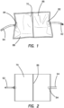
- the film pouch 86 can be formed of a sheet of polymeric film that is folded upon itself and welded to seal edges 88 and create an enclosed volume. With the pouch 86 in a deflated condition, the pouch has a generally rectangular shape with relatively long width and a relatively shorter height. It is contemplated that, the pouch can be formed in other shapes to achieve desired product packaging, aesthetic, or gas flow considerations.
- an inlet port 82 and an outlet port 84 to create a gas flow path through the pouch.
- the inlet port 82 and outlet port 84 are positioned on opposite sides of the pouch 86 to provide a relatively direct flow path along a longitudinal axis of the width of the pouch 86. It is contemplated that other positions of the inlet port 84 and outlet port 86 can be used to vary the gas flow characteristics of the pressure conditioning apparatus.
- the inlet port 82 and outlet port 84 can be positioned adjacent one another along one edge or can be positioned on opposite edges with respect to the height of the pouch 86 such that the pressure conditioning apparatus can have attributes of a side branch attenuator.
- the inlet port 82 and outlet port 84 can each comprise a bag port having a barbed fitting, such as are commercially available from Value Plastics, Inc.
- the pressure conditioning apparatus can further comprise a segment of inlet tubing 92 coupled to the barbed fitting of the inlet port 82 and a segment of outlet tubing 94 coupled to the barbed fitting of the outlet port 84.
- the outlet port 84 could instead be coupled directly to insufflation tubing, or the outlet port 84 and outlet tubing 94 can be formed as a single component.
- the inlet tubing 92 can have a fitting end configured to be coupled to an insufflator or to insufflation tubing from an insufflator.
- the outlet tubing 94 can have a fitting end configured to be coupled to insufflation tubing fluidly coupled to a surgical access port.
- a pressure conditioning apparatus can include only a single length of tubing, or can be provided solely with ports.
- a pressure conditioning apparatus can include an inlet port 82 at an upstream end and an outlet tubing 94 at a downstream end.
- a desired length of inlet tubing can be associated with an insufflator.
- a pressure conditioning apparatus can include an inlet port 82 at an upstream end and an outlet port 84 at a downstream end such that inlet and outlet tubing can be associated with an insufflator and a surgical access port.
- one or both of the inlet and outlet ports can include a luer fitting rather than a barbed fitting such that at least one of the inlet port and the outlet port comprises a luer port. At least one of the inlet port and the outlet port can be heat sealed to the pouch.
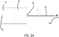
- Figure 3A illustrates a pressure conditioning apparatus 70 having a film pouch 86 with an inlet port 82' having a luer fitting, and an outlet port 84' coupled to a length of outlet tubing 94' that is coupled to an insufflation trocar 940.
- the outlet tubing 94' is a segment of corrugated tubing, which can be desirable in insufflation systems to reduce kinking of the tubing and the potential for related fluid flow disruptions.
- the pouch 86 can be sized and configured to provide pressure conditioning aspects of a separate pressure storage component and accumulator of pressure conditioning devices disclosed herein.
- the pouch can be formed of a polymeric material having predetermined thickness and elasticity properties to provide the desired pressure storage.
- the pouch 86 can be formed of a polyurethane film that can expand and contract responsive to insufflation pressure. It is contemplated that other film materials and/or thicknesses can be used in a pressure conditioning apparatus to achieve the desired pressure storage.
- the pouch 86 can be sized to stabilize the volume of an open-ended body conduit at a surgical site location supplied with pulsed insufflation. As further described with respect to Figures 2 , 3 , and 6-16 , a pouch 86 can be sized to provide a desired pressure conditioning profile for a TAMIS procedure. Desirably, the pouch 86 can have a volume of at least approximately 6.5 liters, between approximately 6.5 and approximately 8 liters, orof approximately 7.4 liters. Where the pouch has a pouch volume that is undesirably small for the surgical site, there can be insufficient pressure storage and accumulated volume to condition pulse cycles of an insufflation pump.
- the pouch is undesirably large for the surgical site, there can be an insufflation lag time as pulse cycles of the insufflator can be influenced by pressure fluctuations of the relatively large pouch volume rather than the surgical site.
- the pouch can be configured with a different pouch volume than the range discussed above for use in patients having particularly small or particularly large colorectal volume.
- the pouch can have a different pouch volume if it is desired to use the pressure conditioning apparatus 70 to condition insufflation pressure pulses at a different surgical site.
- the pressure conditioning apparatus 70 comprises an elastomeric film pouch 86 or bag that can have an inlet port 82 and an outlet port 84 that create a gas flow path through the pouch.
- the pressure conditioning apparatus can further comprise an inlet fluid conduit such as a length of inlet gas tubing 92 and an outlet fluid conduit such as a length of outlet gas tubing 94.
- the inlet gas tubing 92 can include a fitting or coupling to be fluidly coupled to an insufflation pump.
- the inlet gas tubing 92 and outlet gas tubing 94 can be sized relative to one another to provide a desired pressure conditioning profile, where the inlet tubing 92 has a first inner diameter and the outlet tubing 94 can have a second inner diameter larger than the first inner diameter.
- a pressure conditioning apparatus 70 as described herein can be included in a surgical site access system 900 such as a surgical access port 902 having a port surface 904 such as an artificial body wall defined by a gel surface of a surgical access port sold under the trademarks GELPORT and GELPOINT.
- the pressure conditioning apparatus 70 as described herein can be included in a surgical site access system configured for application in a natural orifice entry site surgical procedure such as a TAMIS procedure such as a surgical access port sold as a GELPOINT path system.
- the surgical site access system 900 can comprise a pressure conditioning apparatus 70, a surgical access port 902 having a port surface 904, and a plurality of trocars 930, 940 configured to be advanced through the port surface 904 and to sealingly engage surgical instruments inserted therethrough.
- the surgical access port 902 can comprise at least one insufflation port 910, 920 with the pressure conditioning apparatus 70 can be fluidly coupled to one of the insufflation ports 910, 920.
- the other of the insufflation ports 910, 920 can then either be left free and remain closed with a stopcock valve or other closure device, be coupled to another source of gas, or be selectively opened to provide smoke evacuation for electrosurgical procedures.
- the surgical site access system 900 can further comprise an insufflation trocar 940.
- the pressure conditioning apparatus 70 can be fluidly coupled to the insufflation trocar 940 and the trocar 940 advanced through the artificial body 904 wall to provide insufflation gas flow to the surgical site.
- the insufflation trocar 940 can comprise an instrument access channel 942 and an insufflation port 944.
- the insufflation port 944 of the insufflation trocar 940 can have a relatively large diameter relative to the insufflation ports 910, 920 of the surgical access port 902.
- the insufflation port 944 of the insufflation trocar 940 can comprise a barbed fitting to receive the outlet gas tubing 94 of the pressure conditioning apparatus 70. Accordingly, the insufflation trocar 940 can desirably accommodate insufflation gas flow rates of a fluid coupling such as outlet tubing 94 of a pressure conditioning apparatus 70 having a relatively large inner diameter, such as shown in Figure 2 .
- the pressure conditioning apparatus 70 can be sized and configured to provide a desirable pressure conditioning profile for a surgical site at an open body conduit. For example, it can be desirable for the pressure conditioning apparatus to provide an insufflation gas flow having a relatively small lag time, and a relatively small pressure deviation.
- the lag time represents a time delay between activation of an insufflation pump fluidly coupled to the surgical site access system and reaching a desired insufflation pressure at the surgical site.
- the pressure deviation represents a pressure difference between a high pressure peak and a low pressure peak if insufflation pressure at the surgical site is plotted over time.
- the pressure conditioning apparatus be relatively compact such that it does not require a significant amount of operating room space.
- the insufflation gas pressure conditioning apparatus 70 of Figure 1 is illustrated coupled to a test fixture including a distended simulated body conduit 180.
- the pressure conditioning apparatus 70 is illustrated with the pouch 86 in an inflated condition and a gas flow path (arrows showing flow direction) indicated from the inlet tube segment 92, through the pouch 86, through the outlet tube segment 94 and to the simulated body conduit 180.
- a simulated body conduit 180 can be used to assess the conditioned pressure profile performance of various pressure conditioning apparatus 70 film pouch materials, thicknesses, volumes, and geometries as further discussed with reference to Figures 6-16 .
- the pressure conditioning apparatuses 810 described herein is fluidly coupled to an insufflation pump 800 and fluidly coupled to an open-ended body conduit such as a patient's rectum 820 to define a surgical system configured to maintain a desired insufflation pressure profile.
- Figures 19A-19F label the pressure conditioning apparatuses 810 as 'BAG', the surgical system schematically illustrated incorporates the pouch-based pressure conditioning apparatus described with respect to Figures 1-4 , or another pressure conditioning apparatuses configured to maintain a desired insufflation pressure profile.
- the illustrated embodiment of surgical system comprises a pressure conditioning apparatus 810 fluidly coupled to an insufflation pump 800 by a first fluid coupling 830 and fluidly coupled to a body conduit by a second fluid coupling 840.
- the first fluid coupling 830 and the second fluid coupling 840 can each comprise a segment of gas flow tubing such as are illustrated in Figure 4 .
- the second fluid coupling 840 can be coupled to the body conduit at an insufflation port of a surgical access port such as a cannula or directly through an artificial body wall defined by a gel surface of a surgical access port sold under the trademarks GELPORT and GELPOINT.
- the serial fluid coupling of the pressure conditioning apparatus 810 to the body conduit provided by the first fluid coupling 830 and second fluid coupling 840 of the surgical system result in mitigated pulsing or billowing of the body conduit despite pulsatile operation of the insufflation pump 800.
- the illustrated surgical system also generates a relatively lower pressure at the body conduit as compared with an insufflation pump directly coupled to a body conduit. This relatively low pressure results from the insufflation pump 800 sensing back pressure of the pressure conditioning apparatus 810 at the first fluid coupling 830.
- insufflation pumps 800 are configured to provide a pulsed insufflation profile responsive to pressure variations at a directly-coupled surgical site.
- the system volume added by the pressure conditioning apparatus 810 serially fluidly coupled to the body conduit and the insufflation pump 800 cause the insufflation pump 800 to generate a pulsatile pressure flow response to pressure variations at the first fluid coupling 830 of the system, which may differ from pressure at the body conduit.
- an insufflation system comprises a pressure conditioning apparatus 810 fluidly coupled to an insufflation pump 800 by a first fluid coupling 830 and fluidly coupled to a body conduit by a second fluid coupling 842.
- the second fluid coupling 842 has a thicker cross sectional profile defined by a relatively large inner diameter compared to standard insufflation tubing, which typically has a 6 mm (0.25 inch) inner diameter. This relatively large inner diameter of the second fluid coupling 842 increases the flow rate of insufflation gas from the pressure conditioning apparatus 810 to the body conduit, maintaining a relatively higher pressure in the body conduit than that of the embodiment of Figure 5A .
- an insufflation system in accordance with the present invention comprises a pressure conditioning apparatus 810 fluidly coupled to an insufflation pump 800 by a first fluid coupling 830 and fluidly coupled to a body conduit by a second fluid coupling 840.
- the first fluid coupling 830 comprises a flow splitter such as a y-junction or y-valve to provide a dual lumen insufflation gas delivery pathway having a third fluid coupling 834 providing a parallel fluid flow path from the insufflation pump 800 to the body conduit.
- This dual lumen insufflation gas delivery pathway increases the flow rate of insufflation gas from the insufflation pump 800 to the body conduit, maintaining a relatively higher pressure in the body conduit than that of the embodiment of Figure 5A .
- an insufflation system in accordance with the present invention comprises a pressure conditioning apparatus 810 fluidly coupled to an insufflation pump 800 by a first fluid coupling 830 and fluidly coupled to a body conduit by a second fluid coupling 840.
- the first fluid coupling 830 comprises a one-way valve 836 coupled to a parallel return lumen 838 that is fluidly coupled to the body conduit.
- This one-way valve 836 and return lumen 838 configuration provides backpressure feedback to the insufflation pump 800 while an insufflation gas delivery pathway is provided from the insufflation pump 800 through the pressure conditioning apparatus 810 to the body conduit, thus maintaining a relatively higher pressure in the body conduit than that of the embodiment of Figure 5A .
- an insufflation system in accordance with the present invention comprises a pressure conditioning apparatus 810 fluidly coupled to an insufflation pump 800 by a first fluid coupling 830 and fluidly coupled to a body conduit by a second fluid coupling 840.
- the surgical system further comprises a suction device 860 fluidly coupled to the body conduit by a first return conduit 862 and to the pressure conditioning apparatus 810 by a second return conduit 864, defining an insufflation gas return pathway.
- the gas return pathway can further comprise an in-line filter to prevent hazardous materials from re-entering the body conduit.
- This suction device 860 and return pathway can compensate for insufflation gas loss thus maintaining a desired pressure in the body conduit.
- the surgical system further comprises a suction device 860 fluidly coupled to the body conduit by a first return conduit 866 and a reintroducing conduit 868, defining an insufflation gas return pathway that directly returns insufflation gas to the body conduit.
- the gas return pathway can further comprise an in-line filter to prevent hazardous materials from re-entering the body conduit.
- This suction device 860 and return pathway can compensate for insufflation gas loss thus maintaining a desired pressure in the body conduit.
- Figure 6 illustrates an exemplary observed pressure (in mmHg) at the simulated surgical site over time (in seconds).
- the baseline pressure plot 950 fluctuated between approximately 6mmHg and approximately 25 mmHg, representing a pressure deviation of 19mmHg. This fluctuation results in undesirable billowing of internal walls of the simulated body conduit.
- a pressure plot 960 for a pressure conditioning apparatus including a reservoir having a volume of 3 L is plotted in comparison to the baseline pressure plot 950. As illustrated, the addition of the 3L bag reduced the high to low pressure peak (deviation) to approximately 5mmHg.
- a pressure plot 962 for a pressure conditioning apparatus including a reservoir having a volume of 5.5 L is plotted in comparison to the baseline pressure plot 950. As illustrated, the addition of the 5.5L reservoir reduced the pressure deviation to approximately 3mmHg.
- a pressure plot 964 for a pressure conditioning apparatus including a reservoir having a volume of 6.7 L is plotted in comparison to the baseline pressure plot 950.
- the addition of the 6.7L reservoir reduced the pressure deviation to approximately 2.5mmHg.
- a pressure plot 966 for a pressure conditioning apparatus including a reservoir having a volume of 9 L is plotted in comparison to the baseline pressure plot 950.
- the addition of the 9L reservoir reduced the pressure deviation down to approximately 2mmHg.
- the increased reservoir volume desirably reduced the pressure deviation of the conditioned insufflation gas flow
- the increased reservoir volume also tended to increase the lag time for the surgical site to achieve a desired insufflation pressure.
- the observed lag times ranged from approximately 12 seconds ( Figure 7 ) to approximately 30 seconds ( Figure 10 ).
- the reservoir be sized to provide a relatively low pressure deviation and a relatively low lag time.
- the reservoir be sized for ease of positioning and use in a surgical work environment. Accordingly, in some embodiments, the reservoir can have an internal volume between 5.5 and 8 liters.
- the reservoir can have an internal volume of at least approximately 6.5 liters. In certain embodiments, the reservoir can have an internal volume of approximately 7.4 liters. Desirably, this range of volumes can provide a pressure deviation of under 3 mmHg, a lag time of under 30 seconds, and allow the bag to be positioned relatively easily in a surgical work environment.
- a pressure conditioning profile of a surgical site access system having a pressure conditioning apparatus with a reservoir having an internal volume of 6.5 liters was further verified on a human cadaver.
- a stopcock on the surgical access port was opened to create a 7L/min leak
- the insufflator was set to a flow rate of 9L/min
- insufflation pressure was set at 15mmHg.
- the rectal pressure fluctuated between 2mmHg to 9mmHg (pressure deviation of 7mmHg).
- the control pressure plot 970 representing observed pressure at the simulated surgical site plotted over time, is illustrated in Figure 11 .
- the addition of the pressure conditioning apparatus having a reservoir with a volume of 6.5 liters reduced the pressure deviation to approximately 1mmHg.
- Figure 12 illustrates a pressure plot 972 for the surgical site access system with the pressure conditioning apparatus.
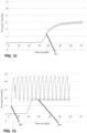
- FIG. 13-16 various embodiments of pressure conditioning apparatus having a reservoir with a volume of 6.5 liters were evaluated such that an inner diameter of an outlet tubing or fluid coupling can be sized and configured to provide a desirable pressure conditioning profile.
- the experimental setup included a simulated, silicone rectum, a GELPOINT Path surgical access system, a pressure conditioning apparatus having a reservoir such as is schematically illustrated in Figure 2 , and a pulsatile insufflator.
- the reservoir of the pressure conditioning apparatus used was 6.5 L in volume.
- the outlet tubing of the pressure conditioning apparatus was coupled to an insufflation trocar positioned through the surgical access system.
- a pressure sensor was inserted into the simulated rectum to measure the internal pressure of the system.
- a GELPOINT Path stopcock was opened approximately half-way to create a leak rate of 10L/min, simulating insufflation gas losses and absorption from an open body conduit.
- the leak rate was kept consistent for all of the embodiments of the pressure conditioning apparatus.
- the insufflator was set at 15mmHg, high flow. The insufflator turned on after 5 seconds. Outlet tubing of varying inner diameter sizes were tested, ranging from 2.5 mm to 13 mm (0.1 inches to 0.5 inches).
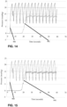
- Figures 13-16 illustrate simulated surgical site pressure conditioning profiles for embodiments of pressure conditioning apparatus having different outlet tubing inner diameters.
- a pressure plot 990 of a pressure conditioning apparatus having an outlet tubing with an inner diameter of 2.5 mm (0.1 inches) is illustrated in comparison to a baseline pressure plot 980 of the setup with no pressure conditioning apparatus.
- This embodiment of pressure conditioning apparatus maintained a pressure at the simulated surgical site of approximately 9 mmHg.
- the resulting pressure conditioning profile has a relatively high pressure drop, defined by the difference between the set pressure of the insufflator and the observed pressure at the surgical site.
- the pressure conditioning profile has relatively small pressure deviation.
- a pressure plot 992 of a pressure conditioning apparatus having an outlet tubing with an inner diameter of 4 mm (0.15 inches) is illustrated in comparison to a baseline pressure plot 980.
- the pressure conditioning profile maintains a pressure of approximately 13 mmHg, with a pressure deviation of approximately 1 mmHg.
- a pressure plot 994 of a pressure conditioning apparatus having an outlet tubing with an inner diameter of 6.3 mm (0.25 inches) is illustrated in comparison to a baseline pressure plot 980.
- the pressure conditioning profile maintains a pressure of approximately 14 mmHg, with a pressure deviation of approximately 1.5 mmHg.
- a pressure plot 996 of a pressure conditioning apparatus having an outlet tubing with an inner diameter of 13 mm (0.5 inches) is illustrated in comparison to a baseline pressure plot 980.
- the pressure conditioning profile maintains a pressure of approximately 14.5 mmHg, with a pressure deviation of approximately 2 mmHg.
- comparing the pressure conditioning profiles of various embodiments of pressure conditioning apparatus indicates that the smaller the outlet tubing inner diameter, the greater overall colorectal system pressure drop, but the smaller the pressure differential.
- a relatively larger tubing inner diameter tends to yield a pressure conditioning profile with minimized colorectal system pressure drop and a relatively larger pressure differential.
- the outlet tubing can have an inner diameter that is desirably in the range of from approximately 6 mm (0.25 inches) to approximately 13 mm (0.5 inches). In certain embodiments, the outlet tubing can have an inner diameter of approximately 13 mm (0.5 inches).
- a 13 mm (0.5 inches) inner diameter tubing has a relatively small pressure drop and a clinically acceptable pressure differential. In a cadaver lab, a pressure differential of 2mmHg was not visually noticeable. Therefore, the pressure differential caused a 13 mm (0.5 inches) inner diameter tubing is acceptable.
- Insufflation tubing such as the inlet tubing coupling the pressure conditioning apparatus to an insufflation pump can typically have an inner diameter of approximately 6 mm (0.25 inches). Thus, it is desirable that the outlet tubing has a larger inner diameter than the inlet tubing. In the embodiment of pressure conditioning apparatus having an outlet tube with a 13 mm (0.5 inches) inner diameter, the inner diameter of the outlet tubing can be at least twice the inner diameter of the inlet tubing.
Description
- The present disclosure relates to a surgical insufflation system with pressure conditioning apparatus to act to maintain a substantially constant pressure at a surgical site despite pulsing or discontinuous insufflation supply and leakage and absorption at the surgical site.
- During Trans Anal Minimally Invasive Surgery (TAMIS) an insufflation machine is used to inflate the rectum with an insufflation gas such as carbon dioxide (CO2). The inflation allows room for a surgeon to perform a surgical procedure using laparoscopic instruments and techniques. Many insufflation machines provide CO2 in pulses, alternating pressurization pulses with pressure measurements. The colorectal system, however, is not a sealed volume and CO2 continuously leaks from the inflated surgical area causing the pressure to drop. Additionally, CO2 is readily absorbed by the walls of the colorectal system thereby exacerbating the loss of pressure caused by the leakage. CO2 can leak from the system through a variety of leak paths, ranging from the length of the colorectal system, absorption by the intestine/colorectal walls, and through the surgical instruments and tools used to gain access. At some points of the procedure, a smoke evacuation port is constantly open in order to encourage the flow of CO2, forcing out smoke generated by electrocautery. The multitude of leak paths leads to a loss of pressure and pulsed insufflation flow manifests itself as billowing of the rectal walls. The billowing follows the pressure cycle from the insufflation machine: when the machine is providing CO2 pressure the rectal walls expand and when the insufflation machine is not supplying pressure (measuring the pressure) the rectal walls contract. The movement of the rectal walls can make laparoscopic surgery more difficult during a TAMIS, or other transanal procedure, which can require manipulation of and treatment of growths on the rectal walls.
- Patent Applications bearing publication numbers
EP2329774A1 ,WO2014/077806A1 andUS2013/245381 A1 disclose known examples of insufflation systems. - In various embodiments, the apparatuses described herein can significantly reduce tissue billowing of an open-ended body conduit such as a rectal cavity that is insufflated by a pulsing insufflation pump. The apparatuses can condition a pulsed or discontinuous insufflation gas flow to provide a substantially continuous insufflation gas flow that can have a flow rate that varies responsive to pressure losses at an inlet from a zero pressure differential state between pulses of an insufflation pump and backpressure reduction at an outlet due to leakage and absorption by tissue at a surgical site in an open-ended body conduit.
- In accordance with the present invention there is provided an insufflation system as recited in Claim 1.
-
-
Figure 1 is a side view of an of a gas flow pressure conditioning apparatus for use in an insufflation system in accordance with the present invention; -
Figure 2 is a schematic view of the pressure conditioning apparatus ofFigure 1 for use in a surgical site access system; -
Figure 3 is a schematic view of a surgical site access system including the pressure conditioning apparatus ofFigure 1 ; -
Figure 3A is a schematic view of another pressure conditioning apparatus for a surgical site access system; -
Figure 4 is a perspective view of the pressure conditioning apparatus ofFigure 1 in an expanded configuration on a test fixture with a simulated body conduit; -
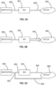
Figure 5A is a schematic view of one embodiment of a surgical insufflation system including a gas flow pressure conditioning apparatus; -
Figure 5B is a schematic view of an embodiment of an insufflation system including a gas flow pressure conditioning apparatus; -
Figure 5C is a schematic view of another embodiment of an insufflation system in accordance with the present invention including a gas flow pressure conditioning apparatus; -
Figure 5D is a schematic view of another embodiment of an insufflation system in accordance with the present invention including a gas flow pressure conditioning apparatus; -
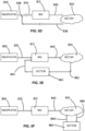
Figure 5E is a schematic view of another embodiment of an insufflation system in accordance with the present invention including a gas flow pressure conditioning apparatus; -
Figure 5F is a schematic view of another embodiment of an insufflation system in accordance with the present invention including a gas flow pressure conditioning apparatus; -
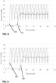
Figure 6 is a graph of surgical site pressure over time for a simulated surgical access site insufflated with a pulsatile insufflation pump; -
Figure 7 is a graph of surgical site pressure over time for a simulated surgical access site insufflated with a pulsatile insufflation pump and an insufflation system in accordance with the present invention; -
Figure 8 is a graph of surgical site pressure over time for a simulated surgical access site insufflated with a pulsatile insufflation pump and another insufflation system in accordance with the present invention; -
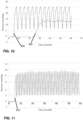
Figure 9 is a graph of surgical site pressure over time for a simulated surgical access site insufflated with a pulsatile insufflation pump and another insufflation system in accordance with the present invention; -
Figure 10 is a graph of surgical site pressure over time for a simulated surgical access site insufflated with a pulsatile insufflation pump and another insufflation system in accordance with the present invention; -
Figure 11 is a graph of surgical site pressure over time for a simulated surgical access site in a cadaver laboratory setting insufflated with a pulsatile insufflation pump; -
Figure 12 is a graph of surgical site pressure over time for a simulated surgical access site of Figure 25 insufflated with a pulsatile insufflation pump and an insufflation system in accordance with the present invention; -
Figure 13 is a graph of surgical site pressure over time for a simulated surgical access site insufflated with a pulsatile insufflation pump and an insufflation system in accordance with the present invention; -
Figure 14 is a graph of surgical site pressure over time for a simulated surgical access site insufflated with a pulsatile insufflation pump and another insufflation system in accordance with the present invention; -
Figure 15 is a graph of surgical site pressure over time for a simulated surgical access site insufflated with a pulsatile insufflation pump and another insufflation system in accordance with the present invention; -
Figure 16 is a graph of surgical site pressure over time for a simulated surgical access site insufflated with a pulsatile insufflation pump and another insufflation system in accordance with the present invention. - A gas insufflation pressure conditioning apparatus can be fluidly coupled to a pulsing insufflation machine to alleviate billowing of a body conduit and reduce or eliminate the movement of the rectum walls when using the pulsing insufflation machine in a TAMIS procedure. The pressure conditioning apparatus can be configured to maintain a substantially constant pressure and flow in the body conduit despite leakage and absorption from the body conduit at the surgical site and a pulsing insufflation gas flow profile. Additionally, billowing can be further alleviated through provision of a body conduit sealing or closure device to create a closed volume within the rectal cavity to minimize the pressure lost while eliminating the movement of the rectum walls.
- With reference to
Figures 1-4 an insufflation gaspressure conditioning apparatus 70 is illustrated. Thepressure conditioning apparatus 70 comprises a gas flow path extending from a segment ofinlet gas tubing 92 through an elastomeric film pouch to a segment ofoutlet gas tubing 94. The elastomeric film pouch provides pressure conditioning functions of pressure storage, insufflation gas volume accumulation, and flow restriction to maintain a substantially consistent insufflation gas flow at a surgical site despite a discontinuous, pulsatile flow from an insufflator. - With reference to
Figure 1 , thefilm pouch 86 can be formed of a sheet of polymeric film that is folded upon itself and welded toseal edges 88 and create an enclosed volume. With thepouch 86 in a deflated condition, the pouch has a generally rectangular shape with relatively long width and a relatively shorter height. It is contemplated that, the pouch can be formed in other shapes to achieve desired product packaging, aesthetic, or gas flow considerations. - With continued reference to
Figure 1 , aninlet port 82 and anoutlet port 84 to create a gas flow path through the pouch. In the illustrated arrangement, theinlet port 82 andoutlet port 84 are positioned on opposite sides of thepouch 86 to provide a relatively direct flow path along a longitudinal axis of the width of thepouch 86. It is contemplated that other positions of theinlet port 84 andoutlet port 86 can be used to vary the gas flow characteristics of the pressure conditioning apparatus. For example, theinlet port 82 andoutlet port 84 can be positioned adjacent one another along one edge or can be positioned on opposite edges with respect to the height of thepouch 86 such that the pressure conditioning apparatus can have attributes of a side branch attenuator. - The
inlet port 82 andoutlet port 84 can each comprise a bag port having a barbed fitting, such as are commercially available from Value Plastics, Inc. The pressure conditioning apparatus can further comprise a segment ofinlet tubing 92 coupled to the barbed fitting of theinlet port 82 and a segment ofoutlet tubing 94 coupled to the barbed fitting of theoutlet port 84. Theoutlet port 84 could instead be coupled directly to insufflation tubing, or theoutlet port 84 andoutlet tubing 94 can be formed as a single component. Theinlet tubing 92 can have a fitting end configured to be coupled to an insufflator or to insufflation tubing from an insufflator. Theoutlet tubing 94 can have a fitting end configured to be coupled to insufflation tubing fluidly coupled to a surgical access port. - While the illustrated arrangement includes both an
inlet tubing 92 and anoutlet tubing 94, it can be desirable that the pressure conditioning apparatus include only a single length of tubing, or can be provided solely with ports. For example, a pressure conditioning apparatus can include aninlet port 82 at an upstream end and anoutlet tubing 94 at a downstream end. Thus a desired length of inlet tubing can be associated with an insufflator. Alternatively , a pressure conditioning apparatus can include aninlet port 82 at an upstream end and anoutlet port 84 at a downstream end such that inlet and outlet tubing can be associated with an insufflator and a surgical access port. Moreover, one or both of the inlet and outlet ports can include a luer fitting rather than a barbed fitting such that at least one of the inlet port and the outlet port comprises a luer port. At least one of the inlet port and the outlet port can be heat sealed to the pouch.Figure 3A illustrates apressure conditioning apparatus 70 having afilm pouch 86 with an inlet port 82' having a luer fitting, and an outlet port 84' coupled to a length of outlet tubing 94' that is coupled to aninsufflation trocar 940. Here the outlet tubing 94' is a segment of corrugated tubing, which can be desirable in insufflation systems to reduce kinking of the tubing and the potential for related fluid flow disruptions. - The
pouch 86 can be sized and configured to provide pressure conditioning aspects of a separate pressure storage component and accumulator of pressure conditioning devices disclosed herein. For example, the pouch can be formed of a polymeric material having predetermined thickness and elasticity properties to provide the desired pressure storage. Thepouch 86 can be formed of a polyurethane film that can expand and contract responsive to insufflation pressure. It is contemplated that other film materials and/or thicknesses can be used in a pressure conditioning apparatus to achieve the desired pressure storage. - The
pouch 86 can be sized to stabilize the volume of an open-ended body conduit at a surgical site location supplied with pulsed insufflation. As further described with respect toFigures 2 ,3 , and6-16 , apouch 86 can be sized to provide a desired pressure conditioning profile for a TAMIS procedure. Desirably, thepouch 86 can have a volume of at least approximately 6.5 liters, between approximately 6.5 and approximately 8 liters, orof approximately 7.4 liters. Where the pouch has a pouch volume that is undesirably small for the surgical site, there can be insufficient pressure storage and accumulated volume to condition pulse cycles of an insufflation pump. Where the pouch is undesirably large for the surgical site, there can be an insufflation lag time as pulse cycles of the insufflator can be influenced by pressure fluctuations of the relatively large pouch volume rather than the surgical site. It is contemplated that the pouch can be configured with a different pouch volume than the range discussed above for use in patients having particularly small or particularly large colorectal volume. Likewise, it is contemplated that the pouch can have a different pouch volume if it is desired to use thepressure conditioning apparatus 70 to condition insufflation pressure pulses at a different surgical site. - With reference to
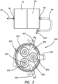
Figure 2 , the pressure conditioning apparatus ofFigure 1 is schematically illustrated. Thepressure conditioning apparatus 70 comprises anelastomeric film pouch 86 or bag that can have aninlet port 82 and anoutlet port 84 that create a gas flow path through the pouch. The pressure conditioning apparatus can further comprise an inlet fluid conduit such as a length ofinlet gas tubing 92 and an outlet fluid conduit such as a length ofoutlet gas tubing 94. Theinlet gas tubing 92 can include a fitting or coupling to be fluidly coupled to an insufflation pump. - With continued reference to
Figure 2 theinlet gas tubing 92 andoutlet gas tubing 94 can be sized relative to one another to provide a desired pressure conditioning profile, where theinlet tubing 92 has a first inner diameter and theoutlet tubing 94 can have a second inner diameter larger than the first inner diameter. - With reference to
Figures 2-3 , apressure conditioning apparatus 70 as described herein can be included in a surgicalsite access system 900 such as asurgical access port 902 having aport surface 904 such as an artificial body wall defined by a gel surface of a surgical access port sold under the trademarks GELPORT and GELPOINT. Thepressure conditioning apparatus 70 as described herein can be included in a surgical site access system configured for application in a natural orifice entry site surgical procedure such as a TAMIS procedure such as a surgical access port sold as a GELPOINT path system. In general, the surgicalsite access system 900 can comprise apressure conditioning apparatus 70, asurgical access port 902 having aport surface 904, and a plurality oftrocars port surface 904 and to sealingly engage surgical instruments inserted therethrough. - With continued reference to
Figure 3 , thesurgical access port 902 can comprise at least oneinsufflation port pressure conditioning apparatus 70 can be fluidly coupled to one of theinsufflation ports insufflation ports - With continued reference to
Figure 3 , the surgicalsite access system 900 can further comprise aninsufflation trocar 940. Thepressure conditioning apparatus 70 can be fluidly coupled to theinsufflation trocar 940 and thetrocar 940 advanced through theartificial body 904 wall to provide insufflation gas flow to the surgical site. Theinsufflation trocar 940 can comprise aninstrument access channel 942 and aninsufflation port 944. Theinsufflation port 944 of theinsufflation trocar 940 can have a relatively large diameter relative to theinsufflation ports surgical access port 902. Theinsufflation port 944 of theinsufflation trocar 940 can comprise a barbed fitting to receive theoutlet gas tubing 94 of thepressure conditioning apparatus 70. Accordingly, theinsufflation trocar 940 can desirably accommodate insufflation gas flow rates of a fluid coupling such asoutlet tubing 94 of apressure conditioning apparatus 70 having a relatively large inner diameter, such as shown inFigure 2 . - The
pressure conditioning apparatus 70 can be sized and configured to provide a desirable pressure conditioning profile for a surgical site at an open body conduit. For example, it can be desirable for the pressure conditioning apparatus to provide an insufflation gas flow having a relatively small lag time, and a relatively small pressure deviation. The lag time represents a time delay between activation of an insufflation pump fluidly coupled to the surgical site access system and reaching a desired insufflation pressure at the surgical site. The pressure deviation represents a pressure difference between a high pressure peak and a low pressure peak if insufflation pressure at the surgical site is plotted over time. Moreover, it can be desirable that the pressure conditioning apparatus be relatively compact such that it does not require a significant amount of operating room space. - With reference to
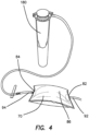
Figure 4 , the insufflation gaspressure conditioning apparatus 70 ofFigure 1 is illustrated coupled to a test fixture including a distendedsimulated body conduit 180. Thepressure conditioning apparatus 70 is illustrated with thepouch 86 in an inflated condition and a gas flow path (arrows showing flow direction) indicated from theinlet tube segment 92, through thepouch 86, through theoutlet tube segment 94 and to thesimulated body conduit 180. Desirably, asimulated body conduit 180, can be used to assess the conditioned pressure profile performance of variouspressure conditioning apparatus 70 film pouch materials, thicknesses, volumes, and geometries as further discussed with reference toFigures 6-16 . - With reference to
Figures 5A-5F in various embodiments, thepressure conditioning apparatuses 810 described herein is fluidly coupled to aninsufflation pump 800 and fluidly coupled to an open-ended body conduit such as a patient'srectum 820 to define a surgical system configured to maintain a desired insufflation pressure profile. While Figures 19A-19F label thepressure conditioning apparatuses 810 as 'BAG', the surgical system schematically illustrated incorporates the pouch-based pressure conditioning apparatus described with respect toFigures 1-4 , or another pressure conditioning apparatuses configured to maintain a desired insufflation pressure profile. - With reference to
Figure 5A , the illustrated embodiment of surgical system comprises apressure conditioning apparatus 810 fluidly coupled to aninsufflation pump 800 by a firstfluid coupling 830 and fluidly coupled to a body conduit by a secondfluid coupling 840. Arrowheads schematically illustrate a direction of fluid flow within the surgical system. In some embodiments, the firstfluid coupling 830 and the secondfluid coupling 840 can each comprise a segment of gas flow tubing such as are illustrated inFigure 4 . In some embodiments, the secondfluid coupling 840 can be coupled to the body conduit at an insufflation port of a surgical access port such as a cannula or directly through an artificial body wall defined by a gel surface of a surgical access port sold under the trademarks GELPORT and GELPOINT. - With continued reference to
Figure 5A , in operation, the serial fluid coupling of thepressure conditioning apparatus 810 to the body conduit provided by the firstfluid coupling 830 and secondfluid coupling 840 of the surgical system result in mitigated pulsing or billowing of the body conduit despite pulsatile operation of theinsufflation pump 800. The illustrated surgical system also generates a relatively lower pressure at the body conduit as compared with an insufflation pump directly coupled to a body conduit. This relatively low pressure results from theinsufflation pump 800 sensing back pressure of thepressure conditioning apparatus 810 at the firstfluid coupling 830. Typically, insufflation pumps 800 are configured to provide a pulsed insufflation profile responsive to pressure variations at a directly-coupled surgical site. However, the system volume added by thepressure conditioning apparatus 810 serially fluidly coupled to the body conduit and theinsufflation pump 800 cause theinsufflation pump 800 to generate a pulsatile pressure flow response to pressure variations at the firstfluid coupling 830 of the system, which may differ from pressure at the body conduit. - With reference to
Figures 5B-5F , in various surgical systems, it can be desirable to reduce the pressure loss at a body conduit that tends to result from a serially-coupledpressure conditioning apparatus 810. With reference toFigure 5B , an insufflation system comprises apressure conditioning apparatus 810 fluidly coupled to aninsufflation pump 800 by a firstfluid coupling 830 and fluidly coupled to a body conduit by a secondfluid coupling 842. The secondfluid coupling 842 has a thicker cross sectional profile defined by a relatively large inner diameter compared to standard insufflation tubing, which typically has a 6 mm (0.25 inch) inner diameter. This relatively large inner diameter of the secondfluid coupling 842 increases the flow rate of insufflation gas from thepressure conditioning apparatus 810 to the body conduit, maintaining a relatively higher pressure in the body conduit than that of the embodiment ofFigure 5A . - With reference to
Figure 5C , an insufflation system in accordance with the present invention comprises apressure conditioning apparatus 810 fluidly coupled to aninsufflation pump 800 by a firstfluid coupling 830 and fluidly coupled to a body conduit by a secondfluid coupling 840. The firstfluid coupling 830 comprises a flow splitter such as a y-junction or y-valve to provide a dual lumen insufflation gas delivery pathway having a thirdfluid coupling 834 providing a parallel fluid flow path from theinsufflation pump 800 to the body conduit. This dual lumen insufflation gas delivery pathway increases the flow rate of insufflation gas from theinsufflation pump 800 to the body conduit, maintaining a relatively higher pressure in the body conduit than that of the embodiment ofFigure 5A . - With reference to
Figure 5D , an insufflation system in accordance with the present invention comprises apressure conditioning apparatus 810 fluidly coupled to aninsufflation pump 800 by a firstfluid coupling 830 and fluidly coupled to a body conduit by a secondfluid coupling 840. The firstfluid coupling 830 comprises a one-way valve 836 coupled to aparallel return lumen 838 that is fluidly coupled to the body conduit. This one-way valve 836 and return lumen 838 configuration provides backpressure feedback to theinsufflation pump 800 while an insufflation gas delivery pathway is provided from theinsufflation pump 800 through thepressure conditioning apparatus 810 to the body conduit, thus maintaining a relatively higher pressure in the body conduit than that of the embodiment ofFigure 5A . - With reference to
Figure 5E , an insufflation system in accordance with the present invention comprises apressure conditioning apparatus 810 fluidly coupled to aninsufflation pump 800 by a firstfluid coupling 830 and fluidly coupled to a body conduit by a secondfluid coupling 840. The surgical system further comprises asuction device 860 fluidly coupled to the body conduit by afirst return conduit 862 and to thepressure conditioning apparatus 810 by asecond return conduit 864, defining an insufflation gas return pathway. Thus, insufflation gas drawn out of the body conduit is reintroduced to the body conduit by way of thepressure conditioning apparatus 810. The gas return pathway can further comprise an in-line filter to prevent hazardous materials from re-entering the body conduit. Thissuction device 860 and return pathway can compensate for insufflation gas loss thus maintaining a desired pressure in the body conduit. - With reference to
Figure 5F , an insufflation system in accordance with the present invention comprises apressure conditioning apparatus 810 fluidly coupled to aninsufflation pump 800 by a firstfluid coupling 830 and fluidly coupled to a body conduit by a secondfluid coupling 840. The surgical system further comprises asuction device 860 fluidly coupled to the body conduit by afirst return conduit 866 and a reintroducingconduit 868, defining an insufflation gas return pathway that directly returns insufflation gas to the body conduit. Thus, insufflation gas drawn out of the body conduit is reintroduced to the body conduit by way of the reintroducingconduit 868. The gas return pathway can further comprise an in-line filter to prevent hazardous materials from re-entering the body conduit. Thissuction device 860 and return pathway can compensate for insufflation gas loss thus maintaining a desired pressure in the body conduit. - With reference to
Figures 6-16 , by assessing pressure conditioning performance over a series of simulated leakage tests including several embodiments of pressure conditioning apparatus, desirable configurations of the pressure conditioning apparatus can be identified. With reference toFigure 6 , baseline results in a test fixture of a simulated leak test including a silicone simulated rectum, a GELPOINT Path surgical access system and a standard pulsatile insufflator are illustrated. A pressure sensor was inserted into the simulated rectum to measure the internal pressure of the system. In a control setup, a GELPOINT Path stopcock was opened approximately half-way to create a leak rate of 10L/min. The leak rate was kept consistent throughout subsequent tests of different embodiments of pressure conditioning apparatus ofFigures 7-10 . The insufflator was set at 15mmHg, high flow. The insufflator turned on after 5 seconds. -
Figure 6 illustrates an exemplary observed pressure (in mmHg) at the simulated surgical site over time (in seconds). As illustrated, in the baseline or control configuration with no pressure conditioning apparatus, after an initial lag time of over 5 seconds, thebaseline pressure plot 950 fluctuated between approximately 6mmHg and approximately 25 mmHg, representing a pressure deviation of 19mmHg. This fluctuation results in undesirable billowing of internal walls of the simulated body conduit. - With reference to
Figures 7-10 , various embodiments of pressure conditioning apparatus were incorporated into a simulated surgical site access system for comparison with the baseline or control pressure plot. With reference toFigure 7 , apressure plot 960 for a pressure conditioning apparatus including a reservoir having a volume of 3 L is plotted in comparison to thebaseline pressure plot 950. As illustrated, the addition of the 3L bag reduced the high to low pressure peak (deviation) to approximately 5mmHg. With reference toFigure 8 , apressure plot 962 for a pressure conditioning apparatus including a reservoir having a volume of 5.5 L is plotted in comparison to thebaseline pressure plot 950. As illustrated, the addition of the 5.5L reservoir reduced the pressure deviation to approximately 3mmHg. With reference toFigure 9 , apressure plot 964 for a pressure conditioning apparatus including a reservoir having a volume of 6.7 L is plotted in comparison to thebaseline pressure plot 950. The addition of the 6.7L reservoir reduced the pressure deviation to approximately 2.5mmHg. With reference toFigure 10 , apressure plot 966 for a pressure conditioning apparatus including a reservoir having a volume of 9 L is plotted in comparison to thebaseline pressure plot 950. The addition of the 9L reservoir reduced the pressure deviation down to approximately 2mmHg. - With continued reference to
Figures 7-10 , while an increased reservoir volume desirably reduced the pressure deviation of the conditioned insufflation gas flow, the increased reservoir volume also tended to increase the lag time for the surgical site to achieve a desired insufflation pressure. For example, in the embodiments used in the simulated leakage tests, the observed lag times ranged from approximately 12 seconds (Figure 7 ) to approximately 30 seconds (Figure 10 ). Accordingly, in certain embodiments, it can be desirable that the reservoir be sized to provide a relatively low pressure deviation and a relatively low lag time. Moreover, it can be desirable that the reservoir be sized for ease of positioning and use in a surgical work environment. Accordingly, in some embodiments, the reservoir can have an internal volume between 5.5 and 8 liters. More desirably, the reservoir can have an internal volume of at least approximately 6.5 liters. In certain embodiments, the reservoir can have an internal volume of approximately 7.4 liters. Desirably, this range of volumes can provide a pressure deviation of under 3 mmHg, a lag time of under 30 seconds, and allow the bag to be positioned relatively easily in a surgical work environment. - With reference to
Figures 11-12 , a pressure conditioning profile of a surgical site access system having a pressure conditioning apparatus with a reservoir having an internal volume of 6.5 liters was further verified on a human cadaver. In an experimental surgical access system setup, a stopcock on the surgical access port was opened to create a 7L/min leak, the insufflator was set to a flow rate of 9L/min, and insufflation pressure was set at 15mmHg. In a control or baseline test, the rectal pressure fluctuated between 2mmHg to 9mmHg (pressure deviation of 7mmHg). Thecontrol pressure plot 970, representing observed pressure at the simulated surgical site plotted over time, is illustrated inFigure 11 . The addition of the pressure conditioning apparatus having a reservoir with a volume of 6.5 liters reduced the pressure deviation to approximately 1mmHg.Figure 12 illustrates apressure plot 972 for the surgical site access system with the pressure conditioning apparatus. - With reference to
Figures 13-16 , various embodiments of pressure conditioning apparatus having a reservoir with a volume of 6.5 liters were evaluated such that an inner diameter of an outlet tubing or fluid coupling can be sized and configured to provide a desirable pressure conditioning profile. The experimental setup included a simulated, silicone rectum, a GELPOINT Path surgical access system, a pressure conditioning apparatus having a reservoir such as is schematically illustrated inFigure 2 , and a pulsatile insufflator. The reservoir of the pressure conditioning apparatus used was 6.5 L in volume. The outlet tubing of the pressure conditioning apparatus was coupled to an insufflation trocar positioned through the surgical access system. A pressure sensor was inserted into the simulated rectum to measure the internal pressure of the system. In the control setup, a GELPOINT Path stopcock was opened approximately half-way to create a leak rate of 10L/min, simulating insufflation gas losses and absorption from an open body conduit. The leak rate was kept consistent for all of the embodiments of the pressure conditioning apparatus. The insufflator was set at 15mmHg, high flow. The insufflator turned on after 5 seconds. Outlet tubing of varying inner diameter sizes were tested, ranging from 2.5 mm to 13 mm (0.1 inches to 0.5 inches).Figures 13-16 illustrate simulated surgical site pressure conditioning profiles for embodiments of pressure conditioning apparatus having different outlet tubing inner diameters. - With reference to
Figure 13 , apressure plot 990 of a pressure conditioning apparatus having an outlet tubing with an inner diameter of 2.5 mm (0.1 inches) is illustrated in comparison to abaseline pressure plot 980 of the setup with no pressure conditioning apparatus. This embodiment of pressure conditioning apparatus maintained a pressure at the simulated surgical site of approximately 9 mmHg. Thus, the resulting pressure conditioning profile has a relatively high pressure drop, defined by the difference between the set pressure of the insufflator and the observed pressure at the surgical site. However, the pressure conditioning profile has relatively small pressure deviation. - With reference to
Figure 14 , apressure plot 992 of a pressure conditioning apparatus having an outlet tubing with an inner diameter of 4 mm (0.15 inches) is illustrated in comparison to abaseline pressure plot 980. As illustrated, the pressure conditioning profile maintains a pressure of approximately 13 mmHg, with a pressure deviation of approximately 1 mmHg. With reference toFigure 15 , apressure plot 994 of a pressure conditioning apparatus having an outlet tubing with an inner diameter of 6.3 mm (0.25 inches) is illustrated in comparison to abaseline pressure plot 980. As illustrated, the pressure conditioning profile maintains a pressure of approximately 14 mmHg, with a pressure deviation of approximately 1.5 mmHg. With reference toFigure 16 , apressure plot 996 of a pressure conditioning apparatus having an outlet tubing with an inner diameter of 13 mm (0.5 inches) is illustrated in comparison to abaseline pressure plot 980. As illustrated, the pressure conditioning profile maintains a pressure of approximately 14.5 mmHg, with a pressure deviation of approximately 2 mmHg. - With continued reference to
Figures 13-16 , comparing the pressure conditioning profiles of various embodiments of pressure conditioning apparatus indicates that the smaller the outlet tubing inner diameter, the greater overall colorectal system pressure drop, but the smaller the pressure differential. Correspondingly, a relatively larger tubing inner diameter tends to yield a pressure conditioning profile with minimized colorectal system pressure drop and a relatively larger pressure differential. - It can be desirable that the insufflation pressure maintained by the surgical site access system has a relatively low pressure drop and a pressure deviation that is clinically acceptable. Accordingly, in some embodiments, the outlet tubing can have an inner diameter that is desirably in the range of from approximately 6 mm (0.25 inches) to approximately 13 mm (0.5 inches). In certain embodiments, the outlet tubing can have an inner diameter of approximately 13 mm (0.5 inches). Advantageously, a 13 mm (0.5 inches) inner diameter tubing has a relatively small pressure drop and a clinically acceptable pressure differential. In a cadaver lab, a pressure differential of 2mmHg was not visually noticeable. Therefore, the pressure differential caused a 13 mm (0.5 inches) inner diameter tubing is acceptable. Insufflation tubing such as the inlet tubing coupling the pressure conditioning apparatus to an insufflation pump can typically have an inner diameter of approximately 6 mm (0.25 inches). Thus, it is desirable that the outlet tubing has a larger inner diameter than the inlet tubing. In the embodiment of pressure conditioning apparatus having an outlet tube with a 13 mm (0.5 inches) inner diameter, the inner diameter of the outlet tubing can be at least twice the inner diameter of the inlet tubing.
Claims (6)
- An insufflation system for use with a pulsatile insufflation pump (800) operable at a set pressure, the insufflation system comprising:a pressure conditioning apparatus (70, 810) configured to receive a discontinuous insufflation gas flow from the pulsatile insufflation pump at the set pressure and deliver a substantially consistent insufflation gas flow to a surgical site at a site pressure, the pressure conditioning apparatus (70) comprising an elastomeric film pouch (86) comprising an inlet port (82, 82') and an outlet port (84) defining a gas flow path therebetween, wherein the elastomeric film is sized and configured to expand and contract responsive to a pressure of the gas flow;a first fluid coupling (830) fluidly coupled to the pressure conditioning apparatus and configured to couple to the pulsatile insufflation pump (800); anda second fluid coupling (840, 842) fluidly coupled to the pressure conditioning apparatus (70) and configured to couple to the surgical site; andwherein a difference between the site pressure and the set pressure of the insufflation pump defines a pressure loss and characterised in that the system is configured to reduce the pressure loss by an arrangement wherein either:(a) the insufflation system further comprises a flow splitter in the first fluid coupling (830); and a third fluid coupling (834) configured to provide a parallel fluid pathway between the flow splitter and the surgical site;(b) the insufflation system further comprises a return lumen (838) having an upstream end configured to fluidly couple to the surgical site and a downstream end opposite the upstream end; and a one-way valve (836) fluidly coupled to the downstream end and the first fluid coupling (830);(c) the insufflation system further comprises a first return conduit (862) configured to fluidly couple to the surgical site; a second return conduit (864) fluidly coupled to the pressure conditioning apparatus (810); and a suction device (860) fluidly coupled to the first return conduit (862) and the second return conduit (864) to define an insufflation gas return pathway; or(d) the insufflation system further comprises a first return conduit (866) configured to fluidly couple to the surgical site; a reintroducing conduit (868) configured to fluidly couple to the surgical site; and a suction device (860) fluidly coupled to the first return conduit (866) and the reintroducing conduit (868) to define an insufflation gas return pathway.
- The insufflation system of claim 1, wherein the elastomeric film pouch (86) has a pressure storage volume of at least 6.5 liters.
- The apparatus of any of the preceding claims, wherein the elastomeric film pouch (86) comprises a sheet of polymeric film folded upon itself and having sealed edges defining an enclosed volume.
- The apparatus of claim 3, wherein the elastomeric film (86) pouch has a generally rectangular shape.
- The apparatus of any of the preceding claims, wherein the inlet port (82, 82') and the outlet port (84) are positioned on opposite sides of the elastomeric film pouch.
- The apparatus of any of the preceding claims, wherein the elastomeric film pouch (86) comprises a polyurethane film material.
Priority Applications (2)
| Application Number | Priority Date | Filing Date | Title |
|---|---|---|---|
| EP24161170.6A EP4353167A2 (en) | 2015-09-30 | 2016-09-30 | Insufflation stabilization system |
| EP22214324.0A EP4169556A1 (en) | 2015-09-30 | 2016-09-30 | Insufflation stabilization system |
Applications Claiming Priority (5)
| Application Number | Priority Date | Filing Date | Title |
|---|---|---|---|
| US201562235128P | 2015-09-30 | 2015-09-30 | |
| US201662327941P | 2016-04-26 | 2016-04-26 | |
| EP16781637.0A EP3355974B1 (en) | 2015-09-30 | 2016-09-30 | Insufflation stabilization system |
| PCT/US2016/054955 WO2017059335A1 (en) | 2015-09-30 | 2016-09-30 | Insufflation stabilization system |
| EP20151520.2A EP3656428B1 (en) | 2015-09-30 | 2016-09-30 | Insufflation stabilization system |
Related Parent Applications (3)
| Application Number | Title | Priority Date | Filing Date |
|---|---|---|---|
| EP16781637.0A Division EP3355974B1 (en) | 2015-09-30 | 2016-09-30 | Insufflation stabilization system |
| EP20151520.2A Division EP3656428B1 (en) | 2015-09-30 | 2016-09-30 | Insufflation stabilization system |
| EP20151520.2A Division-Into EP3656428B1 (en) | 2015-09-30 | 2016-09-30 | Insufflation stabilization system |
Related Child Applications (3)
| Application Number | Title | Priority Date | Filing Date |
|---|---|---|---|
| EP24161170.6A Division EP4353167A2 (en) | 2015-09-30 | 2016-09-30 | Insufflation stabilization system |
| EP22214324.0A Division EP4169556A1 (en) | 2015-09-30 | 2016-09-30 | Insufflation stabilization system |
| EP22214324.0A Division-Into EP4169556A1 (en) | 2015-09-30 | 2016-09-30 | Insufflation stabilization system |
Publications (2)
| Publication Number | Publication Date |
|---|---|
| EP3895749A1 EP3895749A1 (en) | 2021-10-20 |
| EP3895749B1 true EP3895749B1 (en) | 2023-02-22 |
Family
ID=57133448
Family Applications (5)
| Application Number | Title | Priority Date | Filing Date |
|---|---|---|---|
| EP16781637.0A Active EP3355974B1 (en) | 2015-09-30 | 2016-09-30 | Insufflation stabilization system |
| EP20151520.2A Active EP3656428B1 (en) | 2015-09-30 | 2016-09-30 | Insufflation stabilization system |
| EP22214324.0A Pending EP4169556A1 (en) | 2015-09-30 | 2016-09-30 | Insufflation stabilization system |
| EP24161170.6A Pending EP4353167A2 (en) | 2015-09-30 | 2016-09-30 | Insufflation stabilization system |
| EP21169881.6A Active EP3895749B1 (en) | 2015-09-30 | 2016-09-30 | Insufflation stabilization system |
Family Applications Before (4)
| Application Number | Title | Priority Date | Filing Date |
|---|---|---|---|
| EP16781637.0A Active EP3355974B1 (en) | 2015-09-30 | 2016-09-30 | Insufflation stabilization system |
| EP20151520.2A Active EP3656428B1 (en) | 2015-09-30 | 2016-09-30 | Insufflation stabilization system |
| EP22214324.0A Pending EP4169556A1 (en) | 2015-09-30 | 2016-09-30 | Insufflation stabilization system |
| EP24161170.6A Pending EP4353167A2 (en) | 2015-09-30 | 2016-09-30 | Insufflation stabilization system |
Country Status (8)
| Country | Link |
|---|---|
| US (4) | US9956358B2 (en) |
| EP (5) | EP3355974B1 (en) |
| JP (4) | JP6800220B2 (en) |
| KR (1) | KR102656617B1 (en) |
| AU (3) | AU2016331945B2 (en) |
| CA (1) | CA3000663A1 (en) |
| ES (3) | ES2883823T3 (en) |
| WO (1) | WO2017059335A1 (en) |
Families Citing this family (6)
| Publication number | Priority date | Publication date | Assignee | Title |
|---|---|---|---|---|
| WO2017059335A1 (en) * | 2015-09-30 | 2017-04-06 | Applied Medical Resources Corporation | Insufflation stabilization system |
| CN208910475U (en) * | 2018-01-31 | 2019-05-31 | 前海三雷斯医疗科技(深圳)有限公司 | A kind of surgical pathway system |
| EP3840804A4 (en) * | 2018-08-23 | 2022-05-04 | Fisher & Paykel Healthcare Limited | Supplementary continuous gas supply source for delivery to surgical cavities |
| KR102138120B1 (en) * | 2018-09-21 | 2020-07-27 | 국립암센터 | Apparatus for stabilizing supply of gas |
| KR102320826B1 (en) * | 2018-12-10 | 2021-11-02 | 주식회사 인코아 | Apparatus For Intra-Abdominal Pressure Maintenance |
| CN111412869B (en) * | 2020-04-17 | 2021-04-20 | 大连理工大学 | Detection device and method for crack size of pressure-bearing shell wall based on gas leakage rate measurement |
Family Cites Families (37)
| Publication number | Priority date | Publication date | Assignee | Title |
|---|---|---|---|---|
| US3858572A (en) * | 1972-10-27 | 1975-01-07 | Kendall & Co | Insufflation device |
| FR2326734A1 (en) | 1975-10-04 | 1977-04-29 | Wolf Gmbh Richard | GAS INSUFFLATION APPARATUS APPLICABLE IN PARTICULAR TO THE FILLING OF A BODY CAVITY |
| DE3413631A1 (en) | 1984-04-11 | 1985-10-24 | Semm, Kurt, Prof. Dr.Med., 2300 Kiel | MONOFILE DEVICE FOR INSUFFLING GAS |
| DE3718717A1 (en) | 1987-06-04 | 1988-12-22 | Wolf Gmbh Richard | DEVICE FOR INSUFFLING GAS INTO A BODY CAVE |
| DE3739003A1 (en) | 1987-11-17 | 1989-05-24 | Wolf Gmbh Richard | INSUFFLATION DEVICE FOR ENDOSCOPIC INTERVENTIONS |
| DE69325037T2 (en) | 1992-07-07 | 2000-01-05 | 544456 B C Ltd | DEVICE FOR IMPROVED INSUFFLATION |
| US5322070A (en) * | 1992-08-21 | 1994-06-21 | E-Z-Em, Inc. | Barium enema insufflation system |
| US5439441A (en) | 1993-10-12 | 1995-08-08 | Snowden-Pencer, Inc. | Surgical insufflation system with improved determination of body cavity pressure |
| US5800381A (en) | 1994-02-25 | 1998-09-01 | Ognier; Jean-François | Medical gas insufflator with automatic gas flow control |
| US5569205A (en) * | 1994-07-14 | 1996-10-29 | Hart; Charles C. | Multiport trocar |
| DE19510710C2 (en) * | 1995-03-15 | 2001-11-22 | Dmv Medizintechnik Gmbh | Insufflation gas conditioning device |
| US6458093B1 (en) | 1999-02-05 | 2002-10-01 | Storz Endoskop Gmbh | Apparatus for insufflating gas into a corporeal cavity of a human or animal body |
| US6402714B1 (en) | 1999-11-12 | 2002-06-11 | Karl Storz Gmbh & Co., Kg | Apparatus and method for controlling high flow insufflation |
| JP2002204829A (en) * | 2000-09-08 | 2002-07-23 | Pall Corp | Cannula assembly |
| DE10233861A1 (en) | 2002-07-19 | 2004-02-12 | Storz Endoskop Produktions Gmbh | Device, insufflation device, measuring device and method for insufflating a body cavity with an insufflation gas |
| AU2003279823A1 (en) * | 2002-10-28 | 2004-05-25 | Northgate Technologies Inc. | Dual-capacity insufflator tube |
| US7854724B2 (en) | 2003-04-08 | 2010-12-21 | Surgiquest, Inc. | Trocar assembly with pneumatic sealing |
| US7285112B2 (en) * | 2003-04-08 | 2007-10-23 | Surgiquest, Incorporated | Gas flow trocar arrangement |
| US7806850B2 (en) | 2005-10-24 | 2010-10-05 | Bracco Diagnostics Inc. | Insufflating system, method, and computer program product for controlling the supply of a distending media to an endoscopic device |
| US20070208300A1 (en) * | 2006-03-01 | 2007-09-06 | Applied Medical Resources Corporation | Gas insufflation and suction/irrigation tubing |
| CA2842217C (en) * | 2006-09-08 | 2016-09-06 | Surgiquest, Incorporated | Trocar assembly with pneumatic sealing |
| ATE498364T1 (en) * | 2006-09-08 | 2011-03-15 | Surgiquest Inc | TROCALER ARRANGEMENT WITH PNEUMATIC CLOSURE |
| CN101611094B (en) * | 2007-02-12 | 2012-03-21 | 帝斯曼知识产权资产管理有限公司 | Polymer composition and plastic tube made thereof |
| EP2341849B1 (en) * | 2008-10-10 | 2019-12-18 | SurgiQuest, Incorporated | System for improved gas recirculation in surgical trocars with pneumatic sealing |
| US9381312B1 (en) * | 2009-03-18 | 2016-07-05 | Douglas E. Ott | Insufflation apparatus |
| US8366667B2 (en) | 2010-02-11 | 2013-02-05 | Baxter International Inc. | Flow pulsatility dampening devices |
| US9421032B2 (en) * | 2010-06-16 | 2016-08-23 | Covidien Lp | Seal port with blood collector |
| US9289115B2 (en) * | 2010-10-01 | 2016-03-22 | Applied Medical Resources Corporation | Natural orifice surgery system |
| EP2621348B1 (en) | 2010-10-01 | 2019-06-12 | Applied Medical Resources Corporation | Natural orifice surgery system |
| US9522017B2 (en) | 2010-12-03 | 2016-12-20 | Minimally Invasive Devices, Inc. | Devices, systems, and methods for performing endoscopic surgical procedures |
| JP5384548B2 (en) * | 2011-03-28 | 2014-01-08 | 富士フイルム株式会社 | Endoscopic air supply system |
| JP6066428B2 (en) * | 2011-05-02 | 2017-01-25 | アプライド メディカル リソーシーズ コーポレイション | Low profile surgical universal access port |
| WO2013142150A1 (en) | 2012-03-22 | 2013-09-26 | Genii, Inc. | Gas flow control apparatus and related methods |
| JP5566544B2 (en) * | 2012-06-27 | 2014-08-06 | オリンパスメディカルシステムズ株式会社 | Air supply system, operation system, and air supply method |
| WO2014077806A1 (en) * | 2012-11-14 | 2014-05-22 | Rudolf Albert | Disposable insufflation device |
| US10406301B2 (en) * | 2012-12-24 | 2019-09-10 | Lexion Medical, Llc | Fail-safe insufflators |
| WO2017059335A1 (en) * | 2015-09-30 | 2017-04-06 | Applied Medical Resources Corporation | Insufflation stabilization system |
-
2016
- 2016-09-30 WO PCT/US2016/054955 patent/WO2017059335A1/en active Application Filing
- 2016-09-30 JP JP2018516424A patent/JP6800220B2/en active Active
- 2016-09-30 US US15/282,781 patent/US9956358B2/en active Active
- 2016-09-30 EP EP16781637.0A patent/EP3355974B1/en active Active
- 2016-09-30 CA CA3000663A patent/CA3000663A1/en active Pending
- 2016-09-30 ES ES20151520T patent/ES2883823T3/en active Active
- 2016-09-30 EP EP20151520.2A patent/EP3656428B1/en active Active
- 2016-09-30 ES ES16781637T patent/ES2784727T3/en active Active
- 2016-09-30 ES ES21169881T patent/ES2941887T3/en active Active
- 2016-09-30 EP EP22214324.0A patent/EP4169556A1/en active Pending
- 2016-09-30 EP EP24161170.6A patent/EP4353167A2/en active Pending
- 2016-09-30 AU AU2016331945A patent/AU2016331945B2/en active Active
- 2016-09-30 EP EP21169881.6A patent/EP3895749B1/en active Active
- 2016-09-30 KR KR1020187012339A patent/KR102656617B1/en active IP Right Grant
-
2018
- 2018-03-21 US US15/927,477 patent/US10493219B2/en active Active
-
2019
- 2019-11-01 US US16/671,587 patent/US11648359B2/en active Active
-
2020
- 2020-11-24 JP JP2020194533A patent/JP7027511B2/en active Active
-
2021
- 2021-05-14 AU AU2021203095A patent/AU2021203095B2/en active Active
-
2022
- 2022-02-16 JP JP2022022252A patent/JP7386274B2/en active Active
-
2023
- 2023-04-05 US US18/296,200 patent/US20230321369A1/en active Pending
- 2023-07-04 AU AU2023204299A patent/AU2023204299A1/en active Pending
- 2023-11-13 JP JP2023192857A patent/JP2024019177A/en active Pending
Also Published As
Similar Documents
| Publication | Publication Date | Title |
|---|---|---|
| EP3895749B1 (en) | Insufflation stabilization system | |
| JP6788740B2 (en) | Multimode surgical gas delivery system with continuous pressure monitoring of continuous gas flow into the body cavity | |
| JP6661650B2 (en) | Filter cartridge with internal gas seal used for a multi-mode surgical gas delivery system with a smoke evacuation mode | |
| JP7322092B2 (en) | A multimodal surgical gas delivery system configured to maintain a stable body cavity pressure when suction is used within the body cavity | |
| JP4695890B2 (en) | Pneumoperitoneum needle | |
| US20210361886A1 (en) | Medical Device with Improved Desufflation | |
| JP5411597B2 (en) | Pressurized surgical valve |
Legal Events
| Date | Code | Title | Description |
|---|---|---|---|
| PUAI | Public reference made under article 153(3) epc to a published international application that has entered the european phase |
Free format text: ORIGINAL CODE: 0009012 |
|
| STAA | Information on the status of an ep patent application or granted ep patent |
Free format text: STATUS: REQUEST FOR EXAMINATION WAS MADE |
|
| 17P | Request for examination filed |
Effective date: 20210422 |
|
| AC | Divisional application: reference to earlier application |
Ref document number: 3355974 Country of ref document: EP Kind code of ref document: P Ref document number: 3656428 Country of ref document: EP Kind code of ref document: P |
|
| AK | Designated contracting states |
Kind code of ref document: A1 Designated state(s): AL AT BE BG CH CY CZ DE DK EE ES FI FR GB GR HR HU IE IS IT LI LT LU LV MC MK MT NL NO PL PT RO RS SE SI SK SM TR |
|
| B565 | Issuance of search results under rule 164(2) epc |
Effective date: 20210830 |
|
| STAA | Information on the status of an ep patent application or granted ep patent |
Free format text: STATUS: EXAMINATION IS IN PROGRESS |
|
| 17Q | First examination report despatched |
Effective date: 20220706 |
|
| GRAP | Despatch of communication of intention to grant a patent |
Free format text: ORIGINAL CODE: EPIDOSNIGR1 |
|
| STAA | Information on the status of an ep patent application or granted ep patent |
Free format text: STATUS: GRANT OF PATENT IS INTENDED |
|
| RIC1 | Information provided on ipc code assigned before grant |
Ipc: A61B 17/34 20060101ALN20220831BHEP Ipc: A61M 13/00 20060101AFI20220831BHEP |
|
| INTG | Intention to grant announced |
Effective date: 20220916 |
|
| RIC1 | Information provided on ipc code assigned before grant |
Ipc: A61B 17/34 20060101ALN20220906BHEP Ipc: A61M 13/00 20060101AFI20220906BHEP |
|
| GRAS | Grant fee paid |
Free format text: ORIGINAL CODE: EPIDOSNIGR3 |
|
| GRAA | (expected) grant |
Free format text: ORIGINAL CODE: 0009210 |
|
| STAA | Information on the status of an ep patent application or granted ep patent |
Free format text: STATUS: THE PATENT HAS BEEN GRANTED |
|
| AC | Divisional application: reference to earlier application |
Ref document number: 3355974 Country of ref document: EP Kind code of ref document: P Ref document number: 3656428 Country of ref document: EP Kind code of ref document: P |
|
| AK | Designated contracting states |
Kind code of ref document: B1 Designated state(s): AL AT BE BG CH CY CZ DE DK EE ES FI FR GB GR HR HU IE IS IT LI LT LU LV MC MK MT NL NO PL PT RO RS SE SI SK SM TR |
|
| REG | Reference to a national code |
Ref country code: GB Ref legal event code: FG4D |
|
| REG | Reference to a national code |
Ref country code: CH Ref legal event code: EP |
|
| REG | Reference to a national code |
Ref country code: NL Ref legal event code: FP |
|
| REG | Reference to a national code |
Ref country code: DE Ref legal event code: R096 Ref document number: 602016078023 Country of ref document: DE |
|
| REG | Reference to a national code |
Ref country code: AT Ref legal event code: REF Ref document number: 1549114 Country of ref document: AT Kind code of ref document: T Effective date: 20230315 Ref country code: IE Ref legal event code: FG4D |
|
| REG | Reference to a national code |
Ref country code: ES Ref legal event code: FG2A Ref document number: 2941887 Country of ref document: ES Kind code of ref document: T3 Effective date: 20230526 |
|
| REG | Reference to a national code |
Ref country code: LT Ref legal event code: MG9D |
|
| P01 | Opt-out of the competence of the unified patent court (upc) registered |
Effective date: 20230524 |
|
| REG | Reference to a national code |
Ref country code: AT Ref legal event code: MK05 Ref document number: 1549114 Country of ref document: AT Kind code of ref document: T Effective date: 20230222 |
|
| PG25 | Lapsed in a contracting state [announced via postgrant information from national office to epo] |
Ref country code: RS Free format text: LAPSE BECAUSE OF FAILURE TO SUBMIT A TRANSLATION OF THE DESCRIPTION OR TO PAY THE FEE WITHIN THE PRESCRIBED TIME-LIMIT Effective date: 20230222 Ref country code: PT Free format text: LAPSE BECAUSE OF FAILURE TO SUBMIT A TRANSLATION OF THE DESCRIPTION OR TO PAY THE FEE WITHIN THE PRESCRIBED TIME-LIMIT Effective date: 20230622 Ref country code: NO Free format text: LAPSE BECAUSE OF FAILURE TO SUBMIT A TRANSLATION OF THE DESCRIPTION OR TO PAY THE FEE WITHIN THE PRESCRIBED TIME-LIMIT Effective date: 20230522 Ref country code: LV Free format text: LAPSE BECAUSE OF FAILURE TO SUBMIT A TRANSLATION OF THE DESCRIPTION OR TO PAY THE FEE WITHIN THE PRESCRIBED TIME-LIMIT Effective date: 20230222 Ref country code: LT Free format text: LAPSE BECAUSE OF FAILURE TO SUBMIT A TRANSLATION OF THE DESCRIPTION OR TO PAY THE FEE WITHIN THE PRESCRIBED TIME-LIMIT Effective date: 20230222 Ref country code: HR Free format text: LAPSE BECAUSE OF FAILURE TO SUBMIT A TRANSLATION OF THE DESCRIPTION OR TO PAY THE FEE WITHIN THE PRESCRIBED TIME-LIMIT Effective date: 20230222 Ref country code: AT Free format text: LAPSE BECAUSE OF FAILURE TO SUBMIT A TRANSLATION OF THE DESCRIPTION OR TO PAY THE FEE WITHIN THE PRESCRIBED TIME-LIMIT Effective date: 20230222 |
|
| PG25 | Lapsed in a contracting state [announced via postgrant information from national office to epo] |
Ref country code: SE Free format text: LAPSE BECAUSE OF FAILURE TO SUBMIT A TRANSLATION OF THE DESCRIPTION OR TO PAY THE FEE WITHIN THE PRESCRIBED TIME-LIMIT Effective date: 20230222 Ref country code: PL Free format text: LAPSE BECAUSE OF FAILURE TO SUBMIT A TRANSLATION OF THE DESCRIPTION OR TO PAY THE FEE WITHIN THE PRESCRIBED TIME-LIMIT Effective date: 20230222 Ref country code: IS Free format text: LAPSE BECAUSE OF FAILURE TO SUBMIT A TRANSLATION OF THE DESCRIPTION OR TO PAY THE FEE WITHIN THE PRESCRIBED TIME-LIMIT Effective date: 20230622 Ref country code: GR Free format text: LAPSE BECAUSE OF FAILURE TO SUBMIT A TRANSLATION OF THE DESCRIPTION OR TO PAY THE FEE WITHIN THE PRESCRIBED TIME-LIMIT Effective date: 20230523 Ref country code: FI Free format text: LAPSE BECAUSE OF FAILURE TO SUBMIT A TRANSLATION OF THE DESCRIPTION OR TO PAY THE FEE WITHIN THE PRESCRIBED TIME-LIMIT Effective date: 20230222 |
|
| PG25 | Lapsed in a contracting state [announced via postgrant information from national office to epo] |
Ref country code: SM Free format text: LAPSE BECAUSE OF FAILURE TO SUBMIT A TRANSLATION OF THE DESCRIPTION OR TO PAY THE FEE WITHIN THE PRESCRIBED TIME-LIMIT Effective date: 20230222 Ref country code: RO Free format text: LAPSE BECAUSE OF FAILURE TO SUBMIT A TRANSLATION OF THE DESCRIPTION OR TO PAY THE FEE WITHIN THE PRESCRIBED TIME-LIMIT Effective date: 20230222 Ref country code: EE Free format text: LAPSE BECAUSE OF FAILURE TO SUBMIT A TRANSLATION OF THE DESCRIPTION OR TO PAY THE FEE WITHIN THE PRESCRIBED TIME-LIMIT Effective date: 20230222 Ref country code: DK Free format text: LAPSE BECAUSE OF FAILURE TO SUBMIT A TRANSLATION OF THE DESCRIPTION OR TO PAY THE FEE WITHIN THE PRESCRIBED TIME-LIMIT Effective date: 20230222 Ref country code: CZ Free format text: LAPSE BECAUSE OF FAILURE TO SUBMIT A TRANSLATION OF THE DESCRIPTION OR TO PAY THE FEE WITHIN THE PRESCRIBED TIME-LIMIT Effective date: 20230222 |
|
| PGFP | Annual fee paid to national office [announced via postgrant information from national office to epo] |
Ref country code: NL Payment date: 20230926 Year of fee payment: 8 Ref country code: IE Payment date: 20230927 Year of fee payment: 8 Ref country code: GB Payment date: 20230927 Year of fee payment: 8 Ref country code: IT Payment date: 20230921 Year of fee payment: 8 |
|
| REG | Reference to a national code |
Ref country code: DE Ref legal event code: R097 Ref document number: 602016078023 Country of ref document: DE |
|
| PG25 | Lapsed in a contracting state [announced via postgrant information from national office to epo] |
Ref country code: SK Free format text: LAPSE BECAUSE OF FAILURE TO SUBMIT A TRANSLATION OF THE DESCRIPTION OR TO PAY THE FEE WITHIN THE PRESCRIBED TIME-LIMIT Effective date: 20230222 |
|
| PGFP | Annual fee paid to national office [announced via postgrant information from national office to epo] |
Ref country code: FR Payment date: 20230925 Year of fee payment: 8 Ref country code: DE Payment date: 20230927 Year of fee payment: 8 |
|
| PLBE | No opposition filed within time limit |
Free format text: ORIGINAL CODE: 0009261 |
|
| STAA | Information on the status of an ep patent application or granted ep patent |
Free format text: STATUS: NO OPPOSITION FILED WITHIN TIME LIMIT |
|
| PGFP | Annual fee paid to national office [announced via postgrant information from national office to epo] |
Ref country code: ES Payment date: 20231002 Year of fee payment: 8 |
|
| 26N | No opposition filed |
Effective date: 20231123 |
|
| PG25 | Lapsed in a contracting state [announced via postgrant information from national office to epo] |
Ref country code: SI Free format text: LAPSE BECAUSE OF FAILURE TO SUBMIT A TRANSLATION OF THE DESCRIPTION OR TO PAY THE FEE WITHIN THE PRESCRIBED TIME-LIMIT Effective date: 20230222 |