EP3895616A1 - Method and device for steering infrared light source, especially for eye safety - Google Patents
Method and device for steering infrared light source, especially for eye safety Download PDFInfo
- Publication number
- EP3895616A1 EP3895616A1 EP20465519.5A EP20465519A EP3895616A1 EP 3895616 A1 EP3895616 A1 EP 3895616A1 EP 20465519 A EP20465519 A EP 20465519A EP 3895616 A1 EP3895616 A1 EP 3895616A1
- Authority
- EP
- European Patent Office
- Prior art keywords
- light source
- infrared light
- current
- steering
- pulse
- Prior art date
- Legal status (The legal status is an assumption and is not a legal conclusion. Google has not performed a legal analysis and makes no representation as to the accuracy of the status listed.)
- Pending
Links
Images



Classifications
-
- A—HUMAN NECESSITIES
- A61—MEDICAL OR VETERINARY SCIENCE; HYGIENE
- A61B—DIAGNOSIS; SURGERY; IDENTIFICATION
- A61B5/00—Measuring for diagnostic purposes; Identification of persons
- A61B5/16—Devices for psychotechnics; Testing reaction times ; Devices for evaluating the psychological state
- A61B5/18—Devices for psychotechnics; Testing reaction times ; Devices for evaluating the psychological state for vehicle drivers or machine operators
-
- A—HUMAN NECESSITIES
- A61—MEDICAL OR VETERINARY SCIENCE; HYGIENE
- A61B—DIAGNOSIS; SURGERY; IDENTIFICATION
- A61B5/00—Measuring for diagnostic purposes; Identification of persons
- A61B5/68—Arrangements of detecting, measuring or recording means, e.g. sensors, in relation to patient
- A61B5/6887—Arrangements of detecting, measuring or recording means, e.g. sensors, in relation to patient mounted on external non-worn devices, e.g. non-medical devices
- A61B5/6893—Cars
-
- H—ELECTRICITY
- H05—ELECTRIC TECHNIQUES NOT OTHERWISE PROVIDED FOR
- H05B—ELECTRIC HEATING; ELECTRIC LIGHT SOURCES NOT OTHERWISE PROVIDED FOR; CIRCUIT ARRANGEMENTS FOR ELECTRIC LIGHT SOURCES, IN GENERAL
- H05B45/00—Circuit arrangements for operating light-emitting diodes [LED]
- H05B45/10—Controlling the intensity of the light
-
- H—ELECTRICITY
- H05—ELECTRIC TECHNIQUES NOT OTHERWISE PROVIDED FOR
- H05B—ELECTRIC HEATING; ELECTRIC LIGHT SOURCES NOT OTHERWISE PROVIDED FOR; CIRCUIT ARRANGEMENTS FOR ELECTRIC LIGHT SOURCES, IN GENERAL
- H05B45/00—Circuit arrangements for operating light-emitting diodes [LED]
- H05B45/30—Driver circuits
- H05B45/32—Pulse-control circuits
- H05B45/325—Pulse-width modulation [PWM]
-
- H—ELECTRICITY
- H05—ELECTRIC TECHNIQUES NOT OTHERWISE PROVIDED FOR
- H05B—ELECTRIC HEATING; ELECTRIC LIGHT SOURCES NOT OTHERWISE PROVIDED FOR; CIRCUIT ARRANGEMENTS FOR ELECTRIC LIGHT SOURCES, IN GENERAL
- H05B47/00—Circuit arrangements for operating light sources in general, i.e. where the type of light source is not relevant
- H05B47/10—Controlling the light source
- H05B47/105—Controlling the light source in response to determined parameters
-
- H—ELECTRICITY
- H05—ELECTRIC TECHNIQUES NOT OTHERWISE PROVIDED FOR
- H05B—ELECTRIC HEATING; ELECTRIC LIGHT SOURCES NOT OTHERWISE PROVIDED FOR; CIRCUIT ARRANGEMENTS FOR ELECTRIC LIGHT SOURCES, IN GENERAL
- H05B47/00—Circuit arrangements for operating light sources in general, i.e. where the type of light source is not relevant
- H05B47/20—Responsive to malfunctions or to light source life; for protection
- H05B47/26—Circuit arrangements for protecting against earth faults
Definitions
- the present invention relates to an Infrared Light Source Steering Method and Device, especially for eye safety used in Driver Monitoring Systems.
- a Driver Monitoring System also known as Driver Attention Monitor, is a vehicle safety system that uses infrared sensors to monitor driver attentiveness.
- the DMS includes an infrared camera which is capable of eye tracking, with the aid of for example infrared LEDs or infrared VCSELs (vertical-cavity surface-emitting laser) for the illumination of the eyes. If the driver is not paying attention to the road ahead and a dangerous situation is detected, the system will warn the driver or take over car control.
- illumination infrared LEDs, infrared VCSELs or other infrared (IR) sources are activated with current pulses having different amplitude and length.
- IR infrared
- Infrared radiation can cause thermal retina hazard or cornea thermal injury and limits with the given conditions are regulated by IEC 60825-1, IEC 62471 standards for IR-A radiation and European Directive 2006/25/EC.
- Cornea exposure limit is defined as the maximum allowed irradiance EIR_max, for different time scales of exposure inside IR-A spectrum.
- EIR_max 100[W/m ⁇ 2].
- I_LED 1.5[A]
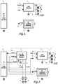
- FIG.1 A typical implementation of a Prior Art DMS is presented in Fig.1 and comprises an infrared camera sensor 3 which controls an LED driver 2 using an activation signal, named STROBE 10.
- IIR I_LED kl * I_LED W / sr were
- camera sensor STROBE pulse width is adapted to ambiental lighting conditions. In case of improper STROBE pulse parameters generated by algorithms or system failure or close eye proximity to IR source, the amount of optical irradiance could exceed eye safety limits.
- the task of the present invention is to provide a method and device for infrared light source irradiance limit for providing safety for the eyes, i.e. that the eyes are not injured by the IR LED pulses in any way.
- Reshaping means limiting the pulse width and /or the pulse amplitude sent out from the infrared light source. So single or several pulses can be suppressed totally or cut in pulse width and/ or pulse amplitude even if requested for a required illumination intensity of a device, in which the invention is used, would request an amount of infrared light critical for the human eye.
- the constant function depends from the maximum allowed infrared energy for the human eye correlated with the distance between the human eye and the infrared light source, it is assured that the amount of infrared light sent to the human eye is in a safe condition.
- the distance between the human eye and the infrared light source is measured it is assured that under every circumstance, that the amount of infrared light sent from the infrared light source to the human eye is in a safe scope.
- the invention is suitable for example for use in a driver monitoring system and/or or a cabin monitoring system, since especially during the use of such systems in night time an illumination which will not distract or hinder a driver of a vehicle is required for the use of one or more cameras used by these systems.
- a device for steering an infrared light source comprising a light sensor, whereby the device executes one or more methods of the invention it is received a device assuring the eye safety of a possible user of such an infrared light source.
- the device comprises a sensor for measuring the distance between the human eye and the infrared light source it is assured that the amount of light sent to the human eye is safe under every condition, even if a user is nearer to the infrared light source than expected by the designers of such a system.
- the device according to the invention comprises a pulse limiter circuit (1) comprising analog and logical circuits and is based on a timing capacitor charge/discharge method a good designable and steerable device can be reached.
- the inventive method can be executed in digital form using software as will be demonstrated more in detail for a possible solution later.
- the infrared light source comprises one or more LEDs a functional and durable light source is constructed.
- the infrared light source comprises one or more VCSELs a low power consuming light source is created.
- a proximity sensor for measuring the distance between human eye and infrared light source is present the security for the eyes can be received in every situation.
- the proximity sensor is a proximity infrared sensor the illumination of the infrared light source can be used.
- a first embodiment of the invention in Fig.2 refers to a method and device for DMS camera eye safety optical irradiance limit by LED driver circuit parameters monitor and limit to avoid driver eye hazard, thus limit average optical irradiance of infrared LEDs or VCSELs as part of DMS implementation for ASIL-A and ASIL-B compliance.
- Pulse limiter circuit 1 can be implemented as a standalone or embedded 6 into the LED driver circuit 2.
- the first embodiment of the invention further comprises a micro-processing unit or ser/deser circuit 5, according to DMS architecture, an infrared camera sensor 3, an LED driver 2, and one or several IR LEDs or VCSELs 4a, 4b.
- a STROBE pulse 10 from the infrared camera sensor 3 activates the LED driver 2 via pulse limiter circuit 1.
- LEDs current 13 amplitude is set via V_ISET voltage 15 and timing parameters are limited for PWM_OUT signal 12.
- Pulse limiter circuit 1 features a logic level input PWM_IN 11, a logic level output PWM_OUT 12, an open drain active low fault reporting output nFAULT 14 and two set pins 21 and 22 for on-time and duty-cycle limit setting using external resistors 24 and 25 or voltage references or a serial port 23, I2C or SPI.
- a second embodiment of the invention in Fig 3 refers to a method and device for DMS camera eye safety optical irradiance limit by LED driver circuit parameters monitor and limit to avoid driver eye hazard, thus limit average optical irradiance of infrared LEDs or VCSELs as part of DMS implementation for ASIL-A and ASIL-B compliance.
- the second embodiment of the invention increases further eye safety level by correlating LEDs current with eye proximity information using a conditioning circuit 8 to modulate the current set reference voltage V_ISET_ref 27 with a proximity sensor 7 output modulation voltage V_PROX 28.
- V_ISET_ref Current set reference voltage V_ISET_ref is as well limited to a limit value V_ISET_ref_lim inside the conditioning circuit by using voltage limiting components like Zenner diodes or shunt regulators.
- the LEDs current, set by V_ISET 15, should follow the same square law as radiant intensity from equation (3):
- V_ISET kv * V_ISET_ref * V_PROX ⁇ 2 V were
- IIR I_LED kl * gdrv * kv * V_ISET_ref * km * d ⁇ 2 W / sr
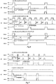
- the way how the average LEDs current is limited by keeping V_ISET below V_ISET_ref_lim and PWM_OUT duty-cycle below Dc_lim is presented in Fig.4 .
- the device input signal PWM_IN 11(STROBE 10) is monitored by checking the on-time t_on_IN and duty-cycle Dc_IN. Limiting conditions of t_on_lim and Dc_lim are applied to PWM_OUT 12 by limit the t_on_OUT and Dc_OUT.
- Pulse parameters are defined as follows:
- the PWM output pulse on time is limited to t_on_lim, based on IR LED thermal management considerations.
- the PWM output pulse duty-cycle is limited to Dc_lim and the IR LED average radiant intensity limited to Dc_lim of pulse peak radiant in intensity. If the PWM frequency is increased but t_on_IN ⁇ t_on_lim AND Dc_IN ⁇ Dc-lim, input pulses are reproduced at the output and no-fault condition is reported.
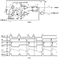
- a first implementation of such pulse limiter uses analog and logical circuits and is based on a timing capacitor charge/discharge method using different charge/discharge current set values between two voltage threshold levels.
- the circuit shown in Fig.8 comprises a controlled constant current source circuit 33 with the charge current Ic 49 set by resistor 21, a controlled constant current sink circuit 34 with the discharge current Id 50 set by resistor 22, a timing capacitor Ct, a window comparator circuit using comparator circuits 39 and 40 using reference voltages Vth 55 and Vtl 56 generated by a voltage reference Vref 48 divided by resistors 36, 36 and 38, an inverted inputs RS flip-flop 41, an AND gate logical circuit 42 which passes through or blocks the PWM_IN 10 pulses to the output PWM_OUT 12 according to nFAULT logic level, a logical inverter circuit 30 controls the constant current circuits according to signal CT 54 logic level.
- the timing capacitor is charged with a charge current Ic. If PWM_IN pulse on-time is higher than the capacitor charge time to the high-level threshold voltage Vth 55 then RS flip-flop 41 is reset and gate 42 will cut remaining part of the pulse at PWM_OUT. In this way, the circuit implements the on-time limit function.
- timing capacitor is discharged with a discharge current Id until capacitor voltage V_Ct 51 decreases below low-level threshold voltage Vtl 56.
- Discharge time is called also blanking time because the gate is locked and no PWM_IN pulse passes through.
- RS flip-flop 41 is set and gate 42 is unlocked. If no valid pulse is present at PWM_IN, timing capacitor is discharged completely, and another monitoring cycle can be started. In this way, the circuit implements the off-time limit function.
- Fig. 9 shows a timing diagram of the implemented device shown in Fig. 8 for different pulse conditions: Pulse A on-time is higher than on-time limit and duty-cycle higher than duty-cycle limit so part of it is cut. Pulse B on-time is equal with on-time limit and duty-cycle lower than duty-cycle limit but arrives during pulse A blanking time thus part of it is cut.
- Pulse C on-time is smaller than on-time limit, but the duty-cycle is higher than the duty-cycle limit and pulse D is cut completely because arrives during pulse C blanking time.
- Pulse D on-time is much higher than on-time limit and the duty-cycle is much higher than duty-cycle limit, thus pulse on-time is limited to on-time limit and duty-cycle is limited to duty-cycle limit.
- Another implementation variant comprises a microcontroller by using a GPIO timing port for PWM_IN and two GPIO ports for PWM_OUT and fault reporting nFAULT output.
- the logic diagram of such an embodiment is shown in Fig. 10 .
- a monitoring cycle is composed by two sequences: on-time monitoring sequence and blanking time sequence.
- the device is initialized by setting the on-time limit, duty-cycle limit.
- PWM output is set to LOW logic level.
- PWM_OUT output When PWM_IN input goes HIGH then PWM_OUT output is set to HIGH logic level and the device starts the on-time monitoring sequence by measuring the PWM_IN pulse on-time. If measured on-time is smaller than the on-time limit, PWM_OUT output is set to LOW logic level and the blanking time is calculated based on duty-cycle limit. If PWM_IN input stays on HIGH logic level more than the on-time limit, PWM_OUT output is set to LOW logic level, nFAULT output is set to LOW logic level (active) and the blanking time is calculated based on on-time and duty-cycle limits.
- nFAULT output is set to HIGH logic level (inactive).
- the device checks the PWM_IN input for another valid HIGH logic level and a new monitoring cycle begins.
- the invention can be used in a wide range of applications. Examples are:
Landscapes
- Health & Medical Sciences (AREA)
- Life Sciences & Earth Sciences (AREA)
- Engineering & Computer Science (AREA)
- Surgery (AREA)
- General Health & Medical Sciences (AREA)
- Biophysics (AREA)
- Biomedical Technology (AREA)
- Heart & Thoracic Surgery (AREA)
- Medical Informatics (AREA)
- Molecular Biology (AREA)
- Physics & Mathematics (AREA)
- Animal Behavior & Ethology (AREA)
- Pathology (AREA)
- Public Health (AREA)
- Veterinary Medicine (AREA)
- Child & Adolescent Psychology (AREA)
- Developmental Disabilities (AREA)
- Educational Technology (AREA)
- Hospice & Palliative Care (AREA)
- Psychiatry (AREA)
- Psychology (AREA)
- Social Psychology (AREA)
- Circuit Arrangement For Electric Light Sources In General (AREA)
Abstract
Description
- The present invention relates to an Infrared Light Source Steering Method and Device, especially for eye safety used in Driver Monitoring Systems.
- A Driver Monitoring System (DMS), also known as Driver Attention Monitor, is a vehicle safety system that uses infrared sensors to monitor driver attentiveness. The DMS includes an infrared camera which is capable of eye tracking, with the aid of for example infrared LEDs or infrared VCSELs (vertical-cavity surface-emitting laser) for the illumination of the eyes. If the driver is not paying attention to the road ahead and a dangerous situation is detected, the system will warn the driver or take over car control.
- Because of different ambiental light conditions encountered, illumination infrared LEDs, infrared VCSELs or other infrared (IR) sources are activated with current pulses having different amplitude and length. In case of improper activation pulse parameters generated by algorithms, system failure or close eye proximity to the IR source, the amount of optical power generated by LEDs, VCSELs, or other light sources emitting in the 800nm to 950nm range, could exceed eye safety limits.
- Infrared radiation can cause thermal retina hazard or cornea thermal injury and limits with the given conditions are regulated by IEC 60825-1, IEC 62471 standards for IR-A radiation and European Directive 2006/25/EC.
- Cornea exposure limit is defined as the maximum allowed irradiance EIR_max, for different time scales of exposure inside IR-A spectrum. Irradiance EIR is calculated using the inverse square law by considering IR source radiant intensity IIR and distance d from eye:

- IIR
- - represents the radiant intensity of the IR source. It is a specific LED or VCSEL parameter function of the electrical current [W/sr],
- d
- - represents distance from eye of the IR source [m].
- If the IR source is activated with repetitively pulses, weighted radiant exposure shall be compared with the continuous wave exposure limits by using the time averaged values, tavg_max=0.25[s]:


- Dc
- - represents the duty-cycle and is the ratio between pulse width and repetition period:
- t_on_OUT
- - represents LED current pulse width [s],
- T
- - represents LED current pulse repetition period [s].
- For an exposure time texp>1000[s] inside the IR-A spectrum, the defined exposure limit is EIR_max=100[W/m^2]. Using SFH 4770S an infrared LED with a typical radiant intensity IIR_typ(1.5A)=560[mW/sr], the current value I_LED=1.5[A] and the eye distance d=0.1[m], calculated irradiance EIR, according equation (1), is 0.56[W/sr]/0.1[m^2]=56[W/m^2], which is below the limit.
- A typical implementation of a Prior Art DMS is presented in
Fig.1 and comprises an infrared camera sensor 3 which controls anLED driver 2 using an activation signal, named STROBE 10. - LED current I_LED 13 of IR LEDs or
VCSELs deser circuit 5, according to equation:
- I_LED
- - represents the current into IR LEDs or VCSELs [A],
- gdrv
- - represents the transconductance of the LED Driver [A/V],
- V_ISET
- - represents the current set voltage [V].
- Assuming a linear relationship between I_LED current and radiant intensity,

- kI
- - represents LED current conversion coefficient [V/sr],
- During global shutter time frame, camera sensor STROBE pulse width is adapted to ambiental lighting conditions. In case of improper STROBE pulse parameters generated by algorithms or system failure or close eye proximity to IR source, the amount of optical irradiance could exceed eye safety limits.
- The task of the present invention is to provide a method and device for infrared light source irradiance limit for providing safety for the eyes, i.e. that the eyes are not injured by the IR LED pulses in any way.
- This task is reached by a
method according claim 1 and a device according claim 7. The dependent claims reach further improvements of the invention. - By comparing the requested current pulses with the maximum allowed given limit and reshaping those current pulses which would exceed the given limit it is assured that a human eye exposed to the infrared light source will not receive a critical amount of infrared light from the infrared light source. Reshaping means limiting the pulse width and /or the pulse amplitude sent out from the infrared light source. So single or several pulses can be suppressed totally or cut in pulse width and/ or pulse amplitude even if requested for a required illumination intensity of a device, in which the invention is used, would request an amount of infrared light critical for the human eye.
- By feeding the current using a function with rising and falling edges between a low level and a high level, whereby a current is send to the LED only when there is requested a current and depending of the application the function is on a rising edge respective high-level or a falling edge respective low level of a constant function is one possible solution to obtain the safety of the human eye. Thus, it is assured that the amount of infrared light sent out to the human eye will not be harmful to the human eye.
- By feeding the current only on high-level of the constant function it is assured that the infrared light source does not emit infrared light without interruption.
- If the constant function depends from the maximum allowed infrared energy for the human eye correlated with the distance between the human eye and the infrared light source, it is assured that the amount of infrared light sent to the human eye is in a safe condition.
- If the distance between the human eye and the infrared light source is measured it is assured that under every circumstance, that the amount of infrared light sent from the infrared light source to the human eye is in a safe scope.
- The invention is suitable for example for use in a driver monitoring system and/or or a cabin monitoring system, since especially during the use of such systems in night time an illumination which will not distract or hinder a driver of a vehicle is required for the use of one or more cameras used by these systems.
- By a device for steering an infrared light source comprising a light sensor, whereby the device executes one or more methods of the invention it is received a device assuring the eye safety of a possible user of such an infrared light source.
- If the device comprises a sensor for measuring the distance between the human eye and the infrared light source it is assured that the amount of light sent to the human eye is safe under every condition, even if a user is nearer to the infrared light source than expected by the designers of such a system.
- If the device according to the invention comprises a pulse limiter circuit (1) comprising analog and logical circuits and is based on a timing capacitor charge/discharge method a good designable and steerable device can be reached.
- If the device comprises a pulse limiter comprising digital circuits the inventive method can be executed in digital form using software as will be demonstrated more in detail for a possible solution later.
- If the infrared light source comprises one or more LEDs a functional and durable light source is constructed.
- If the infrared light source comprises one or more VCSELs a low power consuming light source is created.
- If a proximity sensor for measuring the distance between human eye and infrared light source is present the security for the eyes can be received in every situation.
- If the proximity sensor is a proximity infrared sensor the illumination of the infrared light source can be used.
- The invention will now be described exemplary for different solutions based on the Figures.
-
Fig. 2 shows a first embodiment of the invention. -
Fig. 3 shows a second embodiment of the invention. -
Fig. 4 shows timing diagrams of LEDs average current conditioned by duty-cycle limit and current set voltage reference limit. -
Fig. 5 shows timing diagrams of the pulses based on described method for normal operating parameters a), b) and c) cases. -
Fig. 6 shows timing diagrams of the pulses based on described method for out of range operating parameters d), e) and f) cases. -
Fig. 7 shows timing diagrams of the pulses based on described method for out of range operating parameters g) and h) cases. -
Fig. 8 shows a first implementation of a pulse limiter using analog and logical circuits. -
Fig. 9 shows a timing diagram of implemented device for different pulse conditions. -
Fig. 10 shows a logic diagram of a second embodiment of another implementation variant. - A first embodiment of the invention in
Fig.2 refers to a method and device for DMS camera eye safety optical irradiance limit by LED driver circuit parameters monitor and limit to avoid driver eye hazard, thus limit average optical irradiance of infrared LEDs or VCSELs as part of DMS implementation for ASIL-A and ASIL-B compliance. - Parameters monitoring refers to STROBE pulse monitoring.
Pulse limiter circuit 1 can be implemented as a standalone or embedded 6 into theLED driver circuit 2. - In
Fig. 2 the first embodiment of the invention further comprises a micro-processing unit or ser/deser circuit 5, according to DMS architecture, an infrared camera sensor 3, anLED driver 2, and one or several IR LEDs orVCSELs STROBE pulse 10 from the infrared camera sensor 3 activates theLED driver 2 viapulse limiter circuit 1. LEDs current 13 amplitude is set viaV_ISET voltage 15 and timing parameters are limited forPWM_OUT signal 12. -
Pulse limiter circuit 1 features a logic level input PWM_IN 11, a logiclevel output PWM_OUT 12, an open drain active low faultreporting output nFAULT 14 and two setpins external resistors serial port 23, I2C or SPI. - A second embodiment of the invention in
Fig 3 refers to a method and device for DMS camera eye safety optical irradiance limit by LED driver circuit parameters monitor and limit to avoid driver eye hazard, thus limit average optical irradiance of infrared LEDs or VCSELs as part of DMS implementation for ASIL-A and ASIL-B compliance. - The second embodiment of the invention, shown in
Fig.3 , increases further eye safety level by correlating LEDs current with eye proximity information using aconditioning circuit 8 to modulate the current setreference voltage V_ISET_ref 27 with a proximity sensor 7 outputmodulation voltage V_PROX 28. - Current set reference voltage V_ISET_ref is as well limited to a limit value V_ISET_ref_lim inside the conditioning circuit by using voltage limiting components like Zenner diodes or shunt regulators. The LEDs current, set by
V_ISET 15, should follow the same square law as radiant intensity from equation (3):
- V_ISET
- - represents LEDs current set voltage [V],
- kv
- - represents conditioning circuit conversion coefficient, implementation specific [1/V^2],
- V_ISET_ref
- - represents current set voltage reference [V],
- V_PROX
- - proximity sensor output voltage [V]:
- km
- - represents proximity sensor conversion coefficient [V/m],
- d
- - represents distance between the eye and the IR source [m].
- By putting together equations (7), (8) and (9), radiant intensity can be written:

- The average optical irradiance, based on equation (2), becomes:

- Average optical irradiance depends on the current set reference voltage and PWM_OUT duty-cycle with a proportionality conversion coefficient:


- kE
- - represents the proportionality conversion coefficient of the device having a design specific value [A/m^2].
- By limiting the PWM_OUT duty-cycle and current set voltage reference V_ISET_ref, maximum average current thus maximum average irradiance level is limited to a value below maximum allowed irradiance limit assuring the requested eye safety level:

- Dc_lim
- - represents duty-cycle limit,
- V_ISET_ref_lim-
- represents the current set reference voltage limit [V],
- EIR_max
- - represents maximum allowed irradiance limit [W/m^2].
- The way how the average LEDs current is limited by keeping V_ISET below V_ISET_ref_lim and PWM_OUT duty-cycle below Dc_lim is presented in
Fig.4 . The device input signal PWM_IN 11(STROBE 10) is monitored by checking the on-time t_on_IN and duty-cycle Dc_IN. Limiting conditions of t_on_lim and Dc_lim are applied to PWM_OUT 12 by limit the t_on_OUT and Dc_OUT. - Pulse parameters are defined as follows:
- t_on_IN
- - PWM input pulse on-time [s],
- T_IN
- - PWM input pulse period [s],
- Dc_IN
- - PWM input pulse duty-cycle,
- t_on_OUT
- - PWM output pulse on-time [s],
- T_OUT
- - PWM output pulse period [s],
- Dc_OUT
- - PWM output pulse duty-cycle,
- t_on_lim
- - PWM pulse on-time limit [s],
- Dc_lim
- - PWM duty-cycle limit,
- t_blk
- - Blanking time [s].
- If input pulse on time and/or duty-cycle exceeds the set limits a fault condition will be reported by activating nFAULT and output pulses are reshaped according to following condition/s:

- In this way, the PWM output pulse on time is limited to t_on_lim, based on IR LED thermal management considerations.
- A blanking time is generated based on the duty-cycle limit set value:

- During blanking time, all pulses from PWM_IN are ignored thus the corresponding PWM_OUT pulse or pulses are skipped or cut. The first valid pulse after elapsed blanking time is considered.
- In this way, the PWM output pulse duty-cycle is limited to Dc_lim and the IR LED average radiant intensity limited to Dc_lim of pulse peak radiant in intensity. If the PWM frequency is increased but t_on_IN<t_on_lim AND Dc_IN<Dc-lim, input pulses are reproduced at the output and no-fault condition is reported.
- In
Fig. 8 a first implementation of such pulse limiter uses analog and logical circuits and is based on a timing capacitor charge/discharge method using different charge/discharge current set values between two voltage threshold levels. The circuit shown inFig.8 comprises a controlled constantcurrent source circuit 33 with the chargecurrent Ic 49 set byresistor 21, a controlled constantcurrent sink circuit 34 with the dischargecurrent Id 50 set byresistor 22, a timing capacitor Ct, a window comparator circuit usingcomparator circuits reference voltages Vth 55 andVtl 56 generated by avoltage reference Vref 48 divided byresistors flop 41, an AND gatelogical circuit 42 which passes through or blocks thePWM_IN 10 pulses to theoutput PWM_OUT 12 according to nFAULT logic level, alogical inverter circuit 30 controls the constant current circuits according tosignal CT 54 logic level. - During PWM_IN pulse on-time, the timing capacitor is charged with a charge current Ic. If PWM_IN pulse on-time is higher than the capacitor charge time to the high-level
threshold voltage Vth 55 then RS flip-flop 41 is reset andgate 42 will cut remaining part of the pulse at PWM_OUT.
In this way, the circuit implements the on-time limit function. - Then timing capacitor is discharged with a discharge current Id until
capacitor voltage V_Ct 51 decreases below low-levelthreshold voltage Vtl 56. Discharge time is called also blanking time because the gate is locked and no PWM_IN pulse passes through. After elapsed blanking time, RS flip-flop 41 is set andgate 42 is unlocked. If no valid pulse is present at PWM_IN, timing capacitor is discharged completely, and another monitoring cycle can be started.
In this way, the circuit implements the off-time limit function. - Timing capacitor charge time between two voltage levels is given by the equation:

- Ct
- - represents timing capacitor value [F],
- Vth
- - represents high-level threshold voltage value [V],
- Vtl
- - represents low-level threshold voltage value [V],
- Ic
- - represents current source charge current [A].
- Timing capacitor discharge time or blanking time is given by:

- Id
- - represents current sink discharge current [A].
- Duty-cycle limit function is implemented using on-time and off-time limit functions:

- If charge current Ic=25[uA], discharge current Id=8.33[uA], timing capacitor value Ct=100[nF], high-level threshold voltage Vth=1.1[V] and low-level threshold voltage Vtl=0.1[V], calculated capacitor charge time is tch=4[ms], discharge time is tblk=12[ms] and the duty-cycle limit is Dc_lim=0.25.
If timing capacitor is charged from zero and discharged completely, duty-cycle limited value remains unchanged. -
Fig. 9 shows a timing diagram of the implemented device shown inFig. 8 for different pulse conditions:
Pulse A on-time is higher than on-time limit and duty-cycle higher than duty-cycle limit so part of it is cut. Pulse B on-time is equal with on-time limit and duty-cycle lower than duty-cycle limit but arrives during pulse A blanking time thus part of it is cut. - Pulse C on-time is smaller than on-time limit, but the duty-cycle is higher than the duty-cycle limit and pulse D is cut completely because arrives during pulse C blanking time.
Pulse D on-time is much higher than on-time limit and the duty-cycle is much higher than duty-cycle limit, thus pulse on-time is limited to on-time limit and duty-cycle is limited to duty-cycle limit. - Another implementation variant comprises a microcontroller by using a GPIO timing port for PWM_IN and two GPIO ports for PWM_OUT and fault reporting nFAULT output. The logic diagram of such an embodiment is shown in
Fig. 10 . A monitoring cycle is composed by two sequences: on-time monitoring sequence and blanking time sequence. - At startup, the device is initialized by setting the on-time limit, duty-cycle limit. PWM output is set to LOW logic level.
- When PWM_IN input goes HIGH then PWM_OUT output is set to HIGH logic level and the device starts the on-time monitoring sequence by measuring the PWM_IN pulse on-time. If measured on-time is smaller than the on-time limit, PWM_OUT output is set to LOW logic level and the blanking time is calculated based on duty-cycle limit. If PWM_IN input stays on HIGH logic level more than the on-time limit, PWM_OUT output is set to LOW logic level, nFAULT output is set to LOW logic level (active) and the blanking time is calculated based on on-time and duty-cycle limits.
- Next, device starts the blanking time sequence. During blanking time, all PWM_IN HIGH logic levels are ignored thus corresponding pulse or pulses are cut. After elapsed blanking time, nFAULT output is set to HIGH logic level (inactive). Next the device checks the PWM_IN input for another valid HIGH logic level and a new monitoring cycle begins.
- The invention provides the following advantages:
- The Eye safety function is assured by limiting the optical average irradiance for IR LEDs or VCSELs or other infrared sources
- The limited optical average irradiance by limiting the duty-cycle value
- The limited optical average radiant intensity by correlating the I_LED current with proximity sensor information
- LEDs or VCSELs damage mitigation by on-time limit set, application specific, based on thermal management conditions
- Parameter limits set by Hardware or Software
- Operate independent of camera sensor framerate variation
- Fault reporting output
- ASIL-A and ASIL-B compliant
- The invention can be used in a wide range of applications. Examples are:
- Machine vision
- Consumer products
- Military
- Avionics
- Applications where high irradiance IR pulses are used


Claims (14)
- Method for steering an infrared light source (4a, 4b), whereby the light source is fed by current pulses (13) to emit light pulses and the current pulses (13) are requested according a present illumination situation, characterized by comparing the requested current pulses with the maximum allowed given limit and to reshape those current pulses which would exceed the given limit.
- Method for steering an infrared light source (4a, 4b) according claim 1, whereby the infrared light source (4a, 4b) is fed by a current (13), characterized by feeding the current using a function with rising and falling edges between a low level and a high level, whereby a current is send to the LED only when there is requested a current and depending of the application the function is on a rising edge respective high-level or a falling edge respective low level of a constant function.
- Method for steering an infrared light source according claim 2, whereby the light source (4a, 4b) is fed by current, characterized by feeding the current only on high-level of the constant function.
- Method for steering an infrared light source according claim 1, whereby the constant function depends from the maximum allowed infrared energy for the human eye correlated with the distance between the human eye and the infrared light source.
- Method for steering an infrared light source according claim 4, whereby the distance between human eye and the infrared light source is measured.
- Method according one of the preceding claims, whereby the method is used in a driver monitoring system or cabin monitoring system.
- Device for steering an infrared light source comprising a light sensor, whereby the device executes a method according one of claims 1 to 6.
- Device according claim 7, whereby the device comprises a sensor (7) for measuring the distance between the human eye and the infrared light source.
- Device according claim 7 or 8, characterized by it comprises a pulse limiter circuit (1) comprising analog and logical circuits and is based on a timing capacitor charge/discharge method.
- Device according claim 7 or 8, characterized by it comprises a pulse limiter comprising digital circuits.
- Device according claim 7, 8 or10, characterized by the infrared light source (4a, 4b) comprises one or more LEDs.
- Device according claim 7, 8 or10, characterized by the infrared light source comprises one or more VCSELs.
- Device according to one of claims 7 to 12, characterized by a proximity sensor for measuring the distance between human eye and infrared light source.
- Device according to claim 13, characterized that the proximity sensor is a proximity IR sensor (7).
Priority Applications (1)
| Application Number | Priority Date | Filing Date | Title |
|---|---|---|---|
| EP20465519.5A EP3895616A1 (en) | 2020-04-15 | 2020-04-15 | Method and device for steering infrared light source, especially for eye safety |
Applications Claiming Priority (1)
| Application Number | Priority Date | Filing Date | Title |
|---|---|---|---|
| EP20465519.5A EP3895616A1 (en) | 2020-04-15 | 2020-04-15 | Method and device for steering infrared light source, especially for eye safety |
Publications (1)
| Publication Number | Publication Date |
|---|---|
| EP3895616A1 true EP3895616A1 (en) | 2021-10-20 |
Family
ID=70736773
Family Applications (1)
| Application Number | Title | Priority Date | Filing Date |
|---|---|---|---|
| EP20465519.5A Pending EP3895616A1 (en) | 2020-04-15 | 2020-04-15 | Method and device for steering infrared light source, especially for eye safety |
Country Status (1)
| Country | Link |
|---|---|
| EP (1) | EP3895616A1 (en) |
Cited By (3)
| Publication number | Priority date | Publication date | Assignee | Title |
|---|---|---|---|---|
| DE102022127175A1 (en) | 2022-10-18 | 2024-04-18 | Cariad Se | Method and device for checking a person by means of infrared radiation and motor vehicle with the device |
| DE102023210250A1 (en) | 2023-10-19 | 2025-04-24 | Robert Bosch Gesellschaft mit beschränkter Haftung | Circuit arrangement and method for limiting a current flow through at least one light-emitting diode, and lighting circuit |
| EP4663481A4 (en) * | 2023-02-09 | 2026-04-29 | Samsung Electronics Co Ltd | ELECTRONIC DEVICE FOR CONTROLLING THE BRIGHTNESS OF INFRARED LIGHTING IN A VEHICLE AND OPERATING METHOD FOR IT |
Citations (6)
| Publication number | Priority date | Publication date | Assignee | Title |
|---|---|---|---|---|
| US20040167500A1 (en) * | 2003-02-25 | 2004-08-26 | Weckwerth Mark V. | Self-contained, diode-laser-based dermatologic treatment apparatus and method |
| US7742514B1 (en) * | 2006-10-31 | 2010-06-22 | Cypress Semiconductor Corporation | Laser navigation sensor |
| WO2015108904A1 (en) * | 2014-01-14 | 2015-07-23 | Delta ID Inc. | Methods and apparatuses for controlling intensity of illumination in eye based biometric systems |
| WO2019200434A1 (en) * | 2018-04-19 | 2019-10-24 | Seeing Machines Limited | Infrared light source protective system |
| US20190372305A1 (en) * | 2018-05-30 | 2019-12-05 | Guangdong Oppo Mobile Telecommunications Corp., Ltd. | Control system and method for laser projector, and terminal |
| US20200059998A1 (en) * | 2018-08-16 | 2020-02-20 | Visteon Global Technologies, Inc. | Vehicle occupant monitoring system and method |
-
2020
- 2020-04-15 EP EP20465519.5A patent/EP3895616A1/en active Pending
Patent Citations (6)
| Publication number | Priority date | Publication date | Assignee | Title |
|---|---|---|---|---|
| US20040167500A1 (en) * | 2003-02-25 | 2004-08-26 | Weckwerth Mark V. | Self-contained, diode-laser-based dermatologic treatment apparatus and method |
| US7742514B1 (en) * | 2006-10-31 | 2010-06-22 | Cypress Semiconductor Corporation | Laser navigation sensor |
| WO2015108904A1 (en) * | 2014-01-14 | 2015-07-23 | Delta ID Inc. | Methods and apparatuses for controlling intensity of illumination in eye based biometric systems |
| WO2019200434A1 (en) * | 2018-04-19 | 2019-10-24 | Seeing Machines Limited | Infrared light source protective system |
| US20190372305A1 (en) * | 2018-05-30 | 2019-12-05 | Guangdong Oppo Mobile Telecommunications Corp., Ltd. | Control system and method for laser projector, and terminal |
| US20200059998A1 (en) * | 2018-08-16 | 2020-02-20 | Visteon Global Technologies, Inc. | Vehicle occupant monitoring system and method |
Cited By (4)
| Publication number | Priority date | Publication date | Assignee | Title |
|---|---|---|---|---|
| DE102022127175A1 (en) | 2022-10-18 | 2024-04-18 | Cariad Se | Method and device for checking a person by means of infrared radiation and motor vehicle with the device |
| US12570231B2 (en) | 2022-10-18 | 2026-03-10 | Cariad Se | Method and device for performing a checking of a person by means of infrared radiation as well as a motor vehicle having said device |
| EP4663481A4 (en) * | 2023-02-09 | 2026-04-29 | Samsung Electronics Co Ltd | ELECTRONIC DEVICE FOR CONTROLLING THE BRIGHTNESS OF INFRARED LIGHTING IN A VEHICLE AND OPERATING METHOD FOR IT |
| DE102023210250A1 (en) | 2023-10-19 | 2025-04-24 | Robert Bosch Gesellschaft mit beschränkter Haftung | Circuit arrangement and method for limiting a current flow through at least one light-emitting diode, and lighting circuit |
Similar Documents
| Publication | Publication Date | Title |
|---|---|---|
| US12224738B2 (en) | Switch device | |
| EP2753898B1 (en) | Electro-optical distance-measuring device | |
| JP7201385B2 (en) | switch device | |
| US10749439B2 (en) | Systems and methods for two-level protection of power conversion systems | |
| US8994220B2 (en) | Vehicle-mounted electronic control device | |
| US10575384B2 (en) | Adaptive transmit light control | |
| WO2001015289A2 (en) | Method and system for maximizing safe laser power of structured laser light projectors | |
| US10547157B2 (en) | Control apparatus for driving a laser diode | |
| US20190143887A1 (en) | Lighting control apparatus for vehicular lamp, vehicular lamp system | |
| EP2444282A1 (en) | Pulsed indication unit for vehicles | |
| JP6907311B2 (en) | Electronic circuits and flight time sensors with such electronic circuits | |
| CA2483588C (en) | Laser transponder for disabling a laser-based speed monitor | |
| US11044792B2 (en) | Vehicle occupant monitoring system and method | |
| CN111989833B (en) | Light source for generating light pulses with short pulse duration and method for generating short light pulses using a light source | |
| US20240053455A1 (en) | Safety device for at least one light source, emitting device for light, detection apparatus, vehicle having at least one detection apparatus, and method for operating at least one light source | |
| JP2005286060A (en) | Laser element driving device | |
| US5896487A (en) | Opto-electrically controlled direct current motor speed control circuit | |
| KR20190123669A (en) | A camera using light source using camera having user subject eye protect function | |
| EP2127080B1 (en) | Power supply switching apparatus with severe overload detection | |
| US20230417909A1 (en) | Light emission device and distance measurement device | |
| US20230035309A1 (en) | Communication device and communication system | |
| CN218386178U (en) | Laser drive circuit with human eye protection function | |
| JP2019213317A (en) | Semiconductor device | |
| CN115207876B (en) | Overvoltage protection circuit, method and power supply system | |
| CN112332213A (en) | Laser driving circuit with human eye protection function and method thereof |
Legal Events
| Date | Code | Title | Description |
|---|---|---|---|
| PUAI | Public reference made under article 153(3) epc to a published international application that has entered the european phase |
Free format text: ORIGINAL CODE: 0009012 |
|
| STAA | Information on the status of an ep patent application or granted ep patent |
Free format text: STATUS: THE APPLICATION HAS BEEN PUBLISHED |
|
| AK | Designated contracting states |
Kind code of ref document: A1 Designated state(s): AL AT BE BG CH CY CZ DE DK EE ES FI FR GB GR HR HU IE IS IT LI LT LU LV MC MK MT NL NO PL PT RO RS SE SI SK SM TR |
|
| B565 | Issuance of search results under rule 164(2) epc |
Effective date: 20200917 |
|
| STAA | Information on the status of an ep patent application or granted ep patent |
Free format text: STATUS: REQUEST FOR EXAMINATION WAS MADE |
|
| 17P | Request for examination filed |
Effective date: 20220420 |
|
| RBV | Designated contracting states (corrected) |
Designated state(s): AL AT BE BG CH CY CZ DE DK EE ES FI FR GB GR HR HU IE IS IT LI LT LU LV MC MK MT NL NO PL PT RO RS SE SI SK SM TR |
|
| RAP1 | Party data changed (applicant data changed or rights of an application transferred) |
Owner name: CONTINENTAL AUTOMOTIVE TECHNOLOGIES GMBH |
|
| RAP3 | Party data changed (applicant data changed or rights of an application transferred) |
Owner name: CONTINENTAL AUTOMOTIVE TECHNOLOGIES GMBH |
|
| STAA | Information on the status of an ep patent application or granted ep patent |
Free format text: STATUS: EXAMINATION IS IN PROGRESS |
|
| 17Q | First examination report despatched |
Effective date: 20240607 |
|
| RAP3 | Party data changed (applicant data changed or rights of an application transferred) |
Owner name: AUMOVIO GERMANY GMBH |