EP3895609A1 - Biological electrode and biological electrode production method - Google Patents
Biological electrode and biological electrode production method Download PDFInfo
- Publication number
- EP3895609A1 EP3895609A1 EP19897102.0A EP19897102A EP3895609A1 EP 3895609 A1 EP3895609 A1 EP 3895609A1 EP 19897102 A EP19897102 A EP 19897102A EP 3895609 A1 EP3895609 A1 EP 3895609A1
- Authority
- EP
- European Patent Office
- Prior art keywords
- supported
- fitting
- electrode
- support member
- bioelectrode
- Prior art date
- Legal status (The legal status is an assumption and is not a legal conclusion. Google has not performed a legal analysis and makes no representation as to the accuracy of the status listed.)
- Withdrawn
Links
Images



Classifications
-
- A—HUMAN NECESSITIES
- A61—MEDICAL OR VETERINARY SCIENCE; HYGIENE
- A61B—DIAGNOSIS; SURGERY; IDENTIFICATION
- A61B5/00—Measuring for diagnostic purposes; Identification of persons
- A61B5/24—Detecting, measuring or recording bioelectric or biomagnetic signals of the body or parts thereof
- A61B5/25—Bioelectric electrodes therefor
- A61B5/271—Arrangements of electrodes with cords, cables or leads, e.g. single leads or patient cord assemblies
- A61B5/273—Connection of cords, cables or leads to electrodes
- A61B5/274—Connection of cords, cables or leads to electrodes using snap or button fasteners
-
- A—HUMAN NECESSITIES
- A61—MEDICAL OR VETERINARY SCIENCE; HYGIENE
- A61B—DIAGNOSIS; SURGERY; IDENTIFICATION
- A61B5/00—Measuring for diagnostic purposes; Identification of persons
- A61B5/24—Detecting, measuring or recording bioelectric or biomagnetic signals of the body or parts thereof
- A61B5/25—Bioelectric electrodes therefor
- A61B5/263—Bioelectric electrodes therefor characterised by the electrode materials
- A61B5/268—Bioelectric electrodes therefor characterised by the electrode materials containing conductive polymers, e.g. PEDOT:PSS polymers
-
- A—HUMAN NECESSITIES
- A61—MEDICAL OR VETERINARY SCIENCE; HYGIENE
- A61B—DIAGNOSIS; SURGERY; IDENTIFICATION
- A61B5/00—Measuring for diagnostic purposes; Identification of persons
- A61B5/24—Detecting, measuring or recording bioelectric or biomagnetic signals of the body or parts thereof
- A61B5/25—Bioelectric electrodes therefor
- A61B5/279—Bioelectric electrodes therefor specially adapted for particular uses
- A61B5/291—Bioelectric electrodes therefor specially adapted for particular uses for electroencephalography [EEG]
-
- H—ELECTRICITY
- H01—ELECTRIC ELEMENTS
- H01R—ELECTRICALLY-CONDUCTIVE CONNECTIONS; STRUCTURAL ASSOCIATIONS OF A PLURALITY OF MUTUALLY-INSULATED ELECTRICAL CONNECTING ELEMENTS; COUPLING DEVICES; CURRENT COLLECTORS
- H01R13/00—Details of coupling devices of the kinds covered by groups H01R12/70 or H01R24/00 - H01R33/00
- H01R13/02—Contact members
- H01R13/03—Contact members characterised by the material, e.g. plating, or coating materials
-
- H—ELECTRICITY
- H01—ELECTRIC ELEMENTS
- H01R—ELECTRICALLY-CONDUCTIVE CONNECTIONS; STRUCTURAL ASSOCIATIONS OF A PLURALITY OF MUTUALLY-INSULATED ELECTRICAL CONNECTING ELEMENTS; COUPLING DEVICES; CURRENT COLLECTORS
- H01R13/00—Details of coupling devices of the kinds covered by groups H01R12/70 or H01R24/00 - H01R33/00
- H01R13/02—Contact members
- H01R13/22—Contacts for co-operating by abutting
- H01R13/24—Contacts for co-operating by abutting resilient; resiliently-mounted
- H01R13/2464—Contacts for co-operating by abutting resilient; resiliently-mounted characterized by the contact point
- H01R13/2478—Contacts for co-operating by abutting resilient; resiliently-mounted characterized by the contact point spherical
-
- H—ELECTRICITY
- H01—ELECTRIC ELEMENTS
- H01R—ELECTRICALLY-CONDUCTIVE CONNECTIONS; STRUCTURAL ASSOCIATIONS OF A PLURALITY OF MUTUALLY-INSULATED ELECTRICAL CONNECTING ELEMENTS; COUPLING DEVICES; CURRENT COLLECTORS
- H01R43/00—Apparatus or processes specially adapted for manufacturing, assembling, maintaining, or repairing of line connectors or current collectors or for joining electric conductors
- H01R43/007—Apparatus or processes specially adapted for manufacturing, assembling, maintaining, or repairing of line connectors or current collectors or for joining electric conductors for elastomeric connecting elements
-
- A—HUMAN NECESSITIES
- A61—MEDICAL OR VETERINARY SCIENCE; HYGIENE
- A61B—DIAGNOSIS; SURGERY; IDENTIFICATION
- A61B2562/00—Details of sensors; Constructional details of sensor housings or probes; Accessories for sensors
- A61B2562/12—Manufacturing methods specially adapted for producing sensors for in-vivo measurements
- A61B2562/125—Manufacturing methods specially adapted for producing sensors for in-vivo measurements characterised by the manufacture of electrodes
-
- A—HUMAN NECESSITIES
- A61—MEDICAL OR VETERINARY SCIENCE; HYGIENE
- A61B—DIAGNOSIS; SURGERY; IDENTIFICATION
- A61B2562/00—Details of sensors; Constructional details of sensor housings or probes; Accessories for sensors
- A61B2562/22—Arrangements of medical sensors with cables or leads; Connectors or couplings specifically adapted for medical sensors
- A61B2562/225—Connectors or couplings
- A61B2562/227—Sensors with electrical connectors
-
- A—HUMAN NECESSITIES
- A61—MEDICAL OR VETERINARY SCIENCE; HYGIENE
- A61B—DIAGNOSIS; SURGERY; IDENTIFICATION
- A61B5/00—Measuring for diagnostic purposes; Identification of persons
- A61B5/24—Detecting, measuring or recording bioelectric or biomagnetic signals of the body or parts thereof
- A61B5/25—Bioelectric electrodes therefor
- A61B5/263—Bioelectric electrodes therefor characterised by the electrode materials
- A61B5/265—Bioelectric electrodes therefor characterised by the electrode materials containing silver or silver chloride
-
- H—ELECTRICITY
- H01—ELECTRIC ELEMENTS
- H01R—ELECTRICALLY-CONDUCTIVE CONNECTIONS; STRUCTURAL ASSOCIATIONS OF A PLURALITY OF MUTUALLY-INSULATED ELECTRICAL CONNECTING ELEMENTS; COUPLING DEVICES; CURRENT COLLECTORS
- H01R2201/00—Connectors or connections adapted for particular applications
- H01R2201/12—Connectors or connections adapted for particular applications for medicine and surgery
-
- H—ELECTRICITY
- H01—ELECTRIC ELEMENTS
- H01R—ELECTRICALLY-CONDUCTIVE CONNECTIONS; STRUCTURAL ASSOCIATIONS OF A PLURALITY OF MUTUALLY-INSULATED ELECTRICAL CONNECTING ELEMENTS; COUPLING DEVICES; CURRENT COLLECTORS
- H01R2201/00—Connectors or connections adapted for particular applications
- H01R2201/20—Connectors or connections adapted for particular applications for testing or measuring purposes
Definitions
- the present invention relates to a bioelectrode and a manufacturing method of the bioelectrode, and particularly relates to a bioelectrode for detecting biosignals such as brain waves, and a manufacturing method of the bioelectrode.
- a bioelectrode is used to detect biosignals.
- the bioelectrode is used in contact with a body of a subject.
- the bioelectrode is used to detect brain wave signals for analysis of brain function with the aim of early detection of conditions such as Alzheimer's disease.
- a bioelectrode for brain wave detection is used to detect brain wave signals, by having an electrode member placed in direct contact with a scalp of a subject.
- Conventional bioelectrodes include those that are thin plates having a dish shape, the thin plates being of highly conductive metal such as silver or gold.
- Such a bioelectrode that is a thin plate has poor adhesion to skin, and gel, cream, paste or the like has to be applied between skin and the bioelectrode to reduce contact impedance to the skin. The applied substances have to be removed after detection of biosignals, and use thereof is burdensome.
- an electrical double layer is formed at an interface between skin and an electrode due to ionization of metal, and a polarization voltage is generated. Fluctuations in the polarization voltage causes a baseline drift in a signal, and to stabilize the polarization voltage, aging of forming a silver chloride film on an electrode surface has to be performed with respect to a silver electrode.
- bioelectrodes that do not need application of gel or the like include those that use a probe made of metal (for example, see Patent Literature 1), or those that are formed by impregnating a water absorbing member such as sponge with electrolyte solution in which amino acid or organic salt is dissolved (for example, see Patent Literature 2).
- an electrode portion and a lead wire (connection wire) portion are integrated with each other.
- the electrode portion and the lead wire portion are separate. Accordingly, a connection portion between the electrode portion and the lead wire portion is unstable, and the connection portion between the electrode portion and the lead wire portion possibly comes apart due to movement of a subject or the like. Accordingly, with respect to a conventional bioelectrode, a structure with which the electrode portion and the lead wire portion can be stably connected is desired.
- a bioelectrode according to the present invention is characterized by including: a support member; an electrode member of conductive rubber, including a supported part that is a member to be supported by the support member, and at least one electrode part that is a member protruding from the supported part; and a snap-button-type connector that is provided on the support member, and that electrically connects the electrode member to outside, where the snap-button-type connector and the supported part are integrally molded.
- the snap-button-type connector includes a supported-part-side fitting part provided on a side of the supported part, and an outer-side fitting part provided on an outer side
- the supported-part-side fitting part includes a supported-part-side-fitting-part base portion, and a protruding fitting part that is a member protruding from the supported-part-side-fitting-part base portion
- the outer-side fitting part includes an outer-side-fitting-part base portion, and a recessed fitting part that is recessed from the outer-side-fitting-part base portion, and that is fitted with the protruding fitting part of the supported-part-side fitting part
- the supported-part-side fitting part and the outer-side fitting part are fixed to the support member by the protruding fitting part being fitted with the recessed fitting part via the support member 10, and the supported-part-side fitting part and the supported part are integrally molded.
- the snap-button-type connector and the supported part are integrally molded with the support member.
- the electrode member is molded from conductive rubber containing silicone rubber and metal particles.
- the snap-button-type connector is stainless steel.
- a manufacturing method of a bioelectrode is a manufacturing method of a bioelectrode including a support member, an electrode member of conductive rubber, including a supported part that is a member to be supported by the support member and at least one electrode part that is a member protruding from the supported part, and a snap-button-type connector that is provided on the support member and that electrically connects the electrode member to outside, the manufacturing method being characterized by including: a casting step of stirring the conductive rubber, and casting the conductive rubber into a shape of the electrode member; and a molding step of cross-linking the electrode member in a state in which the support member provided with the snap-button-type connector is placed on the supported part of the electrode member that is cast in the casting step, and integrally molding the snap-button-type connector and the supported part.
- an electrode portion and a lead wire (connection wire) portion can be stably connected.
- Fig. 1 is a perspective view schematically showing a structure of a bioelectrode 1 according to an embodiment of the present invention.
- Fig. 2 is a side view schematically showing the structure of the bioelectrode 1
- Fig. 3 is a plan view schematically showing the structure of the bioelectrode 1.
- Fig. 4 is an A-A cross-sectional view schematically showing the structure of the bioelectrode 1 shown in Fig. 2 .
- the snap-button-type connector 30 includes a supported-part-side fitting part 40 provided on a side of the supported part 21, and a connection-surface-side fitting part 50 provided on a connection surface 12 that is an outer side.
- the supported-part-side fitting part 40 and the supported part 21 are integrally molded.
- the bioelectrode 1 is a bioelectrode for brain wave detection that detects brain waves by contacting a head of the subject.
- the bioelectrode 1 is not limited to brain wave detection, and may also be applied to other devices for detecting biosignals, such as a wearable information appliance.
- a structure of the bioelectrode 1 will be specifically described.
- the support member 10 is formed of an insulating material, and is not electrically connected to the electrode member 20.
- the support member 10 is formed of silicone rubber.
- a shape of the support member 10 may be any shape and is not limited to a specific shape so long as the electrode member 20 can be supported.
- the supported-part-side fitting part 40 ( Fig. 4 ) of the snap-button-type connector 30 is provided at a center or substantially at a center of the support surface 11 of the support member 10. Details of the supported-part-side fitting part 40 of the snap-button-type connector 30 will be given later.
- connection-surface-side fitting part 50 of the snap-button-type connector 30 is provided at a center or substantially at a center of the connection surface 12 of the support member 10. Details of the connection-surface-side fitting part 50 of the snap-button-type connector 30 will be given later.
- the electrode member 20 includes the supported part 21 that is a member to be supported by the support member 10, and at least one electrode part 24 that is a member protruding from the supported part 21.
- the supported part 21 of the electrode member 20 has a disk shape or a substantially disk shape, for example.
- the supported part 21 includes a supported surface 22 that is a surface to be supported by the support surface 11 of the support member 10, and a protrusion surface 23 facing away from the supported surface 22, the protrusion surface 23 being a surface from which the electrode part 24 protrudes.
- the shape of the supported part 21 is a same or substantially same shape as the shape of the support member 10.
- the bioelectrode 1 is provided with a plurality of electrode parts 24 on the electrode member 20, and the electrode parts 24 protrude in a same or substantially same directions from the protrusion surface 23 of the supported part 21.
- a tip end of each of the electrode parts 24 of the electrode member 20 is formed into a hemispherical or substantially hemispherical shape, for example.
- the electrode parts 24 of the electrode member 20 protrude from the protrusion surface 23 of the supported part 21 in a form of a brush, for example.
- a shape of the electrode part 24 of the electrode member 20 is, as a whole, a conical or substantially conical shape that is tapered toward the tip end of the electrode part 24, for example. Additionally, the shape of the electrode part 24 of the electrode member 20 may be a shape that is columnar or substantially columnar and that includes a part that is tapered toward the tip end, and is not limited to a specific shape.
- the electrode member 20 is formed of conductive rubber.
- the conductive rubber for forming the electrode member 20 includes silicone rubber and metal particles.
- the silicone rubber is liquid silicone rubber of a room-temperature curing type, and the metal particles are silver particles.
- the metal particles may be of a carbonaceous material such as carbon black or carbon nanotube, for example, so long as the metal particles are of a metal material having conductivity.
- silver particles in the conductive rubber those containing silver powder in an agglomerated form and silver powder in a flake form may be used.
- Silver powder in an agglomerated form is a plurality of primary particles in a particle form agglomerated into a three-dimensional form, and silver powder in a flake form has a shape that is scale-like.
- An average particle diameter of silver powder in an agglomerated form and silver powder in a flake form is not limited to a specific value.
- the conductive rubber for forming the electrode member 20 may further contain other components, in addition to components described above, so long as an advantageous effect of the present invention is not impaired.
- additives commonly used in rubber industry such as a reinforcing agent, a filler such as dry silica, an anti-aging agent, a processing aid, or a plasticizer, may be added as appropriate.
- the supported-part-side fitting part 40 includes a supported-part-side-fitting-part base portion 41, and a protruding fitting part 44 that is a member protruding from the supported-part-side-fitting-part base portion 41.
- the supported-part-side-fitting-part base portion 41 has, for example, a disk shape or a substantially disk shape, and is formed into a dish shape or a substantially dish shape that is shallowly recessed at a center or substantially at a center.
- the supported-part-side-fitting-part base portion 41 includes a protrusion surface 42 that is a surface from which the protruding fitting part 44 protrudes, and an embedded surface 43 that faces away from the protrusion surface 42 and that is to be embedded in the supported part 21 of the electrode member 20.
- the protruding fitting part 44 protrudes from a center or substantially a center of the protrusion surface 42 of the supported-part-side-fitting-part base portion 41.
- the protruding fitting part 44 has a shape that is bottomed cylindrical or substantially bottomed cylindrical, and a fitting part 45 that is annular or substantially annular and that is recessed in a radial direction from an outer peripheral surface of the protruding fitting part 44 is formed at a tip end of the protruding fitting part 44.
- a diameter of the outer peripheral surface of the protruding fitting part 44 is same or substantially same as a diameter of an inner peripheral surface of the through hole 13 of the support member 10, and the protruding fitting part 44 is inserted in the through hole 13 of the support member 10.
- the protrusion surface 42 of the supported-part-side fitting part 40 is disposed on the support surface 11 of the support member 10, at the center or substantially at the center of the support surface 11 of the support member 10, with the protruding fitting part 44 inserted in the through hole 13 of the support member 10.
- the supported-part-side fitting part 40 is integrally molded with the supported part 21 of the electrode member 20. Specifically, the supported-part-side fitting part 40 is provided at a center or substantially a center of the supported part 21 of the electrode member 20, with the embedded surface 43 of the supported-part-side-fitting-part base portion 41 embedded inside the supported part 21, on a side of the supported surface 22, and the supported-part-side-fitting-part base portion 41 of the supported-part-side fitting part 40 and the supported part 21 of the electrode member 20 are integrally molded.
- the embedded surface 43 of the supported-part-side-fitting-part base portion 41 is embedded inside the supported part 21, on the side of the supported surface 22, and the protrusion surface 42 of the supported-part-side-fitting-part base portion 41 is not embedded inside the supported part 21, on the side of the supported surface 22.
- connection-surface-side fitting part 50 includes a connection-surface-side-fitting-part base portion 51, and a recessed fitting part 54 that is recessed from the connection-surface-side-fitting-part base portion 51, and that is formed to be capable of being fitted with the protruding fitting part 44 of the supported-part-side fitting part 40.
- connection-surface-side fitting part 50 the connection-surface-side-fitting-part base portion 51 has a disk shape or a substantially disk shape, and is formed into a dish shape or a substantially dish shape that is shallowly recessed at a center or substantially at a center, for example.
- connection-surface-side-fitting-part base portion 51 includes a recessed surface 52 that is a surface from which the recessed fitting part 54 is recessed, and a facing surface 53 that faces away from the recessed surface 52 and that faces the connection surface 12 of the support member 10.
- a diameter of the connection-surface-side-fitting-part base portion 51 is same or substantially same as a diameter of the supported-part-side-fitting-part base portion 41.
- the recessed fitting part 54 is recessed from a center or substantially a center of the recessed surface 52 of the connection-surface-side-fitting-part base portion 51.
- the recessed fitting part 54 has a shape that is bottomed cylindrical or substantially bottomed cylindrical, is gradually widened in a radial direction from a base of the recessed fitting part 54 toward a tip end, and is fitted with the fitting part 45 of the protruding fitting part 44 of the supported-part-side fitting part 40 at the base of the recessed fitting part 54.
- a diameter of the base of the recessed fitting part 54 is same or substantially same as a diameter of the fitting part 45 of the protruding fitting part 44 of the supported-part-side fitting part 40, and the recessed fitting part 54 is fitted, at the center or substantially the center of the connection surface 12 of the support member 10, with the fitting part 45, of the protruding fitting part 44 of the supported-part-side fitting part 40, that is inserted in the through hole 13 of the support member 10.
- the supported-part-side fitting part 40 and the connection-surface-side fitting part 50 are fixed on the support member 10, by the protruding fitting part 44 being fitted with the recessed fitting part 54 via the support member 10 by crimping or the like, for example.
- connection-surface-side fitting part 50 functions as a terminal for electrically connecting the bioelectrode 1 to the measurement device (not shown) described above.
- the connection-surface-side fitting part 50 is connected by being fitted with a connection part (not shown), of another snap-button-type connector or the like corresponding to the snap-button-type connector 30, that allows electrical connection to the measurement device (not shown) described above.
- the connection-surface-side fitting part 50 can be electrically connected to outside, to a lead wire, an external appliance, or a measurement appliance, for example, without being limited to the measurement device (not shown).
- the manufacturing method of the bioelectrode 1 includes a casting step and a molding step.
- the casting step is a step of stirring conductive rubber and casting the conductive rubber into a shape of the electrode member 20
- the molding step is a step of cross-linking the electrode member 20 by placing the support member 10 provided with the snap-button-type connector 30 on the supported part 21 of the electrode member 20 that is cast in the casting step, and integrally molding the snap-button-type connector 30 and the supported part 21.
- the manufacturing method of the bioelectrode 1 will be specifically described.
- the intermediate product 60 is cross-linked in a state where the support member 10 is placed on the supported surface 22 of the supported part 21 of the intermediate product 60.
- the curing is thereby performed in a state in which the embedded surface 43 of the supported-part-side-fitting-part base portion 41 of the supported-part-side fitting part 40 is embedded inside the supported part 21, on the side of the supported surface 22, and the supported-part-side fitting part 40 and the supported part 21 are integrally molded.
- the protrusion surface 42 of the supported-part-side-fitting-part base portion 41 is not embedded inside the supported part 21, on the side of the supported surface 22.
- the electrode member 20 is molded by curing silicone rubber as a binder in which metal particles are added, and a molding surface layer (not shown) that is a layer with a small amount of metal particles is formed on a surface of the electrode member 20 that is molded.
- a molding surface layer (not shown) that is a layer with a small amount of metal particles is formed on a surface of the electrode member 20 that is molded.
- Contact impedance between the embedded surface 43 of the supported-part-side-fitting-part base portion 41 and the supported part 21 of the electrode member 20 is specified not by an apparent contact area, but by an effective contact area, for achieving electrical contact, between the embedded surface 43 of the supported-part-side-fitting-part base portion 41 and metal particles in the supported part 21.
- the embedded surface 43 of the supported-part-side-fitting-part base portion 41 and a surface of the supported surface 22 of the supported part 21 are in contact, or in other words, in a case where the surfaces are attached without the embedded surface 43 of the supported-part-side-fitting-part base portion 41 being embedded in the supported surface 22 of the supported part 21, the embedded surface 43 of the supported-part-side-fitting-part base portion 41 contacts the molding surface layer (not shown), and the contact impedance is increased, and noise that is mixed in a biosignal that is detected is possibly increased, or acquisition of the biosignal is possibly made impossible.
- the embedded surface 43 of the supported-part-side-fitting-part base portion 41 of the supported-part-side fitting part 40 is embedded inside the supported part 21, on the side of the supported surface 22, and the embedded surface 43 contacts the supported part 21 on an inner side than the molding surface layer (not shown) without contacting the molding surface layer (not shown) on the surface of the supported surface 22 of the supported part 21. Accordingly, the contact impedance between the electrode member 20 and the supported-part-side fitting part 40 may be reduced, and noise that is mixed in a biosignal that is detected is not increased, and also, acquisition of the biosignal is not made impossible.
- the curing is performed in a state in which the embedded surface 43 of the supported-part-side-fitting-part base portion 41 of the supported-part-side fitting part 40 is embedded inside the supported part 21, on the side of the supported surface 22.
- the supported part 21 of the electrode member 20 is formed in accordance with asperities of the embedded surface 43 of the supported-part-side-fitting-part base portion 41 of the supported-part-side fitting part 40, and the supported part 21 of the electrode member 20 makes a surface contact with the asperities of the embedded surface 43 of the supported-part-side-fitting-part base portion 41.
- the effective contact area that is a contact area between the embedded surface 43 of the supported-part-side-fitting-part base portion 41 and the metal particles in the supported part 21 may thus be increased, and as a result, the contact impedance between the electrode member 20 and the supported-part-side fitting part 40 may be reduced. Furthermore, because the supported-part-side fitting part 40 and the supported part 21 are integrally molded, an interface between the embedded surface 43 of the supported-part-side-fitting-part base portion 41 and the metal particles in the supported part 21 does not move, and stable contact impedance may be achieved.
- the snap-button-type connector 30 includes the supported-part-side fitting part 40 provided on the side of the supported part 21, and the connection-surface-side fitting part 50 provided on the connection surface 12. Due to the protruding fitting part 44 of the supported-part-side fitting part 40 being inserted in the through hole 13 of the support member 10 and the fitting part 45 being fitted with the base of the recessed fitting part 54 of the connection-surface-side fitting part 50, the support member 10 and the electrode member 20 are fixed, and the supported-part-side fitting part 40 and the supported part 21 are integrally molded.
- the bioelectrode 1 may be electrically connected to the measurement device (not shown) described above via the connection-surface-side fitting part 50, due to the connection-surface-side fitting part 50 being fitted with a connection part (not shown) of another snap-button-type connector or the like, of the measurement device (not shown) described above, corresponding to the snap-button-type connector 30.
- a connection portion between an electrode portion and a connection wire portion may thus be prevented from becoming unstable, and the connection portion between the electrode portion and the connection wire portion may be prevented from coming apart due to movement of the subject or the like, and the electrode portion and the connection wire portion may be stably connected.
- the electrode part 24 of the electrode member 20 is formed of conductive rubber, and has desirable elasticity such that no discomfort is felt by the subject, and also, the electrode part 24 may be evenly adhered to a target part of the subject. Accordingly, a reinforcing member such as a core material for giving elasticity to the electrode part 24 of the electrode member 20 is not necessary. Furthermore, the electrode part 24 of the electrode member 20 may be formed with only conductive rubber, and a structure of the electrode member 20 is not complex and manufacturing is facilitated. Moreover, with the bioelectrode 1, the snap-button-type connector 30 is formed of stainless steel, and thus has good conductivity and is easily handled, and the electrode portion and the connection wire portion may be stably connected at a low cost.
- the present inventor fabricated the bioelectrode 1 according to the embodiment of the present invention described above (example), and performed a volume resistivity evaluation test on the bioelectrode 1.
- the volume resistivity evaluation test was performed by measuring volume resistivity of the example by using an LCR meter. Specifically, the bioelectrode 1 (example) was placed on a gold sheet and was connected with Kelvin clips, and the volume resistivity was measured by the LCR meter. Additionally, a following LCR meter was used as the LCR meter.
- conductive rubber of components indicated in Table 1 below was centrifugally stirred, and was injected into a mold (cavity). Then, the support member 10 in a state where the supported-part-side fitting part 40 of the snap-button-type connector 30 was fitted, on the support surface 11 of the support member 10, with the connection-surface-side fitting part 50 and fixed to the support member 10 was placed on the supported surface 22 of the supported part 21 of the intermediate product 60 that was cast in the mold (cavity). Next, the intermediate product 60 was cross-linked under cross-linking conditions indicated in Table 2, in a state where the support member 10 was placed on the supported surface 22 of the supported part 21 of the intermediate product 60.
- the volume resistivity was measured in the manner described above for the example by using 10 samples.
- a test result is an average value of measured values for the 10 samples.
- the measurement result of the volume resistivity for the example was 0.98 ⁇ . In this manner, it was confirmed that the electrode member 20 is electrically connected via the snap-button-type connector 30.
- the support member 10 is not limited to the shape described above, and may take other shapes.
- the electrode member 20 is not limited to the shape described above, and may take other shapes.
- the supported-part-side fitting part 40 and the connection-surface-side fitting part 50 may both be formed from a same material using the stainless steel mentioned above, or may be formed from different materials.
- the supported-part-side fitting part 40 and the connection-surface-side fitting part 50 may be formed from materials having conductivity and different from stainless steel.
- the materials having conductivity for the supported-part-side fitting part 40 and the connection-surface-side fitting part 50 different metals such as copper and aluminum may be used, for example.
- the materials for the supported-part-side fitting part 40 and the connection-surface-side fitting part 50 are not limited to the above, and materials having conductivity, such as conductive rubber, may be used.
- the supported-part-side fitting part 40 and the connection-surface-side fitting part 50 are fixed to the support member 10 by being fitted together by crimping or the like, for example.
- the present invention is not limited to such a case, and the supported-part-side fitting part 40 may be provided on the electrode member 20 and the connection-surface-side fitting part 50 may be provided on the support member 10, and the supported-part-side fitting part 40 and the connection-surface-side fitting part 50 may be fixed to the support member 10 by being fitted together by crimping or the like, for example.
- connection-surface-side fitting part 50 may be provided, at the center or substantially the center of the connection surface 12 of the support member 10, with an outer edge of the facing surface 53 of the connection-surface-side fitting part 50 adhered to the connection surface 12 of the support member 10 with an adhesive or the like, or may be provided partly being embedded inside the connection surface 12 of the support member 10.
Landscapes
- Health & Medical Sciences (AREA)
- Life Sciences & Earth Sciences (AREA)
- Engineering & Computer Science (AREA)
- Medical Informatics (AREA)
- Surgery (AREA)
- Biophysics (AREA)
- Biomedical Technology (AREA)
- Heart & Thoracic Surgery (AREA)
- Physics & Mathematics (AREA)
- Molecular Biology (AREA)
- Pathology (AREA)
- Animal Behavior & Ethology (AREA)
- General Health & Medical Sciences (AREA)
- Public Health (AREA)
- Veterinary Medicine (AREA)
- Manufacturing & Machinery (AREA)
- Measurement And Recording Of Electrical Phenomena And Electrical Characteristics Of The Living Body (AREA)
Abstract
Description
- The present invention relates to a bioelectrode and a manufacturing method of the bioelectrode, and particularly relates to a bioelectrode for detecting biosignals such as brain waves, and a manufacturing method of the bioelectrode.
- Conventionally, a bioelectrode is used to detect biosignals. The bioelectrode is used in contact with a body of a subject. For example, the bioelectrode is used to detect brain wave signals for analysis of brain function with the aim of early detection of conditions such as Alzheimer's disease.
- A bioelectrode for brain wave detection is used to detect brain wave signals, by having an electrode member placed in direct contact with a scalp of a subject. Conventional bioelectrodes include those that are thin plates having a dish shape, the thin plates being of highly conductive metal such as silver or gold. Such a bioelectrode that is a thin plate has poor adhesion to skin, and gel, cream, paste or the like has to be applied between skin and the bioelectrode to reduce contact impedance to the skin. The applied substances have to be removed after detection of biosignals, and use thereof is burdensome.
- Furthermore, an electrical double layer is formed at an interface between skin and an electrode due to ionization of metal, and a polarization voltage is generated. Fluctuations in the polarization voltage causes a baseline drift in a signal, and to stabilize the polarization voltage, aging of forming a silver chloride film on an electrode surface has to be performed with respect to a silver electrode.
- In contrast, bioelectrodes that do not need application of gel or the like include those that use a probe made of metal (for example, see Patent Literature 1), or those that are formed by impregnating a water absorbing member such as sponge with electrolyte solution in which amino acid or organic salt is dissolved (for example, see Patent Literature 2).
-
- Patent Literature 1:
Japanese Patent Application Publication No. 2013-248306 - Patent Literature 2:
Japanese Patent Application Publication No. 2013-144051 - With a conventional bioelectrode that uses silver electrode/silver chloride electrode, an electrode portion and a lead wire (connection wire) portion are integrated with each other. However, with a bioelectrode that does not need application of gel or the like, the electrode portion and the lead wire portion are separate. Accordingly, a connection portion between the electrode portion and the lead wire portion is unstable, and the connection portion between the electrode portion and the lead wire portion possibly comes apart due to movement of a subject or the like. Accordingly, with respect to a conventional bioelectrode, a structure with which the electrode portion and the lead wire portion can be stably connected is desired.
- The present invention has been made in view of the problems described above, and it is an object of the present invention to provide a bioelectrode, an electrode portion and a lead wire (connection wire) portion of which can be stably connected, and a manufacturing method of the bioelectrode.
- To achieve the object described above, a bioelectrode according to the present invention is characterized by including: a support member; an electrode member of conductive rubber, including a supported part that is a member to be supported by the support member, and at least one electrode part that is a member protruding from the supported part; and a snap-button-type connector that is provided on the support member, and that electrically connects the electrode member to outside, where the snap-button-type connector and the supported part are integrally molded.
- With the bioelectrode according to an aspect of the present invention, the snap-button-type connector includes a supported-part-side fitting part provided on a side of the supported part, and an outer-side fitting part provided on an outer side, the supported-part-side fitting part includes a supported-part-side-fitting-part base portion, and a protruding fitting part that is a member protruding from the supported-part-side-fitting-part base portion, the outer-side fitting part includes an outer-side-fitting-part base portion, and a recessed fitting part that is recessed from the outer-side-fitting-part base portion, and that is fitted with the protruding fitting part of the supported-part-side fitting part, the supported-part-side fitting part and the outer-side fitting part are fixed to the support member by the protruding fitting part being fitted with the recessed fitting part via the
support member 10, and the supported-part-side fitting part and the supported part are integrally molded. - With the bioelectrode according to an aspect of the present invention, the snap-button-type connector and the supported part are integrally molded with the support member.
- With the bioelectrode according to an aspect of the present invention, the electrode member is molded from conductive rubber containing silicone rubber and metal particles.
- With the bioelectrode according to an aspect of the present invention, the snap-button-type connector is stainless steel.
- To achieve the object described above, a manufacturing method of a bioelectrode according to the present invention is a manufacturing method of a bioelectrode including a support member, an electrode member of conductive rubber, including a supported part that is a member to be supported by the support member and at least one electrode part that is a member protruding from the supported part, and a snap-button-type connector that is provided on the support member and that electrically connects the electrode member to outside, the manufacturing method being characterized by including: a casting step of stirring the conductive rubber, and casting the conductive rubber into a shape of the electrode member; and a molding step of cross-linking the electrode member in a state in which the support member provided with the snap-button-type connector is placed on the supported part of the electrode member that is cast in the casting step, and integrally molding the snap-button-type connector and the supported part.
- With the bioelectrode and the manufacturing method of the bioelectrode according to the present invention, an electrode portion and a lead wire (connection wire) portion can be stably connected.
-
- [
Fig. 1 ] A perspective view schematically showing a structure of a bioelectrode according to an embodiment of the present invention. - [
Fig. 2 ] A side view schematically showing the structure of the bioelectrode according to the embodiment of the present invention. - [
Fig. 3 ] A plan view schematically showing the structure of the bioelectrode according to the embodiment of the present invention. - [
Fig. 4 ] An A-A cross-sectional view schematically showing the structure of the bioelectrode shown inFig. 2 . - [
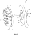
Fig. 5 ] A view for describing a casting step and a molding step in a manufacturing method of the bioelectrode according to the embodiment of the present invention. - [
Fig. 6 ] A view for describing a volume resistivity evaluation test for the bioelectrode according to the embodiment of the present invention. - Hereinafter, an embodiment of the present invention will be described with reference to the drawings.
-
Fig. 1 is a perspective view schematically showing a structure of abioelectrode 1 according to an embodiment of the present invention.Fig. 2 is a side view schematically showing the structure of thebioelectrode 1, andFig. 3 is a plan view schematically showing the structure of thebioelectrode 1.Fig. 4 is an A-A cross-sectional view schematically showing the structure of thebioelectrode 1 shown inFig. 2 . Thebioelectrode 1 according to the embodiment of the present invention includes asupport member 10, anelectrode member 20 of conductive rubber, including a supportedpart 21 that is a member supported by thesupport member 10 and at least oneelectrode part 24 that is a member protruding from the supportedpart 21, and a snap-button-type connector 30 that is provided on thesupport member 10, and that electrically connects theelectrode member 20 to outside. The snap-button-type connector 30 and the supportedpart 21 are integrally molded. - The snap-button-
type connector 30 includes a supported-part-side fitting part 40 provided on a side of the supportedpart 21, and a connection-surface-side fitting part 50 provided on aconnection surface 12 that is an outer side. The supported-part-side fitting part 40 and the supportedpart 21 are integrally molded. - With the
bioelectrode 1, a tip end portion of theelectrode part 24 of theelectrode member 20 contacts a body of a subject, and biosignals from the subject may be detected via theelectrode part 24 of theelectrode member 20. For example, thebioelectrode 1 is a bioelectrode for brain wave detection that detects brain waves by contacting a head of the subject. Thebioelectrode 1 is not limited to brain wave detection, and may also be applied to other devices for detecting biosignals, such as a wearable information appliance. Hereinafter, a structure of thebioelectrode 1 will be specifically described. - As shown in
Figs. 1 to 4 , with respect to thebioelectrode 1, thesupport member 10 has a disk shape or a substantially disk shape, for example. Thesupport member 10 includes asupport surface 11 that is a surface for supporting theelectrode member 20, and aconnection surface 12 facing away from thesupport surface 11, theconnection surface 12 being a surface that is on a side where a connection part (not shown) for enabling electrical connection to a measurement device (not shown) is to be connected. Additionally, the measurement device, not shown, is a device for receiving a biosignal detected by thebioelectrode 1, and for processing, analyzing, or displaying the biosignal that is received, for example. A through hole 13 (Fig. 4 ) penetrating thesupport surface 11 and theconnection surface 12 is formed at a center or substantially at a center of thesupport member 10. Thesupport member 10 supports theelectrode member 20 with thesupport surface 11. - The
support member 10 is formed of an insulating material, and is not electrically connected to theelectrode member 20. For example, thesupport member 10 is formed of silicone rubber. Additionally, a shape of thesupport member 10 may be any shape and is not limited to a specific shape so long as theelectrode member 20 can be supported. - The supported-part-side fitting part 40 (
Fig. 4 ) of the snap-button-type connector 30 is provided at a center or substantially at a center of thesupport surface 11 of thesupport member 10. Details of the supported-part-side fittingpart 40 of the snap-button-type connector 30 will be given later. - Furthermore, the connection-surface-side fitting
part 50 of the snap-button-type connector 30 is provided at a center or substantially at a center of theconnection surface 12 of thesupport member 10. Details of the connection-surface-side fittingpart 50 of the snap-button-type connector 30 will be given later. - With the
bioelectrode 1, theelectrode member 20 includes the supportedpart 21 that is a member to be supported by thesupport member 10, and at least oneelectrode part 24 that is a member protruding from the supportedpart 21. The supportedpart 21 of theelectrode member 20 has a disk shape or a substantially disk shape, for example. The supportedpart 21 includes a supportedsurface 22 that is a surface to be supported by thesupport surface 11 of thesupport member 10, and aprotrusion surface 23 facing away from the supportedsurface 22, theprotrusion surface 23 being a surface from which theelectrode part 24 protrudes. When seen along an axial direction, the shape of the supportedpart 21 is a same or substantially same shape as the shape of thesupport member 10. - The
bioelectrode 1 is provided with a plurality ofelectrode parts 24 on theelectrode member 20, and theelectrode parts 24 protrude in a same or substantially same directions from theprotrusion surface 23 of the supportedpart 21. A tip end of each of theelectrode parts 24 of theelectrode member 20 is formed into a hemispherical or substantially hemispherical shape, for example. Theelectrode parts 24 of theelectrode member 20 protrude from theprotrusion surface 23 of the supportedpart 21 in a form of a brush, for example. - A shape of the
electrode part 24 of theelectrode member 20 is, as a whole, a conical or substantially conical shape that is tapered toward the tip end of theelectrode part 24, for example. Additionally, the shape of theelectrode part 24 of theelectrode member 20 may be a shape that is columnar or substantially columnar and that includes a part that is tapered toward the tip end, and is not limited to a specific shape. - The
electrode member 20 is formed of conductive rubber. The conductive rubber for forming theelectrode member 20 includes silicone rubber and metal particles. For example, the silicone rubber is liquid silicone rubber of a room-temperature curing type, and the metal particles are silver particles. The metal particles may be of a carbonaceous material such as carbon black or carbon nanotube, for example, so long as the metal particles are of a metal material having conductivity. - The liquid silicone rubber of a room-temperature curing type is silicone rubber that is in a state of liquid or paste before curing, and that, normally, becomes a rubber elastic body when a curing reaction proceeds at 20°C to 100°C. The curing reaction may be a curing reaction that gradually proceeds due to moisture (water) in the air, or may be a curing reaction that is caused to swiftly proceed, by mixing a curing agent in a main material, and curing may be performed by any curing reaction. Furthermore, it is possible to use only one type of liquid silicone rubber of a room-temperature curing type, or it is possible to mix and use a plurality of types of liquid silicone rubber of a room-temperature curing type.
- As the silver particles in the conductive rubber, those containing silver powder in an agglomerated form and silver powder in a flake form may be used. Silver powder in an agglomerated form is a plurality of primary particles in a particle form agglomerated into a three-dimensional form, and silver powder in a flake form has a shape that is scale-like. An average particle diameter of silver powder in an agglomerated form and silver powder in a flake form is not limited to a specific value.
- Additionally, the conductive rubber for forming the
electrode member 20 may further contain other components, in addition to components described above, so long as an advantageous effect of the present invention is not impaired. For example, as other components, additives commonly used in rubber industry, such as a reinforcing agent, a filler such as dry silica, an anti-aging agent, a processing aid, or a plasticizer, may be added as appropriate. - As described above, the
electrode member 20 is formed by curing silicone rubber, and has flexibility and elasticity, good adhesion to a body of a subject, is soft on skin and does not cause discomfort even when adhered for a long time, and may maintain stable contact with the body of the subject. - With the
bioelectrode 1, the snap-button-type connector 30 includes the supported-part-sidefitting part 40 provided on the side of the supportedpart 21, and the connection-surface-sidefitting part 50 provided on theconnection surface 12, and the supported-part-sidefitting part 40 and the supportedpart 21 are integrally molded. For example, the snap-button-type connector 30 is formed of stainless steel. Additionally, the snap-button-type connector 30 is not limited to be of a specific material so long as the supported-part-sidefitting part 40 and the connection-surface-sidefitting part 50 are electrically connected. - As shown in
Fig. 4 , with respect to the snap-button-type connector 30, the supported-part-sidefitting part 40 includes a supported-part-side-fitting-part base portion 41, and a protrudingfitting part 44 that is a member protruding from the supported-part-side-fitting-part base portion 41. With respect to the supported-part-sidefitting part 40, the supported-part-side-fitting-part base portion 41 has, for example, a disk shape or a substantially disk shape, and is formed into a dish shape or a substantially dish shape that is shallowly recessed at a center or substantially at a center. The supported-part-side-fitting-part base portion 41 includes aprotrusion surface 42 that is a surface from which the protrudingfitting part 44 protrudes, and an embeddedsurface 43 that faces away from theprotrusion surface 42 and that is to be embedded in the supportedpart 21 of theelectrode member 20. - With respect to the supported-part-side
fitting part 40, the protrudingfitting part 44 protrudes from a center or substantially a center of theprotrusion surface 42 of the supported-part-side-fitting-part base portion 41. The protrudingfitting part 44 has a shape that is bottomed cylindrical or substantially bottomed cylindrical, and afitting part 45 that is annular or substantially annular and that is recessed in a radial direction from an outer peripheral surface of the protrudingfitting part 44 is formed at a tip end of the protrudingfitting part 44. A diameter of the outer peripheral surface of the protrudingfitting part 44 is same or substantially same as a diameter of an inner peripheral surface of the throughhole 13 of thesupport member 10, and the protrudingfitting part 44 is inserted in the throughhole 13 of thesupport member 10. Theprotrusion surface 42 of the supported-part-sidefitting part 40 is disposed on thesupport surface 11 of thesupport member 10, at the center or substantially at the center of thesupport surface 11 of thesupport member 10, with the protrudingfitting part 44 inserted in the throughhole 13 of thesupport member 10. - The supported-part-side
fitting part 40 is integrally molded with the supportedpart 21 of theelectrode member 20. Specifically, the supported-part-sidefitting part 40 is provided at a center or substantially a center of the supportedpart 21 of theelectrode member 20, with the embeddedsurface 43 of the supported-part-side-fitting-part base portion 41 embedded inside the supportedpart 21, on a side of the supportedsurface 22, and the supported-part-side-fitting-part base portion 41 of the supported-part-sidefitting part 40 and the supportedpart 21 of theelectrode member 20 are integrally molded. Additionally, only the embeddedsurface 43 of the supported-part-side-fitting-part base portion 41 is embedded inside the supportedpart 21, on the side of the supportedsurface 22, and theprotrusion surface 42 of the supported-part-side-fitting-part base portion 41 is not embedded inside the supportedpart 21, on the side of the supportedsurface 22. - As shown in
Fig. 4 , with respect to the snap-button-type connector 30, the connection-surface-sidefitting part 50 includes a connection-surface-side-fitting-part base portion 51, and a recessedfitting part 54 that is recessed from the connection-surface-side-fitting-part base portion 51, and that is formed to be capable of being fitted with the protrudingfitting part 44 of the supported-part-sidefitting part 40. With respect to the connection-surface-sidefitting part 50, the connection-surface-side-fitting-part base portion 51 has a disk shape or a substantially disk shape, and is formed into a dish shape or a substantially dish shape that is shallowly recessed at a center or substantially at a center, for example. - The connection-surface-side-fitting-
part base portion 51 includes a recessedsurface 52 that is a surface from which the recessedfitting part 54 is recessed, and a facingsurface 53 that faces away from the recessedsurface 52 and that faces theconnection surface 12 of thesupport member 10. A diameter of the connection-surface-side-fitting-part base portion 51 is same or substantially same as a diameter of the supported-part-side-fitting-part base portion 41. - With respect to the connection-surface-side
fitting part 50, the recessedfitting part 54 is recessed from a center or substantially a center of the recessedsurface 52 of the connection-surface-side-fitting-part base portion 51. The recessedfitting part 54 has a shape that is bottomed cylindrical or substantially bottomed cylindrical, is gradually widened in a radial direction from a base of the recessedfitting part 54 toward a tip end, and is fitted with thefitting part 45 of the protrudingfitting part 44 of the supported-part-sidefitting part 40 at the base of the recessedfitting part 54. - That is, a diameter of the base of the recessed
fitting part 54 is same or substantially same as a diameter of thefitting part 45 of the protrudingfitting part 44 of the supported-part-sidefitting part 40, and the recessedfitting part 54 is fitted, at the center or substantially the center of theconnection surface 12 of thesupport member 10, with thefitting part 45, of the protrudingfitting part 44 of the supported-part-sidefitting part 40, that is inserted in the throughhole 13 of thesupport member 10. In this manner, the supported-part-sidefitting part 40 and the connection-surface-sidefitting part 50 are fixed on thesupport member 10, by the protrudingfitting part 44 being fitted with the recessedfitting part 54 via thesupport member 10 by crimping or the like, for example. That is, the supported-part-sidefitting part 40 and the connection-surface-sidefitting part 50 are fixed on thesupport member 10, by the protrudingfitting part 44 and the recessedfitting part 54 being fitted together in a state where thesupport member 10 is sandwiched between the supported-part-side-fitting-part base portion 41 and the connection-surface-side-fitting-part base portion 51. - The connection-surface-side
fitting part 50 functions as a terminal for electrically connecting thebioelectrode 1 to the measurement device (not shown) described above. For example, the connection-surface-sidefitting part 50 is connected by being fitted with a connection part (not shown), of another snap-button-type connector or the like corresponding to the snap-button-type connector 30, that allows electrical connection to the measurement device (not shown) described above. Additionally, it is enough if the connection-surface-sidefitting part 50 can be electrically connected to outside, to a lead wire, an external appliance, or a measurement appliance, for example, without being limited to the measurement device (not shown). - Next, a manufacturing method of the
bioelectrode 1 having the structure described above will be described. The manufacturing method of thebioelectrode 1 includes a casting step and a molding step. The casting step is a step of stirring conductive rubber and casting the conductive rubber into a shape of theelectrode member 20, and the molding step is a step of cross-linking theelectrode member 20 by placing thesupport member 10 provided with the snap-button-type connector 30 on the supportedpart 21 of theelectrode member 20 that is cast in the casting step, and integrally molding the snap-button-type connector 30 and the supportedpart 21. Hereinafter, the manufacturing method of thebioelectrode 1 will be specifically described. -
Fig. 5 is a view for describing the casting step and the molding step in the manufacturing method of thebioelectrode 1 according to the embodiment of the present invention. As shown inFig. 5 , in the casting step, conductive rubber containing silicone rubber and metal particles is stirred, and the conductive rubber is injected in a mold (cavity) having the shape of theelectrode member 20, and anintermediate product 60 where the supportedpart 21 and theelectrode part 24 of theelectrode member 20 are molded is cast. With theintermediate product 60, the embeddedsurface 43 of the supported-part-sidefitting part 40 of the snap-button-type connector 30 is not embedded in the supportedpart 21 of theelectrode member 20. - Next, as shown in
Fig. 5 , in the molding step, thesupport member 10 in a state where the supported-part-sidefitting part 40 of the snap-button-type connector 30 is fitted, on thesupport surface 11 of thesupport member 10, with the connection-surface-sidefitting part 50 and fixed to thesupport member 10 is placed on the supportedsurface 22 of the supportedpart 21 of theintermediate product 60 that is cast in the mold (cavity). - Next, in the molding step, the
intermediate product 60 is cross-linked in a state where thesupport member 10 is placed on the supportedsurface 22 of the supportedpart 21 of theintermediate product 60. The curing is thereby performed in a state in which the embeddedsurface 43 of the supported-part-side-fitting-part base portion 41 of the supported-part-sidefitting part 40 is embedded inside the supportedpart 21, on the side of the supportedsurface 22, and the supported-part-sidefitting part 40 and the supportedpart 21 are integrally molded. Additionally, theprotrusion surface 42 of the supported-part-side-fitting-part base portion 41 is not embedded inside the supportedpart 21, on the side of the supportedsurface 22. - The
electrode member 20 is molded by curing silicone rubber as a binder in which metal particles are added, and a molding surface layer (not shown) that is a layer with a small amount of metal particles is formed on a surface of theelectrode member 20 that is molded. Contact impedance between the embeddedsurface 43 of the supported-part-side-fitting-part base portion 41 and the supportedpart 21 of theelectrode member 20 is specified not by an apparent contact area, but by an effective contact area, for achieving electrical contact, between the embeddedsurface 43 of the supported-part-side-fitting-part base portion 41 and metal particles in the supportedpart 21. - In a case where a surface of the embedded
surface 43 of the supported-part-side-fitting-part base portion 41 and a surface of the supportedsurface 22 of the supportedpart 21 are in contact, or in other words, in a case where the surfaces are attached without the embeddedsurface 43 of the supported-part-side-fitting-part base portion 41 being embedded in the supportedsurface 22 of the supportedpart 21, the embeddedsurface 43 of the supported-part-side-fitting-part base portion 41 contacts the molding surface layer (not shown), and the contact impedance is increased, and noise that is mixed in a biosignal that is detected is possibly increased, or acquisition of the biosignal is possibly made impossible. - In contrast, the embedded
surface 43 of the supported-part-side-fitting-part base portion 41 of the supported-part-sidefitting part 40 is embedded inside the supportedpart 21, on the side of the supportedsurface 22, and the embeddedsurface 43 contacts the supportedpart 21 on an inner side than the molding surface layer (not shown) without contacting the molding surface layer (not shown) on the surface of the supportedsurface 22 of the supportedpart 21. Accordingly, the contact impedance between theelectrode member 20 and the supported-part-sidefitting part 40 may be reduced, and noise that is mixed in a biosignal that is detected is not increased, and also, acquisition of the biosignal is not made impossible. - Furthermore, according to the manufacturing method of the
bioelectrode 1, the curing is performed in a state in which the embeddedsurface 43 of the supported-part-side-fitting-part base portion 41 of the supported-part-sidefitting part 40 is embedded inside the supportedpart 21, on the side of the supportedsurface 22. Accordingly, the supportedpart 21 of theelectrode member 20 is formed in accordance with asperities of the embeddedsurface 43 of the supported-part-side-fitting-part base portion 41 of the supported-part-sidefitting part 40, and the supportedpart 21 of theelectrode member 20 makes a surface contact with the asperities of the embeddedsurface 43 of the supported-part-side-fitting-part base portion 41. - The effective contact area that is a contact area between the embedded
surface 43 of the supported-part-side-fitting-part base portion 41 and the metal particles in the supportedpart 21 may thus be increased, and as a result, the contact impedance between theelectrode member 20 and the supported-part-sidefitting part 40 may be reduced. Furthermore, because the supported-part-sidefitting part 40 and the supportedpart 21 are integrally molded, an interface between the embeddedsurface 43 of the supported-part-side-fitting-part base portion 41 and the metal particles in the supportedpart 21 does not move, and stable contact impedance may be achieved. - As described above, with the
bioelectrode 1 according to the embodiment of the present invention, the snap-button-type connector 30 includes the supported-part-sidefitting part 40 provided on the side of the supportedpart 21, and the connection-surface-sidefitting part 50 provided on theconnection surface 12. Due to the protrudingfitting part 44 of the supported-part-sidefitting part 40 being inserted in the throughhole 13 of thesupport member 10 and thefitting part 45 being fitted with the base of the recessedfitting part 54 of the connection-surface-sidefitting part 50, thesupport member 10 and theelectrode member 20 are fixed, and the supported-part-sidefitting part 40 and the supportedpart 21 are integrally molded. - Accordingly, the
bioelectrode 1 may be electrically connected to the measurement device (not shown) described above via the connection-surface-sidefitting part 50, due to the connection-surface-sidefitting part 50 being fitted with a connection part (not shown) of another snap-button-type connector or the like, of the measurement device (not shown) described above, corresponding to the snap-button-type connector 30. A connection portion between an electrode portion and a connection wire portion may thus be prevented from becoming unstable, and the connection portion between the electrode portion and the connection wire portion may be prevented from coming apart due to movement of the subject or the like, and the electrode portion and the connection wire portion may be stably connected. - Furthermore, with the
bioelectrode 1, theelectrode part 24 of theelectrode member 20 is formed of conductive rubber, and has desirable elasticity such that no discomfort is felt by the subject, and also, theelectrode part 24 may be evenly adhered to a target part of the subject. Accordingly, a reinforcing member such as a core material for giving elasticity to theelectrode part 24 of theelectrode member 20 is not necessary. Furthermore, theelectrode part 24 of theelectrode member 20 may be formed with only conductive rubber, and a structure of theelectrode member 20 is not complex and manufacturing is facilitated. Moreover, with thebioelectrode 1, the snap-button-type connector 30 is formed of stainless steel, and thus has good conductivity and is easily handled, and the electrode portion and the connection wire portion may be stably connected at a low cost. - Next, an evaluation test for volume resistivity of the
bioelectrode 1 according to the embodiment of the present invention will be described. The present inventor fabricated thebioelectrode 1 according to the embodiment of the present invention described above (example), and performed a volume resistivity evaluation test on thebioelectrode 1. As shown inFig. 6 , the volume resistivity evaluation test was performed by measuring volume resistivity of the example by using an LCR meter. Specifically, the bioelectrode 1 (example) was placed on a gold sheet and was connected with Kelvin clips, and the volume resistivity was measured by the LCR meter. Additionally, a following LCR meter was used as the LCR meter. - Furthermore, with respect to the example, conductive rubber of components indicated in Table 1 below was centrifugally stirred, and was injected into a mold (cavity). Then, the
support member 10 in a state where the supported-part-sidefitting part 40 of the snap-button-type connector 30 was fitted, on thesupport surface 11 of thesupport member 10, with the connection-surface-sidefitting part 50 and fixed to thesupport member 10 was placed on the supportedsurface 22 of the supportedpart 21 of theintermediate product 60 that was cast in the mold (cavity). Next, theintermediate product 60 was cross-linked under cross-linking conditions indicated in Table 2, in a state where thesupport member 10 was placed on the supportedsurface 22 of the supportedpart 21 of theintermediate product 60. Then, brine treatment was performed in an autoclave under brine treatment conditions indicated in Table 3, and thebioelectrode 1 of the example was fabricated.[Table 1] Used product (used material) Added amount Liquid silicone rubber of room-temperature curing type Manufactured by Shin-Etsu Chemical Co., Ltd. KE-106 100phr Curing agent Manufactured by Shin-Etsu Chemical Co., Ltd. CAT-RG 10phr Silver particle Manufactured by DOWA HOLDINGS CO., LTD. G-35 165phr Manufactured by DOWA HOLDINGS CO., LTD. FA-2-3 165phr Dispersing agent Manufactured by Shin-Etsu Chemical Co., Ltd. KF-6106 10phr Manufactured by Shin-Etsu Chemical Co., Ltd. KF-6015 10phr Table 2] Example Primary cross-linking 150°C, 3min Secondary cross-linking 150°C, 30min Table 3] Example Brine concentration 10 % Immersion time 1 hr Brine temperature 121°C Pressure 0.1 MPaG - In the present evaluation test, the volume resistivity was measured in the manner described above for the example by using 10 samples. A test result is an average value of measured values for the 10 samples. The measurement result of the volume resistivity for the example was 0.98 Ω. In this manner, it was confirmed that the
electrode member 20 is electrically connected via the snap-button-type connector 30. - Heretofore, an embodiment of the present invention has been described, but the present invention is not limited to the embodiment of the present invention described above, and includes any mode within the concept of the present invention and the scope of the claims. Furthermore, structures may be selectively combined as appropriate to achieve at least one of objects and advantageous effects described above. For example, the shape, material, arrangement, size and the like of each structural element in the embodiment described above may be changed as appropriate according to a specific usage mode of the present invention.
- For example, the
support member 10 is not limited to the shape described above, and may take other shapes. Likewise, theelectrode member 20 is not limited to the shape described above, and may take other shapes. - Furthermore, the supported-part-side
fitting part 40 and the connection-surface-sidefitting part 50 may both be formed from a same material using the stainless steel mentioned above, or may be formed from different materials. In the case of forming the supported-part-sidefitting part 40 and the connection-surface-sidefitting part 50 from different materials, the supported-part-sidefitting part 40 and the connection-surface-sidefitting part 50 may be formed from materials having conductivity and different from stainless steel. As the materials having conductivity for the supported-part-sidefitting part 40 and the connection-surface-sidefitting part 50, different metals such as copper and aluminum may be used, for example. The materials for the supported-part-sidefitting part 40 and the connection-surface-sidefitting part 50 are not limited to the above, and materials having conductivity, such as conductive rubber, may be used. - Furthermore, a case has been described where the supported-part-side
fitting part 40 and the connection-surface-sidefitting part 50 are fixed to thesupport member 10 by being fitted together by crimping or the like, for example. However, the present invention is not limited to such a case, and the supported-part-sidefitting part 40 may be provided on theelectrode member 20 and the connection-surface-sidefitting part 50 may be provided on thesupport member 10, and the supported-part-sidefitting part 40 and the connection-surface-sidefitting part 50 may be fixed to thesupport member 10 by being fitted together by crimping or the like, for example. - Moreover, a case has been described where only the embedded
surface 43 of the supported-part-side-fitting-part base portion 41 is provided embedded in the supportedsurface 22 of the supportedpart 21. However, the present invention is not limited to such a case, and all of the supported-part-side-fitting-part base portion 41 may be embedded in the supportedsurface 22 of the supportedpart 21. Furthermore, the connection-surface-sidefitting part 50 may be provided, at the center or substantially the center of theconnection surface 12 of thesupport member 10, with an outer edge of the facingsurface 53 of the connection-surface-sidefitting part 50 adhered to theconnection surface 12 of thesupport member 10 with an adhesive or the like, or may be provided partly being embedded inside theconnection surface 12 of thesupport member 10. -
- 1
- bioelectrode,
- 10
- support member,
- 11
- support surface,
- 12
- connection surface,
- 13
- through hole,
- 20
- electrode member,
- 21
- supported part,
- 22
- supported surface,
- 23
- protrusion surface,
- 24
- electrode part,
- 30
- snap-button-type connector,
- 40
- supported-part-side fitting part,
- 41
- supported-part-side-fitting-part base portion,
- 42
- protrusion surface,
- 43
- embedded surface,
- 44
- protruding fitting part,
- 45
- fitting part,
- 50
- connection-surface-side fitting part,
- 51
- connection-surface-side-fitting-part base portion,
- 52
- recessed surface,
- 53
- facing surface,
- 54
- recessed fitting part
Claims (6)
- A bioelectrode characterized by comprising:a support member;an electrode member of conductive rubber, including a supported part that is a member to be supported by the support member, and at least one electrode part that is a member protruding from the supported part; anda snap-button-type connector that is provided on the support member, and that electrically connects the electrode member to outside, whereinthe snap-button-type connector and the supported part are integrally molded.
- The bioelectrode according to claim 1, characterized in that:the snap-button-type connector includes a supported-part-side fitting part provided on a side of the supported part, and an outer-side fitting part provided on an outer side,the supported-part-side fitting part includes a supported-part-side-fitting-part base portion, and a protruding fitting part that is a member protruding from the supported-part-side-fitting-part base portion,the outer-side fitting part includes an outer-side-fitting-part base portion, and a recessed fitting part that is recessed from the outer-side-fitting-part base portion, and that is fitted with the protruding fitting part of the supported-part-side fitting part,the supported-part-side fitting part and the outer-side fitting part are fixed to the support member by the protruding fitting part being fitted with the recessed fitting part via the support member, andthe supported-part-side fitting part and the supported part are integrally molded.
- The bioelectrode according to claim 1 or 2, characterized in that the snap-button-type connector and the supported part are integrally molded with the support member.
- The bioelectrode according to any one of claims 1 to 3, characterized in that the electrode member is molded from conductive rubber containing silicone rubber and metal particles.
- The bioelectrode according to any one of claims 1 to 4, characterized in that the snap-button-type connector is stainless steel.
- A manufacturing method of a bioelectrode including a support member, an electrode member of conductive rubber, including a supported part that is a member to be supported by the support member and at least one electrode part that is a member protruding from the supported part, and a snap-button-type connector that is provided on the support member and that electrically connects the electrode member to outside, the manufacturing method being characterized by comprising:a casting step of casting the conductive rubber into a shape of the electrode member; anda molding step of cross-linking the electrode member in a state in which the support member provided with the snap-button-type connector is placed on the supported part of the electrode member that is cast in the casting step, and integrally molding the snap-button-type connector and the supported part.
Applications Claiming Priority (2)
| Application Number | Priority Date | Filing Date | Title |
|---|---|---|---|
| JP2018231021 | 2018-12-10 | ||
| PCT/JP2019/045733 WO2020121777A1 (en) | 2018-12-10 | 2019-11-22 | Biological electrode and biological electrode production method |
Publications (2)
| Publication Number | Publication Date |
|---|---|
| EP3895609A1 true EP3895609A1 (en) | 2021-10-20 |
| EP3895609A4 EP3895609A4 (en) | 2022-08-31 |
Family
ID=71076354
Family Applications (1)
| Application Number | Title | Priority Date | Filing Date |
|---|---|---|---|
| EP19897102.0A Withdrawn EP3895609A4 (en) | 2018-12-10 | 2019-11-22 | BIOLOGICAL ELECTRODE AND METHOD FOR PRODUCING BIOLOGICAL ELECTRODE |
Country Status (5)
| Country | Link |
|---|---|
| US (1) | US20210338129A1 (en) |
| EP (1) | EP3895609A4 (en) |
| JP (1) | JPWO2020121777A1 (en) |
| CN (1) | CN112888365A (en) |
| WO (1) | WO2020121777A1 (en) |
Family Cites Families (11)
| Publication number | Priority date | Publication date | Assignee | Title |
|---|---|---|---|---|
| JPS5283595U (en) * | 1975-12-19 | 1977-06-22 | ||
| US4207904A (en) * | 1977-01-28 | 1980-06-17 | Greene Ronald W | Constant power density electrode adapted to be useful in bio-medical applications |
| WO2006046325A1 (en) * | 2004-10-29 | 2006-05-04 | Ngk Spark Plug Co., Ltd. | Liquid state detecting sensor |
| JP5803186B2 (en) * | 2011-03-23 | 2015-11-04 | ソニー株式会社 | Biological signal detection electrode and biological signal detection apparatus |
| JP5842198B2 (en) * | 2011-11-30 | 2016-01-13 | 公益財団法人ヒューマンサイエンス振興財団 | Electroencephalogram measurement electrode, electroencephalogram measurement member, and electroencephalogram measurement apparatus |
| JP2013144051A (en) | 2012-01-16 | 2013-07-25 | Sony Corp | Electrode for acquiring biological signal |
| JP2013248306A (en) | 2012-06-04 | 2013-12-12 | Dejitekkusu Kenkyusho:Kk | Bioelectrode for measuring brain wave |
| US9486618B2 (en) * | 2013-08-27 | 2016-11-08 | Halo Neuro, Inc. | Electrode system for electrical stimulation |
| WO2016080804A1 (en) * | 2014-11-20 | 2016-05-26 | Samsung Electronics Co., Ltd. | Apparatus for measuring bioelectrical signals |
| CN107374622B (en) * | 2017-06-16 | 2020-08-18 | 华南理工大学 | A flexible dry electrode for collecting EEG signals and preparation method thereof |
| CN108652620B (en) * | 2018-05-30 | 2024-08-23 | 华南理工大学 | Flexible semi-dry multilayer structure electrode for collecting EEG signals |
-
2019
- 2019-11-22 CN CN201980067887.7A patent/CN112888365A/en active Pending
- 2019-11-22 JP JP2020515985A patent/JPWO2020121777A1/en not_active Withdrawn
- 2019-11-22 WO PCT/JP2019/045733 patent/WO2020121777A1/en not_active Ceased
- 2019-11-22 US US17/286,190 patent/US20210338129A1/en not_active Abandoned
- 2019-11-22 EP EP19897102.0A patent/EP3895609A4/en not_active Withdrawn
Also Published As
| Publication number | Publication date |
|---|---|
| WO2020121777A1 (en) | 2020-06-18 |
| EP3895609A4 (en) | 2022-08-31 |
| US20210338129A1 (en) | 2021-11-04 |
| CN112888365A (en) | 2021-06-01 |
| JPWO2020121777A1 (en) | 2021-10-21 |
Similar Documents
| Publication | Publication Date | Title |
|---|---|---|
| EP3868290A1 (en) | Bioelectrode and bioelectrode production method | |
| EP3482683B1 (en) | Bioelectrode and method of manufacturing the bioelectrode | |
| CN104665806A (en) | Electrode, biosignal detecting device and method of measuring a biosignal | |
| EP4208095B1 (en) | Soft and dry electrode | |
| JPH0889486A (en) | Multi-sensor | |
| CN108472846A (en) | Integral sensor for bioelectrode and the method for production | |
| CN114901144B (en) | Biological electrodes | |
| EP3868289B1 (en) | Bioelectrode and bioelectrode production method | |
| US20210338129A1 (en) | Bioelectrode and manufacturing method of bioelectrode | |
| KR100773447B1 (en) | Biological electrodes and biosignal measuring devices | |
| CN114760923A (en) | Method for manufacturing bioelectrode | |
| EP3695780A1 (en) | Brain wave detection bioelectrode | |
| CN111096754B (en) | Biological sensor | |
| US20240081714A1 (en) | Biological electrode | |
| KR101862728B1 (en) | Member being connected to living body and generating method using same, electrode for measuring bio signal using said member and measurement method using same | |
| WO2020246358A1 (en) | Bioelectrode | |
| US20150272459A1 (en) | Sensor probe assembly | |
| US20240138738A1 (en) | Biopotential electrode body and biopotential sensor | |
| US20260041352A1 (en) | Electrode member and bioelectric signal measuring electrode | |
| KR20230133513A (en) | Electrode for Electroencephalograph | |
| KR20250043702A (en) | Electrode for Electroencephalograph | |
| WO2025107089A1 (en) | Active soft & dry electrode | |
| US9354267B1 (en) | Sensor probe assembly | |
| JPS6323052Y2 (en) | ||
| JPH04131212U (en) | Probe attachment device for electroencephalogram measurement |
Legal Events
| Date | Code | Title | Description |
|---|---|---|---|
| STAA | Information on the status of an ep patent application or granted ep patent |
Free format text: STATUS: THE INTERNATIONAL PUBLICATION HAS BEEN MADE |
|
| PUAI | Public reference made under article 153(3) epc to a published international application that has entered the european phase |
Free format text: ORIGINAL CODE: 0009012 |
|
| STAA | Information on the status of an ep patent application or granted ep patent |
Free format text: STATUS: REQUEST FOR EXAMINATION WAS MADE |
|
| 17P | Request for examination filed |
Effective date: 20210422 |
|
| AK | Designated contracting states |
Kind code of ref document: A1 Designated state(s): AL AT BE BG CH CY CZ DE DK EE ES FI FR GB GR HR HU IE IS IT LI LT LU LV MC MK MT NL NO PL PT RO RS SE SI SK SM TR |
|
| DAV | Request for validation of the european patent (deleted) | ||
| DAX | Request for extension of the european patent (deleted) | ||
| REG | Reference to a national code |
Ref country code: DE Ref legal event code: R079 Free format text: PREVIOUS MAIN CLASS: A61B0005047800 Ipc: A61B0005268000 |
|
| A4 | Supplementary search report drawn up and despatched |
Effective date: 20220728 |
|
| RIC1 | Information provided on ipc code assigned before grant |
Ipc: A61B 5/291 20210101ALI20220722BHEP Ipc: A61B 5/268 20210101AFI20220722BHEP |
|
| STAA | Information on the status of an ep patent application or granted ep patent |
Free format text: STATUS: THE APPLICATION IS DEEMED TO BE WITHDRAWN |
|
| 18D | Application deemed to be withdrawn |
Effective date: 20230629 |