EP3895558A1 - Aerosol generating article and system comprising composite heat source - Google Patents
Aerosol generating article and system comprising composite heat source Download PDFInfo
- Publication number
- EP3895558A1 EP3895558A1 EP21735837.3A EP21735837A EP3895558A1 EP 3895558 A1 EP3895558 A1 EP 3895558A1 EP 21735837 A EP21735837 A EP 21735837A EP 3895558 A1 EP3895558 A1 EP 3895558A1
- Authority
- EP
- European Patent Office
- Prior art keywords
- combustible
- heat source
- aerosol generating
- generating article
- wick
- Prior art date
- Legal status (The legal status is an assumption and is not a legal conclusion. Google has not performed a legal analysis and makes no representation as to the accuracy of the status listed.)
- Granted
Links
Images




Classifications
-
- A—HUMAN NECESSITIES
- A24—TOBACCO; CIGARS; CIGARETTES; SIMULATED SMOKING DEVICES; SMOKERS' REQUISITES
- A24F—SMOKERS' REQUISITES; MATCH BOXES; SIMULATED SMOKING DEVICES
- A24F40/00—Electrically operated smoking devices; Component parts thereof; Manufacture thereof; Maintenance or testing thereof; Charging means specially adapted therefor
- A24F40/40—Constructional details, e.g. connection of cartridges and battery parts
- A24F40/44—Wicks
-
- A—HUMAN NECESSITIES
- A24—TOBACCO; CIGARS; CIGARETTES; SIMULATED SMOKING DEVICES; SMOKERS' REQUISITES
- A24D—CIGARS; CIGARETTES; TOBACCO SMOKE FILTERS; MOUTHPIECES OF CIGARS OR CIGARETTES; MANUFACTURE OF TOBACCO SMOKE FILTERS OR MOUTHPIECES
- A24D1/00—Cigars; Cigarettes
- A24D1/22—Cigarettes with integrated combustible heat sources, e.g. with carbonaceous heat sources
-
- A—HUMAN NECESSITIES
- A24—TOBACCO; CIGARS; CIGARETTES; SIMULATED SMOKING DEVICES; SMOKERS' REQUISITES
- A24D—CIGARS; CIGARETTES; TOBACCO SMOKE FILTERS; MOUTHPIECES OF CIGARS OR CIGARETTES; MANUFACTURE OF TOBACCO SMOKE FILTERS OR MOUTHPIECES
- A24D1/00—Cigars; Cigarettes
- A24D1/02—Cigars; Cigarettes with special covers
-
- A—HUMAN NECESSITIES
- A24—TOBACCO; CIGARS; CIGARETTES; SIMULATED SMOKING DEVICES; SMOKERS' REQUISITES
- A24F—SMOKERS' REQUISITES; MATCH BOXES; SIMULATED SMOKING DEVICES
- A24F40/00—Electrically operated smoking devices; Component parts thereof; Manufacture thereof; Maintenance or testing thereof; Charging means specially adapted therefor
- A24F40/40—Constructional details, e.g. connection of cartridges and battery parts
-
- C—CHEMISTRY; METALLURGY
- C10—PETROLEUM, GAS OR COKE INDUSTRIES; TECHNICAL GASES CONTAINING CARBON MONOXIDE; FUELS; LUBRICANTS; PEAT
- C10L—FUELS NOT OTHERWISE PROVIDED FOR; NATURAL GAS; SYNTHETIC NATURAL GAS OBTAINED BY PROCESSES NOT COVERED BY SUBCLASSES C10G OR C10K; LIQUIFIED PETROLEUM GAS; USE OF ADDITIVES TO FUELS OR FIRES; FIRE-LIGHTERS
- C10L11/00—Fire-lighters
- C10L11/04—Fire-lighters consisting of combustible material
-
- C—CHEMISTRY; METALLURGY
- C10—PETROLEUM, GAS OR COKE INDUSTRIES; TECHNICAL GASES CONTAINING CARBON MONOXIDE; FUELS; LUBRICANTS; PEAT
- C10L—FUELS NOT OTHERWISE PROVIDED FOR; NATURAL GAS; SYNTHETIC NATURAL GAS OBTAINED BY PROCESSES NOT COVERED BY SUBCLASSES C10G OR C10K; LIQUIFIED PETROLEUM GAS; USE OF ADDITIVES TO FUELS OR FIRES; FIRE-LIGHTERS
- C10L2200/00—Components of fuel compositions
- C10L2200/02—Inorganic or organic compounds containing atoms other than C, H or O, e.g. organic compounds containing heteroatoms or metal organic complexes
- C10L2200/0204—Metals or alloys
- C10L2200/0213—Group II metals: Be, Mg, Ca, Sr, Ba, Ra, Zn, Cd, Hg
-
- C—CHEMISTRY; METALLURGY
- C10—PETROLEUM, GAS OR COKE INDUSTRIES; TECHNICAL GASES CONTAINING CARBON MONOXIDE; FUELS; LUBRICANTS; PEAT
- C10L—FUELS NOT OTHERWISE PROVIDED FOR; NATURAL GAS; SYNTHETIC NATURAL GAS OBTAINED BY PROCESSES NOT COVERED BY SUBCLASSES C10G OR C10K; LIQUIFIED PETROLEUM GAS; USE OF ADDITIVES TO FUELS OR FIRES; FIRE-LIGHTERS
- C10L2200/00—Components of fuel compositions
- C10L2200/02—Inorganic or organic compounds containing atoms other than C, H or O, e.g. organic compounds containing heteroatoms or metal organic complexes
- C10L2200/0254—Oxygen containing compounds
-
- C—CHEMISTRY; METALLURGY
- C10—PETROLEUM, GAS OR COKE INDUSTRIES; TECHNICAL GASES CONTAINING CARBON MONOXIDE; FUELS; LUBRICANTS; PEAT
- C10L—FUELS NOT OTHERWISE PROVIDED FOR; NATURAL GAS; SYNTHETIC NATURAL GAS OBTAINED BY PROCESSES NOT COVERED BY SUBCLASSES C10G OR C10K; LIQUIFIED PETROLEUM GAS; USE OF ADDITIVES TO FUELS OR FIRES; FIRE-LIGHTERS
- C10L2230/00—Function and purpose of a components of a fuel or the composition as a whole
- C10L2230/06—Firelighters or wicks, as additive to a solid fuel
-
- C—CHEMISTRY; METALLURGY
- C10—PETROLEUM, GAS OR COKE INDUSTRIES; TECHNICAL GASES CONTAINING CARBON MONOXIDE; FUELS; LUBRICANTS; PEAT
- C10L—FUELS NOT OTHERWISE PROVIDED FOR; NATURAL GAS; SYNTHETIC NATURAL GAS OBTAINED BY PROCESSES NOT COVERED BY SUBCLASSES C10G OR C10K; LIQUIFIED PETROLEUM GAS; USE OF ADDITIVES TO FUELS OR FIRES; FIRE-LIGHTERS
- C10L2270/00—Specifically adapted fuels
- C10L2270/08—Specifically adapted fuels for small applications, such as tools, lamp oil, welding
Definitions
- the disclosure relates to an aerosol generating article including a composite heat source.
- An aerosol generating article according to embodiments may overcome technical shortcomings of the related art.
- a first aspect of the present disclosure may provide an aerosol generating article, including: a first portion including a composite heat source, a second portion adjacent to the first portion and including at least one of an aerosol generating material and a tobacco material; a third portion including a cooling material; and a fourth portion including a filter material, wherein the first portion, the second portion, the third portion, and the fourth portion are sequentially arranged with reference to a longitudinal direction of the aerosol generating article, and the composite heat source includes a combustible heat source and a combustible wick inserted into the combustible heat source.
- heat generated by a composite heat source may be efficiently transferred to an aerosol generating substrate.
- Effects of the disclosure are not limited thereto, and may include all effects that may be derived from the following configurations.
- a first aspect of the disclosure may provide an aerosol generating article, including: a first portion including a composite heat source; a second portion adjacent to the first portion and including at least one of an aerosol generating material and a tobacco material; a third portion including a cooling material; and a fourth portion including a filter material, wherein the first portion, the second portion, the third portion, and the fourth portion are sequentially arranged along a longitudinal direction of the aerosol generating article, and the composite heat source includes a combustible heat source, and a combustible wick inserted into the combustible heat source.
- the combustible wick may include a combustible body soaked with alcohol, a solid fuel, or a metal wire.
- a combustion rate of the combustible wick when the first portion is combusted, may be greater than a combustion rate of the combustible heat source.
- the combustible wick when the first portion is combusted, the combustible wick may be removed, and an air flow passage may be formed in the combustible heat source.
- the aerosol generating article may further include a first wrapper surrounding the first portion and the second portion.
- the combustible wick is coaxially arranged in a central portion of the combustible heat source, and the combustible wick may have a uniform diameter in a longitudinal direction of the aerosol generating article.
- the combustible wick includes a first region and a second region, the first region and the second region being physically connected to each other, and the first region may have a uniform diameter in the longitudinal direction of the aerosol generating article, and the second region may have a diameter increasing in the longitudinal direction of the aerosol generating article.
- the combustible wick may include magnesium ribbon.
- a second aspect of the disclosure may provide an aerosol generating system, in which an aerosol is generated by ignition of the first portion of the aerosol generating article according to the first aspect.
- the combustible wick may include a combustible body soaked with alcohol, a solid fuel, or a metal wire.
- a combustion rate of the combustible wick may be greater than a combustion rate of the combustible heat source.
- the combustible wick may be removed, and an air flow passage may be formed in the combustible heat source.
- a third aspect of the inventive concept may provide a composite heat source for the aerosol generating article, including: a combustible heat source; and a combustible wick inserted into the combustible heat source, wherein the combustible wick may provide a composite heat source including a combustible body soaked with alcohol, a solid fuel, or a metal wire.
- a combustion rate of the combustible wick may be greater than a combustion rate of the combustible source.
- a and/or B indicates at least any one of A and B.
- on ⁇ indicates that a component is on a surface of another component, and also includes cases in which the component contacts the other component or the component is above the other component without contact.
- a longitudinal direction of an aerosol generating article indicates a direction in which a length of the aerosol generating article extends or a direction in which combustion proceeds when the aerosol generating article is combusted.
- FIG. 1 is a schematic diagram of a configuration of an aerosol generating article 100 according to embodiments.
- the aerosol generating article 100 including a first portion 110 that includes a composite heat source, a second portion 120 that is adjacent to the first portion 110 and includes at least one of an aerosol generating material and a tobacco material, a third portion 130 including a cooling material, and a fourth portion 140 including a filter material. Also, in some embodiments, the aerosol generating article 100 may further include a first wrapper 150 and a second wrapper 160.
- the first portion 110, the second portion 120, the third portion 130, and the fourth portion 140 may be sequentially arranged along a longitudinal direction of the aerosol generating article 100.
- Heat generated from the composite heat source arranged in the first portion 110 may be delivered to the second portion 120. Aerosol generated from the second portion 120 due to the heat may be delivered to a user through the third portion 130 and the fourth portion 140.
- the first portion 110 may include the composite heat source.
- the composite heat source may include a combustible heat source and a combustible wick.
- the combustible heat source may include a heat source including carbon.
- the combustible wick may include a combustible body soaked with alcohol, a solid fuel, or a metal wire.
- the composite heat source may be included in the aerosol generating article, and as the heat generated due to the composite heat source is delivered to an aerosol generating material in the aerosol generating article, aerosol may be generated.
- the second portion 120 may be adjacent to the first portion 110.
- the first portion 110 may be at an upstream of the aerosol generating article 100, and compared to the first portion 110, the second portion 120 may be at a downstream of the aerosol generating article 100.
- upstream and downstream when a user puffs air by using the aerosol generating article, a portion into which the air flows from the outside of the aerosol generating article is “upstream”, and a portion from which the air flows to the outside of the aerosol generating article is “downstream”.
- upstream and downstream are used to indicate relative positions or directions of portions or segments included in the aerosol generating article.
- the second portion 120 may include at least one of the aerosol generating material and the tobacco material.
- the tobacco material may include, for example, at least one of shredded pipe tobacco, reconstituted pipe tobacco leaves, tobacco leaves, expanded tobacco, and nicotine extract.
- the tobacco material may include nicotine.
- the aerosol generating material may include at least one of glycerin, propylene glycol, ethylene glycol, dipropylene glycol, diethylene glycol, triethylene glycol, tetraethylene glycol, and oleyl alcohol, but it is not limited thereto.
- the second portion 120 may include the reconstituted pipe tobacco leaves soaked with glycerin.
- the composite heat source of the first portion 110 When the composite heat source of the first portion 110 is ignited, the heat generated from the first portion 110 may be delivered to the second portion 120, and the aerosol may be generated from the reconstituted pipe tobacco leaves soaked with glycerin.
- the disclosure is not necessarily limited to the descriptions.
- the third portion 130 may include the cooling material, which cools an air flow that passes through the first portion 110 and the second portion 120.
- the third portion 130 may include a polymer material or a biodegradable polymer material, configured to cool the aerosol.
- the third portion 130 may include pure polylactic acid alone, but the material for forming the cooling segment is not limited thereto.
- the third portion 130 may include a cellulose acetate filter having a plurality of holes.
- the third portion 130 is not limited to the above-described example and is not limited as long as the cooling segment cools the aerosol.
- the third portion 130 may include a tube filter or a base paper filter that includes a hollow.
- the fourth portion 140 may include a cellulose acetate filter. Shapes of the fourth portion 140 are not limited.
- the fourth portion 140 may include a cylinder-type rod or a tube-type rod having a hollow inside. Also, the fourth portion 140 may include a recess-type rod. When the fourth portion 140 includes a plurality of segments, at least one of the plurality of segments may have a different shape.
- the fourth portion 140 may be formed to generate flavors. For example, a flavoring liquid may be injected onto the fourth portion 140, or an additional fiber coated with a flavoring liquid may be inserted into the fourth portion 140.
- the first portion 110 may have a length from about 8 mm to about 12 mm
- the second portion 120 may have a length from about 10 mm to about 14 mm.
- the disclosure is not necessarily limited to the descriptions.
- the aerosol generating article 100 may further include at least one of the first wrapper 150 and the second wrapper 160.
- the first wrapper 150 may surround the first portion 110 and the second portion 120.
- the first wrapper 150 may include, for example, a heat-conductive wrapper. Desirably, the first wrapper 150 may include an aluminum thin film.
- the first wrapper 150 may have, for example, a heat conductivity from about 50 W ⁇ m -1 /K -1 to about 500 W ⁇ m -1 /K -1 .
- the second wrapper 160 may surround the first portion 110, the second portion 120, the third portion 130, and the fourth portion 140.
- the second wrapper 160 may include, for example, a sheet of cellulose paper. However, the disclosure is not necessarily limited thereto.
- the aerosol generating article 100 may further include a barrier (not shown) arranged between the first portion 110 and the second portion 120.
- the barrier may reduce transfer of harmful gas, which is generated from the first portion 110, to the second portion 120, the third portion 130, or the fourth portion 140.
- the barrier may include, for example, a metal material. Accordingly, the user may puff required components alone in the form of aerosol.
- FIG. 2A is a diagram of a configuration of a composite heat source 200 according to an embodiment.
- the composite heat source 200 may have a cylinder shape.
- the shape of the composite heat source 200 is not necessarily limited to the descriptions, and the disclosure may include all of well-known shapes in the field.
- the composite heat source 200 may include a combustible heat source 210 and a combustible wick 220.
- the combustible heat source 210 may include, for example, a heat source including carbon.
- the combustible wick 220 may include a combustible body soaked with alcohol, a solid fuel, or a metal wire.
- the combustible body soaked with alcohol may include, for example, yarn, thread, paper, woodstick, or the like soaked with ethanol.
- the solid fuel may include, for example, an ignition support material such as solid methyl alcohol.
- the metal wire may include, for example, a magnesium ribbon.
- the combustible wick 220 may have a combustion rate that is greater than that of the combustible heat source 210.
- the combustible wick 220 may support ignition or combustion of the combustible heat source 210.
- the combustible wick 220 may be removed during combustion.
- the combustible wick 220 may be inserted into a center portion of the combustible heat source 210.
- a passage extending in a longitudinal direction of the aerosol generating article may be formed in the center portion of the combustible heat source 210.
- the combustible wick 220 may be coaxially arranged in the center portion of the combustible heat source 210.
- the combustible wick 220 may have a diameter d1.
- the diameter d1 of the combustible wick 220 may be from about 1/10 to about 1/2 of the diameter of the composite heat source 200.
- a weight of the solid fuel or the metal wire included in the composite heat source may be adjusted.
- the combustible wick 220 may have the diameter d1, which is uniform, in the longitudinal direction of the aerosol generating article or a longitudinal direction of the composite heat source 200.
- the combustible wick 220 is combusted and removed, and therefore, after a certain time period, an air flow passage may be formed in a center portion of the composite heat source 200.
- combustion of the combustible heat source 210 may be further promoted.
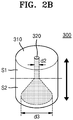
- FIG. 2B is a diagram of a configuration of a composite heat source 300 according to another embodiment.
- the composite heat source 300 in FIG. 2B may include a first region S1 and a second region S2 according to a diameter of the combustible wick 320.
- the composite heat source 300 may include a combustible heat source 310 and the combustible wick 320.
- the combustible wick 320 may be inserted into a center portion of the combustible heat source 310.
- the composite heat source 300 may be divided into the first region S1 and the second region S2.
- the first region S1 and the second region S2 may be physically connected to each other.
- the first region S1 may have a diameter d2, which is uniform, in the longitudinal direction of the aerosol generating article.
- the second region S2 may have a diameter d3 increasing in the longitudinal direction of the aerosol generating article. Accordingly, the diameter d3 may be equal to or greater than the diameter d2.
- the composite heat source 300 according to the embodiment in FIG. 2B may include a greater number of combustible wicks 320 compared to the composite heat source 200 according to the embodiment in FIG. 2A . Accordingly, combustion of the composite heat source 300 according to the embodiment in FIG. 2B may be promoted.
- a combustion rate of the combustible wick 320 may be greater than a combustion rate of the combustible heat source 310.
- the combustible wick 320 may be ignited, combusted, and removed.
- the combustible wick 320 may be removed, and an air flow passage may be formed in the center portion of the combustible heat source 310. Accordingly, the air flow passage may broaden from the first region S1 to the second region S2. Accordingly, air may be more easily introduced from the outside of the aerosol generating article to the inside thereof.
- a surface area of the combustible heat source 310 contacting the external air further increases, and thus, combustion of the combustible heat source 310 may be further promoted.
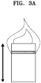
- FIG. 3A is a diagram showing a state in which a combustible heat source is ignited and starts combustion.
- FIG. 3B is a diagram showing a state in which a composite heat source 400 according to an embodiment is ignited and starts combustion.
- the composite heat source 400 in FIG. 3B may be the composite heat source 200 in FIG. 2A .
- the composite heat source 400 may include a combustible heat source 410 and a combustible wick 420. After the composite heat source 400 is ignited and combusted to a certain degree, the combustible heat source 410 and the combustible wick 420 may be partially or entirely combusted and removed. As a combustion rate of the combustible wick 420 is greater than a combustion rate of the combustible heat source 410, it may be seen that a combustion portion in a center portion of the combustible heat source 410 is formed in a greater depth compared to other portions.
- the composite heat source 400 may be divided into a region 411 in which a combustible heat source is combusted, a region 413 in which the combustible heat source is not combusted, a region 430 in which the combustible heat source is overheated, a region 421 in which the combustible wick is combusted, and a region 423 in which the combustible wick is not combusted.
- FIG. 3C is a diagram showing a state in which a composite heat source 500 according to an embodiment is combusted to a certain degree.
- the composite heat source 500 in FIG. 3C may be the composite heat source 200 in FIG. 3A .
- the composite heat source 500 when the composite heat source 500 is combusted to a certain degree, the combustible wick may be completely combusted, and an air flow passage 520 may be formed. Accordingly, the composite heat source 500 may include a combustible heat source 510 and the air flow passage 520.
- a surface area of the combustible heat source 510 contacting the external air increases, and thus, combustion of the combustible heat source 510 may be promoted.
- the external air may be more easily introduced into the aerosol generating article.
- a second aspect of the disclosure may provide an aerosol generating system, in which a first portion of the aerosol generating article according to the first aspect is ignited and aerosol is generated.
- a third aspect of the disclosure may provide a composite heat source for the aerosol generating article, the composite heat source including a combustible heat source and a combustible wick inserted into the combustible heat source, wherein the combustible wick includes a combustible body soaked with alcohol, a solid fuel, or a metal wire.
Landscapes
- Chemical & Material Sciences (AREA)
- Engineering & Computer Science (AREA)
- Combustion & Propulsion (AREA)
- Manufacturing & Machinery (AREA)
- Oil, Petroleum & Natural Gas (AREA)
- Organic Chemistry (AREA)
- Solid Fuels And Fuel-Associated Substances (AREA)
- Fats And Perfumes (AREA)
- Manufacture Of Tobacco Products (AREA)
- Cigarettes, Filters, And Manufacturing Of Filters (AREA)
Abstract
Description
- The disclosure relates to an aerosol generating article including a composite heat source.
- Recently, the demand for alternative methods to overcome the disadvantages of traditional cigarettes has increased. For example, research has been actively performed on technology for generating aerosols by delivering heat to an aerosol generating substrate that is physically separated from a combustible heat source.
- However, it takes time until the combustible heat source is ignited and delivers the heat to the aerosol generating substrate.
- An aerosol generating article according to embodiments may overcome technical shortcomings of the related art.
- However, technical problems are not limited thereto, and other technical problems may be derived from the following examples.
- A first aspect of the present disclosure may provide an aerosol generating article, including: a first portion including a composite heat source, a second portion adjacent to the first portion and including at least one of an aerosol generating material and a tobacco material; a third portion including a cooling material; and a fourth portion including a filter material, wherein the first portion, the second portion, the third portion, and the fourth portion are sequentially arranged with reference to a longitudinal direction of the aerosol generating article, and the composite heat source includes a combustible heat source and a combustible wick inserted into the combustible heat source.
- According to embodiments, heat generated by a composite heat source may be efficiently transferred to an aerosol generating substrate.
- Effects of the disclosure are not limited thereto, and may include all effects that may be derived from the following configurations.
-
-
FIG. 1 schematic diagram of a configuration of an aerosol generating article of embodiments; -
FIG. 2A diagram of a configuration of a composite heat source according to an embodiment; -
FIG. 2B diagram of a configuration of a composite heat source of another embodiment; -
FIG. 3A diagram showing a state when a combustible heat source is ignited and starts burning. -
FIG. 3B is a diagram showing a state in which a composite heat source according to an embodiment is ignited and starts burning. -
FIG. 3C is a diagram showing a state in which a composite heat source according to an embodiment has been combusted to a certain degree. - A first aspect of the disclosure may provide an aerosol generating article, including: a first portion including a composite heat source; a second portion adjacent to the first portion and including at least one of an aerosol generating material and a tobacco material; a third portion including a cooling material; and a fourth portion including a filter material, wherein the first portion, the second portion, the third portion, and the fourth portion are sequentially arranged along a longitudinal direction of the aerosol generating article, and the composite heat source includes a combustible heat source, and a combustible wick inserted into the combustible heat source.
- In an embodiment, the combustible wick may include a combustible body soaked with alcohol, a solid fuel, or a metal wire.
- In an embodiment, when the first portion is combusted, a combustion rate of the combustible wick may be greater than a combustion rate of the combustible heat source.
- In an embodiment, when the first portion is combusted, the combustible wick may be removed, and an air flow passage may be formed in the combustible heat source.
- In an embodiment, the aerosol generating article may further include a first wrapper surrounding the first portion and the second portion.
- In an embodiment, the combustible wick is coaxially arranged in a central portion of the combustible heat source, and the combustible wick may have a uniform diameter in a longitudinal direction of the aerosol generating article.
- In an embodiment, the combustible wick includes a first region and a second region, the first region and the second region being physically connected to each other, and the first region may have a uniform diameter in the longitudinal direction of the aerosol generating article, and the second region may have a diameter increasing in the longitudinal direction of the aerosol generating article.
- In an embodiment, the combustible wick may include magnesium ribbon.
- A second aspect of the disclosure may provide an aerosol generating system, in which an aerosol is generated by ignition of the first portion of the aerosol generating article according to the first aspect.
- In an embodiment, the combustible wick may include a combustible body soaked with alcohol, a solid fuel, or a metal wire.
- In an embodiment, a combustion rate of the combustible wick may be greater than a combustion rate of the combustible heat source.
- In an embodiment, the combustible wick may be removed, and an air flow passage may be formed in the combustible heat source.
- A third aspect of the inventive concept may provide a composite heat source for the aerosol generating article, including: a combustible heat source; and a combustible wick inserted into the combustible heat source, wherein the combustible wick may provide a composite heat source including a combustible body soaked with alcohol, a solid fuel, or a metal wire.
- In an embodiment, when the composite heat source is combusted, a combustion rate of the combustible wick may be greater than a combustion rate of the combustible source.
- With respect to the terms used to describe in the various embodiments, the general terms which are currently and widely used are selected in consideration of functions of structural elements in the various embodiments of the present disclosure. However, meanings of the terms can be changed according to intention, a judicial precedence, the appearance of a new technology, and the like. In certain cases, a term which is not commonly used can be selected. In such a case, the meaning of the term will be described in detail at the corresponding portion in the description of the present disclosure. Therefore, the terms used in the various embodiments of the present disclosure should be defined based on the meanings of the terms and the descriptions provided herein.
- Unless explicitly described to the contrary, the word "comprise" and variations such as "comprises" or "comprising" will be understood to imply the inclusion of stated elements but not the exclusion of any other elements. The terms "-er", "-or", and "module" described in the specification mean units for processing at least one function and operation and can be implemented by hardware components or software components and combinations thereof.
- Hereinafter, the present disclosure will now be described more fully with reference to the accompanying drawings, in which exemplary embodiments of the present disclosure are shown such that one of ordinary skill in the art may easily work the present disclosure. The disclosure may, however, be embodied in many different forms and should not be construed as being limited to the embodiments set forth herein.
- Throughout the specification, "A and/or B" indicates at least any one of A and B.
- Throughout the specification, "on∼" indicates that a component is on a surface of another component, and also includes cases in which the component contacts the other component or the component is above the other component without contact.
- Throughout the specification, "a longitudinal direction of an aerosol generating article" indicates a direction in which a length of the aerosol generating article extends or a direction in which combustion proceeds when the aerosol generating article is combusted.
- Hereinafter, embodiments of the disclosure will be described in detail with reference to the accompanying drawings.
-
FIG. 1 is a schematic diagram of a configuration of an aerosol generatingarticle 100 according to embodiments. - According to a first aspect of the disclosure, there is provided the
aerosol generating article 100 including afirst portion 110 that includes a composite heat source, asecond portion 120 that is adjacent to thefirst portion 110 and includes at least one of an aerosol generating material and a tobacco material, athird portion 130 including a cooling material, and afourth portion 140 including a filter material. Also, in some embodiments, theaerosol generating article 100 may further include afirst wrapper 150 and asecond wrapper 160. - Referring to
FIG. 1 , thefirst portion 110, thesecond portion 120, thethird portion 130, and thefourth portion 140 may be sequentially arranged along a longitudinal direction of theaerosol generating article 100. Heat generated from the composite heat source arranged in thefirst portion 110 may be delivered to thesecond portion 120. Aerosol generated from thesecond portion 120 due to the heat may be delivered to a user through thethird portion 130 and thefourth portion 140. - The
first portion 110 may include the composite heat source. As it will be described detail inFIGS. 2A and2B , the composite heat source according to embodiments may include a combustible heat source and a combustible wick. The combustible heat source may include a heat source including carbon. The combustible wick may include a combustible body soaked with alcohol, a solid fuel, or a metal wire. The composite heat source may be included in the aerosol generating article, and as the heat generated due to the composite heat source is delivered to an aerosol generating material in the aerosol generating article, aerosol may be generated. - The
second portion 120 may be adjacent to thefirst portion 110. For example, thefirst portion 110 may be at an upstream of theaerosol generating article 100, and compared to thefirst portion 110, thesecond portion 120 may be at a downstream of theaerosol generating article 100. - Here, regarding the terms "upstream" and "downstream", when a user puffs air by using the aerosol generating article, a portion into which the air flows from the outside of the aerosol generating article is "upstream", and a portion from which the air flows to the outside of the aerosol generating article is "downstream". The terms "upstream" and "downstream" are used to indicate relative positions or directions of portions or segments included in the aerosol generating article.
- The
second portion 120 may include at least one of the aerosol generating material and the tobacco material. The tobacco material may include, for example, at least one of shredded pipe tobacco, reconstituted pipe tobacco leaves, tobacco leaves, expanded tobacco, and nicotine extract. The tobacco material may include nicotine. For example, the aerosol generating material may include at least one of glycerin, propylene glycol, ethylene glycol, dipropylene glycol, diethylene glycol, triethylene glycol, tetraethylene glycol, and oleyl alcohol, but it is not limited thereto. - For example, the
second portion 120 may include the reconstituted pipe tobacco leaves soaked with glycerin. When the composite heat source of thefirst portion 110 is ignited, the heat generated from thefirst portion 110 may be delivered to thesecond portion 120, and the aerosol may be generated from the reconstituted pipe tobacco leaves soaked with glycerin. However, the disclosure is not necessarily limited to the descriptions. - The
third portion 130 may include the cooling material, which cools an air flow that passes through thefirst portion 110 and thesecond portion 120. Thethird portion 130 may include a polymer material or a biodegradable polymer material, configured to cool the aerosol. For example, thethird portion 130 may include pure polylactic acid alone, but the material for forming the cooling segment is not limited thereto. - In some embodiments, the
third portion 130 may include a cellulose acetate filter having a plurality of holes. However, thethird portion 130 is not limited to the above-described example and is not limited as long as the cooling segment cools the aerosol. For example, thethird portion 130 may include a tube filter or a base paper filter that includes a hollow. - The
fourth portion 140 may include a cellulose acetate filter. Shapes of thefourth portion 140 are not limited. For example, thefourth portion 140 may include a cylinder-type rod or a tube-type rod having a hollow inside. Also, thefourth portion 140 may include a recess-type rod. When thefourth portion 140 includes a plurality of segments, at least one of the plurality of segments may have a different shape. - The
fourth portion 140 may be formed to generate flavors. For example, a flavoring liquid may be injected onto thefourth portion 140, or an additional fiber coated with a flavoring liquid may be inserted into thefourth portion 140. - In embodiments, the
first portion 110 may have a length from about 8 mm to about 12 mm, and thesecond portion 120 may have a length from about 10 mm to about 14 mm. However, the disclosure is not necessarily limited to the descriptions. - The
aerosol generating article 100 may further include at least one of thefirst wrapper 150 and thesecond wrapper 160. - The
first wrapper 150 may surround thefirst portion 110 and thesecond portion 120. Thefirst wrapper 150 may include, for example, a heat-conductive wrapper. Desirably, thefirst wrapper 150 may include an aluminum thin film. When thefirst portion 110 is ignited and combusted, the heat generated from thefirst portion 110 may be directly delivered to thesecond portion 120, and the heat generated from thefirst portion 110 may also be delivered to thesecond portion 120 through thefirst wrapper 150. Thefirst wrapper 150 may have, for example, a heat conductivity from about 50 W·m-1/K-1 to about 500 W·m-1/K-1. - The
second wrapper 160 may surround thefirst portion 110, thesecond portion 120, thethird portion 130, and thefourth portion 140. Thesecond wrapper 160 may include, for example, a sheet of cellulose paper. However, the disclosure is not necessarily limited thereto. - The
aerosol generating article 100 may further include a barrier (not shown) arranged between thefirst portion 110 and thesecond portion 120. The barrier may reduce transfer of harmful gas, which is generated from thefirst portion 110, to thesecond portion 120, thethird portion 130, or thefourth portion 140. The barrier may include, for example, a metal material. Accordingly, the user may puff required components alone in the form of aerosol. -
FIG. 2A is a diagram of a configuration of acomposite heat source 200 according to an embodiment. - In embodiments, the
composite heat source 200 may have a cylinder shape. However, the shape of thecomposite heat source 200 is not necessarily limited to the descriptions, and the disclosure may include all of well-known shapes in the field. - The
composite heat source 200 may include acombustible heat source 210 and acombustible wick 220. - The
combustible heat source 210 may include, for example, a heat source including carbon. - The
combustible wick 220 may include a combustible body soaked with alcohol, a solid fuel, or a metal wire. The combustible body soaked with alcohol may include, for example, yarn, thread, paper, woodstick, or the like soaked with ethanol. The solid fuel may include, for example, an ignition support material such as solid methyl alcohol. The metal wire may include, for example, a magnesium ribbon. Thecombustible wick 220 may have a combustion rate that is greater than that of thecombustible heat source 210. Thecombustible wick 220 may support ignition or combustion of thecombustible heat source 210. Thecombustible wick 220 may be removed during combustion. - The
combustible wick 220 may be inserted into a center portion of thecombustible heat source 210. To allow thecombustible wick 220 to be inserted into the center portion of thecombustible heat source 210, a passage extending in a longitudinal direction of the aerosol generating article may be formed in the center portion of thecombustible heat source 210. Thecombustible wick 220 may be coaxially arranged in the center portion of thecombustible heat source 210. - The
combustible wick 220 may have a diameter d1. For example, the diameter d1 of thecombustible wick 220 may be from about 1/10 to about 1/2 of the diameter of thecomposite heat source 200. By adjusting the diameter d1 of thecombustible wick 220, a weight of the solid fuel or the metal wire included in the composite heat source may be adjusted. - Referring to
FIG. 2A , thecombustible wick 220 may have the diameter d1, which is uniform, in the longitudinal direction of the aerosol generating article or a longitudinal direction of thecomposite heat source 200. As it will be described later, when thecomposite heat source 200 is combusted, thecombustible wick 220 is combusted and removed, and therefore, after a certain time period, an air flow passage may be formed in a center portion of thecomposite heat source 200. When external air is introduced through the air flow passage, combustion of thecombustible heat source 210 may be further promoted. -
FIG. 2B is a diagram of a configuration of acomposite heat source 300 according to another embodiment. - The descriptions of
FIGS. 1 and2A may be equally applied toFIG. 2B . However, unlike inFIG. 2A , thecomposite heat source 300 inFIG. 2B may include a first region S1 and a second region S2 according to a diameter of thecombustible wick 320. - The
composite heat source 300 may include acombustible heat source 310 and thecombustible wick 320. Thecombustible wick 320 may be inserted into a center portion of thecombustible heat source 310. - In the embodiment shown in
FIG. 2B , thecomposite heat source 300 may be divided into the first region S1 and the second region S2. The first region S1 and the second region S2 may be physically connected to each other. - The first region S1 may have a diameter d2, which is uniform, in the longitudinal direction of the aerosol generating article. On the contrary, the second region S2 may have a diameter d3 increasing in the longitudinal direction of the aerosol generating article. Accordingly, the diameter d3 may be equal to or greater than the diameter d2.
- As the diameter d3 of the second region S2 is equal to or greater than the diameter d2, the
composite heat source 300 according to the embodiment inFIG. 2B may include a greater number ofcombustible wicks 320 compared to thecomposite heat source 200 according to the embodiment inFIG. 2A . Accordingly, combustion of thecomposite heat source 300 according to the embodiment inFIG. 2B may be promoted. - When the
composite heat source 300 is ignited and combusted, a combustion rate of thecombustible wick 320 may be greater than a combustion rate of thecombustible heat source 310. Thecombustible wick 320 may be ignited, combusted, and removed. In the embodiment ofFIG. 2B , thecombustible wick 320 may be removed, and an air flow passage may be formed in the center portion of thecombustible heat source 310. Accordingly, the air flow passage may broaden from the first region S1 to the second region S2. Accordingly, air may be more easily introduced from the outside of the aerosol generating article to the inside thereof. A surface area of thecombustible heat source 310 contacting the external air further increases, and thus, combustion of thecombustible heat source 310 may be further promoted. -
FIG. 3A is a diagram showing a state in which a combustible heat source is ignited and starts combustion. - Referring to
FIG. 3A , it may be seen that, when the combustible heat source that does not include a combustible wick is ignited, an end portion of the combustible heat source is mainly combusted. In this case, as only a local portion of the combustible heat source is combusted, heat may not be efficiently delivered to other portions of the aerosol generating article. An air flow passage is also not formed during combustion. -
FIG. 3B is a diagram showing a state in which acomposite heat source 400 according to an embodiment is ignited and starts combustion. - For example, the
composite heat source 400 inFIG. 3B may be thecomposite heat source 200 inFIG. 2A . - The
composite heat source 400 may include acombustible heat source 410 and acombustible wick 420. After thecomposite heat source 400 is ignited and combusted to a certain degree, thecombustible heat source 410 and thecombustible wick 420 may be partially or entirely combusted and removed. As a combustion rate of thecombustible wick 420 is greater than a combustion rate of thecombustible heat source 410, it may be seen that a combustion portion in a center portion of thecombustible heat source 410 is formed in a greater depth compared to other portions. - In detail, the
composite heat source 400 may be divided into a region 411 in which a combustible heat source is combusted, aregion 413 in which the combustible heat source is not combusted, aregion 430 in which the combustible heat source is overheated, aregion 421 in which the combustible wick is combusted, and aregion 423 in which the combustible wick is not combusted. - As the external air is introduced into the
region 421 in which the combustible wick is combusted, a surface area of thecombustible heat source 410 contacting the external air increases, and accordingly, combustion of thecombustible heat source 410 may be promoted. -
FIG. 3C is a diagram showing a state in which acomposite heat source 500 according to an embodiment is combusted to a certain degree. - For example, the
composite heat source 500 inFIG. 3C may be thecomposite heat source 200 inFIG. 3A . - However, when the
composite heat source 500 is combusted to a certain degree, the combustible wick may be completely combusted, and an air flow passage 520 may be formed. Accordingly, thecomposite heat source 500 may include acombustible heat source 510 and the air flow passage 520. - In the embodiment, as the air flow passage 520 is formed, a surface area of the
combustible heat source 510 contacting the external air increases, and thus, combustion of thecombustible heat source 510 may be promoted. When a user puffs aerosol through a fourth portion (not shown), the external air may be more easily introduced into the aerosol generating article. - A second aspect of the disclosure may provide an aerosol generating system, in which a first portion of the aerosol generating article according to the first aspect is ignited and aerosol is generated.
- The descriptions of the first aspect may be equally applied to the second aspect of the disclosure.
- A third aspect of the disclosure may provide a composite heat source for the aerosol generating article, the composite heat source including a combustible heat source and a combustible wick inserted into the combustible heat source, wherein the combustible wick includes a combustible body soaked with alcohol, a solid fuel, or a metal wire.
- The descriptions of the first aspect and the second aspect may be equally applied to the third aspect of the disclosure.
- The descriptions of the above-described embodiments are merely examples, and it will be understood by one of ordinary skill in the art that various changes and equivalents thereof may be made. Therefore, the scope of the disclosure should be defined by the appended claims, and all differences within the scope equivalent to those described in the claims will be construed as being included in the scope of protection defined by the claims.
Claims (14)
- An aerosol generating article comprising:a first portion comprising a composite heat source;a second portion adjacent to the first portion and comprising at least one of an aerosol generating material and a tobacco material;a third portion comprising a cooling material; anda fourth portion comprising a filter material,wherein the first portion, the second portion, the third portion, and the fourth portion are sequentially arranged along a longitudinal direction of the aerosol generating article, andthe composite heat source comprises a combustible heat source and a combustible wick inserted into the combustible heat source.
- The aerosol generating article of claim 1, wherein the combustible wick comprises a combustible soaked with alcohol, a solid fuel, or a metal wire.
- The aerosol generating article of claim 1, wherein, when the first portion is combusted, a combustion rate of the combustible wick is greater than a combustion rate of the combustible heat source.
- The aerosol generating article of claim 1, wherein, when the first portion is combusted, the combustible wick is removed, and an air flow passage is formed in the combustible heat source.
- The aerosol generating article of claim 1, wherein the aerosol generating article further comprises a first wrapper surrounding the first portion and the second portion.
- The aerosol generating article of claim 1, whereinthe combustible wick is coaxially arranged in a central portion of the combustible heat source, andthe combustible wick has a uniform diameter in the longitudinal direction of the aerosol generating article.
- The aerosol generating article of claim 1, whereinthe combustible wick comprises a first region and a second region,the first region and the second region being physically connected to each other, andthe first region has a uniform diameter in the longitudinal direction of the aerosol generating article, and the second region has a diameter that increases in the longitudinal direction of the aerosol generating article.
- The aerosol generating article of claim 6, wherein the combustible wick comprises a magnesium ribbon.
- An aerosol generating system, in which an aerosol is generated by ignition of the first portion of the aerosol generating article of claim 1.
- The aerosol generating system of claim 9, wherein the combustible wick comprises a combustible body soaked with alcohol, a solid fuel, or a metal wire.
- The aerosol generating system of claim 9, a combustion rate of the combustible wick is greater than a combustion rate of the combustible heat source.
- The aerosol generating system of claim 9, wherein the combustible wick is removed, and an air flow passage is formed in the combustible heat source.
- A composite heat source for an aerosol generating article, wherein the composite heat source comprises:a combustible heat source; anda combustible wick inserted into the combustible heat source, andthe combustible wick comprises a combustible body soaked with alcohol, a solid fuel, or a metal wire.
- The composite heat source of claim of 13, wherein, when the composite heat source is combusted, a combustion rate of the combustible wick is greater than a combustion rate of the combustible heat source.
Applications Claiming Priority (2)
| Application Number | Priority Date | Filing Date | Title |
|---|---|---|---|
| KR1020200019083A KR102487082B1 (en) | 2020-02-17 | 2020-02-17 | Aerosol generating article and system comprising composite heat source |
| PCT/KR2021/000112 WO2021167240A1 (en) | 2020-02-17 | 2021-01-06 | Aerosol generating article and system comprising composite heat source |
Publications (3)
| Publication Number | Publication Date |
|---|---|
| EP3895558A1 true EP3895558A1 (en) | 2021-10-20 |
| EP3895558A4 EP3895558A4 (en) | 2022-03-02 |
| EP3895558B1 EP3895558B1 (en) | 2025-03-05 |
Family
ID=77050956
Family Applications (1)
| Application Number | Title | Priority Date | Filing Date |
|---|---|---|---|
| EP21735837.3A Active EP3895558B1 (en) | 2020-02-17 | 2021-01-06 | Aerosol generating article and system comprising composite heat source |
Country Status (6)
| Country | Link |
|---|---|
| US (1) | US12262734B2 (en) |
| EP (1) | EP3895558B1 (en) |
| JP (1) | JP7359511B2 (en) |
| KR (1) | KR102487082B1 (en) |
| CN (1) | CN114269180B (en) |
| WO (1) | WO2021167240A1 (en) |
Families Citing this family (1)
| Publication number | Priority date | Publication date | Assignee | Title |
|---|---|---|---|---|
| KR102767321B1 (en) * | 2021-12-20 | 2025-02-14 | 주식회사 케이티앤지 | A smoking article comprising a combustible heat source with airflow hole |
Family Cites Families (24)
| Publication number | Priority date | Publication date | Assignee | Title |
|---|---|---|---|---|
| GB8819291D0 (en) | 1988-08-12 | 1988-09-14 | British American Tobacco Co | Improvements relating to smoking articles |
| US5188130A (en) | 1989-11-29 | 1993-02-23 | Philip Morris, Incorporated | Chemical heat source comprising metal nitride, metal oxide and carbon |
| US5240012A (en) | 1991-11-13 | 1993-08-31 | Philip Morris Incorporated | Carbon heat smoking article with reusable body |
| US6598607B2 (en) | 2001-10-24 | 2003-07-29 | Brown & Williamson Tobacco Corporation | Non-combustible smoking device and fuel element |
| JP2004208678A (en) * | 2003-01-08 | 2004-07-29 | Hitoshi Okubo | Filter-tipped cigarette smoking implement for moderating smoking |
| JP2008035742A (en) | 2006-08-03 | 2008-02-21 | British American Tobacco Pacific Corporation | Evaporating apparatus |
| US8991402B2 (en) * | 2007-12-18 | 2015-03-31 | Pax Labs, Inc. | Aerosol devices and methods for inhaling a substance and uses thereof |
| US8469035B2 (en) * | 2008-09-18 | 2013-06-25 | R. J. Reynolds Tobacco Company | Method for preparing fuel element for smoking article |
| US9629393B2 (en) * | 2011-11-15 | 2017-04-25 | Philip Morris Products S.A. | Smoking article comprising a combustible heat source with a rear barrier coating |
| US11213064B2 (en) | 2012-02-24 | 2022-01-04 | Philip Morris Products S.A. | Multilayer combustible heat source |
| EP2676559A1 (en) * | 2012-06-21 | 2013-12-25 | Philip Morris Products S.A. | Method of manufacturing a combustible heat source with a barrier |
| TWI657755B (en) * | 2013-12-30 | 2019-05-01 | Philip Morris Products S. A. | Smoke containing heat-insulating combustible heat source |
| CA2952597A1 (en) | 2014-06-27 | 2015-12-30 | Philip Morris Products S.A. | Smoking article comprising a combustible heat source and holder and method of manufacture thereof |
| PT3220755T (en) | 2014-11-21 | 2019-04-08 | Philip Morris Products Sa | Smoking article comprising a friction ignitable combustible carbonaceous heat source |
| CA2981252A1 (en) | 2015-03-31 | 2016-10-06 | Philip Morris Products S.A. | Smoking article with combustible heat source gripping means |
| US10258085B2 (en) * | 2015-05-14 | 2019-04-16 | Westfield Limited (Ltd.) | System and method for vaporizing fluids by combustion |
| MX2018002696A (en) | 2015-09-11 | 2018-04-13 | Philip Morris Products Sa | Multi-segment component for an aerosol-generating article. |
| US10314334B2 (en) | 2015-12-10 | 2019-06-11 | R.J. Reynolds Tobacco Company | Smoking article |
| US11744296B2 (en) | 2015-12-10 | 2023-09-05 | R. J. Reynolds Tobacco Company | Smoking article |
| KR20180093004A (en) | 2015-12-31 | 2018-08-20 | 필립모리스 프로덕츠 에스.에이. | Breakable aerosol-generating article |
| US11717018B2 (en) * | 2016-02-24 | 2023-08-08 | R.J. Reynolds Tobacco Company | Smoking article comprising aerogel |
| CN113925200B (en) | 2016-03-09 | 2024-10-29 | 菲利普莫里斯生产公司 | Aerosol-generating article |
| US11096415B2 (en) * | 2016-05-31 | 2021-08-24 | Philip Morris Products S.A. | Heated aerosol-generating article with liquid aerosol-forming substrate and combustible heat generating element |
| US10674765B2 (en) * | 2017-03-29 | 2020-06-09 | Rai Strategic Holdings, Inc. | Aerosol delivery device with improved atomizer |
-
2020
- 2020-02-17 KR KR1020200019083A patent/KR102487082B1/en active Active
-
2021
- 2021-01-06 EP EP21735837.3A patent/EP3895558B1/en active Active
- 2021-01-06 US US17/421,124 patent/US12262734B2/en active Active
- 2021-01-06 CN CN202180001803.7A patent/CN114269180B/en active Active
- 2021-01-06 JP JP2021539563A patent/JP7359511B2/en active Active
- 2021-01-06 WO PCT/KR2021/000112 patent/WO2021167240A1/en not_active Ceased
Also Published As
| Publication number | Publication date |
|---|---|
| WO2021167240A1 (en) | 2021-08-26 |
| KR102487082B1 (en) | 2023-01-10 |
| CN114269180B (en) | 2023-11-24 |
| US20220322736A1 (en) | 2022-10-13 |
| KR20210104402A (en) | 2021-08-25 |
| US12262734B2 (en) | 2025-04-01 |
| EP3895558B1 (en) | 2025-03-05 |
| CN114269180A (en) | 2022-04-01 |
| EP3895558A4 (en) | 2022-03-02 |
| JP7359511B2 (en) | 2023-10-11 |
| JP2022525385A (en) | 2022-05-13 |
Similar Documents
| Publication | Publication Date | Title |
|---|---|---|
| US11882869B2 (en) | Cigarette with outer wrapper | |
| US20240206543A1 (en) | Cigarette and aerosol generation device for cigarette | |
| US20210000175A1 (en) | Cigarette and aerosol generation device for cigarette | |
| US20210076749A1 (en) | Smoking article including dual heat-conducting elements | |
| WO2018224679A1 (en) | Aerosol-generating article having fibrous filter segment | |
| US12514283B2 (en) | Aerosol generating article, thread filter, and cooling article including thread filter | |
| US20190343171A1 (en) | Dual-use cigarette | |
| US20230292812A1 (en) | Aerosol-generating article including thermally conductive material | |
| US12262734B2 (en) | Aerosol generating article and system comprising composite heat source | |
| CN113727618A (en) | Cartridge and aerosol-generating device comprising such a cartridge | |
| US20230145813A1 (en) | Aerosol generating article including porous tobacco solid and method of manufacturing porous tobacco solid | |
| KR20230114057A (en) | Aerosol generating article and device for generating aerosol receiving the same | |
| US20240215637A1 (en) | Aerosol generating article comprising combustible heat source | |
| US20240373908A1 (en) | Combustible heat source for smoking article and smoking article comprising same | |
| CN114190582A (en) | Partially burning cigarette | |
| KR102692373B1 (en) | Composition for combustible heat source for a smoking article and a smoking article comprising the same | |
| RU2810042C2 (en) | Aerosol generator | |
| CN121040662A (en) | Plugs for adjusting the suction resistance of aerosol-generating products and aerosol-generating products |
Legal Events
| Date | Code | Title | Description |
|---|---|---|---|
| STAA | Information on the status of an ep patent application or granted ep patent |
Free format text: STATUS: UNKNOWN |
|
| STAA | Information on the status of an ep patent application or granted ep patent |
Free format text: STATUS: THE INTERNATIONAL PUBLICATION HAS BEEN MADE |
|
| PUAI | Public reference made under article 153(3) epc to a published international application that has entered the european phase |
Free format text: ORIGINAL CODE: 0009012 |
|
| STAA | Information on the status of an ep patent application or granted ep patent |
Free format text: STATUS: REQUEST FOR EXAMINATION WAS MADE |
|
| 17P | Request for examination filed |
Effective date: 20210709 |
|
| AK | Designated contracting states |
Kind code of ref document: A1 Designated state(s): AL AT BE BG CH CY CZ DE DK EE ES FI FR GB GR HR HU IE IS IT LI LT LU LV MC MK MT NL NO PL PT RO RS SE SI SK SM TR |
|
| A4 | Supplementary search report drawn up and despatched |
Effective date: 20220131 |
|
| RIC1 | Information provided on ipc code assigned before grant |
Ipc: A24D 1/22 20200101ALI20220125BHEP Ipc: A24F 42/10 20200101ALI20220125BHEP Ipc: A24F 40/40 20200101ALI20220125BHEP Ipc: A24F 40/44 20200101AFI20220125BHEP |
|
| DAV | Request for validation of the european patent (deleted) | ||
| DAX | Request for extension of the european patent (deleted) | ||
| P01 | Opt-out of the competence of the unified patent court (upc) registered |
Effective date: 20230526 |
|
| STAA | Information on the status of an ep patent application or granted ep patent |
Free format text: STATUS: EXAMINATION IS IN PROGRESS |
|
| 17Q | First examination report despatched |
Effective date: 20231128 |
|
| GRAP | Despatch of communication of intention to grant a patent |
Free format text: ORIGINAL CODE: EPIDOSNIGR1 |
|
| STAA | Information on the status of an ep patent application or granted ep patent |
Free format text: STATUS: GRANT OF PATENT IS INTENDED |
|
| INTG | Intention to grant announced |
Effective date: 20240924 |
|
| GRAS | Grant fee paid |
Free format text: ORIGINAL CODE: EPIDOSNIGR3 |
|
| GRAA | (expected) grant |
Free format text: ORIGINAL CODE: 0009210 |
|
| STAA | Information on the status of an ep patent application or granted ep patent |
Free format text: STATUS: THE PATENT HAS BEEN GRANTED |
|
| AK | Designated contracting states |
Kind code of ref document: B1 Designated state(s): AL AT BE BG CH CY CZ DE DK EE ES FI FR GB GR HR HU IE IS IT LI LT LU LV MC MK MT NL NO PL PT RO RS SE SI SK SM TR |
|
| REG | Reference to a national code |
Ref country code: GB Ref legal event code: FG4D |
|
| REG | Reference to a national code |
Ref country code: CH Ref legal event code: EP |
|
| REG | Reference to a national code |
Ref country code: IE Ref legal event code: FG4D |
|
| REG | Reference to a national code |
Ref country code: DE Ref legal event code: R096 Ref document number: 602021027166 Country of ref document: DE |
|
| PG25 | Lapsed in a contracting state [announced via postgrant information from national office to epo] |
Ref country code: RS Free format text: LAPSE BECAUSE OF FAILURE TO SUBMIT A TRANSLATION OF THE DESCRIPTION OR TO PAY THE FEE WITHIN THE PRESCRIBED TIME-LIMIT Effective date: 20250605 |
|
| PG25 | Lapsed in a contracting state [announced via postgrant information from national office to epo] |
Ref country code: FI Free format text: LAPSE BECAUSE OF FAILURE TO SUBMIT A TRANSLATION OF THE DESCRIPTION OR TO PAY THE FEE WITHIN THE PRESCRIBED TIME-LIMIT Effective date: 20250305 |
|
| REG | Reference to a national code |
Ref country code: NL Ref legal event code: MP Effective date: 20250305 |
|
| PG25 | Lapsed in a contracting state [announced via postgrant information from national office to epo] |
Ref country code: ES Free format text: LAPSE BECAUSE OF FAILURE TO SUBMIT A TRANSLATION OF THE DESCRIPTION OR TO PAY THE FEE WITHIN THE PRESCRIBED TIME-LIMIT Effective date: 20250305 |
|
| REG | Reference to a national code |
Ref country code: LT Ref legal event code: MG9D |
|
| PG25 | Lapsed in a contracting state [announced via postgrant information from national office to epo] |
Ref country code: NO Free format text: LAPSE BECAUSE OF FAILURE TO SUBMIT A TRANSLATION OF THE DESCRIPTION OR TO PAY THE FEE WITHIN THE PRESCRIBED TIME-LIMIT Effective date: 20250605 |
|
| PG25 | Lapsed in a contracting state [announced via postgrant information from national office to epo] |
Ref country code: HR Free format text: LAPSE BECAUSE OF FAILURE TO SUBMIT A TRANSLATION OF THE DESCRIPTION OR TO PAY THE FEE WITHIN THE PRESCRIBED TIME-LIMIT Effective date: 20250305 |
|
| PG25 | Lapsed in a contracting state [announced via postgrant information from national office to epo] |
Ref country code: LV Free format text: LAPSE BECAUSE OF FAILURE TO SUBMIT A TRANSLATION OF THE DESCRIPTION OR TO PAY THE FEE WITHIN THE PRESCRIBED TIME-LIMIT Effective date: 20250305 |
|
| PG25 | Lapsed in a contracting state [announced via postgrant information from national office to epo] |
Ref country code: BG Free format text: LAPSE BECAUSE OF FAILURE TO SUBMIT A TRANSLATION OF THE DESCRIPTION OR TO PAY THE FEE WITHIN THE PRESCRIBED TIME-LIMIT Effective date: 20250305 Ref country code: GR Free format text: LAPSE BECAUSE OF FAILURE TO SUBMIT A TRANSLATION OF THE DESCRIPTION OR TO PAY THE FEE WITHIN THE PRESCRIBED TIME-LIMIT Effective date: 20250606 |
|
| REG | Reference to a national code |
Ref country code: AT Ref legal event code: MK05 Ref document number: 1772032 Country of ref document: AT Kind code of ref document: T Effective date: 20250305 |
|
| PG25 | Lapsed in a contracting state [announced via postgrant information from national office to epo] |
Ref country code: NL Free format text: LAPSE BECAUSE OF FAILURE TO SUBMIT A TRANSLATION OF THE DESCRIPTION OR TO PAY THE FEE WITHIN THE PRESCRIBED TIME-LIMIT Effective date: 20250305 |
|
| PG25 | Lapsed in a contracting state [announced via postgrant information from national office to epo] |
Ref country code: SE Free format text: LAPSE BECAUSE OF FAILURE TO SUBMIT A TRANSLATION OF THE DESCRIPTION OR TO PAY THE FEE WITHIN THE PRESCRIBED TIME-LIMIT Effective date: 20250305 |
|
| PG25 | Lapsed in a contracting state [announced via postgrant information from national office to epo] |
Ref country code: SM Free format text: LAPSE BECAUSE OF FAILURE TO SUBMIT A TRANSLATION OF THE DESCRIPTION OR TO PAY THE FEE WITHIN THE PRESCRIBED TIME-LIMIT Effective date: 20250305 |
|
| PG25 | Lapsed in a contracting state [announced via postgrant information from national office to epo] |
Ref country code: PT Free format text: LAPSE BECAUSE OF FAILURE TO SUBMIT A TRANSLATION OF THE DESCRIPTION OR TO PAY THE FEE WITHIN THE PRESCRIBED TIME-LIMIT Effective date: 20250707 |
|
| PG25 | Lapsed in a contracting state [announced via postgrant information from national office to epo] |
Ref country code: PL Free format text: LAPSE BECAUSE OF FAILURE TO SUBMIT A TRANSLATION OF THE DESCRIPTION OR TO PAY THE FEE WITHIN THE PRESCRIBED TIME-LIMIT Effective date: 20250305 |
|
| PG25 | Lapsed in a contracting state [announced via postgrant information from national office to epo] |
Ref country code: AT Free format text: LAPSE BECAUSE OF FAILURE TO SUBMIT A TRANSLATION OF THE DESCRIPTION OR TO PAY THE FEE WITHIN THE PRESCRIBED TIME-LIMIT Effective date: 20250305 |
|
| PG25 | Lapsed in a contracting state [announced via postgrant information from national office to epo] |
Ref country code: CZ Free format text: LAPSE BECAUSE OF FAILURE TO SUBMIT A TRANSLATION OF THE DESCRIPTION OR TO PAY THE FEE WITHIN THE PRESCRIBED TIME-LIMIT Effective date: 20250305 Ref country code: EE Free format text: LAPSE BECAUSE OF FAILURE TO SUBMIT A TRANSLATION OF THE DESCRIPTION OR TO PAY THE FEE WITHIN THE PRESCRIBED TIME-LIMIT Effective date: 20250305 |
|
| PG25 | Lapsed in a contracting state [announced via postgrant information from national office to epo] |
Ref country code: RO Free format text: LAPSE BECAUSE OF FAILURE TO SUBMIT A TRANSLATION OF THE DESCRIPTION OR TO PAY THE FEE WITHIN THE PRESCRIBED TIME-LIMIT Effective date: 20250305 |
|
| PG25 | Lapsed in a contracting state [announced via postgrant information from national office to epo] |
Ref country code: SK Free format text: LAPSE BECAUSE OF FAILURE TO SUBMIT A TRANSLATION OF THE DESCRIPTION OR TO PAY THE FEE WITHIN THE PRESCRIBED TIME-LIMIT Effective date: 20250305 |
|
| PG25 | Lapsed in a contracting state [announced via postgrant information from national office to epo] |
Ref country code: IS Free format text: LAPSE BECAUSE OF FAILURE TO SUBMIT A TRANSLATION OF THE DESCRIPTION OR TO PAY THE FEE WITHIN THE PRESCRIBED TIME-LIMIT Effective date: 20250705 |
|
| REG | Reference to a national code |
Ref country code: DE Ref legal event code: R097 Ref document number: 602021027166 Country of ref document: DE |
|
| PGFP | Annual fee paid to national office [announced via postgrant information from national office to epo] |
Ref country code: GB Payment date: 20251222 Year of fee payment: 6 |
|
| PLBE | No opposition filed within time limit |
Free format text: ORIGINAL CODE: 0009261 |
|
| STAA | Information on the status of an ep patent application or granted ep patent |
Free format text: STATUS: NO OPPOSITION FILED WITHIN TIME LIMIT |
|
| PG25 | Lapsed in a contracting state [announced via postgrant information from national office to epo] |
Ref country code: DK Free format text: LAPSE BECAUSE OF FAILURE TO SUBMIT A TRANSLATION OF THE DESCRIPTION OR TO PAY THE FEE WITHIN THE PRESCRIBED TIME-LIMIT Effective date: 20250305 |
|
| REG | Reference to a national code |
Ref country code: CH Ref legal event code: L10 Free format text: ST27 STATUS EVENT CODE: U-0-0-L10-L00 (AS PROVIDED BY THE NATIONAL OFFICE) Effective date: 20260114 |
|
| PGFP | Annual fee paid to national office [announced via postgrant information from national office to epo] |
Ref country code: FR Payment date: 20251223 Year of fee payment: 6 |
|
| 26N | No opposition filed |
Effective date: 20251208 |
|
| PGFP | Annual fee paid to national office [announced via postgrant information from national office to epo] |
Ref country code: DE Payment date: 20251222 Year of fee payment: 6 |
|
| PGFP | Annual fee paid to national office [announced via postgrant information from national office to epo] |
Ref country code: IT Payment date: 20251223 Year of fee payment: 6 |