EP3895555A1 - Rauchersatzsystem und -vorrichtung - Google Patents
Rauchersatzsystem und -vorrichtung Download PDFInfo
- Publication number
- EP3895555A1 EP3895555A1 EP20170114.1A EP20170114A EP3895555A1 EP 3895555 A1 EP3895555 A1 EP 3895555A1 EP 20170114 A EP20170114 A EP 20170114A EP 3895555 A1 EP3895555 A1 EP 3895555A1
- Authority
- EP
- European Patent Office
- Prior art keywords
- main body
- smoking substitute
- cartridge
- air
- aerosol
- Prior art date
- Legal status (The legal status is an assumption and is not a legal conclusion. Google has not performed a legal analysis and makes no representation as to the accuracy of the status listed.)
- Ceased
Links
Images


Classifications
-
- A—HUMAN NECESSITIES
- A24—TOBACCO; CIGARS; CIGARETTES; SIMULATED SMOKING DEVICES; SMOKERS' REQUISITES
- A24F—SMOKERS' REQUISITES; MATCH BOXES; SIMULATED SMOKING DEVICES
- A24F40/00—Electrically operated smoking devices; Component parts thereof; Manufacture thereof; Maintenance or testing thereof; Charging means specially adapted therefor
- A24F40/40—Constructional details, e.g. connection of cartridges and battery parts
-
- A—HUMAN NECESSITIES
- A24—TOBACCO; CIGARS; CIGARETTES; SIMULATED SMOKING DEVICES; SMOKERS' REQUISITES
- A24F—SMOKERS' REQUISITES; MATCH BOXES; SIMULATED SMOKING DEVICES
- A24F40/00—Electrically operated smoking devices; Component parts thereof; Manufacture thereof; Maintenance or testing thereof; Charging means specially adapted therefor
- A24F40/30—Devices using two or more structurally separated inhalable precursors, e.g. using two liquid precursors in two cartridges
-
- A—HUMAN NECESSITIES
- A24—TOBACCO; CIGARS; CIGARETTES; SIMULATED SMOKING DEVICES; SMOKERS' REQUISITES
- A24F—SMOKERS' REQUISITES; MATCH BOXES; SIMULATED SMOKING DEVICES
- A24F40/00—Electrically operated smoking devices; Component parts thereof; Manufacture thereof; Maintenance or testing thereof; Charging means specially adapted therefor
- A24F40/40—Constructional details, e.g. connection of cartridges and battery parts
- A24F40/42—Cartridges or containers for inhalable precursors
-
- A—HUMAN NECESSITIES
- A24—TOBACCO; CIGARS; CIGARETTES; SIMULATED SMOKING DEVICES; SMOKERS' REQUISITES
- A24F—SMOKERS' REQUISITES; MATCH BOXES; SIMULATED SMOKING DEVICES
- A24F40/00—Electrically operated smoking devices; Component parts thereof; Manufacture thereof; Maintenance or testing thereof; Charging means specially adapted therefor
- A24F40/50—Control or monitoring
Definitions
- the present invention relates to a smoking substitute system and apparatus and, in particular, a smoking substitute system and apparatus that are able to deliver nicotine to a user in multiple manners.
- the smoking of tobacco is generally considered to expose a smoker to potentially harmful substances. It is thought that a significant amount of the potentially harmful substances are generated through the burning and/or combustion of the tobacco and the constituents of the burnt tobacco in the tobacco smoke itself.
- Such smoking substitute systems can form part of nicotine replacement therapies aimed at people who wish to stop smoking and overcome a dependence on nicotine.
- Known smoking substitute systems include electronic systems that permit a user to simulate the act of smoking by producing an aerosol (also referred to as a "vapour") that is drawn into the lungs through the mouth (inhaled) and then exhaled.
- the inhaled aerosol typically bears nicotine and/or a flavourant without, or with fewer of, the health risks associated with conventional smoking.
- smoking substitute systems are intended to provide a substitute for the rituals of smoking, whilst providing the user with a similar, or improved, experience and satisfaction to those experienced with conventional smoking and with combustible tobacco products.
- smoking substitute systems have grown rapidly in the past few years as an aid to assist habitual smokers wishing to quit tobacco smoking.
- Some smoking substitute systems are designed to resemble a conventional cigarette and are cylindrical in form with a mouthpiece at one end.
- Other smoking substitute devices do not generally resemble a cigarette (for example, the smoking substitute device may have a generally box-like form, in whole or in part).
- a vaporisable liquid, or an aerosol former sometimes typically referred to herein as “e-liquid”
- e-liquid is heated by a heating device (sometimes referred to herein as an electronic cigarette or “e-cigarette” device) to produce an aerosol vapour which is inhaled by a user.
- the e-liquid typically includes a base liquid, nicotine and may include a flavourant.
- the resulting vapour therefore also typically contains nicotine and/or a flavourant.
- the base liquid may include propylene glycol and/or vegetable glycerine.
- a typical e-cigarette device includes a mouthpiece, a power source (typically a battery), a tank for containing e-liquid and a heating device.
- a power source typically a battery
- a tank for containing e-liquid In use, electrical energy is supplied from the power source to the heating device, which heats the e-liquid to produce an aerosol (or "vapour") which is inhaled by a user through the mouthpiece.
- E-cigarettes can be configured in a variety of ways.
- there are "closed system" vaping smoking substitute systems which typically have a sealed tank and heating element. The tank is prefilled with e-liquid and is not intended to be refilled by an end user.
- One subset of closed system vaping smoking substitute systems include a main body which includes the power source, wherein the main body is configured to be physically and electrically couplable to a consumable including the tank and the heating element. In this way, when the tank of a consumable has been emptied of e-liquid, that consumable is removed from the main body and disposed of. The main body can then be reused by connecting it to a new, replacement, consumable.
- Another subset of closed system vaping smoking substitute systems are completely disposable, and intended for one-use only.
- vaping smoking substitute systems which typically have a tank that is configured to be refilled by a user. In this way the entire device can be used multiple times.
- An example vaping smoking substitute system is the mybluTM e-cigarette.
- the mybluTM e-cigarette is a closed system which includes a main body and a consumable.
- the main body and consumable are physically and electrically coupled together by pushing the consumable into the main body.
- the main body includes a rechargeable battery.
- the consumable includes a mouthpiece and a sealed tank which contains e-liquid.
- the consumable further includes a heater, which for this device is a heating filament coiled around a portion of a wick. The wick is partially immersed in the e-liquid, and conveys e-liquid from the tank to the heating filament.
- the system is controlled by a microprocessor on board the main body.
- the system includes a sensor for detecting when a user is inhaling through the mouthpiece, the microprocessor then activating the device in response.
- the system When the system is activated, electrical energy is supplied from the power source to the heating device, which heats e-liquid from the tank to produce a vapour which is inhaled by a user through the mouthpiece.
- a smoking substitute system it is desirable that the user is able to control or customise their experience to some degree, so that they can receive an experience meeting their immediate demands or so that interoperability between various components can be optimised.
- the present disclosure presents a simple way in which that control can be achieved, allowing the user easy control of properties such as strength or amount of flavour, strength or amount of nicotine delivered, nicotine particle size and so on.
- the aerosol droplets have a size distribution that is not suitable for delivering nicotine to the lungs. Aerosol droplets of a large particle size tend to be deposited in the mouth and/or upper respiratory tract. Aerosol particles of a small (e.g. submicron) particle size can be inhaled into the lungs but may be exhaled without delivering nicotine to the lungs. As a result the user would require drawing a longer puff, more puffs, or vaporising e-liquid with a higher nicotine concentration in order to achieve the desired experience.
- the present invention provides the user with control by rotatable engagement between a main body part and a cartridge part of the smoking substitute system. By rotation, the relative positions of the main body and the cartridge can be altered. In the present invention, the operating conditions of the system are dependent on the relative position of the main body and the cartridge.
- a smoking substitute system comprising: a main body comprising a power source for supplying power to a vaporizer; a cartridge comprising a reservoir for containing a liquid aerosol precursor for vaporization by the vaporizer, the cartridge rotatably engagable with the main body so as to be rotatable between a first position in which the system operates according to a first operating condition, and a second position in which the system operates according to a second operating condition that is different to the first operating condition.
- a smoking substitute apparatus comprising a reservoir for containing a liquid aerosol precursor for vaporization by a vaporizer; the smoking substitute apparatus having a retaining means for engaging a main body in a first position or a second position; the smoking substitute apparatus having at least one part selectively configurable between a first configuration and a second configuration, the first and second configurations being different from one another; wherein the first configuration is selectable by the user based on arrangement of the smoking substitute apparatus and the main body in the first position, and the second configuration is selectable by the user based on arrangement of the smoking substitute apparatus and the main body in the second position.
- the smoking substitute apparatus is rotatably engageable with the main body part, permitting relative rotation of the main body and the cartridge or smoking substitute apparatus to select between the first position and the second position.
- first and second positions do not limit the present devices to having only two such positions or conditions.
- first and second positions do not limit the present devices to having only two such positions or conditions.
- three, four, five or more positions of relative rotation between the main body and the cartridge may be possible, each having a unique operating condition under which the smoking substitute system operates when in that position.
- Features discussed below with respect to first and second positions or operating conditions apply equally to third, fourth, fifth or higher positions and operating conditions and should be interpreted as such.
- the vaporizer is used as a general term for the components causing vaporization of the liquid aerosol precursor. It may comprise, for example, one or more vaporizer elements, which may absorb the liquid aerosol precursor, and/or one or more heaters, which heat the vaporizer element(s) to generate aerosol.
- the vaporizer In the first position the vaporizer may operate under a first condition and in the second position the vaporizer may operate under a second condition which is different from the first condition.
- the smoking substitute apparatus may be comprised by or within a cartridge configured for engagement with the main body, the cartridge and main body together forming a smoking substitute system.
- the smoking substitute apparatus may be removably or releasably engageable with the main body (which may also be referred to herein as the base unit).
- the smoking substitute apparatus may be in the form of a consumable.
- the consumable may be configured for rotatable engagement with a main body.
- the combination of the consumable and the main body may form a smoking substitute system such as a closed smoking substitute system.
- the consumable may comprise components of the system that are disposable, and the main body may comprise non-disposable or non-consumable components (e.g. power supply, controller, sensor, etc.) that facilitate the generation and/or delivery of aerosol by the consumable.
- the aerosol precursor e.g. e-liquid
- the smoking substitute apparatus may be a non-consumable apparatus (e.g. that is in the form of an open smoking substitute system).
- an aerosol former e.g. e-liquid
- the aerosol precursor may be replenished by re-filling, e.g. a reservoir of the smoking substitute apparatus, with the aerosol precursor (rather than replacing a consumable component of the apparatus).
- the smoking substitute apparatus may alternatively form part of a main body for engagement with the smoking substitute apparatus. This may be the case in particular when the smoking substitute apparatus is in the form of a consumable.
- the main body and the consumable may be configured to be physically coupled together.
- the consumable may be at least partially received in a recess of the main body, such that there is an interference fit between the main body and the consumable.
- the main body and the consumable may be physically coupled together by screwing one onto the other, or through a bayonet fitting, or the like.
- the smoking substitute apparatus may comprise one or more engagement portions for engaging with a main body.
- one end of the smoking substitute apparatus may be coupled with the main body, whilst an opposing end of the smoking substitute apparatus may define a mouthpiece of the smoking substitute system.
- the engagement portions may hold the main body and cartridge in at least one of their possible rotational configurations.
- engagement portions are provided which hold the main body and the cartridge in both the first position and the second position defined above. That is, either the main body or the cartridge comprises one or more retaining means which engages the other of the cartridge or the main body to hold the cartridge in the first position or the second position.
- either the main body or the cartridge comprises a first retaining means which engages the other of the cartridge or the main body to hold the cartridge in the first position; and either the main body or the cartridge comprises a second retaining means which engages the other of the cartridge or the main body to hold the cartridge in the second position.
- both the cartridge and the main body are provided with some form of retaining means or engagement portion. Those may cooperate (for example, a protrusion on the main body may cooperate with a cavity on the cartridge and vice versa; or a magnet on the main body may cooperate with a magnetic material area on the cartridge and vice versa).
- the smoking substitute system may be provided with a 'default' position (for example, that in which the retaining means holds the main body and the cartridge); there may be a different 'active' position in which the rotation is not held, thus encouraging the user to return to the default position.
- a 'default' position for example, that in which the retaining means holds the main body and the cartridge
- the smoking substitute system may comprise biasing means to bias the relative rotation of the main body and the cartridge toward the 'default' position.
- the or each retaining means or engagement portion may comprise a magnet.
- a magnet on one of the main body and the cartridge may be positioned to engage with one or more areas of magnetic material on the other of the main body and cartridge.
- the magnetic attraction between the magnet and the closest area of magnetic material can hold the main body and cartridge in a first position (first area of magnetic material) and a second position (second area of magnetic material).
- first area of magnetic material first area of magnetic material
- second area of magnetic material By providing multiple such areas, the relative rotation of the main body and the cartridge can move the magnet from one area to another, indexing the rotation between various positons.
- each such position can be associated with a different operating condition of the smoking substitute system.
- the main body comprises a first series of magnets or magnetic material areas and the cartridge comprises a second series of magnets or magnetic materials (at least one of the main body and cartridge having at least one magnet), whereby rotation of the cartridge with respect to the main body causes different ones of the first series the second series of magnets to engage.
- This defines a further indexing between the main body and the cartridge, allowing easy selection of different operating conditions.
- the smoking substitute apparatus may comprise a reservoir configured to store an aerosol precursor, such as an e-liquid.
- the e-liquid may, for example, comprise a base liquid.
- the e-liquid may further comprise nicotine.
- the base liquid may include propylene glycol and/or vegetable glycerine.
- the e-liquid may be substantially flavourless. That is, the e-liquid may not contain any deliberately added additional flavourant and may consist solely of a base liquid of propylene glycol and/or vegetable glycerine and nicotine.
- the reservoir may be in the form of a tank. At least a portion of the tank may be light-transmissive.
- the tank may comprise a window to allow a user to visually assess the quantity of e-liquid in the tank.
- a housing of the smoking substitute apparatus may comprise a corresponding aperture (or slot) or window that may be aligned with a light-transmissive portion (e.g. window) of the tank.
- the reservoir may be referred to as a "clearomizer” if it includes a window, or a "cartomizer” if it does not.
- the smoking substitute apparatus may comprise multiple such reservoirs.
- the reservoir from which aerosol precursor is vaporized may be different; or the proportion of aerosol precursor vaporized from the reservoirs may be different.
- a first positon might correspond to vaporization from a first reservoir, and a second position to vaporization from a second reservoir.
- a first positon might correspond to vaporization from a first reservoir alone, and a second position to vaporization from a first and second reservoir together.
- the second position might merely add vapour from the second reservoir to that from the first reservoir already provided in the first position; or the second position may be accompanied with a reduction in vapour from the first reservoir.
- the first and second reservoirs may contain different flavoured or unflavoured precursors; precursors of different strengths (nicotine contents); and so on.
- the cartridge may comprise a first reservoir for containing a first liquid aerosol precursor for vaporization by the vaporizer and a second reservoir for containing a second liquid aerosol precursor for vaporization by the vaporizer; and in the first operating condition the first liquid aerosol precursor may be is vaporized by the vaporizer and in the second operating condition the second liquid aerosol precursor may be vaporized by the vaporizer.
- the first operating condition and the second operating condition may differ by the amount, identity or content of the liquid aerosol precursor vaporized by the vaporizer. This allows the user to customise these properties of their experience, giving access to new flavour combinations, vapour strengths and mouth feels and so on.
- the sliding scale may be useful for the user to fade between different flavours, or strengths and so on, to give maximal customisation of experience.
- the outlet may be at a mouthpiece of the smoking substitute apparatus.
- a user may draw fluid (e.g. air) into and through the passage by inhaling at the outlet (i.e. using the mouthpiece).
- the passage may be at least partially defined by the tank.
- the tank may substantially (or fully) define the passage, for at least a part of the length of the passage.
- the tank may surround the passage, e.g. in an annular arrangement around the passage.
- the vaporisation chamber may be arranged to be in fluid communication with the inlet and outlet of the passage.
- the vaporisation chamber may be an enlarged portion of the passage.
- the air as drawn in by the user may entrain the generated vapour in a flow away from a heater.
- the entrained vapour may form an aerosol in the vaporisation chamber, or it may form the aerosol further downstream along the passage.
- the vaporisation chamber may be at least partially defined by the tank.
- the tank may substantially (or fully) define the vaporisation chamber, and thus may form the enclosure. In this respect, the tank may surround the vaporisation chamber, e.g. in an annular arrangement around the vaporisation chamber.
- the user may puff on a mouthpiece of the smoking substitute apparatus, i.e. draw on the smoking substitute apparatus by inhaling, to draw in an air stream therethrough.
- the part of the air flow which bypasses the vaporisation chamber may combine with the other part of the air flow (main air flow) for diluting the aerosol contained therein.
- the dilution air flow may be directly inhaled by the user without passing through the passage of the smoking substitute apparatus.
- the aerosol droplets as measured at the outlet of the passage, e.g. at the mouthpiece, may have a droplet size, dso, of less than 1 ⁇ m.
- the dso particle size of the aerosol particles is preferably at least 1 ⁇ m, more preferably at least 2 ⁇ m.
- the dso particle size is not more than 10 ⁇ m, preferably not more than 9 ⁇ m, not more than 8 ⁇ m, not more than 7 ⁇ m, not more than 6 ⁇ m, not more than 5 ⁇ m, not more than 4 ⁇ m or not more than 3 ⁇ m. It is considered that providing aerosol particle sizes in such ranges permits improved interaction between the aerosol particles and the user's lungs.
- the particle droplet size, dso, of an aerosol may be measured by a laser diffraction technique.
- the stream of aerosol output from the outlet of the passage may be drawn through a Malvern Spraytec laser diffraction system, where the intensity and pattern of scattered laser light are analysed to calculate the size and size distribution of aerosol droplets.
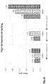
- the particle size distribution may be expressed in terms of d 10 , d 50 and d 90 , for example.
- the d 10 particle size is the particle size below which 10% by volume of the sample lies.
- the dso particle size is the particle size below which 50% by volume of the sample lies.
- the d 90 particle size is the particle size below which 90% by volume of the sample lies.
- the particle size measurements are volume-based particle size measurements, rather than number-based or mass-based particle size measurements.
- the spread of particle size may be expressed in terms of the span, which is defined as (d 90 -d 10 )/d 50 .
- the span is not more than 20, preferably not more than 10, preferably not more than 8, preferably not more than 4, preferably not more than 2, preferably not more than 1, or not more than 0.5.
- the particle size of the aerosol may be affected by the choice of the first or second (or further) position or operating condition by the user.
- the first position and second position may be associated with different air flows through the device.
- the first position may correspond to a configuration in which part of the air flow bypasses the vaporisation chamber
- the second position may correspond to a configuration in which a smaller or larger amount of the air flow bypasses the vaporisation chamber.
- the first and second positions may make other changes to the air flow.
- they may cause a structural change to the air flow path, for example lengthening it, introducing constrictions or broadenings into its cross section, altering the size or shape of the inlet or outlet and so on.
- the smoking substitute system comprises an air inlet, an outlet, and at least one air flow path between the air inlet and the outlet for conveying vaporized liquid aerosol precursor to the user
- the first operating condition and the second operating condition may have different air flow between the air inlet and the outlet.
- the first operating condition and the second operating condition may differ by the size of the air inlet.
- the first operating condition and the second operating condition may differ by the length, shape or cross-section of the air flow path.
- first position and second position can alter which inlet, which outlet, and/or which air flow path is active at a given time.
- the smoking substitute apparatus may comprise an air inlet and an outlet, and have a first air flow path between the air inlet and the outlet which is operable in the first configuration and a second air flow path between the air inlet and the outlet which is operable in the second configuration; or the smoking substitute apparatus may comprise multiple air inlets and an outlet, and have a first air flow path between a first air inlet and the outlet which is operable in the first configuration and a second air flow path between a second air inlet and the outlet which is operable in the second configuration.
- the first operating condition may correspond to an arrangement in which the main air flow is through a first air flow path between the air inlet and the outlet; and the second operating condition may correspond to an arrangement in which the main air flow is through a second air flow path between the air inlet and the outlet, the first and second air flow paths being different.
- the main body may comprise a first body air inlet and a second body air inlet
- the cartridge may comprise a cartridge air inlet and the outlet
- the smoking substitute system may comprise an air flow path through the cartridge air inlet and one of the body air inlets to the outlet; and in the first position the air flow path is through the first body air inlet and in the second position the air flow path is through the second body air inlet.
- the main body may comprise a body air inlet
- the cartridge may comprise a first cartridge air inlet, a second cartridge air inlet and the outlet
- the smoking substitute system may comprise an air flow path through one of the cartridge air inlets and the body air inlet to the outlet; and in the first position the air flow path is through the first cartridge air inlet and in the second position the air flow path is through the second cartridge air inlet.
- the smoking substitute apparatus (or main body engaged with the smoking substitute apparatus) may comprise a power source.
- the power source may be electrically connected (or connectable) to a heater of the smoking substitute apparatus (e.g. when the smoking substitute apparatus is engaged with the main body).
- the power source may be a battery (e.g. a rechargeable battery).
- a connector in the form of e.g. a USB port may be provided for recharging this battery.
- the power supplied by the power source may differ in the first and second operating conditions. For example, one may have a lower power than the other. This has knock on effects on the amount and properties of vapour produced. That is, the first operating condition and the second operating condition may differ by the amount of power supplied to the vaporizer.
- first and second operation conditions may route power to different parts of the smoking substitute system, for example to 'activate' or 'deactivate' reservoir(s).
- the first operating condition may correspond to an 'active' arrangement in which the vaporization of the liquid aerosol precursor by the vaporizer is possible; and the second operating condition may correspond to an 'inactive' arrangement in which the vaporization of the liquid aerosol precursor by the vaporizer is impossible. This enable a safety lock so the user can prevent accidental activation of the device.
- the smoking substitute apparatus When the smoking substitute apparatus is in the form of a consumable, the smoking substitute apparatus may comprise an electrical interface for interfacing with a corresponding electrical interface of the main body.
- One or both of the electrical interfaces may include one or more electrical contacts.
- the electrical interface of the main body when the main body is engaged with the consumable, the electrical interface of the main body may be configured to transfer electrical power from the power source to a heater of the consumable via the electrical interface of the consumable.
- Relative rotation of the main body and the cartridge may cause the electrical interface of the main body to engage with a different electrical interface of the consumable, or vice versa. That is, the main body and/or the consumable or cartridge may have multiple electrical interfaces, the first and second operating conditions corresponding to engagement between different pairs of these electrical interfaces.
- the electrical interface of the smoking substitute apparatus may also be used to identify the smoking substitute apparatus (in the form of a consumable) from a list of known types.
- the consumable may have a certain concentration of nicotine and the electrical interface may be used to identify this.
- the electrical interface may additionally or alternatively be used to identify when a consumable is connected to the main body.
- rotation of the main body and the cartridge as described herein can, for example, switch between preferred operating conditions for different types of consumable.
- the main body may comprise an identification means, which may, for example, be in the form of an RFID reader, a barcode or QR code reader.
- This identification means may be able to identify a characteristic (e.g. a type) of a consumable engaged with the main body.
- the consumable may include any one or more of an RFID chip, a barcode or QR code, or memory within which is an identifier and which can be interrogated via the identification means.
- the smoking substitute apparatus or main body may comprise a controller, which may include a microprocessor.
- the controller may be configured to control the supply of power from the power source to the heater of the smoking substitute apparatus (e.g. via the electrical contacts).
- a memory may be provided and may be operatively connected to the controller.
- the memory may include non-volatile memory.
- the memory may include instructions which, when implemented, cause the controller to perform certain tasks or steps of a method.
- the main body or smoking substitute apparatus may comprise a wireless interface, which may be configured to communicate wirelessly with another device, for example a mobile device, e.g. via Bluetooth®.
- the wireless interface could include a Bluetooth® antenna.
- Other wireless communication interfaces, e.g. WiFi®, are also possible.
- the wireless interface may also be configured to communicate wirelessly with a remote server.
- a puff sensor may be provided that is configured to detect a puff (i.e. inhalation from a user).
- the puff sensor may be operatively connected to the controller so as to be able to provide a signal to the controller that is indicative of a puff state (i.e. puffing or not puffing).
- the puff sensor may, for example, be in the form of a pressure sensor or an acoustic sensor. That is, the controller may control power supply to the heater of the consumable in response to a puff detection by the sensor. The control may be in the form of activation of the heater in response to a detected puff. That is, the smoking substitute apparatus may be configured to be activated when a puff is detected by the puff sensor.
- the puff sensor When the smoking substitute apparatus is in the form of a consumable, the puff sensor may be provided in the consumable or alternatively may be provided in the main body.
- flavourant is used to describe a compound or combination of compounds that provide flavour and/or aroma.
- the flavourant may be configured to interact with a sensory receptor of a user (such as an olfactory or taste receptor).
- the flavourant may include one or more volatile substances.
- the flavourant may be provided in solid or liquid form.
- the flavourant may be natural or synthetic.
- the flavourant may include menthol, liquorice, chocolate, fruit flavour (including e.g. citrus, cherry etc.), vanilla, spice (e.g. ginger, cinnamon) and tobacco flavour.
- the flavourant may be evenly dispersed or may be provided in isolated locations and/or varying concentrations.
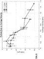
- Embodiments of the present invention therefore provide an aerosol with advantageous particle size characteristics across a range of flow rates of air through the apparatus. By altering the operating condition of the smoking substitute system, the properties of the aerosol may be correspondingly altered to the user's preference.
- the aerosol may have a Dv50 of at least 1.1 ⁇ m, at least 1.2 ⁇ m, at least 1.3 ⁇ m, at least 1.4 ⁇ m, at least 1.5 ⁇ m, at least 1.6 ⁇ m, at least 1.7 ⁇ m, at least 1.8 ⁇ m, at least 1.9 ⁇ m or at least 2.0 ⁇ m.
- the aerosol may have a Dv50 of not more than 4.9 ⁇ m, not more than 4.8 ⁇ m, not more than 4.7 ⁇ m, not more than 4.6 ⁇ m, not more than 4.5 ⁇ m, not more than 4.4 ⁇ m, not more than 4.3 ⁇ m, not more than 4.2 ⁇ m, not more than 4.1 ⁇ m, not more than 4.0 ⁇ m, not more than 3.9 ⁇ m, not more than 3.8 ⁇ m, not more than 3.7 ⁇ m, not more than 3.6 ⁇ m, not more than 3.5 ⁇ m, not more than 3.4 ⁇ m, not more than 3.3 ⁇ m, not more than 3.2 ⁇ m, not more than 3.1 ⁇ m or not more than 3.0 ⁇ m.
- a particularly preferred range for Dv50 of the aerosol is in the range 2-3 ⁇ m.
- the air inlet, flow passage, outlet and the vaporisation chamber may be configured so that, when the air flow rate inhaled by the user through the apparatus is 1.3 L min -1 , the average magnitude of velocity of air in the vaporisation chamber is in the range 0-1.3 ms -1 .
- the average magnitude velocity of air may be calculated based on knowledge of the geometry of the vaporisation chamber and the flow rate.
- the average magnitude of velocity of air in the vaporisation chamber may be at least 0.001 ms -1 , or at least 0.005 ms -1 , or at least 0.01 ms -1 , or at least 0.05 ms -1 .
- the average magnitude of velocity of air in the vaporisation chamber may be at most 1.2 ms -1 , at most 1.1 ms -1 , at most 1.0 ms -1 , at most 0.9 ms -1 , at most 0.8 ms -1 , at most 0.7 ms -1 or at most 0.6 ms -1 .
- the air inlet, flow passage, outlet and the vaporisation chamber may be configured so that, when the air flow rate inhaled by the user through the apparatus is 2.0 L min -1 , the average magnitude of velocity of air in the vaporisation chamber is in the range 0-1.3 ms -1 .
- the average magnitude velocity of air may be calculated based on knowledge of the geometry of the vaporisation chamber and the flow rate.
- the average magnitude of velocity of air in the vaporisation chamber may be at least 0.001 ms -1 , or at least 0.005 ms -1 , or at least 0.01 ms -1 , or at least 0.05 ms -1 .
- the average magnitude of velocity of air in the vaporisation chamber may be at most 1.2 ms -1 , at most 1.1 ms -1 , at most 1.0 ms -1 , at most 0.9 ms -1 , at most 0.8 ms -1 , at most 0.7 ms -1 or at most 0.6 ms -1 .
- the resultant aerosol particle size is advantageously controlled to be in a desirable range. It is further considered that the configuration of the apparatus can be selected so that the average magnitude of velocity of air in the vaporisation chamber can be brought within the ranges specified, at the exemplary flow rate of 1.3 L min -1 and/or the exemplary flow rate of 2.0 L min -1 .
- the vaporizer or aerosol generator may comprise a vaporiser element loaded with aerosol precursor, the vaporiser element being heatable by a heater and presenting a vaporiser element surface to air in the vaporisation chamber.
- a vaporiser element region may be defined as a volume extending outwardly from the vaporiser element surface to a distance of 1 mm from the vaporiser element surface.
- the operation of the aerosol generator or vaporizer may differ between the first and second operating conditions.
- the power supplied, circuits activated, or aerosol precursor loaded or vaporized may differ between the first and second operating conditions.
- the air inlet, flow passage, outlet and the vaporisation chamber may be configured so that, when the air flow rate inhaled by the user through the apparatus is 1.3 L min -1 , the average magnitude of velocity of air in the vaporiser element region is in the range 0-1.2 ms -1 .
- the average magnitude of velocity of air in the vaporiser element region may be calculated using computational fluid dynamics.
- the average magnitude of velocity of air in the vaporiser element region may differ between the first and second operating conditions.
- the average magnitude of velocity of air in the vaporiser element region may be at least 0.001 ms -1 , or at least 0.005 ms -1 , or at least 0.01 ms -1 , or at least 0.05 ms -1 .
- the average magnitude of velocity of air in the vaporiser element region may be at most 1.1 ms -1 , at most 1.0 ms -1 , at most 0.9 ms -1 , at most 0.8 ms -1 , at most 0.7 ms -1 or at most 0.6 ms -1 .
- the air inlet, flow passage, outlet and the vaporisation chamber may be configured so that, when the air flow rate inhaled by the user through the apparatus is 2.0 L min -1 , the average magnitude of velocity of air in the vaporiser element region is in the range 0-1.2 ms -1 .
- the average magnitude of velocity of air in the vaporiser element region may be calculated using computational fluid dynamics.
- the average magnitude of velocity of air in the vaporiser element region may be at least 0.001 ms -1 , or at least 0.005 ms -1 , or at least 0.01 ms -1 , or at least 0.05 ms -1 .
- the average magnitude of velocity of air in the vaporiser element region may be at most 1.1 ms -1 , at most 1.0 ms -1 , at most 0.9 ms -1 , at most 0.8 ms -1 , at most 0.7 ms -1 or at most 0.6 ms -1 .
- the resultant aerosol particle size is advantageously controlled to be in a desirable range. It is further considered that the velocity of air in the vaporiser element region is more relevant to the resultant particle size characteristics than consideration of the velocity in the vaporisation chamber as a whole. This is in view of the significant effect of the velocity of air in the vaporiser element region on the cooling of the vapour emitted from the vaporiser element surface.
- the air inlet, flow passage, outlet and the vaporisation chamber may be configured so that, when the air flow rate inhaled by the user through the apparatus is 1.3 L min -1 , the maximum magnitude of velocity of air in the vaporiser element region is in the range 0-2.0 ms -1 .
- the maximum magnitude of velocity of air in the vaporiser element region may differ between the first and second operating conditions.
- the maximum magnitude of velocity of air in the vaporiser element region may be at least 0.001 ms -1 , or at least 0.005 ms -1 , or at least 0.01 ms -1 , or at least 0.05 ms -1 .
- the maximum magnitude of velocity of air in the vaporiser element region may be at most 1.9 ms -1 , at most 1.8 ms -1 , at most 1.7 ms -1 , at most 1.6 ms -1 , at most 1.5 ms -1 , at most 1.4 ms -1 , at most 1.3 ms -1 or at most 1.2 ms -1 .
- the air inlet, flow passage, outlet and the vaporisation chamber may be configured so that, when the air flow rate inhaled by the user through the apparatus is 2.0 L min -1 , the maximum magnitude of velocity of air in the vaporiser element region is in the range 0-2.0 ms -1 .
- the maximum magnitude of velocity of air in the vaporiser element region may be at least 0.001 ms -1 , or at least 0.005 ms -1 , or at least 0.01 ms -1 , or at least 0.05 ms -1 .
- the maximum magnitude of velocity of air in the vaporiser element region may be at most 1.9 ms -1 , at most 1.8 ms -1 , at most 1.7 ms -1 , at most 1.6 ms -1 , at most 1.5 ms -1 , at most 1.4 ms -1 , at most 1.3 ms -1 or at most 1.2 ms -1 .
- the air inlet, flow passage, outlet and the vaporisation chamber may be configured so that, when the air flow rate inhaled by the user through the apparatus is 1.3 L min -1 , the turbulence intensity in the vaporiser element region is not more than 1%.
- the turbulence intensity in the vaporiser element region may differ between the first and second operating conditions.
- the turbulence intensity in the vaporiser element region may be not more than 0.95%, not more than 0.9%, not more than 0.85%, not more than 0.8%, not more than 0.75%, not more than 0.7%, not more than 0.65% or not more than 0.6%.
- the particle size characteristics of the generated aerosol may be determined by the cooling rate experienced by the vapour after emission from the vaporiser element (e.g. wick).
- the vaporiser element e.g. wick
- imposing a relatively slow cooling rate on the vapour has the effect of generating aerosols with a relatively large particle size.
- the parameters discussed above are considered to be mechanisms for implementing a particular cooling dynamic to the vapour.
- the air inlet, flow passage, outlet and the vaporisation chamber may be configured so that a desired cooling rate is imposed on the vapour.
- the particular cooling rate to be used depends of course on the nature of the aerosol precursor and other conditions. However, for a particular aerosol precursor it is possible to define a set of testing conditions in order to define the cooling rate, and by extension this imposes limitations on the configuration of the apparatus to permit such cooling rates as are shown to result in advantageous aerosols.
- the air inlet, flow passage, outlet and the vaporisation chamber may be configured so that the cooling rate of the vapour is such that the time taken to cool to 50 °C is not less than 16 ms, when tested according to the following protocol.
- the aerosol precursor is an e-liquid consisting of 1.6% freebase nicotine and the remainder a 65:35 propylene glycol and vegetable glycerine mixture, the e-liquid having a boiling point of 209 °C.
- Air is drawn into the air inlet at a temperature of 25 °C.
- the vaporiser is operated to release a vapour of total particulate mass 5 mg over a 3 second duration from the vaporiser element surface in an air flow rate between the air inlet and outlet of 1.3 L min -1 .
- the air inlet, flow passage, outlet and the vaporisation chamber may be configured so that the cooling rate of the vapour is such that the time taken to cool to 50 °C is not less than 16 ms, when tested according to the following protocol.
- the aerosol precursor is an e-liquid consisting of 1.6% freebase nicotine and the remainder a 65:35 propylene glycol and vegetable glycerine mixture, the e-liquid having a boiling point of 209 °C.
- Air is drawn into the air inlet at a temperature of 25 °C.
- the vaporiser is operated to release a vapour of total particulate mass 5 mg over a 3 second duration from the vaporiser element surface in an air flow rate between the air inlet and outlet of 2.0 L min -1 .
- the cooling rate of the vapour in particular the time taken to cool to 50 °C, may differ between the first and second operating conditions.
- Cooling of the vapour such that the time taken to cool to 50 °C is not less than 16 ms corresponds to an equivalent linear cooling rate of not more than 10 °C/ms.
- the equivalent linear cooling rate of the vapour to 50 °C may be not more than 9 °C/ms, not more than 8 °C/ms, not more than 7 °C/ms, not more than 6 °C/ms or not more than 5 °C/ms.
- Cooling of the vapour such that the time taken to cool to 50 °C is not less than 32 ms corresponds to an equivalent linear cooling rate of not more than 5 °C/ms.
- the testing protocol set out above considers the cooling of the vapour (and subsequent aerosol) to a temperature of 50 °C. This is a temperature which can be considered to be suitable for an aerosol to exit the apparatus for inhalation by a user without causing significant discomfort. It is also possible to consider cooling of the vapour (and subsequent aerosol) to a temperature of 75 °C. Although this temperature is possibly too high for comfortable inhalation, it is considered that the particle size characteristics of the aerosol are substantially settled by the time the aerosol cools to this temperature (and they may be settled at still higher temperature).
- the air inlet, flow passage, outlet and the vaporisation chamber may be configured so that the cooling rate of the vapour is such that the time taken to cool to 75 °C is not less than 4.5 ms, when tested according to the following protocol.
- the aerosol precursor is an e-liquid consisting of 1.6% freebase nicotine and the remainder a 65:35 propylene glycol and vegetable glycerine mixture, the e-liquid having a boiling point of 209 °C.
- Air is drawn into the air inlet at a temperature of 25 °C.
- the vaporiser is operated to release a vapour of total particulate mass 5 mg over a 3 second duration from the vaporiser element surface in an air flow rate between the air inlet and outlet of 1.3 L min -1 .
- the air inlet, flow passage, outlet and the vaporisation chamber may be configured so that the cooling rate of the vapour is such that the time taken to cool to 75 °C is not less than 4.5 ms, when tested according to the following protocol.
- the aerosol precursor is an e-liquid consisting of 1.6% freebase nicotine and the remainder a 65:35 propylene glycol and vegetable glycerine mixture, the e-liquid having a boiling point of 209 °C.
- Air is drawn into the air inlet at a temperature of 25 °C.
- the vaporiser is operated to release a vapour of total particulate mass 5 mg over a 3 second duration from the vaporiser element surface in an air flow rate between the air inlet and outlet of 2.0 L min -1 .
- the cooling rate of the vapour in particular the time taken to cool to 75 °C, may differ between the first and second operating conditions.
- the equivalent linear cooling rate of the vapour to 75 °C may be not more than 29 °C/ms, not more than 28 °C/ms, not more than 27 °C/ms, not more than 26 °C/ms, not more than 25 °C/ms, not more than 24 °C/ms, not more than 23 °C/ms, not more than 22 °C/ms, not more than 21 °C/ms, not more than 20 °C/ms, not more than 19 °C/ms, not more than 18 °C/ms, not more than 17 °C/ms, not more than 16 °C/ms, not more than 15 °C/ms, not more than 14 °C/ms, not more than 13 °C/ms, not more than 12 °C/ms, not more than 11 °C/ms or not more than 10 °C/ms.
- Cooling of the vapour such that the time taken to cool to 75 °C is not less than 13 ms corresponds to an equivalent linear cooling rate of not more than 10 °C/ms.
- the invention includes the combination of the aspects and preferred features described except where such a combination is clearly impermissible or expressly avoided.
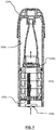
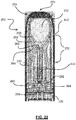
- FIGS 17 and 18 illustrate a smoking substitute system in the form of an e-cigarette system 110.
- the system 110 comprises a main body 120 of the system 110, and a smoking substitute apparatus in the form of an e-cigarette consumable (or "pod") 150.
- the consumable 150 (sometimes referred to herein as a smoking substitute apparatus) is removable from the main body 120, so as to be a replaceable component of the system 110.
- the e-cigarette system 110 is a closed system in the sense that it is not intended that the consumable should be refillable with e-liquid by a user.
- the main body and cartridge (smoking substitute apparatus, or 'consumable' herein) are rotatably engagable.
- the mechanism for this is not visible in Figures 17 and 18 .
- the consumable 150 is configured to engage the main body 120.
- Figure 17 shows the main body 120 and the consumable 150 in an engaged state
- Figure 18 shows the main body 120 and the consumable 150 in a disengaged state.
- a portion of the consumable 150 is received in a cavity of corresponding shape in the main body 120 and is retained in the engaged position by way of a snap-engagement mechanism.
- the main body 120 and consumable 150 may be engaged by screwing one into (or onto) the other, or through a bayonet fitting, or by way of an interference fit.
- One or both of them may be fitted with one or more magnet and/or areas of magnetic material, for example on the surface(s) intended to come into contact with the other part, to magnetically engage the main body 120 and the consumable 150.
- the system 110 is configured to vaporise an aerosol precursor, which in the illustrated reference arrangement is in the form of a nicotine-based e-liquid 160.
- the e-liquid 160 comprises nicotine and a base liquid including propylene glycol and/or vegetable glycerine.
- the e-liquid 160 is flavoured by a flavourant.
- the e-liquid 160 may be flavourless and thus may not include any added flavourant.
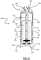
- FIG 19 shows a schematic longitudinal cross sectional view of a reference arrangement of the smoking substitute apparatus forming part of the smoking substitute system shown in Figures 17 and 18 .
- the e-liquid 160 is stored within a reservoir in the form of a tank 152 that forms part of the consumable 150.
- the consumable 150 is a "single-use" consumable 150. That is, upon exhausting the e-liquid 160 in the tank 152, the intention is that the user disposes of the entire consumable 150.
- the term "single-use" does not necessarily mean the consumable is designed to be disposed of after a single smoking session.
- the tank may include a vent (not shown) to allow ingress of air to replace e-liquid that has been used from the tank.
- the consumable 150 preferably includes a window 158 (see Figures 17 and 18 ), so that the amount of e-liquid in the tank 152 can be visually assessed.
- the main body 120 includes a slot 157 so that the window 158 of the consumable 150 can be seen whilst the rest of the tank 152 is obscured from view when the consumable 150 is received in the cavity of the main body 120.
- the consumable 150 may be referred to as a "clearomizer” when it includes a window 158, or a "cartomizer” when it does not.
- the e-liquid i.e. aerosol precursor
- the tank may be refillable with e-liquid or the e-liquid may be stored in a non-consumable component of the system.
- the e-liquid may be stored in a tank located in the main body or stored in another component that is itself not single-use (e.g. a refillable cartomizer).
- the external wall of tank 152 is provided by a casing of the consumable 150.
- the tank 152 annularly surrounds, and thus defines a portion of, a passage 170 that extends between a vaporiser inlet 172 and an outlet 174 at opposing ends of the consumable 150.
- the passage 170 comprises an upstream end at the end of the consumable 150 that engages with the main body 120, and a downstream end at an opposing end of the consumable 150 that comprises a mouthpiece 154 of the system 110.
- a plurality of device air inlets 176 are formed at the boundary between the casing of the consumable and the casing of the main body.
- the device air inlets 176 are in fluid communication with the vaporiser inlet 172 through an inlet flow channel 178 formed in the cavity of the main body which is of corresponding shape to receive a part of the consumable 150. Air from outside of the system 110 can therefore be drawn into the passage 170 through the device air inlets 176 and the inlet flow channels 178.
- the passage 170 may be partially defined by a tube (e.g. a metal tube) extending through the consumable 150.
- the passage 170 is shown with a substantially circular cross-sectional profile with a constant diameter along its length.
- the passage may have other cross-sectional profiles, such as oval shaped or polygonal shaped profiles.
- the cross sectional profile and the diameter (or hydraulic diameter) of the passage may vary along its longitudinal axis.
- the smoking substitute system 110 is configured to vaporise the e-liquid 160 for inhalation by a user.
- the consumable 150 comprises a heater having a porous wick 162 and a resistive heating element in the form of a heating filament 164 that is helically wound (in the form of a coil) around a portion of the porous wick 162.
- the porous wick 162 extends across the passage 170 (i.e. transverse to a longitudinal axis of the passage 170 and thus also transverse to the air flow along the passage 170 during use) and opposing ends of the wick 162 extend into the tank 152 (so as to be immersed in the e-liquid 160). In this way, e-liquid 160 contained in the tank 152 is conveyed from the opposing ends of the porous wick 162 to a central portion of the porous wick 162 so as to be exposed to the airflow in the passage 170.
- the helical filament 164 is wound about the exposed central portion of the porous wick 162 and is electrically connected to an electrical interface in the form of electrical contacts 156 mounted at the end of the consumable that is proximate the main body 120 (when the consumable and the main body are engaged).
- electrical contacts 156 make contact with corresponding electrical contacts (not shown) of the main body 120.
- the main body electrical contacts are electrically connectable to a power source (not shown) of the main body 120, such that (in the engaged position) the filament 164 is electrically connectable to the power source. In this way, power can be supplied by the main body 120 to the filament 164 in order to heat the filament 164.
- the filament 164 and the exposed central portion of the porous wick 162 are positioned across the passage 170. More specifically, the part of passage that contains the filament 164 and the exposed portion of the porous wick 162 forms a vaporisation chamber.
- the vaporisation chamber has the same cross-sectional diameter as the passage 170. However, in some embodiments the vaporisation chamber may have a different cross sectional profile compared with the passage 170. For example, the vaporisation chamber may have a larger cross sectional diameter than at least some of the downstream part of the passage 170 so as to enable a longer residence time for the air inside the vaporisation chamber.
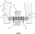
- FIG 20 illustrates in more detail the vaporisation chamber and therefore the region of the consumable 150 around the wick 162 and filament 164.
- the helical filament 164 is wound around a central portion of the porous wick 162.
- the porous wick extends across passage 170.
- E-liquid 160 contained within the tank 152 is conveyed as illustrated schematically by arrows 401, i.e. from the tank and towards the central portion of the porous wick 162.
- porous wick 162 When the user inhales, air is drawn from through the inlets 176 shown in Figure 19 , along inlet flow channel 178 to vaporisation chamber inlet 172 and into the vaporisation chamber containing porous wick 162.
- the porous wick 162 extends substantially transverse to the airflow direction.
- the airflow passes around the porous wick, at least a portion of the airflow substantially following the surface of the porous wick 162.
- the airflow may follow a curved path around an outer periphery of the porous wick 162.
- the filament 164 is heated so as to vaporise the e-liquid which has been wicked into the porous wick.
- the airflow passing around the porous wick 162 picks up this vaporised e-liquid, and the vapour-containing airflow is drawn in direction 403 further down passage 170.
- the power source of the main body 120 may be in the form of a battery (e.g. a rechargeable battery such as a lithium ion battery).
- the main body 120 may comprise a connector in the form of e.g. a USB port for recharging this battery.
- the main body 120 may also comprise a controller that controls the supply of power from the power source to the main body electrical contacts (and thus to the filament 164). That is, the controller may be configured to control a voltage applied across the main body electrical contacts, and thus the voltage applied across the filament 164. In this way, the filament 164 may only be heated under certain conditions (e.g. during a puff and/or only when the system is in an active state).
- the main body 120 may include a puff sensor (not shown) that is configured to detect a puff (i.e. inhalation).
- the puff sensor may be operatively connected to the controller so as to be able to provide a signal, to the controller, which is indicative of a puff state (i.e. puffing or not puffing).
- the puff sensor may, for example, be in the form of a pressure sensor or an acoustic sensor.
- the main body 120 and consumable 150 may comprise a further interface which may, for example, be in the form of an RFID reader, a barcode or QR code reader.
- This interface may be able to identify a characteristic (e.g. a type) of a consumable 150 engaged with the main body 120.
- the consumable 150 may include any one or more of an RFID chip, a barcode or QR code, or memory within which is an identifier and which can be interrogated via the interface.
- An apparatus may be configured such that in use, at least part of the air flow drawn by a user through the apparatus from the air inlet to the outlet bypasses the vaporisation chamber defined by the enclosure.
- it may be configured so that when the main body 120 and the consumable 150 are in a certain rotational relationship, a first position, at least part of the air flow drawn by a user through the apparatus from the air inlet to the outlet bypasses the vaporisation chamber defined by the enclosure; and in a different rotational relationship, a second position, none of the air flow drawn by a user through the apparatus from the air inlet to the outlet bypasses the vaporisation chamber defined by the enclosure.
- Figure 21 illustrates a schematic longitudinal cross sectional view of a second reference arrangement of the smoking substitute apparatus forming part of the smoking substitute system shown in Figures 17 and 18 .
- the arrangement illustrated in Figure 21 differs from the first reference arrangement illustrated in Figure 19 in that the substitute smoking apparatus includes two bypass passages 180 in addition to the vaporiser passage 170.
- the bypass air passages extend between the plurality of device air inlets 176 and two outlets 184.
- the number of bypass passages 180 and corresponding outlets 184 may be greater or smaller than in the illustrated example.
- the bypass passage 180 is shown with a substantially circular cross-sectional profile with a constant diameter along its length.
- the bypass passage 180 may have other cross-sectional profiles, such as oval shaped or polygonal shaped profiles.
- the cross sectional profile and the diameter (or hydraulic diameter) of the bypass passage 180 may vary along its longitudinal axis.
- a bypass passage 180 means that a part of the air drawn through the smoking substitute apparatus 150a when a user inhales via the mouthpiece 154 is not drawn through the vaporisation chamber. This has the effect of reducing the flow rate through the vaporisation chamber in correspondence with the respective flow resistances presented by the vaporiser passage 170 and the bypass passage 180. This can reduce the correlation between the flow rate through the smoking substitute apparatus 150a (i.e. the user's draw rate) and the particle size generated when the e-liquid 160 is vaporised and subsequently forms an aerosol. Therefore, the smoking substitute apparatus 150a of the second reference arrangement can deliver a more consistent aerosol to a user.
- the user may be able to control the extent to which the bypass passage 180 is open, by rotation of the main body 120 with respect to the consumable 150.
- Various ways to accomplish this, such as partial blocking of the bypass passage 180, can be envisaged.
- the smoking substitute apparatus 150a of the second reference arrangement is capable of producing an increased particle droplet size, dso, based on typical inhalation rates undertaken by a user, compared to the first reference arrangement of Figure 19 .
- Such larger droplet sizes may be beneficial for the delivery of vapour to a user's lungs.
- the preferred ratio between the dimensions of the bypass passage 180 and the dimensions of the vaporiser passage 170, and hence flow rate in the respective passages may be determined from representative user inhalation rates and from the required air flow rate through the vaporisation chamber to deliver a desired droplet size.
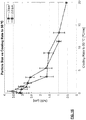
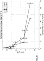
- an average total flow rate of 1.3 litres per minute may be split such that 0.8 litres per minute passes through the bypass air channel 180, and 0.5 litres per minute passes through the vaporiser channel 170, a bypass:vaporiser flow rate ratio of 1.6:1.
- a flow rate may provide an average droplet size, dso, of 1-3 ⁇ m (more preferably 2-3 ⁇ m) with a span of not more than 20 (preferably not more than 10).
- Alternative flow rate ratios may be provided based on calculations and measurements of user flow rate, vaporiser flow rate, and average droplet size dso.
- a bypass:vaporiser flow rate ratio of between 0.5:1 and 20:1, typically at an average total flow rate of 1.3 litres per minute may be advantageous depending on the configuration of the smoking substitute apparatus.
- the bypass passage and vaporiser passage extend from a common device inlet 176. This has the benefit of ensuring more consistent airflow through the bypass passage 180 and vaporiser passage 170 across the lifetime of the smoking substitute apparatus 150a, since any obstruction that impinges on an air inlet 176 will affect the airflow through both passages equally. The impact of inlet manufacturing variations can also be reduced for the same reason. This can therefore improve the user experience for the smoking substitute apparatus 150a. Furthermore, the provision of a common device inlet 176 simplifies the construction and external appearance of the device.
- bypass passage 180 and vaporiser passage 170 separate upstream of the vaporisation chamber. Therefore, no vapour is drawn through the bypass passage 180. Furthermore, because the bypass passage leads to outlet 184 that is separate from outlet 174 of the vaporiser passage, substantially no mixing of the bypass air and vaporiser air occurs within the smoking substitute apparatus 150a. Such mixing could otherwise lead to excessive cooling of the vapour and hence a build-up of condensation within the smoking substitute apparatus 150a. Such condensation could have adverse implications for delivering vapour to the user, for example by causing the user to draw liquid droplets rather than vapour when "puffing" on the mouthpiece 154.
- the apparatus may include one or a combination of features of a third reference arrangement (and variations thereof), shown schematically in Figure 22 , where such features are combinable with the present invention.
- This third reference arrangement is described below.
- Figure 22 illustrates a longitudinal cross sectional view of a consumable 250 according to a further arrangement.
- the consumable 250 is shown attached, at a first end of the consumable 250, to the main body 120 of Figure 17 and Figure 18 . More specifically, the consumable 250 is configured to engage and disengage with the main body 120 and is interchangeable with the first reference arrangement 150 as shown in Figures 19 and 20 . Furthermore, the consumable 250 is configured to interact with the main body 120 in the same manner as the first reference arrangement 150 and the user may operate the consumable 250 in the same manner as the first reference arrangement 150.
- the consumable 250 comprises a housing.
- the consumable 250 comprises an aerosol generation chamber 280 in the housing.
- the aerosol generation chamber 280 takes the form of an open ended container, or a cup, with a single chamber outlet 282 opened towards the outlet 274 of the consumable 250.
- the housing has a plurality of air inlets 272 defined or opened at the sidewall of the housing.
- An outlet 274 is defined or opened at a second end of the consumable 250 that comprises a mouthpiece 254.
- a pair of passages 270 each extend between the respective air inlets 272 and the outlet 274 to provide flow passage for an air flow 412 as a user puffs on the mouthpiece 254.
- the chamber outlet 282 is configured to be in fluid communication with the passages 270.
- the passages 270 extend from the air inlets 272 towards the first end of the consumable 250 before routing back to towards the outlet 274 at the second end of the consumable 250. That is, a portion of each of the passages 270 axially extends alongside the aerosol generation chamber 280.
- the passages 270 may extend from the air inlet 272 directly to the outlet 274 without routing towards the first end of consumable 250, e.g. the passages 270 may not axially extend alongside the aerosol generation chamber 280.
- the first and second positions, or further positions may correspond to positions in which so selection of the air lets 272 are open or closed, to modify air flow through the passages.
- the housing may not be provided with any air inlet for an air flow to enter the housing.
- the chamber outlet may be directly connected to the outlet of the housing by an aerosol passage and therefore said aerosol passage may only convey aerosol as generated in the aerosol generation chamber.
- the discharge of aerosol may be driven at least in part by the pressure increase during vaporisation of aerosol form.
- the chamber outlet 282 is positioned downstream from the heater in the direction of the vapour and/or aerosol flow 414 and serves as the only gas flow passage to the internal volume of the aerosol generation chamber 280.
- the aerosol generation chamber 280 is sealed against air flow except for having the chamber outlet 282 in communication with the passages 270, the chamber outlet 282 permitting, in use, aerosol generated by the heater to be entrained into an air flow along the passage 270.
- the sealed aerosol generation chamber 280 may comprise a plurality of chamber outlets 282 each arranged in fluid commutation with the passages 270.
- the aerosol generation chamber 280 does not comprise any aperture upstream of the heater that may serve as an air flow inlet (although in some arrangements a vent may be provided).
- the passages 270 of the consumable 250 allow the air flow, e.g. an entire amount of air flow, entering the housing to bypass the aerosol generation chamber 280.
- the aerosol generation chamber may be considered to be a "stagnant" chamber.
- the volumetric flowrate of vapour and/or aerosol in the aerosol generation chamber is configured to be less than 0.1 litre per minute.
- the vaporised aerosol precursor may cool and therefore condense to form an aerosol in the aerosol generation chamber 280, which is subsequently expulsed into or entrained with the air flow in passages 270.
- a portion of the vaporised aerosol precursor may remain as a vapour before leaving the aerosol generation chamber 280, and subsequently forms an aerosol as it is cooled by the air flow in the passages 270.
- the flow path of the vapour and/or aerosol 414 is illustrated in Figure 22 .
- the chamber outlet 282 is configured to be in fluid communication with a junction 290 at each of the passages 270 through a respective vapour channel 292.
- the junctions 290 merge the vapour channels 292 with their respective passages 270 such that vapour and/or aerosol formed in the aerosol generation chamber 280 may expand or entrain into the passages 270 through junction inlets of said junctions 290.
- the vapour channels form a buffering volume to minimise the amount of air flow that may back flow into the aerosol generation chamber 280.
- the chamber outlet 282 may directly open towards the junction 290 at the passage, and therefore in such variations the vapour channel 292 may be omitted.
- the chamber outlet may be closed by a one way valve.
- Said one way valve may be configured to allow a one way flow passage for the vapour and/or aerosol to be discharged from the aerosol generation chamber, and to reduce or prevent the air flow in the passages from entering the aerosol generation chamber.
- the aerosol generation chamber 280 is configured to have a length of 20mm and a volume of 680mm 3 .
- the aerosol generation chamber is configured to allow vapour to be expulsed through the chamber outlet at a rate greater than 0.1mg/second.
- the aerosol generation chamber may be configured to have an internal volume ranging between 68mm 3 to 680mm 3 , wherein the length of the aerosol generation chamber may range between 2mm to 20mm.
- each of the passages 270 axially extends alongside the aerosol generation chamber 280.
- the passages 270 are formed between the aerosol generation chamber 280 and the housing. Such an arrangement reduces heat transfer from the aerosol generation chamber 280 to the external surfaces of the housing.
- the aerosol generation chamber 280 comprises a heater extending across its width.
- the heater comprises a porous wick 262 and a heating filament 264 helically wound around a portion of the porous wick 162.
- a tank 252 is provided in the space between the aerosol generation chamber 280 and the outlet 274, the tank being for storing a reservoir of aerosol precursor. Therefore in contrast with the reference arrangement as shown in Figures 19 and 20 , the tank 252 in the third reference arrangement does not substantially surround the aerosol generation chamber nor the passage 270. Instead, as shown in Figure 22 , the tank is substantially positioned above the aerosol generation chamber 280 and the porous wick 262 when the consumable 250 is placed in an upright orientation during use.
- the end portions of the porous wick 262 each extend through the sidewalls of the aerosol generation chamber 280 and into a respective liquid conduit 266 which is in fluid communication with the tank 252.
- the wick 262, saturated with aerosol precursor, may prevent gas flow passage into the liquid conduits 266 and the tank 252.
- Such an arrangement may allow the aerosol precursor stored in the tank 252 to convey towards the porous wick 262 through the liquid conduits 266 by gravity.
- the liquid conduits 266 are configured to have a hydraulic diameter that allow a controlled amount of aerosol precursor to flow from the tank 252 towards the porous wick 262. More specifically, the size of liquid conduits 266 are selected based on the rate of aerosol precursor consumption during vaporisation.
- the liquid conduits 266 are sized to allow a sufficient amount of aerosol precursor to flow towards and replenish the wick, yet not so large as to cause excessive aerosol precursor to leak into the aerosol generation chamber.
- the liquid conduits 266 are configured to have a hydraulic diameter ranging from 0.01mm to 10mm or 0.01 mm to 5mm.
- the liquid conduits 266 are configured to have a hydraulic diameter in the range of 0.1mm to 1mm.
- the heating filament is electrically connected to electrical contacts 256 at the base of the aerosol generation chamber 280, sealed to prevent air ingress or fluid leakage. As shown in Figure 22 , when the first end of the consumable 250 is received into the main body 120, the electrical contacts 256 establish electrical communication with corresponding electrical contacts of the main body 120, and thereby allow the heater to be energised.
- the consumable there may be multiple possible electrical contacts provided on the consumable and/or the main body.
- This can enable the user to alter, for example, the power supplied to the heater.
- it may enable the user to switch between or otherwise alter the balance between vapour from each reservoir.
- the consumable there may be a first circuit attached to a heater for a first reservoir and a second circuit attached to a heater for a second reservoir.
- the electrical contacts in the main body connect to the first circuit, enabling aerosol precursor liquid in the first reservoir to be vaporized.
- the electrical contacts in the main body connect to the second circuit, enabling aerosol precursor liquid in the second reservoir to be vaporized.
- the vaporised aerosol precursor, or aerosol in the condensed form may discharge from the aerosol generation chamber 280 based on pressure difference between the aerosol generation chamber 280 and the passages 270.
- pressure difference may arise form i) an increased pressure in the aerosol generation chamber 280 during vaporisation of aerosol form, and/or ii) a reduced pressure in the passage during a puff.
- the heater when the heater is energised and forms a vapour, it expands in to the stagnant cavity of the aerosol generation chamber 280 and thereby causes an increase in internal pressure therein.
- the vaporised aerosol precursor may immediately begin to cool and may form aerosol droplets.
- Such increase in internal pressure causes convection inside the aerosol generation chamber which aids expulsing aerosol through the chamber outlet 282 and into the passages 270.
- the heater is positioned within the stagnant cavity of the aerosol generation chamber 280, e.g. the heater is spaced from the chamber outlet 282.
- Such arrangement may reduce or prevent the amount of air flow entering the aerosol generation chamber, and therefore it may minimise the amount of turbulence in the vicinity of the heater.
- such arrangement may increase the residence time of vapour in the stagnant aerosol generation chamber 280, and thereby may result in the formation of larger aerosol droplets.
- the heater may be positioned adjacent to the chamber outlet and therefore that the path of vapour 414 from the heater to the chamber outlet 282 is shortened. This may allow vapour to be drawn into or entrained with the air flow in a more efficient manner.
- the junction inlet at each of the junctions 290 opens in a direction orthogonal or non-parallel to the air flow. That is, the junction inlet each opens at a sidewall of the respective passages 270.
- the aerosol may be fully formed in the air flow and be drawn out through the outlet at the mouthpiece.
- the aerosol as generated by the illustrated third reference arrangement has a median droplet size dso of at least 1 ⁇ m. More preferably, the aerosol as generated by the illustrated third reference arrangement has a median droplet size dso of ranged between 2 ⁇ m to 3 ⁇ m.
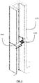
- Figures 23-27 are provided to show embodiments of the interface between the main body and the consumable or cartridge. This illustrate how the rotation f the two with respect to one another may operate to provide multiple positions each associated with a particular operating condition of the smoking substitute system.
- Figure 23 shows a main body 120 having a trunk portion 220 and an outer interface portion 230.
- the trunk portion 220 is illustrated as having a tubular shape, with an approximately circular cross section, but it will of course be appreciated that these shapes can be freely varied.
- the outer interface portion 230 is a tubular projection from a contact surface 221, the contact surface 221 forming a flat annular surface surrounding the outer interface portion 230.
- the outer interface portion 230 has an outer interface face 231 at its end.
- the outer interface portion 230 is illustrated as having a circular cross section but again other shapes can be envisages.
- an inner interface portion 232 which here is provided as a column again projecting from the contact surface 221 of the trunk portion 220.
- the inner interface portion 232 is tipped with an inner interface face 233.
- the inner interface portion 232 and the inner interface face 233 are not visible in Figure 23 .
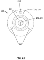
- Figure 24 shows the main body 120 of Figure 23 from 'above'.
- annular contact surface 221 from which the outer interface portion 230 tipped with the outer interface face 231 projects.
- the contact surface 221 is visible within it.
- columnar inner interface portion 232 tipped with the inner interface face 233.
- the outer and inner interface faces 231, 233 are provided with electrical contacts. These contacts may be supplied with power from a source within the main body 120. When a consumable or cartridge is loaded, as explained below, these contacts connect with corresponding contacts in the cartridge to supply power to it and hence generate vapour.
- main body magnets 240 can engage with corresponding sections on the consumable discussed below to attach the consumable to the main body 120. It will be recognised that if magnets are present on the main body 120, magnetic material can be present on the consumable instead of magnets. Similarly, the main body magnets 240 can be replaced with magnetic material if one or more magnets are present on the consumable.
- the consumable 150 is illustrated in Figure 25 . It includes an annular contact surface 250 sized to engage with the contact surface 221 of the main body 120.
- the annular contact surface 250 of the consumable 150 surrounds an interface cavity 260 shaped to receive the outer interface portion 230.
- On the inner surface 261 of the cavity are provided electrical contacts.
- the inner electrical contact 262 is positioned centrally, such that it touches the electrical contact of the inner interface face 233 when the main body 120 and consumable 150 are attached.
- the outer electrical contact 263 is positioned at the outer edge of the cavity 260, such that it touches the electrical contact of the outer interface face 231 when the main body 120 and consumable 150 are attached.
- consumable or cartridge magnets 270 are arranged on the annular contact surface 250. They are evenly spaced although clearly this is not essential. These magnets can engage with corresponding sections on the main body discussed above to attach the consumable 150 to the main body 120. It will be recognised that if magnets are present on the main body 120, magnetic material can be present on the consumable instead of magnets 270. Similarly, the main body magnets 240 can be replaced with magnetic material if one or more magnets 270 are present on the consumable 150.
- shape of the outer interface portion 230 of the main body 120 and the interface cavity 260 of the consumable 150 allow the rotatable engagement of the main body 120 and the consumable 150.
- magnetic coupling between the parts 240 on the main body and 270 on the consumable holds them in position.
- the magnetic link can be broken by the user with torsion on the main body 120 and/or consumable 150, and relative rotation leads to a different magnetic interaction forming and thus holding the main body 120 and consumable 150 in a different relative rotation to when they began. This is equivalent to a movement from a first position to a second position as defined herein.
- a cavity/projection interface is preferable as it can allow free turning or spinning of the consumable and main body with respect to one another.
- The is particularly the case where a circular cross section is chosen for the projection and the corresponding cavity.
- the user may benefit from an uninterrupted operation of the smoking substitute system, while transitioning from a first operating condition to a second operating condition.
- the main body 120 may comprise a series of corresponding convex and concave portions, which correspond only in certain rotational alignments, to define first, second and further positions.
- the main body may have the concave portions, or the convex portions, or a mixture of both. The corresponding portions are provided on the consumable.
- Those portions could, for example, be in the positions shown for magnetic parts 240 and 270 in Figures 24-26 .
- the annular contact faces 221 and 250 could be magnetic to provide a force to hold the main body 120 and the consumable 150 together.
- Figure 26 shows the smoking substitute system with the main body 120 and the consumable cartridge 150 engaged.
- the fit between the outer interface portion 230 and the cavity 260 can be seen, along with the engagement between inner interface face 233 and inner electrical contact 262, and between outer interface face 231 and outer electrical contact 263.
- Relative rotation of the main body 120 and the consumable 150 moves the relative positions of the engagement magnetic parts 240, 270 to different configurations. It moves the position of the inner and outer electrical contacts 262, 263 on the surface of the inner interface face 233 and outer interface face 231. This alters the operation condition of the smoking substitute system. For example the position of the outer electrical contact 263 on the surface of the outer interface face 263 may alter the resistance in the power circuit, and thereby lead to a different power being supplied to the consumable in different rotational positions.
- FIG. 27 A further example is illustrated in Figure 27 .
- the outer wall of the consumable 150 is provided with an air inlet hole 280 (see Figure 27(a), (e), (f) ).
- the outer wall of the outer interface portion 230 of the main body 120 is provided with a series of through holes 290 of different sizes (here, three: see Figure 27(b), (c), (d) ). Those through holes lead to the space between the outer interface portion 230 and the inner interface portion 232. That space can form part of the air passage to the outlet for vapour inhalation by the user.
- the air inlet hole 280 can be aligned with different ones of the through holes 290. This has the effect of increasing or decreasing the effective size of the inlet into the device, altering the amount and properties of air flow with the effects described herein.
- the three positions aligning the air inlet hole with one of the three through holes 290 therefore cause the smoking substitute system to operate in three different operating conditions.
- Aerosol droplet size is a considered to be an important characteristic for smoking substitution devices. Droplets in the range of 2-5 ⁇ m are preferred in order to achieve improved nicotine delivery efficiency and to minimise the hazard of second-hand smoking. However, at the time of writing (September 2019), commercial EVP devices typically deliver aerosols with droplet size averaged around 0.5 ⁇ m, and to the knowledge of the inventors not a single commercially available device can deliver an aerosol with an average particle size exceeding 1 ⁇ m.
- the present inventors speculate, without themselves wishing to be bound by theory, that there has to date been a lack of understanding in the mechanisms of e-liquid evaporation, nucleation and droplet growth in the context of aerosol generation in smoking substitute devices. The present inventors have therefore studied these issues in order to provide insight into mechanisms for the generation of aerosols with larger particles. The present inventors have carried out experimental and modelling work alongside theoretical investigations, leading to significant achievements as now reported.
- This disclosure considers the roles of air velocity, air turbulence and vapour cooling rate in affecting aerosol particle size.
- a Malvern PANalytical Spraytec laser diffraction system was employed for the particle size measurement.
- the same coil and wick 1.5 ohms Ni-Cr coil, 1.8 mm Y07 cotton wick
- Y07 represents the grade of cotton wick, meaning that the cotton has a linear density of 0.7 grams per meter.
- Particle sizes were measured in accordance with ISO 13320:2009(E), which is an international standard on laser diffraction methods for particle size analysis. This is particularly well suited to aerosols, because there is an assumption in this standard that the particles are spherical (which is a good assumption for liquid-based aerosols). The standard is stated to be suitable for particle sizes in the range 0.1 micron to 3 mm.
- Figure 2 shows a schematic perspective longitudinal cross sectional view of an example rectangular tube 1170 with a wick 1162 and heater coil 1164 installed.
- the location of the wick is about half way along the length of the tube. This is intended to allow the flow of air along the tube to settle before reaching the wick.
- Figure 3 shows a schematic transverse cross sectional view an example rectangular tube 1170 with a wick 1162 and heater coil 1164 installed.
- the internal width of the tube is 12 mm
- the rectangular tubes were manufactured to have same internal depth of 6 mm in order to accommodate the standardized coil and wick, however the tube internal width varied from 4.5 mm to 50 mm.
- the "tube size" is referred to as the internal width of rectangular tubes.
- the rectangular tubes with different dimensions were used to generate aerosols that were tested for particle size in a Malvern PANalytical Spraytec laser diffraction system.
- An external digital power supply was dialled to 2.6A constant current to supply 10W power to the heater coil in all experiments. Between two runs, the wick was saturated manually by applying one drop of e-liquid on each side of the wick.
- Table 1 shows a list of experiments in this study.
- the values in "calculated air velocity” column were obtained by simply dividing the flow rate by the intersection area at the centre plane of wick.
- Turbulence intensity was introduced as a quantitative parameter to assess the level of turbulence. The definition and simulation of turbulence intensity is discussed below (see section 3.2).
- Figures 4A-4D show air flow streamlines in the four devices used in this turbulence study.
- Figure 4A is a standard 12mm rectangular tube with wick and coil installed as explained in the previous section, with no jetting panel.
- Figure 4B has a jetting panel located 10mm below (upstream from) the wick.
- Figure 4C has the same jetting panel 5mm below the wick.
- Figure 4D has the same jetting panel 2.5mm below the wick.
- the jetting panel has an arrangement of apertures shaped and directed in order to promote jetting from the downstream face of the panel and therefore to promote turbulent flow.
- the jetting panel can introduce turbulence downstream, and the panel causes higher level of turbulence near the wick when it is positioned closer to the wick.
- the four geometries gave turbulence intensities of 0.55%, 0.77%, 1.06% and 1.34%, respectively, with Figure 4A being the least turbulent, and Figure 4D being the most turbulent.
- the experimental set up is shown in Figure 5 .
- the testing used a Carbolite Gero EHA 12300B tube furnace 3210 with a quartz tube 3220 to heat up the air. Hot air in the tube furnace was then led into a transparent housing 3158 that contains the EVP device 3150 to be tested.
- a thermocouple meter 3410 was used to assess the temperature of the air pulled into the EVP device. Once the EVP device was activated, the aerosol was pulled into the Spraytec laser diffraction system 3310 via a silicone connector 3320 for particle size measurement.
- pod 1 is the commercially available "myblu optimised" pod ( Figure 6 ); pod 2 is a pod featuring an extended inflow path upstream of the wick ( Figure 7 ); and pod 3 is pod with the wick located in a stagnant vaporisation chamber and the inlet air bypassing the vaporisation chamber but entraining the vapour from an outlet of the vaporisation chamber ( Figures 8A and 8B ).
- Pod 1 shown in longitudinal cross sectional view (in the width plane) in Figure 6 , has a main housing that defines a tank 160x holding an e-liquid aerosol precursor. Mouthpiece 154x is formed at the upper part of the pod. Electrical contacts 156x are formed at the lower end of the pod. Wick 162x is held in a vaporisation chamber. The air flow direction is shown using arrows.
- Pod 2 shown in longitudinal cross sectional view (in the width plane) in Figure 7 , has a main housing that defines a tank 160y holding an e-liquid aerosol precursor. Mouthpiece 154y is formed at the upper part of the pod. Electrical contacts 156y are formed at the lower end of the pod. Wick 162y is held in a vaporisation chamber. The air flow direction is shown using arrows. Pod 2 has an extended inflow path (plenum chamber 157y) with a flow conditioning element 159y, configured to promote reduced turbulence at the wick 162y.
- Figure 8A shows a schematic longitudinal cross sectional view of pod 3.
- Figure 8B shows a schematic longitudinal cross sectional view of the same pod 3 in a direction orthogonal to the view taken in Figure 8A .
- Pod 3 has a main housing that defines a tank 160z holding an e-liquid aerosol precursor. Mouthpiece 154z is formed at the upper part of the pod. Electrical contacts 156z are formed at the lower end of the pod. Wick 162z is held in a vaporisation chamber. The air flow direction is shown using arrows.
- Pod 3 uses a stagnant vaporiser chamber, with the air inlets bypassing the wick and picking up the vapour/aerosol downstream of the wick.
- Air velocity in the vicinity of the wick is believed to play an important role in affecting particle size.
- the air velocity was calculated by dividing the flow rate by the intersection area, which is referred to as "calculated velocity" in this work. This involves a very crude simplification that assumes velocity distribution to be homogeneous across the intersection area.
- the CFD model uses a laminar single-phase flow setup.
- the outlet was configured to a corresponding flowrate
- the inlet was configured to be pressure-controlled
- the wall conditions were set as "no slip”.
- a 1 mm wide ring-shaped domain (wick vicinity) was created around the wick surface, and domain probes were implemented to assess the average and maximum magnitudes of velocity in this ring-shaped wick vicinity domain.
- the CFD model outputs the average velocity and maximum velocity in the vicinity of the wick for each set of experiments carried out in section 2.1. The outcomes are reported in Table 2.
- turbulence intensity values represent higher levels of turbulence.
- turbulence intensity below 1% represents a low-turbulence case
- turbulence intensity between 1% and 5% represents a medium-turbulence case
- turbulence intensity above 5% represents a high-turbulence case.
- Turbulence intensity was assessed within the volume up to 1 mm away from the wick surface (defined as the wick vicinity domain). For the four experiments explained in section 2.2, the turbulence intensities are 0.55%, 0.77%, 1.06% and 1.34%, respectively, as also shown in Figures 4A-4D .
- the cooling rate modelling involves three coupling models in COMSOL Multiphysics: 1) laminar two-phase flow; 2) heat transfer in fluids, and 3) particle tracing.
- the model is setup in three steps:
- the model outputs average vapour temperature at each time steps.
- a MATLAB script was then created to find the time step when the vapour cools to a target temperature (50°C or 75°C), based on which the vapour cooling rates were obtained (Table 3).
- Table 3 Average vapour cooling rate obtained from Multiphysics modelling Tube size [mm] Flow rate [lpm] Cooling rate to 50°C [°C/ms] Cooling rate to 75°C [°C/ms] 1.3 lpm constant flow rate 4.5 1.3 11.4 44.7 6 1.3 5.48 14.9 7 1.3 3.46 7.88 8 1.3 2.24 5.15 10 1.3 1.31 2.85 12 1.3 0.841 1.81 20 1.3 0* 0.536 50 1.3 0 0 2.0 lpm constant flow rate 4.5 2.0 19.9 670 5 2.0 13.3 67 6 2.0 8.83 26.8 8 2.0 3.61 8.93 12 2.0 1.45 3.19 20 2.0 0.395 0.761 50 2.0 0 0 * Zero cooling rate when the average vapour temperature is still above target temperature after
- Particle size measurement results for the rectangular tube testing are shown in Table 4.
- Table 4 For every tube size and flow rate combination, five repetition runs were carried out in the Spraytec laser diffraction system. The Dv50 values from five repetition runs were averaged, and the standard deviations were calculated to indicate errors, as shown in Table 4.
- the particle size (Dv50) experimental results are plotted against calculated air velocity in Figure 9 .
- the graph shows a strong correlation between particle size and air velocity.
- Figure 10 shows the results of three experiments with highly different setup arrangements: 1) 5mm tube measured at 1.4 Ipm flow rate with Reynolds number of 155; 2) 8mm tube measured at 2.8 Ipm flow rate with Reynolds number of 279; and 3) 20mm tube measured at 8.6 Ipm flow rate with Reynolds number of 566. It is relevant that these setup arrangements have one similarity: the air velocities are all calculated to be 1 m/s.
- Figure 10 shows that, although these three sets of experiments have different tube sizes, flow rates and Reynolds numbers, they all delivered similar particle sizes, as the air velocity was kept constant. These three data points were also plotted out in Figure 9 (1 m/s data with star marks) and they tie in nicely into particle size-air velocity trendline.
- the particle size measurement data were plotted against the average velocity ( Figure 11 ) and maximum velocity ( Figure 12 ) in the vicinity of the wick, as obtained from CFD modelling.
- the data in these two graphs indicates that in order to obtain an aerosol with Dv50 larger than 1 ⁇ m, the average velocity should be less than or equal to 1.2 m/s in the vicinity of the wick and the maximum velocity should be less than or equal to 2.0 m/s in the vicinity of the wick.
- the average velocity should be less than or equal to 0.6 m/s in the vicinity of the wick and the maximum velocity should be less than or equal to 1.2 m/s in the vicinity of the wick.
- typical commercial EVP devices deliver aerosols with Dv50 around 0.5 ⁇ m, and there is no commercially available device that can deliver aerosol with Dv50 exceeding 1 ⁇ m. It is considered that typical commercial EVP devices have average velocity of 1.5-2.0 m/s in the vicinity of the wick.
- turbulence intensity is a quantitative characteristic that indicates the level of turbulence.
- four tubes of different turbulence intensities were used to general aerosols which were measured in the Spraytec laser diffraction system.
- the particle size (Dv50) experimental results are plotted against turbulence intensity in Figure 13 .
- the graph suggests a correlation between particle size and turbulence intensity, that lower turbulence intensity is beneficial for obtaining larger particle size. It is noted that when turbulence intensity is above 1% (medium-turbulence case), there are relatively large measurement fluctuations. In Figure 13 , the tube with a jetting panel 10mm below the wick has the largest error bar, because air jets become unpredictable near the wick after traveling through a long distance.
- Figure 14 shows the high temperature testing results. Larger particle sizes were observed from all 3 pods when the temperature of inlet air increased from room temperature (23°C) to 50 °C. When the pods were heated as well, two of the three pods saw even larger particle size measurement results, while pod 2 was unable to be measured due to significant amount of leakage.
- laminar flow allows slow and gradual mixing between cold air and hot vapour, which means the vapour can cool down in slower rate when the airflow is laminar, resulting in larger particle size.
- vapour cooling rates for each tube size and flow rate combination were obtained via multiphysics simulation.
- particle size measurement results were plotted against vapour cooling rate to 50°C and 75°C, respectively.
- the apparatus in order to obtain an aerosol with Dv50 larger than 1 ⁇ m, the apparatus should be operable to require more than 16 ms for the vapour to cool to 50°C, or an equivalent (simplified to an assumed linear) cooling rate being slower than 10 °C/ms.
- the apparatus in order to obtain an aerosol with Dv50 larger than 1 ⁇ m, the apparatus should be operable to require more than 4.5 ms for the vapour to cool to 75°C, or an equivalent (simplified to an assumed linear) cooling rate slower than 30 °C/ms.
- the apparatus should be operable to require more than 32 ms for the vapour to cool to 50°C, or an equivalent (simplified to an assumed linear) cooling rate being slower than 5 °C/ms.
- the apparatus in order to obtain an aerosol with Dv50 of 2 ⁇ m or larger, should be operable to require more than 13 ms for the vapour to cool to 75°C, or an equivalent (simplified to an assumed linear) cooling rate slower than 10 °C/ms.
- particle size (Dv50) of aerosols generated in a set of rectangular tubes was studied in order to decouple different factors (flow rate, air velocity, Reynolds number, tube size) affecting aerosol particle size. It is considered that air velocity is an important factor affecting particle size - slower air velocity leads to larger particle size. When air velocity was kept constant, the other factors (flow rate, Reynolds number, tube size) has low influence on particle size.
Priority Applications (4)
| Application Number | Priority Date | Filing Date | Title |
|---|---|---|---|
| EP20170114.1A EP3895555A1 (de) | 2020-04-17 | 2020-04-17 | Rauchersatzsystem und -vorrichtung |
| US17/919,245 US20230180842A1 (en) | 2020-04-17 | 2021-04-16 | Smoking substitute apparatus |
| EP21719139.4A EP4135540A1 (de) | 2020-04-17 | 2021-04-16 | Rauchersatzvorrichtung |
| PCT/EP2021/059997 WO2021209634A1 (en) | 2020-04-17 | 2021-04-16 | Smoking substitute apparatus |
Applications Claiming Priority (1)
| Application Number | Priority Date | Filing Date | Title |
|---|---|---|---|
| EP20170114.1A EP3895555A1 (de) | 2020-04-17 | 2020-04-17 | Rauchersatzsystem und -vorrichtung |
Publications (1)
| Publication Number | Publication Date |
|---|---|
| EP3895555A1 true EP3895555A1 (de) | 2021-10-20 |
Family
ID=70295035
Family Applications (1)
| Application Number | Title | Priority Date | Filing Date |
|---|---|---|---|
| EP20170114.1A Ceased EP3895555A1 (de) | 2020-04-17 | 2020-04-17 | Rauchersatzsystem und -vorrichtung |
Country Status (1)
| Country | Link |
|---|---|
| EP (1) | EP3895555A1 (de) |
Cited By (2)
| Publication number | Priority date | Publication date | Assignee | Title |
|---|---|---|---|---|
| WO2023131779A1 (en) * | 2022-01-05 | 2023-07-13 | Nicoventures Trading Limited | Aerosol provision system |
| WO2023131778A1 (en) * | 2022-01-05 | 2023-07-13 | Nicoventures Trading Limited | Aerosol provision system |
Citations (5)
| Publication number | Priority date | Publication date | Assignee | Title |
|---|---|---|---|---|
| EP3042578A1 (de) * | 2014-11-14 | 2016-07-13 | Shenzhen Smoore Technology Limited | Elektronische zigarette |
| US20170202265A1 (en) * | 2015-04-22 | 2017-07-20 | Eric Hawes | E-vapor devices including pre-sealed cartridges |
| US20180132534A1 (en) * | 2016-11-14 | 2018-05-17 | Tony Reevell | Aerosol-generating system having variable airflow |
| EP3407947A1 (de) * | 2016-01-25 | 2018-12-05 | Philip Morris Products S.a.s. | Patronenanordnung mit einem führungsschlitz |
| US20200119489A1 (en) * | 2018-10-12 | 2020-04-16 | Rai Strategic Holdings, Inc. | Connectors for forming electrical and mechanical connections between interchangeable units in an aerosol delivery system |
-
2020
- 2020-04-17 EP EP20170114.1A patent/EP3895555A1/de not_active Ceased
Patent Citations (5)
| Publication number | Priority date | Publication date | Assignee | Title |
|---|---|---|---|---|
| EP3042578A1 (de) * | 2014-11-14 | 2016-07-13 | Shenzhen Smoore Technology Limited | Elektronische zigarette |
| US20170202265A1 (en) * | 2015-04-22 | 2017-07-20 | Eric Hawes | E-vapor devices including pre-sealed cartridges |
| EP3407947A1 (de) * | 2016-01-25 | 2018-12-05 | Philip Morris Products S.a.s. | Patronenanordnung mit einem führungsschlitz |
| US20180132534A1 (en) * | 2016-11-14 | 2018-05-17 | Tony Reevell | Aerosol-generating system having variable airflow |
| US20200119489A1 (en) * | 2018-10-12 | 2020-04-16 | Rai Strategic Holdings, Inc. | Connectors for forming electrical and mechanical connections between interchangeable units in an aerosol delivery system |
Cited By (2)
| Publication number | Priority date | Publication date | Assignee | Title |
|---|---|---|---|---|
| WO2023131779A1 (en) * | 2022-01-05 | 2023-07-13 | Nicoventures Trading Limited | Aerosol provision system |
| WO2023131778A1 (en) * | 2022-01-05 | 2023-07-13 | Nicoventures Trading Limited | Aerosol provision system |
Similar Documents
| Publication | Publication Date | Title |
|---|---|---|
| EP3895555A1 (de) | Rauchersatzsystem und -vorrichtung | |
| WO2021053220A1 (en) | Smoking substitute apparatus | |
| EP3795009A1 (de) | Rauchersatzvorrichtung | |
| EP3795013A1 (de) | Rauchersatzvorrichtung | |
| EP3795010A1 (de) | Rauchersatzvorrichtung | |
| EP3794984A1 (de) | Rauchersatzvorrichtung | |
| EP3795007A1 (de) | Rauchersatzvorrichtung | |
| EP3794969A1 (de) | Rauchersatzvorrichtung | |
| EP3794975A1 (de) | Rauchersatzvorrichtung | |
| US20230180842A1 (en) | Smoking substitute apparatus | |
| EP3895554A1 (de) | Rauchersatzvorrichtung | |
| EP3895553A1 (de) | Rauchersatzvorrichtung | |
| EP3794992A1 (de) | Rauchersatzvorrichtung | |
| EP3795006A1 (de) | Rauchersatzvorrichtung | |
| EP3795003A1 (de) | Rauchersatzvorrichtung | |
| WO2023052098A1 (en) | Smoking substitute apparatus | |
| EP3794972A1 (de) | Rauchersatzvorrichtung | |
| EP3794979A1 (de) | Rauchersatzvorrichtung | |
| EP3794980A1 (de) | Rauchersatzvorrichtung | |
| WO2023052092A1 (en) | Smoking substitute apparatus | |
| EP3794990A1 (de) | Rauchersatzvorrichtung | |
| EP3794974A1 (de) | Rauchersatzvorrichtung | |
| EP3794982A1 (de) | Rauchersatzvorrichtung | |
| WO2023052096A1 (en) | Smoking substitute apparatus | |
| EP3795001A1 (de) | Rauchersatzvorrichtung |
Legal Events
| Date | Code | Title | Description |
|---|---|---|---|
| PUAI | Public reference made under article 153(3) epc to a published international application that has entered the european phase |
Free format text: ORIGINAL CODE: 0009012 |
|
| STAA | Information on the status of an ep patent application or granted ep patent |
Free format text: STATUS: THE APPLICATION HAS BEEN PUBLISHED |
|
| AK | Designated contracting states |
Kind code of ref document: A1 Designated state(s): AL AT BE BG CH CY CZ DE DK EE ES FI FR GB GR HR HU IE IS IT LI LT LU LV MC MK MT NL NO PL PT RO RS SE SI SK SM TR |
|
| B565 | Issuance of search results under rule 164(2) epc |
Effective date: 20210201 |
|
| STAA | Information on the status of an ep patent application or granted ep patent |
Free format text: STATUS: THE APPLICATION HAS BEEN REFUSED |
|
| 18R | Application refused |
Effective date: 20211106 |