EP3895384B1 - Overlap detection unit for a subscriber station of a serial bus system, and method for communicating in a serial bus system - Google Patents
Overlap detection unit for a subscriber station of a serial bus system, and method for communicating in a serial bus system Download PDFInfo
- Publication number
- EP3895384B1 EP3895384B1 EP19829008.2A EP19829008A EP3895384B1 EP 3895384 B1 EP3895384 B1 EP 3895384B1 EP 19829008 A EP19829008 A EP 19829008A EP 3895384 B1 EP3895384 B1 EP 3895384B1
- Authority
- EP
- European Patent Office
- Prior art keywords
- bus
- detection block
- signal
- subscriber station
- message
- Prior art date
- Legal status (The legal status is an assumption and is not a legal conclusion. Google has not performed a legal analysis and makes no representation as to the accuracy of the status listed.)
- Active
Links
- 238000001514 detection method Methods 0.000 title claims description 180
- 238000000034 method Methods 0.000 title claims description 15
- 238000004891 communication Methods 0.000 claims description 96
- 230000005540 biological transmission Effects 0.000 claims description 57
- 230000004044 response Effects 0.000 claims description 2
- 238000010586 diagram Methods 0.000 description 5
- 101100172132 Mus musculus Eif3a gene Proteins 0.000 description 4
- 238000012986 modification Methods 0.000 description 3
- 230000004048 modification Effects 0.000 description 3
- 230000008901 benefit Effects 0.000 description 2
- 230000005012 migration Effects 0.000 description 2
- 238000013508 migration Methods 0.000 description 2
- 238000007792 addition Methods 0.000 description 1
- 230000015572 biosynthetic process Effects 0.000 description 1
- 238000006243 chemical reaction Methods 0.000 description 1
- 230000008878 coupling Effects 0.000 description 1
- 238000010168 coupling process Methods 0.000 description 1
- 238000005859 coupling reaction Methods 0.000 description 1
- 230000001419 dependent effect Effects 0.000 description 1
- 244000045947 parasite Species 0.000 description 1
- 230000005855 radiation Effects 0.000 description 1
- 230000000717 retained effect Effects 0.000 description 1
- 230000008054 signal transmission Effects 0.000 description 1
- 238000012546 transfer Methods 0.000 description 1
Images
Classifications
-
- H—ELECTRICITY
- H04—ELECTRIC COMMUNICATION TECHNIQUE
- H04L—TRANSMISSION OF DIGITAL INFORMATION, e.g. TELEGRAPHIC COMMUNICATION
- H04L12/00—Data switching networks
- H04L12/28—Data switching networks characterised by path configuration, e.g. LAN [Local Area Networks] or WAN [Wide Area Networks]
- H04L12/40—Bus networks
- H04L12/40006—Architecture of a communication node
- H04L12/40013—Details regarding a bus controller
-
- G—PHYSICS
- G06—COMPUTING; CALCULATING OR COUNTING
- G06F—ELECTRIC DIGITAL DATA PROCESSING
- G06F13/00—Interconnection of, or transfer of information or other signals between, memories, input/output devices or central processing units
- G06F13/38—Information transfer, e.g. on bus
- G06F13/42—Bus transfer protocol, e.g. handshake; Synchronisation
- G06F13/4282—Bus transfer protocol, e.g. handshake; Synchronisation on a serial bus, e.g. I2C bus, SPI bus
-
- H—ELECTRICITY
- H04—ELECTRIC COMMUNICATION TECHNIQUE
- H04L—TRANSMISSION OF DIGITAL INFORMATION, e.g. TELEGRAPHIC COMMUNICATION
- H04L12/00—Data switching networks
- H04L12/28—Data switching networks characterised by path configuration, e.g. LAN [Local Area Networks] or WAN [Wide Area Networks]
- H04L12/40—Bus networks
- H04L12/40006—Architecture of a communication node
- H04L12/40032—Details regarding a bus interface enhancer
-
- H—ELECTRICITY
- H04—ELECTRIC COMMUNICATION TECHNIQUE
- H04L—TRANSMISSION OF DIGITAL INFORMATION, e.g. TELEGRAPHIC COMMUNICATION
- H04L12/00—Data switching networks
- H04L12/28—Data switching networks characterised by path configuration, e.g. LAN [Local Area Networks] or WAN [Wide Area Networks]
- H04L12/40—Bus networks
- H04L12/4013—Management of data rate on the bus
-
- H—ELECTRICITY
- H04—ELECTRIC COMMUNICATION TECHNIQUE
- H04L—TRANSMISSION OF DIGITAL INFORMATION, e.g. TELEGRAPHIC COMMUNICATION
- H04L12/00—Data switching networks
- H04L12/28—Data switching networks characterised by path configuration, e.g. LAN [Local Area Networks] or WAN [Wide Area Networks]
- H04L12/40—Bus networks
- H04L12/407—Bus networks with decentralised control
- H04L12/413—Bus networks with decentralised control with random access, e.g. carrier-sense multiple-access with collision detection (CSMA-CD)
- H04L12/4135—Bus networks with decentralised control with random access, e.g. carrier-sense multiple-access with collision detection (CSMA-CD) using bit-wise arbitration
-
- H—ELECTRICITY
- H04—ELECTRIC COMMUNICATION TECHNIQUE
- H04L—TRANSMISSION OF DIGITAL INFORMATION, e.g. TELEGRAPHIC COMMUNICATION
- H04L12/00—Data switching networks
- H04L12/28—Data switching networks characterised by path configuration, e.g. LAN [Local Area Networks] or WAN [Wide Area Networks]
- H04L12/40—Bus networks
- H04L2012/40208—Bus networks characterized by the use of a particular bus standard
- H04L2012/40215—Controller Area Network CAN
-
- H—ELECTRICITY
- H04—ELECTRIC COMMUNICATION TECHNIQUE
- H04L—TRANSMISSION OF DIGITAL INFORMATION, e.g. TELEGRAPHIC COMMUNICATION
- H04L12/00—Data switching networks
- H04L12/28—Data switching networks characterised by path configuration, e.g. LAN [Local Area Networks] or WAN [Wide Area Networks]
- H04L12/40—Bus networks
- H04L2012/40267—Bus for use in transportation systems
- H04L2012/40273—Bus for use in transportation systems the transportation system being a vehicle
Definitions
- the present invention relates to an overlay detection unit for a subscriber station of a serial bus system and a method for communication in a serial bus system, with which communication in the bus system is possible according to either a first communication protocol or a second communication protocol, with communication according to the second communication protocol using a higher bit rate than with the first communication protocol and with a different physical layer.
- a bus system in which data is transmitted as messages in the ISO11898-1:2015 standard as a CAN protocol specification with CAN FD is currently being used more and more frequently for communication between sensors and control units, for example in vehicles.
- the messages are transmitted between the bus system subscriber stations, such as sensors, control units, encoders, etc.
- CAN FD is currently in the introductory phase in the first step mostly with a data bit rate of 2Mbit/s for the transmission of bits of the data field and with an arbitration bit rate of 500kbit/s for the transmission of all other bits, especially the bits of the arbitration field , used in the vehicle.
- the same physical layer is used for both the transmission of the arbitration field and the transmission of the data field Physical layer or layer 1 of the well-known OSI model (Open Systems Interconnection Model).
- OSI model Open Systems Interconnection Model
- Transceivers with similar properties are known from the prior art.
- the U.S. 2018/034658 A1 discloses a device having at least one transceiver configured to transmit or receive at least one data signal over a shared physical medium.
- the physical medium includes a bus configured to couple to multiple devices, including the device, and provide multi-drop capability.
- the at least one transceiver is configured to transmit or receive the at least one data signal at a rate greater than 10 Mbps.
- an interference detection unit for a subscriber station of a serial bus system and a method for communication in a serial bus system which solve the aforementioned problems.
- an overlay detection unit for a subscriber station of a serial bus system and a method for communication in a serial bus system are to be provided, in which a coexistence of subscriber stations is also possible, which according to the standard ISO11898-1:2015 or according to a successor CAN protocol communicate specification.
- the object is achieved by an overlay detection unit for a subscriber station of a serial bus system having the features of claim 1.
- the overlay detection unit has a collision detection block for detecting bus states on a bus of the bus system, in which bus states of subscriber stations of the bus system for sending a message are generated in a first communication phase on the bus with a first physical layer and in a second communication phase with a second physical layer can be generated, which differs from the first physical layer, wherein the collision detection block is arranged to generate a signal, the value of which indicates whether the bus states in the second communication phase have a level corresponding to an overlay of the first and second physical layers or an overlay of two second physical layers or not, and wherein the collision detection block is designed to output the signal for the subscriber station.
- “superimposition of the first and second physical layers” means that at least one bus status is observed, which is a superimposition of one or more bus statuses that are generated by a first subscriber station using the first physical layer, with one or more bus statuses that are generated by a second subscriber station are generated by means of the second physical layer corresponds.
- "superimposition of two second physical layers” means that at least one bus status is observed, which is a superimposition of one or more bus statuses generated by a third subscriber station using the second physical layer, with one or more bus statuses generated by a fourth Subscriber station are generated by means of the second physical layer corresponds.
- the superposition detection unit makes it possible for first subscriber stations of the bus system, which use the same communication format as second subscriber stations in a first communication phase, but use a different communication format than the second subscriber stations in a second communication phase, to be able to disrupt the communication of the second subscriber stations, but to fault can be rectified quickly.
- the superimposition detection unit on the bus can detect superimposition of physical layers, which occurs, for example, due to superimposition of transmitted messages with error frames (error flags).
- the error frames were sent because a subscriber station of the bus system has not detected that the second subscriber stations are currently communicating with a communication format that differs from the communication format of the error frame sent.
- the overlay detection unit can detect error frames (error flags) which are sent on the bus in a communication format which differs from the communication format in which the subscriber station's own station is currently sending on the bus in the second communication phase.
- the overlay detection unit thus provides the information required so that its own transceiver can immediately stop driving a signal for the frame onto the bus in the second communication phase of the frame. This avoids a short circuit and/or high currents on the bus.
- the transmitting/receiving device can pass on the information about the detected error frame to its own communication control device, and thus also to its own Communication control device sending and / or receiving the frame stops.
- the overlay detection unit is designed in such a way that the use of error frames (error flags) in the arbitration phase as the first communication phase is possible.
- an arbitration known from CAN can be carried out and yet in a second communication phase the transmission rate can be increased considerably compared to CAN FD.
- errors can be communicated via error frames (error flags) in the arbitration phase and the data phase.
- CAN NG Due to the coexistence and interoperability of subscriber stations that work according to the CAN FD communication protocol and subscriber stations that work according to a CAN FD successor communication protocol, hereinafter referred to as CAN NG, a seamless migration path from CAN FD to CAN NG is possible.
- individual subscriber stations of the bus system that are only to continue to use CAN FD can remain unchanged, whereas the CAN NG subscriber stations that can also send and receive CAN FD frames are equipped with the superimposition detection unit. Therefore, no gateways between CAN FD and CAN NG bus systems are required.
- the interference detection unit described above can detect a bus error without data overhead. Therefore, the correct format switching of all subscriber stations does not have to be in at least one bit of the Frames are encoded in order to be able to check the correct format switching. As a result, the interference detection unit offers a very efficient and robust way of dealing with bus errors due to and/or during a frame's format switch. This avoids a large data overhead in each frame. Such a data overhang would also be disadvantageous, since bus errors practically do not occur with CAN, but cannot be ruled out and must therefore be dealt with.
- the collision detection block is designed to detect whether bits for a frame of the message have different levels than the levels usually have in the second communication phase.
- the collision detection block is designed to detect whether or not two different bus states occur on the bus in the second communication phase for a digital signal for a frame of the message.
- the collision detection block may be designed to perform a plausibility check on a detected overlay in order to decide whether the value of the signal is to be set to a value that indicates an overlay.
- the collision detection block is designed to carry out the plausibility check using at least two different variants, which are weighted differently in order to decide whether the superimposition occurs or not.
- the interference detection unit also has a received signal selection block for selecting a received signal on the basis of the signal generated by the collision detection block and for outputting the selected received signal to a communication control device of the subscriber station.
- the previously described interference detection unit has a data phase detection block for detecting the data phase of the message serially transmitted on the bus, and/or a sender detection block for detecting whether the subscriber station is currently the sender of the message or not, the collision detection block is configured to generate the signal in response to at least one detection result received by the collision detection block from the data phase detection block and/or the transmitter detection block.
- the data phase detection block is configured to detect a state on the bus to detect the data phase.
- the data phase detection block is designed to evaluate a digital received signal, which is generated from the message received from the bus, in order to detect the data phase.
- the transmitter detection block may be designed to evaluate a transmission signal that is sent from the subscriber station to the bus.
- the transmitter detection block can be designed to count edge changes in the transmission signal for evaluating the transmission signal.
- the transmitter detection block can be designed to carry out a sequential decoding of the transmission signal in order to evaluate the transmission signal.
- the transmitter detection block can be designed to compare the transmission signal with a digital reception signal, which is generated from the message received from the bus, in order to evaluate the transmission signal.
- a first communication phase for the transmission of the message on the bus between the subscriber stations of the bus system it is negotiated which of the subscriber stations has at least temporarily exclusive, collision-free access to the bus of the bus system in a subsequent second communication phase, the second communication phase being a data phase, in which user data of the message is transmitted on the bus.
- the interference detection unit described above can be part of a subscriber station for a serial bus system, the subscriber station also having a communication control device for sending a message to a bus of the bus system and/or for receiving a message from the bus of the bus system, and a transceiver for Sending the message on the bus and/or receiving the message from the bus, the overlay detection unit being connected to the communication control device and the transceiver, the transceiver being configured, when sending at a first bit rate, a first bus state to generate a first digital data state of the messages and to generate a second bus state for the second digital data state of the messages in such a way that the second bus state can overwrite the first bus state, and wherein the transmitting/receiving device is designed, when sending at a second bit rate that is higher than the first bit rate, to generate different bus states in such a way that the bus states for the different digital data states of the messages cannot overwrite one another.
- the transmitting/receiving device can be configured to generate different bus statuses when sending at the second bit rate in such a way that the bus statuses for the different digital data statuses of the messages cannot overwrite one another, or to generate the different bus statuses when sending at the second bit rate when sending at the first bitrate.
- At least two subscriber stations described above can be part of a bus system which also has a bus, so that the at least two subscriber stations are connected to one another via the bus in such a way that they can communicate with one another in series.
- at least one of the at least two subscriber stations is a previously described subscriber station.
- the bus system described above may also have at least one additional subscriber station, which is only designed to transmit the message on the bus in a first and second communication phase Message to generate bus states on the bus in such a way that the second bus state can overwrite the first bus state, the at least one additional subscriber station being connected to the at least two subscriber stations via the bus in such a way that the subscriber stations can communicate with one another serially.
- the aforementioned object is also achieved by a method for communication in a serial bus system according to claim 15.
- the method has the steps: sending, with a transmitting/receiving device, of messages on a bus of the bus system, in which bus states of subscriber stations of the bus system for sending a message are generated in a first communication phase on the bus with a first physical layer and in a second communication phase with a second physical layer, which differs from the first physical layer, and/or receiving, with the transceiver, of messages from the bus of the bus system, detecting, with a collision detection block, of bus states on the Bus of the bus system, generating, with the collision detection block, a signal whose value indicates whether the bus states in the second communication phase have a level corresponding or not to an overlap of the first and second physical layers or to an overlap of two second physical layers, and Output, with the collision detection block, of the Sig than for the subscriber station.
- the method offers the same advantages as previously mentioned in relation to the subscriber station.
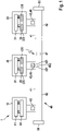
- bus system 1 shows an example of a bus system 1, which is designed in particular fundamentally for a CAN bus system, a CAN FD bus system, a CAN FD successor bus system, which is also referred to as a CAN NG bus system, and/or modifications thereof, as described below.
- the bus system 1 can be used in a vehicle, in particular a motor vehicle, an airplane, etc., or in a hospital, etc.
- the bus system 1 has a large number of subscriber stations 10, 20, 30, which are each connected to a bus 40 with a first bus wire 41 and a second bus wire 42.
- the bus 40 is terminated with terminating resistors 50 at both of its ends.
- the bus cores 41, 42 can also be called CAN_H and CAN_L and are used, using a TX signal in the transmission state, for electrical signal transmission after coupling of the dominant levels or states 401 or generation or active driving of recessive levels or states 402.
- the states 401, 402 are only shown very schematically in the subscriber station 20.
- the states 401, 402 correspond to the states of a TX signal of a transmitting subscriber station 10, 20, 30.
- the signals from the subscriber stations 10, 20, 30 as an RX signal receive After transmission of the signals CAN_H and CAN_L on the bus wires 41, 42, the signals from the subscriber stations 10, 20, 30 as an RX signal receive. Messages 45, 46 in the form of the signals CAN_H and CAN_L can be transmitted serially between the individual subscriber stations 10, 20, 30 via the bus 40. If there is an error in communication on bus 40, as indicated by the jagged black block arrow in 1 shown, an error frame 47 (error flag) is usually sent.
- the subscriber stations 10, 20, 30 are, for example, control units, sensors, display devices, etc. of a motor vehicle.
- the subscriber station 10 has a communication control device 11 and a transmission/reception device 12.
- the subscriber station 20, on the other hand has a communication control device 21 and a transmission/reception device 22 with a transmission/reception unit 220 and an overlay detection unit 230.
- the subscriber station 30 has a communication control device 31 and a transmitting/receiving device 32 with a transmitting/receiving unit 320 and an overlay detection unit 330.
- the transmitting/receiving devices 12, 22, 32 of the subscriber stations 10, 20, 30 are each connected directly to the bus 40, even if this is 1 is not illustrated.
- the communication control devices 11 , 21 , 31 are each used to control communication between the respective subscriber station 10 , 20 , 30 via the bus 40 and another one of the subscriber stations 10 , 20 , 30 which are connected to the bus 40 .
- the communication control device 11 can be designed like a conventional CAN FD controller.
- the communication control device 11 creates and reads first messages 45, which are, for example, CAN FD messages.
- the CAN FD message 45 is constructed according to the CAN FD format, in which a number of up to 64 data bytes can be included, with a clear faster and thus higher data rate than with a classic CAN message.
- the transceiver 12 can be designed like a conventional CAN FD transceiver. It is therefore not necessary to convert the subscriber station 10 in the bus system 1, even if the CAN NG subscriber stations 20, 30 are also operated in the bus system 1.
- Each of the communication control devices 21, 31 create and/or read the first messages 45 or second messages 46.
- the second messages 46 are constructed on the basis of a CAN NG format, which is described in more detail below.
- Each of the transmission/reception devices 22, 32 has a CAN transmission/reception unit 220, 320, which, depending on requirements, sends one of the first messages 45 described above in CAN FD format or a second message 46 in accordance with CAN NG format for the associated communication control device 21, 31 can provide or receive from this.
- the overlay detection units 230, 330 described in more detail below are included.
- CAN NG frame 460 for the message 46, as it is sent by the transceiver 22 or the transceiver 32 as a result of a TX signal as a difference signal on the bus 40 or is received from the bus, from which the RX signal is generated.
- the CAN NG frame 460 is divided into different fields for CAN communication on the bus 40, namely a start field 461, an arbitration field 462, a control field 463, a data field 464, a checksum field 465 and an end field 466.
- a frame for the The first message 45 has the same structure as the frame 460 except for the differences in the control field 463 described below.
- a data phase 468 begins after a particular bit of the control field 463, which is used to switch from the arbitration phase to the data phase 468.
- the data phase 468 includes part of the control field 463 and the Data field 464 and the checksum field 465. All other fields of the frame 460 are part of the arbitration phase 467.
- the start field 461 has a bit, for example, which is also called the SOF bit and indicates the beginning of the frame or start of frame.
- the arbitration field 462 contains an identifier with, for example, 32 bits for identifying the sender of the message.
- the arbitration field 462 and/or the control field 463 can additionally contain protocol format information consisting of one or more bits, which is suitable for distinguishing CAN NG frames from CAN frames or CAN FD frames.
- protocol format information consisting of one or more bits, which is suitable for distinguishing CAN NG frames from CAN frames or CAN FD frames.
- the following description assumes that the CAN NG frame (second message 46) is identical to the frame format for CAN FD (first message 45) up to the FDF bit.
- the control field 463 has a one or more bit protocol format information, which is mentioned above and which is suitable for distinguishing CAN NG frames from Classical CAN frames or CAN FD frames.
- the control field 463 contains, for example, a 12-bit long data length code (data length code) which, for example, can assume values from 1 to 4096 with an increment of 1, or alternatively can assume values from 0 to 4095.
- the data length code may comprise fewer or more bits and the value range and increment may take other values.
- the data field 464 contains the user data of the CAN-NG frame or of the message 46 .
- the user data can have, for example, up to 64 bytes or 4096 bytes or any other number of bytes.
- the checksum field 465 contains a checksum of the data in the data field 464, including the stuff bits, which are inserted by the sender of the message 46 as an inverse bit after, for example, 5 or 10 identical bits.
- At least one acknowledgment bit and one negative acknowledgment bit can be contained in the end field 466 and also a sequence of 11 identical bits which indicate the end E of the CAN NG frame 460 .
- the sending subscriber station can be informed that a receiver has received the received CAN NG frame 460 or message 46 correctly, with the negative acknowledgment bit, the sending subscriber station can be informed whether a receiver in the received CAN NG frame 460 or the message 46 has discovered an error, which can also be referred to as a reception error, or not.
- the control field 463 and the data field 464 are not sent by a sender of the message 46 onto the bus 40 until the subscriber station 20 or the subscriber station 30 as the sender has won the arbitration and the subscriber station 20 or 30 as the sender is then ready to send the fields 463 to 465 has exclusive access to the bus 40 of the bus system 1.
- the identifier in the arbitration field 462 is used to negotiate bit by bit between the subscriber stations 10, 20, 30 which Subscriber station 10, 20, 30 may send the message 45, 46 with the highest priority and therefore gets exclusive access to the bus 40 of the bus system 1 for the next time for sending the fields 463 to 465.
- the arbitration at the beginning of a frame 460 or the message 45, 46 and the acknowledgment in the end field 466 at the end E of the frame 460 or the message 45, 46 is only possible if the bit time is significantly more than twice as long as the signal propagation time between any two subscriber stations 10, 20, 30 of the bus system 1.
- the bit rate in the arbitration phase 467 when transmitting the fields 461, 462, 463 partially and 466 is selected to be slower and therefore lower than in the other fields of the frame 460
- the bit rate in the arbitration phase is chosen as 500 kbit/s, from which a bit time of approximately 2 ⁇ s follows
- the bit rate in the data phase 468 is chosen as, for example, 5 to 8 Mbit/s or greater, from which a bit time of approx. 0.2 ⁇ s and shorter follows.
- the bit time of the signal in the arbitration phase 467 is greater than the bit time of the signal in the data phase 468 by a factor of 10 or 16, etc., for example.
- the factor for the bit time can be selected arbitrarily.
- Each of the subscriber stations 10, 20, 30 can send and receive CAN FD frames, but the subscriber station 10 cannot send or receive CAN NG frames 460.
- the subscriber station 20 sends a CAN NG frame 460 that the CAN FD subscriber station 10 cannot understand, then at least in the case of the CAN NG subscriber station 20 as a transmitter and receiver, optionally also in the case of the CAN NG subscriber station 30 as a pure receiver, the superimposition detection units 230 , 330 active.
- the CAN FD subscriber station 10 does not detect, in particular due to a bit error, that a CAN NG frame 460 is now being sent and an error frame (error flag) is being sent, then there is an overlay of the two physical layers, which is detected by the active overlay detection unit 230, 330 is detected, rectified and signaled to its own node, more precisely the communication control device 21, 31.
- frame format namely the frame 460 of the CAN NG message 46
- res bits in the control field 463 are used to switch from the CAN FD frame format (frame format) to the CAN NG frame format.
- the frame formats of CAN FD and CAN NG are the same up to the res bit.
- the subscriber stations 20, 30 therefore each also support CAN FD. It is then possible to switch to another physical layer that enables a higher bit rate than in the preceding arbitration phase 467 .
- the first bus state 401 is generated for a first digital data state of messages 46 and a second bus state 402 is generated for the second digital data state of messages 46 in such a way that the first bus state 401 can overwrite the second bus state 402 or the dominant bus state can overwrite the recessive bus state.
- the second physical layer can be used to generate different bus states 401, 402 in such a way that the bus states 401, 402 for the different digital data states of the messages 46 cannot overwrite one another. Thus there are no dominant and recessive bus states in the second physical layer.
- res bit In the CAN FD protocol, the res bit is already reserved for new formats.
- the subscriber station 20, 30 transmitting the TX signal or the TX subscriber station sends an error frame 47 (error flag), as in FIG 1 shown, and does not switch to the alternate format according to frame 460.
- error frame 47 error flag
- the treatment of a possible error reaction due to an error in the received signal RX or RX signal in a receiving subscriber station 10, 20, 30 or RX subscriber station takes place with the superposition detection units 230, 330. This is explained below with reference to 3 and 4 described.
- the overlay detection units 230, 330 thus allow the subscriber stations 10, 20, 30 to coexist in the bus system 1, since a subscriber station 10, 20, 30 which has not detected the switchover to the format of the CAN NG frame 460, although an error frame 47 sends, which leads to an overlay of the physical layer, but the overlay is detected and can be turned off.
- an error frame 47 cannot trigger a "short circuit" during the data phase of the CAN NG frame if the transceiver of the sender of the CAN NG frame 460, which is part of the TX node or the TX subscriber station, and the transceiver , which sends the error frame 47 and is part of the RX node or an RX subscriber station, drive against each other.
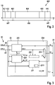
- FIG. 3 12 shows the structure of the superimposition detection unit 230 in the transceiver 22 as an example.
- the superimposition detection unit 330 is designed in the same way, so that the following description also applies to the superimposition detection unit 330.
- FIG. 3 12 shows the structure of the superimposition detection unit 230 in the transceiver 22 as an example.
- the superimposition detection unit 330 is designed in the same way, so that the following description also applies to the superimposition detection unit 330.
- the transmission/reception device 22 has the transmission/reception unit 220, which is designed for the provision of the appropriate physical layer for the various phases of CAN FD messages 45 and CAN NG messages 46 for the bus 40.
- the transmission/reception unit 220 is designed to receive CAN FD messages 45 and to receive CAN NG messages 46 from the bus 40 .
- the transmission/reception unit 220 can in each case switch between the transmission and/or reception of CAN FD messages 45 and the transmission and/or reception of CAN NG messages 46 .
- the transmission/reception unit 220 is connected to the bus cores 41, 42 for receiving the signals CAN_H and CAN_L and is connected to the superimposition detection unit 230.
- the digital TX signal which is also referred to as the transmit signal TXD, is received by the communication controller 21 at the overlay detection unit 230 and output to the transceiver unit 220 .
- the transmitter/receiver unit 220 encodes the TX signal on the physical layer used in each case for the different communication phases, namely arbitration phase 467 or data phase 468 of the messages 45, 46.
- the transmitter/receiver unit 220 decodes the state on the bus 40, ie the signals CAN_H, CAN_L on the bus wires 41, 42, and forwards the result to the overlay detection unit 230 as a digital RXD1 signal.
- the overlay detection unit 230 generates the digital RX signal, which is also referred to as the received signal RXD, from the RXD1 signal.
- the interference detection unit 230 has a data phase detection block 231, a transmitter detection block 232, a collision detection block 233 and a received signal selection block 234. Since the data phase detection block 231 and the transmitter detection block 232 are optional, they are shown.
- the data phase detection block 231 uses the signal RXD1 for this purpose.
- the data phase detection block 231 has a very simplified CAN NG communication control device 2311.
- the CAN NG communication control device 2311 observes the signal RXD1 from the transmission/reception unit 220 and can therefore predict exactly when the data phase 468 begins and when the data phase 468 ends.
- the end of the data phase 468 depends on the number of bytes transferred.
- the number of payload bytes in the data field 464 is encoded at the beginning of the data phase 468 in the data length field.
- the data phase detection block 231 can determine the end of the data phase 468 by counting bits.
- the data phase detection block 231 uses the CAN_H and CAN_L signals to decide whether the data phase 468 is currently occurring. Since CAN NG uses a different physical layer for the data phase 468 than for the arbitration phase 467, different differential voltages VDIFF between CAN_H and CAN_L occur in the data phase 468 of a CAN NG frame 460 than in the data phase 468 of a CAN FD message 45. The data phase Capture block 231 therefore recognizes from the differential voltage of the physical layer used whether the transmission of a CAN NG frame 460 is in the data phase 468.
- the most conservative and therefore safest option is that as soon as one of the detection results from the signal RXD1 and the bus signals CAN_H, CAN_L says that the data phase 468 is present, the data phase detection block 231 assumes this to be true.
- the combination of the two detection results from the signal RXD1 and the bus signals CAN_H, CAN_L is, as a variant for detecting the data phase 468, very robust to disturbances on the bus 40.
- a disturbance could be that a bit error in the RXD1 data stream due to radiation from the communication control device 2311 in the data phase detection block 231 makes believe that the frame 460 is shorter than in reality, or that a CAN FD message 45 is being transmitted.
- the signal NG_DP is optionally forwarded to the communication control device 21 . If the communication control device 21 is only the recipient of the frame 460, the communication control device 21 can use the signal NG_DP to derive why the bus 40 has been blocked for so long, namely by a CAN NG frame 460.
- the transmitter detection block 232 monitors the signal TX, which the communication control unit 21 provides, and counts, for example, the number of edge changes of the signal TX in a predetermined time period T. If more than 0 edge changes have occurred in the predetermined time period T, the transmitter detection block decides 232 that the subscriber station 20, ie its own subscriber station, is currently sending. In order to check this information for plausibility, the transmitter detection block 232 can optionally count the number of edge changes on the signal RXD1 in the predetermined time period T. If the number of edge changes in the signals TX, RXD1 is similar and has at least one value >0, the transmitter detection block 232 decides that the subscriber station 20 is currently transmitting.
- the transmitter detection block 232 can be designed as a counter in order to carry out the detection.
- a counter can be used which is incremented by an edge on the transmission signal TX and is decremented by an edge on the reception signal RX. If the value of the counter is significantly negative, the transmitter detection block 232 determines that the subscriber station 20 is not currently transmitting. Clearly negative means that the transmitter detection block 232 references a predetermined threshold value in making the aforesaid decision. Otherwise, transmitter detection block 232 decides that subscriber-station 20 is currently transmitting. Between two messages 45, 46 the sender detection block 232 resets the counter.
- the collision detection block 233 detects whether during the data phase 468 of a CAN NG frame 460 the bus 40 is also driven by a subscriber station in the CAN FD mode, since this subscriber station namely sends an error frame 47 (error flag), as described above. If this is the case, the collision detection block 233 reacts to this, since during the data phase 468 of a CAN NG frame 46 the physical layer may only be driven by a single CAN NG transceiver, namely the sender of the frame 460. Otherwise, i.e. if during the data phase 468 of a CAN NG frame 460 one of the receiving subscriber stations 10, 20, 30 in CAN FD mode sends an error frame 47 (error flag), then the two physical layers are superimposed.
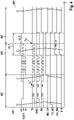
- the bits of frame 460 are now at different levels for at least one of the bus states 401, 402, so that the differential voltage VDIFF between CAN_H and CAN_L is different than they should be in the CAN NG data phase 468. This is in the elliptically framed area U_P of the differential voltage VDIFF from 4 illustrated. The levels are most likely also different from the levels in CAN FD.
- the collision detection block 233 of 3 it is known in which value range the levels are when the physical layer is superimposed. Therefore, the collision detection block 233 can perform a comparison of the levels on the bus 40 with the range of values of the levels in an overlay. Additionally or alternatively, the collision detection block 233 can perform a comparison of the levels on the bus 40 with the value range of the levels in normal operation, ie when there is no superimposition of the physical layer, as in the other ranges of the differential voltage VDIFF from 4 illustrated.
- the collision detection block 233 can detect an overlay of the physical layer in such a way that the collision detection block 233 recognizes that the level for the one bus state 401, 402 no longer appears while the CAN FD node sends its error frame 47 (error flag). This means explicitly that the collision detection block 233 observes whether both bus levels, namely for the bits 0 and 1, ie the bus states 401 and 402, can be seen on the bus 40 during a time x. If the collision detection block 233 only sees the level for one bit, namely for bit 0 or bit 1, then the superimposition of the physical layer for CAN FD on the physical layer for CAN NG has been recorded or detected.
- the collision detection block 233 constantly monitors the level of the individual bits and thus detects whether during the CAN NG data phase 460 a subscriber station 10, 30 in CAN FD mode is sending an error frame 47, as in 4 shown in the area U_P of the differential voltage VDIFF.
- collision detection block 233 detects at least one bus level that indicates an overlay of the physical layer
- collision detection block 233 from 3 optionally consult further information for a plausibility check. At least one of the following possibilities for the plausibility check can optionally be used for this. In particular, it is conceivable to combine the results of individual plausibility checks in a weighted manner in order to arrive at a decision that is as robust as possible with regard to the superimposition of the bus levels.
- the collision detection block 233 takes into account that the bits of a CAN FD error frame 47 are very long compared to the bits in the data phase 468 of the CAN NG frame 460 . Instead of reacting immediately, the collision detection block 233 can continue to monitor the bus level(s) or the bus statuses 401, 402 for an additional observation time T in order to see whether there are still bus levels that indicate an overlap.
- the collision detection block 233 of FIG 3 the signal NG_DP that the data phase detection block 231 generates and outputs to the collision detection block 233 .
- the collision detection block 233 knows from the input signal NG_DP that a transmission on the bus 40 is in the data phase 468 of a frame 460 . Since bus level overlap can only occur during the data phase 468 of a frame 460, the collision detection block 233 can use this knowledge.
- the collision detection block 233 generates the signal S_D.
- the TX_ND signal indicates whether the subscriber-station 20 is currently a TX subscriber-station.
- the signal S_D can be ANDed with the signal TX_ND.
- the collision detection block 233 In order to inform the subscriber stations 20, 30, more precisely their communication control devices 21, 31, about the event of the overlay on the physical layer, the collision detection block 233 generates at least one signal, namely a signal rxd_SW and optionally a signal C_L.
- the received signal selection block 234 can be designed in particular as a multiplexer.
- the signal RX for the own communication control device 21 is set to a fixed value, eg '0', as in FIG 3 shown.
- the signal RX can be set to the fixed value '1'. Because a long phase with only one value, like For example, the value '0', which cannot occur in the CAN NG data phase 468, the CAN NG subscriber station 20, more precisely its communication control device 21, as the sending and receiving subscriber station, recognizes that there was an overlay on the physical layer of the frame 460 . The sending and receiving subscriber station can now react to this information.
- the CAN NG transmission/reception unit 220 of the transmission/reception device 22 and/or the communication control device 21 of the previously transmitting subscriber station 20 can stop transmitting and switch from the data phase 468 to the arbitration phase 467 .
- the CAN NG subscriber station 20 can stop receiving and also switch from the data phase 468 to the arbitration phase 467 .
- all subscriber stations 10, 20, 30 on the bus 40, including the subscriber station 10 (also CAN FD) can wait for a long recessive phase (according to ISO11898-1:2015) before one or more subscriber stations 10, 20, 30 with the Start sending a frame 450, 460.
- the collision detection block 233 and thus the overlay detection unit 230 signals to its own communication control device 21 that an undesired overlay has occurred on the physical layer.
- the communication control device 21 could, for example, itself instruct the transceiver 220 to stop sending.
- FIG. 4 shows an example of the aforementioned signals over the time t for the case that the subscriber station 20 sends a message 46 to the bus 40, ie acts as a TX subscriber station.
- a subscriber station of the bus system for example the subscriber station 30 as the recipient of the message 46, i.e. as an RX subscriber station, incorrectly expects a CAN FD message 45 due to the error represented by the jagged black block arrow, although the CAN NG message 46 is being sent.
- the subscriber station 30 will detect an error in the data phase 468 and send the CAN error frame (error flag) 47 to the bus 40 .
- the RX subscriber stations send the error frame 47 in the period as in 4 marked.
- the signal rxd_SW and RX shows that the superimposition detection unit 230 communicates the superimposition to its own subscriber station, ie the communication control unit 21 here. It can also be seen from the signal TX that the subscriber station 20 stops sending the message 46 from a point in time T5, since the subscriber station 20 has detected a phase in which the signal RX had the value '0' for a long time.
- the data phase detection block 231 performs its detection only on the bus signals CAN_H, CAN_L. Otherwise, the function of the interference detection unit 230 is the same as in the previous embodiment.
- the variant of the data phase detection block 231 according to the present exemplary embodiment is therefore less complex than the variant of the data phase detection block 231 according to the preceding exemplary embodiment.
- a fault that can only be detected by detecting and evaluating the signal TX cannot be located.
- the data phase detection block 231 carries out its detection only on the signal TX. Otherwise, the function of Overlay detection unit 230 as performed in the first embodiment.
- the variant of the data phase detection block 231 according to the present exemplary embodiment is therefore less complex than the variant of the data phase detection block 231 according to the first exemplary embodiment.
- the transmitter detection block 232 is implemented as a simplified CAN NG communication control device which uses the signal TX as an input signal. Due to the sequential decoding of the transmitted CAN NG frame 460, the simplified CAN NG communication control device can very easily and reliably decide whether the subscriber station 20, ie its own subscriber station, is a transmitter or not. For example, if the TX signal remains at a value of 1 from a specific bit during the arbitration phase 467, the simplified CAN NG communication control device infers from this that the subscriber station 20, i.e. its own subscriber station, has lost the arbitration, i.e. is not the sender.
- This configuration of the sender detection block 232 for detecting whether the subscriber station 20 is the sender is more robust or more reliable than the configuration of the sender detection block 232 according to the first exemplary embodiment.
- the present embodiment of the transmitter detection block 232 has a higher resource requirement than the embodiment of the transmitter detection block 232 according to the first embodiment.
- bus system 1 is described using a bus system based on the CAN protocol.
- the bus system 1 according to the exemplary embodiments can also be another type of communication network in which data can be transmitted serially at two different bit rates. It is advantageous, but not an essential requirement, that in the bus system 1 exclusive, collision-free access by a subscriber station 10, 20, 30 to a common channel is guaranteed at least for certain periods of time.
- the number and arrangement of the subscriber stations 10, 20, 30 in the bus system 1 of the exemplary embodiments is arbitrary.
- the subscriber station 10 in the bus system 1 can be omitted.
- the overlay detection units 230, 330 are required if the subscriber stations 20, 30 can also transmit in the CAN FD format, so that the overlays are recognized and dealt with during the data phase 468 of the CAN NG frame 460 when one of the subscriber stations 20, 30 has not successfully switched to the data phase 468 format of the CAN NG frame 460. It is possible for one or more of the subscriber stations 20 or 30 to be present in the bus system 1.
- At least one of the superimposition detection units 230, 330 is arranged externally from the associated transceiver 22, 32.
- at least one of the superposition detection units 230, 330 is provided as a separate unit of the subscriber station 20, 30.
Description
Die vorliegende Erfindung betrifft eine Überlagerungserfassungseinheit für eine Teilnehmerstation eines seriellen Bussystems und ein Verfahren zur Kommunikation in einem seriellen Bussystem, mit welchen eine Kommunikation in dem Bussystem gemäß wahlweise einem ersten Kommunikationsprotokoll oder einem zweiten Kommunikationsprotokoll möglich ist, wobei die Kommunikation gemäß dem zweiten Kommunikationsprotokoll mit einer höheren Bitrate als mit dem ersten Kommunikationsprotokoll und mit einem anderen Physical Layer erfolgt.The present invention relates to an overlay detection unit for a subscriber station of a serial bus system and a method for communication in a serial bus system, with which communication in the bus system is possible according to either a first communication protocol or a second communication protocol, with communication according to the second communication protocol using a higher bit rate than with the first communication protocol and with a different physical layer.
Derzeit wird für die Kommunikation zwischen Sensoren und Steuergeräten, beispielsweise in Fahrzeugen, immer häufiger ein Bussystem eingesetzt, in welchem Daten als Nachrichten im Standard ISO11898-1:2015 als CAN Protokoll-Spezifikation mit CAN FD übertragen werden. Die Nachrichten werden zwischen den Teilnehmerstationen des Bussystems, wie Sensor, Steuergerät, Geber, usw., übertragen. Hierbei wird CAN FD derzeit in der Einführungsphase im ersten Schritt meist mit einer Daten-Bitrate von 2Mbit/s bei der Übertragung von Bits des Datenfelds und mit einer Arbitrations-Bitrate von 500kbit/s bei der Übertragung aller anderen Bits, insbesondere der Bits des Arbitrationsfelds, im Fahrzeug eingesetzt.A bus system in which data is transmitted as messages in the ISO11898-1:2015 standard as a CAN protocol specification with CAN FD is currently being used more and more frequently for communication between sensors and control units, for example in vehicles. The messages are transmitted between the bus system subscriber stations, such as sensors, control units, encoders, etc. Here, CAN FD is currently in the introductory phase in the first step mostly with a data bit rate of 2Mbit/s for the transmission of bits of the data field and with an arbitration bit rate of 500kbit/s for the transmission of all other bits, especially the bits of the arbitration field , used in the vehicle.
Sowohl bei der Übertragung des Arbitrationsfelds als auch bei der Übertragung des Datenfelds wird derselbe Physical Layer verwendet, welcher der Bitübertragungsschicht oder Schicht 1 des bekannten OSI-Modells (Open Systems Interconnection Modell) entspricht. Dabei werden zwei Buszustände unterschieden, nämlich "dominant" (entspricht der logischen bzw. digitalen 0) und "rezessiv" (entspricht der logischen bzw. digitalen 1). Da der rezessive Buszustand nicht aktiv getrieben wird, kann der rezessive Buszustand von dem dominanten Buszustand überschrieben werden, wodurch die Arbitration ermöglicht wird. Jedoch wird der rezessive Buszustand nur relativ langsam durch Abschlusswiderstände des Bussystems eingestellt. Dies verhindert auf der einen Seite eine schnellere Datenübertragung. Auf der anderen Seite gewährleistet die Arbitration gemäß dem oben genannten Standard ISO11898-1:2015 jedoch, dass während der Übertragung des Datenfelds nur eine der Teilnehmerstationen ihre Daten exklusiv und kollisionsfrei sendet. Dadurch sind Daten nach der Arbitration sicherer ohne Notwendigkeit der Wiederholung über den Bus übertragbar. Dies trägt insgesamt mit zu einer Beschleunigung der Datenübertragung bei.The same physical layer is used for both the transmission of the arbitration field and the transmission of the data field Physical layer or layer 1 of the well-known OSI model (Open Systems Interconnection Model). A distinction is made between two bus states, namely "dominant" (corresponds to the logical or digital 0) and "recessive" (corresponds to the logical or digital 1). Because the recessive bus state is not actively driven, the recessive bus state can be overwritten by the dominant bus state, allowing arbitration. However, the recessive bus status is set relatively slowly by the terminating resistors of the bus system. On the one hand, this prevents faster data transmission. On the other hand, however, arbitration in accordance with the above-mentioned ISO11898-1:2015 standard ensures that only one of the subscriber stations sends its data exclusively and collision-free during the transmission of the data field. As a result, data can be transmitted more securely over the bus after arbitration without the need for repetition. Overall, this contributes to accelerating the data transmission.
Soll also der Vorteil der Arbitration beibehalten werden und dennoch die Übertragungsrate noch weiter als bisher erhöht werden, muss eine Lösung gefunden werden, welche die Nachteile der langsamen Übertragungsrate bei der Arbitration gemäß dem oben genannten Standard ISO11898-1:2015 vermindert. Dabei soll für eine einfache Migration bestehender Bussysteme außerdem ermöglicht werden, dass Teilnehmerstationen, die noch gemäß den bestehenden CAN-Protokoll-Spezifikationen arbeiten, im Bussystem auch mit Teilnehmerstationen koexistieren können, die bereits gemäß einer Nachfolge-CAN-Protokoll-Spezifikation kommunizieren.If the advantage of arbitration is to be retained and the transmission rate increased further than before, a solution must be found that reduces the disadvantages of the slow transmission rate during arbitration in accordance with the ISO11898-1:2015 standard mentioned above. For a simple migration of existing bus systems, it should also be made possible for subscriber stations that still work according to the existing CAN protocol specifications to also be able to coexist in the bus system with subscriber stations that already communicate according to a subsequent CAN protocol specification.
Aus dem Stand der Technik sind Transceiver mit ähnlichen Eigenschaften bekannt. Die
Daher ist es Aufgabe der vorliegenden Erfindung, eine Überlagerungserfassungseinheit für eine Teilnehmerstation eines seriellen Bussystems und ein Verfahren zur Kommunikation in einem seriellen Bussystem bereitzustellen, welche die zuvor genannten Probleme lösen. Insbesondere sollen eine Überlagerungserfassungseinheit für eine Teilnehmerstation eines seriellen Bussystems und ein Verfahren zur Kommunikation in einem seriellen Bussystem bereitgestellt werden, bei welchen auch eine Koexistenz von Teilnehmerstationen möglich ist, die gemäß dem Standard ISO11898-1:2015 oder gemäß einer Nachfolge-CAN-Protokoll-Spezifikation kommunizieren.It is therefore the object of the present invention to provide an interference detection unit for a subscriber station of a serial bus system and a method for communication in a serial bus system, which solve the aforementioned problems. In particular, an overlay detection unit for a subscriber station of a serial bus system and a method for communication in a serial bus system are to be provided, in which a coexistence of subscriber stations is also possible, which according to the standard ISO11898-1:2015 or according to a successor CAN protocol communicate specification.
Die Aufgabe wird durch eine Überlagerungserfassungseinheit für eine Teilnehmerstation eines seriellen Bussystems mit den Merkmalen von Anspruch 1 gelöst. Die Überlagerungserfassungseinheit hat einen Kollisionserfassungsblock zur Erfassung von Buszuständen auf einem Bus des Bussystems, bei welchem Buszustände von Teilnehmerstationen des Bussystems zum Senden einer Nachricht in einer ersten Kommunikationsphase auf dem Bus mit einem ersten Physical Layer erzeugt werden und in einer zweiten Kommunikationsphase mit einem zweiten Physical Layer erzeugt werden können, der sich von dem ersten Physical Layer unterscheidet, wobei der Kollisionserfassungsblock zur Erzeugung eines Signals ausgestaltet ist, dessen Wert angibt, ob die Buszustände in der zweiten Kommunikationsphase einen Pegel haben, der einer Überlagerung des ersten und zweiten Physical Layers oder einer Überlagerung von zwei zweiten Physical Layern entspricht oder nicht, und wobei der Kollisionserfassungsblock zur Ausgabe des Signals für die Teilnehmerstation ausgestaltet ist.The object is achieved by an overlay detection unit for a subscriber station of a serial bus system having the features of claim 1. The overlay detection unit has a collision detection block for detecting bus states on a bus of the bus system, in which bus states of subscriber stations of the bus system for sending a message are generated in a first communication phase on the bus with a first physical layer and in a second communication phase with a second physical layer can be generated, which differs from the first physical layer, wherein the collision detection block is arranged to generate a signal, the value of which indicates whether the bus states in the second communication phase have a level corresponding to an overlay of the first and second physical layers or an overlay of two second physical layers or not, and wherein the collision detection block is designed to output the signal for the subscriber station.
Hierbei bedeutet "Überlagerung des ersten und zweiten Physical Layers", dass wenigstens ein Buszustand beobachtet wird, welcher einer Überlagerung von einem oder mehreren Buszuständen, die durch eine erste Teilnehmerstation mittels der ersten Physical Layer erzeugt werden, mit einem oder mehreren Buszuständen, die durch eine zweite Teilnehmerstation mittels der zweiten Physical Layer erzeugt werden, entspricht.In this context, "superimposition of the first and second physical layers" means that at least one bus status is observed, which is a superimposition of one or more bus statuses that are generated by a first subscriber station using the first physical layer, with one or more bus statuses that are generated by a second subscriber station are generated by means of the second physical layer corresponds.
Weiterhin bedeutet "Überlagerung von zwei zweiten Physical Layern", dass wenigstens ein Buszustand beobachtet wird, welcher einer Überlagerung von einem oder mehreren Buszuständen, die durch eine dritte Teilnehmerstation mittels der zweiten Physical Layer erzeugt werden, mit einem oder mehreren Buszuständen, die durch eine vierte Teilnehmerstation mittels der zweiten Physical Layer erzeugt werden, entspricht.Furthermore, "superimposition of two second physical layers" means that at least one bus status is observed, which is a superimposition of one or more bus statuses generated by a third subscriber station using the second physical layer, with one or more bus statuses generated by a fourth Subscriber station are generated by means of the second physical layer corresponds.
Mit der Überlagerungserfassungseinheit wird ermöglicht, dass erste Teilnehmerstationen des Bussystems, die in einer ersten Kommunikationsphase das gleiche Kommunikationsformat verwenden wie zweite Teilnehmerstationen, jedoch in einer zweiten Kommunikationsphase ein anderes Kommunikationsformat verwenden als die zweiten Teilnehmerstationen, die Kommunikation der zweiten Teilnehmerstationen zwar stören können, jedoch die Störung schnell behoben werden kann. Hierfür kann die Überlagerungserfassungseinheit auf dem Bus eine Überlagerung von Physical Layern erfassen, die beispielsweise durch Überlagerung von gesendeter Nachricht mit Fehlerrahmen (Error-Flags) auftritt. Hierbei wurden die Fehlerrahmen gesendet, da eine Teilnehmerstation des Bussystems nicht erfasst hat, dass derzeit eine Kommunikation der zweiten Teilnehmerstationen mit einem Kommunikationsformat stattfindet, das sich von dem Kommunikationsformat des gesendeten Fehlerrahmens unterscheidet. Insbesondere kann die Überlagerungserfassungseinheit Fehlerrahmen (Error-Flags) erfassen, welche in einem Kommunikationsformat auf den Bus gesendet werden, das sich von dem Kommunikationsformat unterscheidet, in welchem die eigene Teilnehmerstation derzeit in der zweiten Kommunikationsphase auf den Bus sendet.The superposition detection unit makes it possible for first subscriber stations of the bus system, which use the same communication format as second subscriber stations in a first communication phase, but use a different communication format than the second subscriber stations in a second communication phase, to be able to disrupt the communication of the second subscriber stations, but to fault can be rectified quickly. For this purpose, the superimposition detection unit on the bus can detect superimposition of physical layers, which occurs, for example, due to superimposition of transmitted messages with error frames (error flags). In this case, the error frames were sent because a subscriber station of the bus system has not detected that the second subscriber stations are currently communicating with a communication format that differs from the communication format of the error frame sent. In particular, the overlay detection unit can detect error frames (error flags) which are sent on the bus in a communication format which differs from the communication format in which the subscriber station's own station is currently sending on the bus in the second communication phase.
Die Überlagerungserfassungseinheit stellt also die benötigte Information bereit, dass die eigene Sende- / Empfangseinrichtung sofort das Treiben eines Signals für den Rahmen auf den Bus in der zweiten Kommunikationsphase des Rahmens einstellen kann. Dadurch werden/wird ein Kurzschluss und/oder hohe Ströme auf dem Bus vermieden. Darüber hinaus kann die Sende-/ Empfangseinrichtung die Information über den erfassten Fehlerrahmen an die eigene Kommunikationssteuereinrichtung weitergeben, damit auch die eigene Kommunikationssteuereinrichtung das Senden und/oder Empfangen des Rahmens abbricht.The overlay detection unit thus provides the information required so that its own transceiver can immediately stop driving a signal for the frame onto the bus in the second communication phase of the frame. This avoids a short circuit and/or high currents on the bus. In addition, the transmitting/receiving device can pass on the information about the detected error frame to its own communication control device, and thus also to its own Communication control device sending and / or receiving the frame stops.
Die Überlagerungserfassungseinheit ist jedoch derart ausgestaltet, dass die Verwendung von Fehlerrahmen (Error-Flags) in der Arbitrationsphase als erster Kommunikationsphase möglich ist.However, the overlay detection unit is designed in such a way that the use of error frames (error flags) in the arbitration phase as the first communication phase is possible.
Somit ist in einer ersten Kommunikationsphase eine von CAN bekannte Arbitration durchführbar und dennoch in einer zweiten Kommunikationsphase die Übertragungsrate gegenüber CAN FD beträchtlich steigerbar. Dadurch kann auch bei Verwendung von unterschiedlichen Physical Layern in der Datenphase als der zweiten Kommunikationsphase eine Kommunikation von Fehlern via Fehlerrahmen (Error-Flags) in der Arbitrationsphase und der Datenphase durchgeführt werden.Thus, in a first communication phase, an arbitration known from CAN can be carried out and yet in a second communication phase the transmission rate can be increased considerably compared to CAN FD. As a result, even when using different physical layers in the data phase as the second communication phase, errors can be communicated via error frames (error flags) in the arbitration phase and the data phase.
Die Teilnehmerstation ermöglicht, dass durch ein Senden des in CAN FD vorhandenen "res-Bit:=1" zu einem neuen Rahmenformat umgeschaltet werden kann und danach aufgrund der Überlagerungserfassungseinheit Fehler aufgrund von Überlagerung von Physical Layer Signalen erkannt werden und an den eigenen Knoten kommuniziert werden können, um den Fehler zu behandeln.The subscriber station makes it possible to switch to a new frame format by sending the "res-Bit:=1" present in CAN FD and then, due to the overlay detection unit, errors due to overlaying of physical layer signals are detected and communicated to their own nodes can to handle the error.
Durch die Koexistenz und Interoperabilität von Teilnehmerstationen, die gemäß dem CAN FD -Kommunikationsprotokoll arbeiten, und Teilnehmerstationen, die gemäß einem CAN FD Nachfolger-Kommunikationsprotokoll arbeiten, das nachfolgend CAN NG genannt ist, ist ein nahtloser Migrationspfad von CAN FD zu CAN NG hin möglich. Somit können einzelne Teilnehmerstationen des Bussystems, die weiterhin nur CAN FD verwenden sollen, unverändert bleiben, wohingegen die CAN NG Teilnehmerstationen, die auch CAN FD Rahmen senden und empfangen können, mit der Überlagerungserfassungseinheit ausgestattet werden. Daher sind keine Gateways zwischen CAN FD und CAN NG Bussystemen erforderlich.Due to the coexistence and interoperability of subscriber stations that work according to the CAN FD communication protocol and subscriber stations that work according to a CAN FD successor communication protocol, hereinafter referred to as CAN NG, a seamless migration path from CAN FD to CAN NG is possible. Thus, individual subscriber stations of the bus system that are only to continue to use CAN FD can remain unchanged, whereas the CAN NG subscriber stations that can also send and receive CAN FD frames are equipped with the superimposition detection unit. Therefore, no gateways between CAN FD and CAN NG bus systems are required.
Die zuvor beschriebene Überlagerungserfassungseinheit kann einen Busfehler ohne Datenüberhang (Daten-Overhead) erkennen. Daher muss die korrekte Formatumschaltung aller Teilnehmerstationen nicht in mindestens einem Bit des Rahmens codiert werden, um die korrekte Formatumschaltung abprüfen zu können. Dadurch bietet die Überlagerungserfassungseinheit eine sehr effiziente und robuste Möglichkeit, mit Busfehlern aufgrund und/oder während der Formatumschaltung eines Rahmens umzugehen. Dadurch wird ein großer Datenüberhang in jedem Rahmen vermieden. Ein solcher Datenüberhang wäre noch dazu nachteilig, da Busfehler bei CAN praktisch nicht auftreten, jedoch nicht auszuschließen und daher zu behandeln sind.The interference detection unit described above can detect a bus error without data overhead. Therefore, the correct format switching of all subscriber stations does not have to be in at least one bit of the Frames are encoded in order to be able to check the correct format switching. As a result, the interference detection unit offers a very efficient and robust way of dealing with bus errors due to and/or during a frame's format switch. This avoids a large data overhead in each frame. Such a data overhang would also be disadvantageous, since bus errors practically do not occur with CAN, but cannot be ruled out and must therefore be dealt with.
Vorteilhafte weitere Ausgestaltungen der Überlagerungserfassungseinheit sind in den abhängigen Ansprüchen angegeben.Advantageous further refinements of the superimposition detection unit are specified in the dependent claims.
Gemäß einer Option ist der Kollisionserfassungsblock ausgestaltet zu erfassen, ob Bits für einen Rahmen der Nachricht andere Pegel haben als die Pegel in der zweiten Kommunikationsphase üblicherweise haben. Alternativ oder zusätzlich ist der Kollisionserfassungsblock ausgestaltet zu erfassen, ob in der zweiten Kommunikationsphase für ein digitales Signal für einen Rahmen der Nachricht zwei verschiedene Buszustände auf dem Bus vorkommen oder nicht.According to one option, the collision detection block is designed to detect whether bits for a frame of the message have different levels than the levels usually have in the second communication phase. Alternatively or additionally, the collision detection block is designed to detect whether or not two different bus states occur on the bus in the second communication phase for a digital signal for a frame of the message.
Möglicherweise ist der Kollisionserfassungsblock ausgestaltet, eine Plausibilisierung einer erfassten Überlagerung durchzuführen, um zu entscheiden, ob der Wert des Signals auf einen Wert zu setzen ist, der eine Überlagerung anzeigt.The collision detection block may be designed to perform a plausibility check on a detected overlay in order to decide whether the value of the signal is to be set to a value that indicates an overlay.
Denkbar ist, dass der Kollisionserfassungsblock ausgestaltet ist, die Plausibilisierung mit Hilfe von mindestens zwei verschiedenen Varianten durchzuführen, die unterschiedlich gewichtet werden, um zu entscheiden, ob die Überlagerung auftritt oder nicht.It is conceivable that the collision detection block is designed to carry out the plausibility check using at least two different variants, which are weighted differently in order to decide whether the superimposition occurs or not.
Denkbar ist zudem, dass die Überlagerungserfassungseinheit außerdem einen Empfangssignal-Auswahlblock zur Auswahl eines Empfangssignals auf der Grundlage des von dem Kollisionserfassungsblock erzeugten Signals und zur Ausgabe des ausgewählten Empfangssignals an eine Kommunikationssteuereinrichtung der Teilnehmerstation aufweist.It is also conceivable that the interference detection unit also has a received signal selection block for selecting a received signal on the basis of the signal generated by the collision detection block and for outputting the selected received signal to a communication control device of the subscriber station.
Die zuvor beschriebene Überlagerungserfassungseinheit hat gemäß einer speziellen Ausführungsvariante einen Datenphase-Erfassungsblock zur Erfassung der Datenphase der auf dem Bus seriell übertragenen Nachricht, und/oder einen Sender-Erfassungsblock zur Erfassung, ob die Teilnehmerstation derzeit der Sender der Nachricht ist oder nicht, wobei der Kollisionserfassungsblock ausgestaltet ist, das Signal als Reaktion auf mindestens ein Erfassungsergebnis zu erzeugen, das der Kollisionserfassungsblock von dem Datenphase -Erfassungsblock und/oder dem Sender-Erfassungsblock empfangen hat.According to a special embodiment variant, the previously described interference detection unit has a data phase detection block for detecting the data phase of the message serially transmitted on the bus, and/or a sender detection block for detecting whether the subscriber station is currently the sender of the message or not, the collision detection block is configured to generate the signal in response to at least one detection result received by the collision detection block from the data phase detection block and/or the transmitter detection block.
Gemäß einer Option ist der Datenphase-Erfassungsblock ausgestaltet, zur Erfassung der Datenphase einen Zustand auf dem Bus zu erfassen. Gemäß einer anderen Option ist der Datenphase -Erfassungsblock ausgestaltet, zur Erfassung der Datenphase ein digitales Empfangssignal auszuwerten, das aus der vom Bus empfangenen Nachricht erzeugt wird.According to one option, the data phase detection block is configured to detect a state on the bus to detect the data phase. According to another option, the data phase detection block is designed to evaluate a digital received signal, which is generated from the message received from the bus, in order to detect the data phase.
Möglicherweise ist der Sender-Erfassungsblock ausgestaltet, ein Sendesignal auszuwerten, das von der Teilnehmerstation zu dem Bus gesendet wird. Hierbei kann der Sender-Erfassungsblock ausgestaltet sein, zur Auswertung des Sendesignals Flankenwechsel des Sendesignals zu zählen. Alternativ oder zusätzlich kann der Sender-Erfassungsblock ausgestaltet sein, zur Auswertung des Sendesignals eine sequentielle Dekodierung des Sendesignals auszuführen. Alternativ oder zusätzlich kann der Sender-Erfassungsblock ausgestaltet sein, zur Auswertung des Sendesignals das Sendesignal mit einem digitalen Empfangssignal zu vergleichen, das aus der vom Bus empfangenen Nachricht erzeugt wird.The transmitter detection block may be designed to evaluate a transmission signal that is sent from the subscriber station to the bus. In this case, the transmitter detection block can be designed to count edge changes in the transmission signal for evaluating the transmission signal. As an alternative or in addition, the transmitter detection block can be designed to carry out a sequential decoding of the transmission signal in order to evaluate the transmission signal. Alternatively or additionally, the transmitter detection block can be designed to compare the transmission signal with a digital reception signal, which is generated from the message received from the bus, in order to evaluate the transmission signal.
Möglicherweise wird in einer ersten Kommunikationsphase zur Übertragung der Nachricht auf den Bus zwischen den Teilnehmerstationen des Bussystems ausgehandelt, welche der Teilnehmerstationen in einer nachfolgenden zweiten Kommunikationsphase zumindest zeitweise einen exklusiven, kollisionsfreien Zugriff auf den Bus des Bussystems hat, wobei die zweite Kommunikationsphase eine Datenphase ist, in welcher Nutzdaten der Nachricht auf dem Bus übertragen werden.Possibly, in a first communication phase for the transmission of the message on the bus between the subscriber stations of the bus system, it is negotiated which of the subscriber stations has at least temporarily exclusive, collision-free access to the bus of the bus system in a subsequent second communication phase, the second communication phase being a data phase, in which user data of the message is transmitted on the bus.
Die zuvor beschriebene Überlagerungserfassungseinheit kann Teil einer Teilnehmerstation für ein serielles Bussystem sein, wobei die Teilnehmerstation zudem aufweist eine Kommunikationssteuereinrichtung zum Senden einer Nachricht zu einem Bus des Bussystems und/oder zum Empfangen einer Nachricht von dem Bus des Bussystems, und eine Sende- / Empfangseinrichtung zum Senden der Nachricht auf den Bus und/oder Empfangen der Nachricht von dem Bus, wobei die Überlagerungserfassungseinheit mit der Kommunikationssteuereinrichtung und der Sende- / Empfangseinrichtung verschaltet ist, wobei die Sende- / Empfangseinrichtung ausgestaltet ist, beim Senden mit einer ersten Bitrate, einen ersten Buszustand für einen ersten digitalen Datenzustand der Nachrichten zu erzeugen und einen zweiten Buszustand für den zweiten digitalen Datenzustand der Nachrichten derart zu erzeugen, dass der zweite Buszustand den ersten Buszustand überschreiben kann, und wobei die Sende- / Empfangseinrichtung ausgestaltet ist, beim Senden mit einer zweiten Bitrate, die höher ist als die erste Bitrate, unterschiedliche Buszustände derart zu erzeugen, dass die Buszustände für die unterschiedlichen digitalen Datenzustände der Nachrichten einander nicht überschreiben können.The interference detection unit described above can be part of a subscriber station for a serial bus system, the subscriber station also having a communication control device for sending a message to a bus of the bus system and/or for receiving a message from the bus of the bus system, and a transceiver for Sending the message on the bus and/or receiving the message from the bus, the overlay detection unit being connected to the communication control device and the transceiver, the transceiver being configured, when sending at a first bit rate, a first bus state to generate a first digital data state of the messages and to generate a second bus state for the second digital data state of the messages in such a way that the second bus state can overwrite the first bus state, and wherein the transmitting/receiving device is designed, when sending at a second bit rate that is higher than the first bit rate, to generate different bus states in such a way that the bus states for the different digital data states of the messages cannot overwrite one another.
Zudem kann die Sende- / Empfangseinrichtung ausgestaltet sein, beim Senden mit der zweiten Bitrate unterschiedliche Buszustände derart zu erzeugen, dass die Buszustände für die unterschiedlichen digitalen Datenzustände der Nachrichten einander nicht überschreiben können, oder beim Senden mit der zweiten Bitrate die unterschiedlichen Buszustände zu erzeugen wie beim Senden mit der ersten Bitrate.In addition, the transmitting/receiving device can be configured to generate different bus statuses when sending at the second bit rate in such a way that the bus statuses for the different digital data statuses of the messages cannot overwrite one another, or to generate the different bus statuses when sending at the second bit rate when sending at the first bitrate.
Mindestens zwei zuvor beschriebene Teilnehmerstationen können Teil eines Bussystems sein, das zudem einen Bus aufweist, so dass die mindestens zwei Teilnehmerstationen über den Bus derart miteinander verbunden sind, dass sie seriell miteinander kommunizieren können. Hierbei ist mindestens eine der mindestens zwei Teilnehmerstationen eine zuvor beschriebene Teilnehmerstation.At least two subscriber stations described above can be part of a bus system which also has a bus, so that the at least two subscriber stations are connected to one another via the bus in such a way that they can communicate with one another in series. In this case, at least one of the at least two subscriber stations is a previously described subscriber station.
Das zuvor beschriebene Bussystem hat möglicherweise zudem mindestens eine zusätzliche Teilnehmerstation, welche zur Übertragung der Nachricht auf dem Bus nur ausgestaltet ist, in einer ersten und zweiten Kommunikationsphase der Nachricht Buszustände derart auf dem Bus zu erzeugen, dass der zweite Buszustand den ersten Buszustand überschreiben kann, wobei die mindestens eine zusätzliche Teilnehmerstation über den Bus mit den mindestens zwei Teilnehmerstationen derart verbunden ist, dass die Teilnehmerstationen seriell miteinander kommunizieren können.The bus system described above may also have at least one additional subscriber station, which is only designed to transmit the message on the bus in a first and second communication phase Message to generate bus states on the bus in such a way that the second bus state can overwrite the first bus state, the at least one additional subscriber station being connected to the at least two subscriber stations via the bus in such a way that the subscriber stations can communicate with one another serially.
Die zuvor genannte Aufgabe wird zudem durch ein Verfahren zur Kommunikation in einem seriellen Bussystem nach Anspruch 15 gelöst. Das Verfahren hat die Schritte: Senden, mit einer Sende- / Empfangseinrichtung, von Nachrichten auf einen Bus des Bussystems, bei welchem Buszustände von Teilnehmerstationen des Bussystems zum Senden einer Nachricht in einer ersten Kommunikationsphase auf dem Bus mit einem ersten Physical Layer erzeugt werden und in einer zweiten Kommunikationsphase mit einem zweiten Physical Layer erzeugt werden, der sich von dem ersten Physical Layer unterscheidet, und/oder Empfangen, mit der Sende- / Empfangseinrichtung, von Nachrichten von dem Bus des Bussystems, Erfassen, mit einem Kollisionserfassungsblock, von Buszuständen auf dem Bus des Bussystems, Erzeugen, mit dem Kollisionserfassungsblock, eines Signals, dessen Wert angibt, ob die Buszustände in der zweiten Kommunikationsphase einen Pegel haben, der einer Überlagerung des ersten und zweiten Physical Layers oder einer Überlagerung von zwei zweiten Physical Layern entspricht oder nicht, und Ausgeben, mit dem Kollisionserfassungsblock, des Signals für die Teilnehmerstation.The aforementioned object is also achieved by a method for communication in a serial bus system according to claim 15. The method has the steps: sending, with a transmitting/receiving device, of messages on a bus of the bus system, in which bus states of subscriber stations of the bus system for sending a message are generated in a first communication phase on the bus with a first physical layer and in a second communication phase with a second physical layer, which differs from the first physical layer, and/or receiving, with the transceiver, of messages from the bus of the bus system, detecting, with a collision detection block, of bus states on the Bus of the bus system, generating, with the collision detection block, a signal whose value indicates whether the bus states in the second communication phase have a level corresponding or not to an overlap of the first and second physical layers or to an overlap of two second physical layers, and Output, with the collision detection block, of the Sig than for the subscriber station.
Das Verfahren bietet dieselben Vorteile, wie sie zuvor in Bezug auf die Teilnehmerstation genannt sind.The method offers the same advantages as previously mentioned in relation to the subscriber station.
Weitere mögliche Implementierungen der Erfindung umfassen auch nicht explizit genannte Kombinationen von zuvor oder im Folgenden bezüglich der Ausführungsbeispiele beschriebenen Merkmale oder Ausführungsformen. Dabei wird der Fachmann auch Einzelaspekte als Verbesserungen oder Ergänzungen zu der jeweiligen Grundform der Erfindung hinzufügen.Further possible implementations of the invention also include combinations of features or embodiments described above or below with regard to the exemplary embodiments that are not explicitly mentioned. The person skilled in the art will also add individual aspects as improvements or additions to the respective basic form of the invention.
Nachfolgend ist die Erfindung unter Bezugnahme auf die beiliegende Zeichnung und anhand von Ausführungsbeispielen näher beschrieben. Es zeigen:
-
Fig. 1 ein vereinfachtes Blockschaltbild eines Bussystems gemäß einem ersten Ausführungsbeispiel; -
Fig. 2 ein Schaubild zur Veranschaulichung des Aufbaus von Nachrichten, die von Teilnehmerstationen des Bussystems gemäß dem ersten Ausführungsbeispiel gesendet werden können; -
Fig. 3 ein Schaubild zur Veranschaulichung des Aufbaus einer Überlagerungserfassungseinheit, die bei Teilnehmerstationen des Bussystems gemäß dem ersten Ausführungsbeispiel eingebaut ist; und -
Fig. 4 ein Signalzeitdiagramm für verschiedene Signale, die im Betrieb des Bussystems gemäß dem ersten Ausführungsbeispiel gesendet werden.
-
1 a simplified block diagram of a bus system according to a first embodiment; -
2 a diagram to illustrate the structure of messages that can be sent by subscriber stations of the bus system according to the first embodiment; -
3 a diagram for illustrating the structure of an interference detection unit, which is installed in subscriber stations of the bus system according to the first embodiment; and -
4 a signal timing diagram for various signals that are sent during operation of the bus system according to the first embodiment.
In den Figuren sind gleiche oder funktionsgleiche Elemente, sofern nichts Anderes angegeben ist, mit denselben Bezugszeichen versehen.In the figures, elements that are the same or have the same function are provided with the same reference symbols unless otherwise stated.
In
Wie in
Die Kommunikationssteuereinrichtungen 11, 21, 31 dienen jeweils zur Steuerung einer Kommunikation der jeweiligen Teilnehmerstation 10, 20, 30 über den Bus 40 mit einer anderen Teilnehmerstation der Teilnehmerstationen 10, 20, 30, die an den Bus 40 angeschlossen sind.The
Die Kommunikationssteuereinrichtung 11 kann wie ein herkömmlicher CAN FD-Controller ausgeführt sein. Die Kommunikationssteuereinrichtung 11 erstellt und liest erste Nachrichten 45, die beispielsweise CAN FD Nachrichten sind. Die CAN FD Nachricht 45 ist gemäß dem CAN FD Format aufgebaut, bei welcher eine Anzahl von bis zu 64 Datenbytes umfasst sein können, die mit einer deutlich schnelleren und damit höheren Datenrate als bei einer Classical CAN-Nachricht übertragen werden. Die Sende- / Empfangseinrichtung 12 kann wie ein herkömmlicher CAN FD Transceiver ausgeführt sein. Somit ist eine Umrüstung der Teilnehmerstation 10 in dem Bussystem 1 nicht erforderlich, auch wenn in dem Bussystem 1 auch die CAN NG Teilnehmerstationen 20, 30 betrieben werden.The
Jede der Kommunikationssteuereinrichtungen 21, 31 erstellen und/oder lesen die ersten Nachrichten 45 oder zweite Nachrichten 46. Die zweiten Nachrichten 46 sind auf der Grundlage eines CAN NG-Formats aufgebaut, das nachfolgend detaillierter beschrieben ist. Jede der Sende- / Empfangseinrichtungen 22, 32 hat eine CAN Sende- / Empfangseinheit 220, 320, die je nach Bedarf eine der zuvor beschriebenen ersten Nachrichten 45 im CAN FD Format oder eine zweite Nachricht 46 gemäß dem CAN NG-Format für die zugehörige Kommunikationssteuereinrichtung 21, 31 bereitstellen oder von dieser empfangen kann. Zusätzlich sind die nachfolgend noch genauer beschriebenen Überlagerungserfassungseinheiten 230, 330 umfasst.Each of the
Mit den beiden Teilnehmerstationen 20, 30 ist eine Bildung und dann Übertragung von Nachrichten 46 mit dem CAN NG Format sowie der Empfang solcher Nachrichten 46 realisierbar.With the two
Das Startfeld 461 hat beispielsweise ein Bit, das auch SOF-Bit genannt wird und den Beginn des Rahmens bzw. Start of Frame anzeigt. In dem Arbitrationsfeld 462 ist ein Identifizierer mit beispielsweise 32 Bit zur Identifikation des Senders der Nachricht enthalten.The
Das Arbitrationsfeld 462 und/oder das Steuerfeld 463 kann zusätzlich eine aus einem oder mehreren Bits bestehende Protokollformatinformation enthalten, welche geeignet ist, CAN NG-Rahmen gegenüber CAN-Rahmen oder CAN FD-Rahmen zu unterscheiden. Die nachfolgende Beschreibung geht jedoch davon aus, dass der CAN NG Rahmen (zweite Nachricht 46) bis zum FDF-Bit identisch zu dem Rahmenformat bei CAN FD (erste Nachricht 45) ist.The
Das Steuerfeld 463 hat eine aus einem oder mehreren Bits bestehende Protokollformatinformation, welche zuvor genannt ist und welche geeignet ist, CAN NG-Rahmen gegenüber Classical CAN-Rahmen oder CAN FD-Rahmen zu unterscheiden. In dem Steuerfeld 463 ist ein beispielsweise 12 Bit langer Datenlängecode (Data-Length-Code) enthalten, der zum Beispiel Werte von 1 bis zu 4096 mit der Schrittweite von 1 annehmen kann, oder alternativ Werte von 0 bis 4095 annehmen kann. Der Datenlängecode kann alternativ weniger oder mehr Bits umfassen und der Wertebereich und die Schrittweite können andere Werte annehmen.The
In dem Datenfeld 464 sind die Nutzdaten des CAN-NG-Rahmens bzw. der Nachricht 46 enthalten. Die Nutzdaten können entsprechend dem Wertebereich des Datenlängecodes beispielsweise bis zu 64 Bytes oder 4096 Bytes oder eine beliebige andere Anzahl von Bytes aufweisen.The
In dem Prüfsummenfeld 465 ist eine Prüfsumme über die Daten in dem Datenfeld 464 einschließlich der Stuffbits enthalten, die vom Sender der Nachricht 46 nach z.B. jeweils 5 oder 10 gleichen Bits als inverses Bit eingefügt werden.The
In dem Endefeld 466 kann mindestens ein Acknowledge-Bit und ein Negativ Acknowledge-Bit enthalten sein und außerdem eine Folge von 11 gleichen Bits, welche das Ende E des CAN NG Rahmens 460 anzeigen. Mit dem mindestens einen Acknowledge-Bit kann der sendenden Teilnehmerstation mitgeteilt werden, dass ein Empfänger den empfangenen CAN NG Rahmen 460 bzw. die Nachricht 46 korrekt empfangen hat, mit dem Negative Acknowledge-Bit kann der sendenden Teilnehmerstation mitgeteilt werden, ob ein Empfänger in dem empfangenen CAN NG Rahmen 460 bzw. der Nachricht 46 einen Fehler, der auch als Empfangsfehler bezeichnet werden kann, entdeckt hat oder nicht.At least one acknowledgment bit and one negative acknowledgment bit can be contained in the
In der Arbitrationsphase 467 wird ein Physical Layer wie bei Classical CAN und CAN FD verwendet. Ein wichtiger Punkt während dieser Phase ist, dass das bekannte CSMA/CR-Verfahren Verwendung findet, welches gleichzeitigen Zugriff der Teilnehmerstationen 10, 20, 30 auf den Bus 40 erlaubt, ohne dass die höher priorisierte Nachricht 45, 46 zerstört wird. Dadurch können dem Bussystem 1 relativ einfach weitere Bus-Teilnehmerstationen 10, 20, 30 hinzugefügt werden und die Kommunikationsbandbreite wird sehr effizient genutzt, was sehr vorteilhaft ist.In the
Das CSMA/CR-Verfahren hat zur Folge, dass es sogenannte rezessive Zustände 402 auf dem Bus 40 geben muss, welche von anderen Teilnehmerstationen 10, 20, 30 mit dominanten Zuständen 401 auf dem Bus 40 überschrieben werden können. Im rezessiven Zustand 402 herrschen an der einzelnen Teilnehmerstation 10, 20, 30 hochohmige Verhältnisse, was in Kombination mit den Parasiten der Busbeschaltung längere Zeitkonstanten zur Folge hat. Dies führt zu einer Begrenzung der maximalen Bitrate des heutigen CAN-FD-Physical-Layer auf derzeit etwa 2Megabit pro Sekunde im realen Fahrzeug-Einsatz.The consequence of the CSMA/CR method is that there must be so-called
Das Steuerfeld 463 und das Datenfeld 464 werden von einem Sender der Nachricht 46 erst auf den Bus 40 gesendet, wenn die Teilnehmerstation 20 oder die Teilnehmerstation 30 als der Sender die Arbitration gewonnen hat und die Teilnehmerstation 20 oder 30 als Sender damit zum Senden der Felder 463 bis 465 einen exklusiven Zugriff auf den Bus 40 des Bussystems 1 hat. Bei der Arbitration wird mit Hilfe des Identifizierers in dem Arbitrationsfeld 462 bitweise zwischen den Teilnehmerstationen 10, 20, 30 ausgehandelt, welche Teilnehmerstation 10, 20, 30 die Nachricht 45, 46 mit der höchsten Priorität senden darf und daher für die nächste Zeit zum Senden der Felder 463 bis 465 den exklusiven Zugriff auf den Bus 40 des Bussystems 1 bekommt.The
Die Arbitration am Anfang eines Rahmens 460 bzw. der Nachricht 45, 46 und das Acknowledgement in dem Endefeld 466 am Ende E des Rahmens 460 bzw. der Nachricht 45, 46 ist nur dann möglich, wenn die Bitzeit deutlich mehr als doppelt so lang ist wie die Signal-Laufzeit zwischen zwei beliebigen Teilnehmerstationen 10, 20, 30 des Bussystems 1. Daher wird die Bitrate in der Arbitrationsphase 467 bei Übertragung der Felder 461, 462, 463 teilweise und 466 langsamer und damit niedriger gewählt als in den übrigen Feldern des Rahmens 460. Insbesondere wird in der Praxis die Bitrate in der Arbitrationsphase als 500 kbit/s gewählt, woraus eine Bitzeit von ca. 2µs folgt, wohingegen die Bitrate in der Datenphase 468 als beispielsweise 5 bis 8 Mbit/s oder größer gewählt wird, woraus eine Bitzeit von ca. 0,2µs und kürzer folgt. Somit ist die Bitzeit des Signals in der Arbitrationsphase 467 um beispielsweise den Faktor 10 oder 16, usw. größer als die Bitzeit des Signals in Datenphase 468. Der Faktor für die Bitzeit ist beliebig wählbar.The arbitration at the beginning of a
Jede der Teilnehmerstationen 10, 20, 30 kann CAN FD Rahmen senden und empfangen, die Teilnehmerstation 10 kann jedoch keine CAN NG Rahmen 460 senden oder empfangen. Sendet beispielsweise die Teilnehmerstation 20 einen CAN NG Rahmen 460, den die CAN FD Teilnehmerstation 10 nicht verstehen kann, so werden zumindest bei der CAN NG Teilnehmerstation 20 als Sender und Empfänger, optional auch bei der CAN NG Teilnehmerstation 30 als reiner Empfänger, die Überlagerungserfassungseinheiten 230, 330 aktiv. Wenn beispielsweise die CAN FD Teilnehmerstation 10 nicht erfasst, insbesondere aufgrund eines Bitfehlers, dass nun ein CAN NG Rahmen 460 gesendet wird und einen Fehlerrahmen (Error-Flag) sendet, dann entsteht eine Überlagerung der zwei Physical Layer, welche von der aktiven Überlagerungserfassungseinheit 230, 330 erkannt, behoben und an den eigenen Knoten, genauer gesagt die Kommunikationssteuereinrichtung 21, 31, signalisiert wird. Dies umfasst auch, dass die Teilnehmerstation 10 oder die Teilnehmerstation 30 bei einem lokalen Bitfehler im res-Bit einen Fehlerrahmen 47 sendet, da die entsprechende Teilnehmerstation 10, 30 fälschlicherweise annimmt, dass es sich um einen CAN FD Rahmen (Nachricht 45) handelt und daher nach ein paar Bits einen Fehler, beispielsweise einen Stuffing-Fehler, in dem empfangenen und fälschlicherweise als CAN FD Rahmen 450 angesehenen Rahmen 460 feststellt. Demzufolge ermöglicht das von den Teilnehmerstationen 20, 30 durchgeführte Verfahren, dass in dem Bussystem 1 auch mindestens eine CAN FD Teilnehmerstation 10 vorhanden ist, die Nachrichten nach dem CAN FD Protokoll sendet und CAN NG Rahmen 460 nicht versteht. Zudem ermöglicht das von den Teilnehmerstationen 20, 30 durchgeführte Verfahren, dass in dem Bussystem 1 Nachrichten 45, 46 mit verschiedenen Kommunikationsformaten gesendet werden, nämlich bei dem vorliegenden Beispiel CAN FD oder CAN NG.Each of the
Bei dem neuen, alternativen Rahmenformat (Frame Format), nämlich der Rahmen 460 der CAN NG Nachricht 46, wird mittels res-Bits im Steuerfeld 463 vom CAN FD Rahmenformat (Frame Format) zum CAN NG Rahmenformat umgeschaltet. Hierbei sind die Rahmenformate von CAN FD und CAN NG bis zum res-Bit gleich. Somit unterstützen die Teilnehmerstationen 20, 30 jeweils auch CAN FD. Anschließend kann zu einem anderen Physical Layer umgeschaltet werden, der eine höhere Bitrate als in der vorangehenden Arbitrationsphase 467 ermöglicht. Somit wird mit einem ersten Physical Layer der erste Buszustand 401 für einen ersten digitalen Datenzustand der Nachrichten 46 erzeugt und ein zweiter Buszustand 402 für den zweiten digitalen Datenzustand der Nachrichten 46 derart erzeugt, dass der erste Buszustand 401 den zweiten Buszustand 402 überschreiben kann bzw. der dominante Buszustand den rezessiven Buszustand überschreiben kann. Gemäß einer Variante können mit dem zweiten Physical Layer unterschiedliche Buszustände 401, 402 derart erzeugt werden, dass die Buszustände 401, 402 für die unterschiedlichen digitalen Datenzustände der Nachrichten 46 einander nicht überschreiben können. Somit gibt es beim zweiten Physical Layer keine dominanten und rezessiven Buszustände.In the new, alternative frame format (frame format), namely the
Im CAN FD Protokoll ist das res-Bit bereits für neue Formate reserviert. Hierbei identifiziert res=0 das CAN FD Frame Format. Dagegen identifiziert res=1 das neue, alternative Rahmenformat 460, das von CAN NG verwendet wird. Erkennt eine Teilnehmerstation 10 ein res=1, so geht die Teilnehmerstation 10 in den Protokoll Ausnahmezustand (Protocol Exception State), der einem passiven Wartezustand entspricht. Dieser Wartezustand wird erst verlassen, wenn eine solche Teilnehmerstation 10 aufeinanderfolgende 11 rezessive Bits detektiert.In the CAN FD protocol, the res bit is already reserved for new formats. Here, res=0 identifies the CAN FD frame format. On the other hand, res=1 identifies the new,
Bei einem Fehler des Sendesignals TX bzw. TX-Signals im res-Bit sendet die das TX-Signal sendende Teilnehmerstation 20, 30 bzw. die TX Teilnehmerstation einen Fehlerrahmen 47 (Error Flag), wie in
Die Überlagerungserfassungseinheiten 230, 330 ermöglichen also, dass die Teilnehmerstationen 10, 20, 30 in dem Bussystem 1 koexistieren können, da eine Teilnehmerstation 10, 20, 30, welche die Umschaltung zu dem Format des CAN NG Rahmens 460 nicht erfasst hat, zwar einen Fehlerrahmen 47 sendet, welches zu einer Überlagerung der Physical Layer führt, die Überlagerung jedoch detektiert wird und abgestellt werden kann. Insbesondere kann ein Fehlerrahmen 47 während der DatenPhase des CAN NG Rahmens keinen "Kurzschluss" auslösen, wenn die Sende-/Empfangseinrichtung des Senders des CAN NG Rahmens 460, die Teil des TX Knotens bzw. der TX Teilnehmerstation ist, und die Sende-/Empfangseinrichtung, welche den Fehlerrahmen 47 sendet und Teil des RX Knotens bzw. einer RX Teilnehmerstation ist, gegeneinander treiben.The
Ganz allgemein können in dem Bussystem 1 mit CAN NG im Vergleich zu CAN FD die folgenden abweichenden Eigenschaften realisiert werden:
- a) Übernahme und ggf. Anpassung bewährter Eigenschaften, die für die Robustheit und Anwenderfreundlichkeit von CAN FD verantwortlich sind, insbesondere Rahmenstruktur mit Identifier und Arbitrierung nach dem CSMA/CR-Verfahren,
- b) Beträchtliche Steigerung der Netto-Datenübertragungsrate,
- c) CAN NG verwendet in der
Datenphase 468, ein anderes Physical Layer als CAN FD, z.B. ein Physical Layer, bei dem beide Bus-Zustände aktiv getrieben werden und Fehlerrahmen (Error Flags) während der Datenphase 468 nicht vorgesehen sind. Mit so einem Physical Layer für CAN NG lassen sich deutlich höhere Bitraten erreichen als bei CAN FD.
- a) Adopting and, if necessary, adapting proven properties that are responsible for the robustness and user-friendliness of CAN FD, in particular frame structure with identifier and arbitration according to the CSMA/CR method,
- b) Significant increase in the net data transfer rate,
- c) In the
data phase 468, CAN NG uses a different physical layer than CAN FD, eg a physical layer in which both bus states are actively driven and error frames (error flags) are not provided during thedata phase 468 are. With such a physical layer for CAN NG, significantly higher bit rates can be achieved than with CAN FD.
Die Sende-/ Empfangseinrichtung 22 hat die Sende- / Empfangseinheit 220, die zum Bereitstellen des passenden Physical Layers für die verschiedenen Phasen von CAN FD Nachrichten 45 und von CAN NG Nachrichten 46, für den Bus 40 ausgestaltet ist. Zudem ist die Sende- / Empfangseinheit 220 zum Empfangen von CAN FD Nachrichten 45 und zum Empfangen von CAN NG Nachrichten 46 von dem Bus 40 ausgestaltet. Die Sende- / Empfangseinheit 220 kann jeweils zwischen dem Senden und/oder Empfangen von CAN FD Nachrichten 45 und dem Senden und/oder Empfangen von CAN NG Nachrichten 46 umschalten. Die Sende- / Empfangseinheit 220 ist an die Busadern 41, 42 zum Empfang der Signale CAN_H und CAN_L angeschlossen und mit der Überlagerungserfassungseinheit 230 verschaltet.The transmission/
An der Überlagerungserfassungseinheit 230 wird das digitale TX-Signal, das auch als Sendesignal TXD bezeichnet wird, von der Kommunikationssteuereinrichtung 21 empfangen und an die Sende- / Empfangseinheit 220 ausgegeben. Unter Berücksichtigung eines Eingangs-Signals S_D codiert die Sende- / Empfangseinheit 220 das TX-Signal auf dem jeweils verwendeten Physical Layer für die unterschiedlichen Kommunikationsphasen, nämlich Arbitrationsphase 467 oder Datenphase 468, der Nachrichten 45, 46. Gleichzeitig decodiert die Sende-/ Empfangseinheit 220 den Zustand auf dem Bus 40, also die Signale CAN_H, CAN_L auf den Busadern 41, 42, und gibt das Ergebnis als digitales RXD1-Signal an die Überlagerungserfassungseinheit 230 weiter. Wie nachfolgend beschrieben, erzeugt die Überlagerungserfassungseinheit 230 aus dem RXD1-Signal das digitale RX-Signal, das auch als Empfangssignal RXD bezeichnet wird.The digital TX signal, which is also referred to as the transmit signal TXD, is received by the
Ist der CAN NG Physical Layer derart geartet, dass in der Datenphase 468 des CAN NG Rahmens 460 beide Buszustände 401, 402 getrieben werden, dann entnimmt die Sende- / Empfangseinheit 220 daraus, dass der Bus 40, während das Signal S_D gesetzt ist (S_D='1'), nicht getrieben werden darf und beispielsweise hochohmig sein muss.If the CAN NG physical layer is such that both bus states 401, 402 are driven in the
Die Überlagerungserfassungseinheit 230 hat einen Datenphase-Erfassungsblock 231, einen Sender-Erfassungsblock 232, einen Kollisionserfassungsblock 233 und einen Empfangssignal-Auswahlblock 234. Da der Datenphase-Erfassungsblock 231 und der Sender-Erfassungsblock 232 optional sind, sind diese dargestellt.The
Der optionale Datenphase-Erfassungsblock 231 erfasst oder detektiert die Datenphase 468 des CAN NG Rahmens 460. Ob sich eine Rahmenübertragung in der Datenphase 468 eines CAN NG Rahmens 460 befindet, signalisiert der Datenphase-Erfassungsblock 231 dem Kollisionserfassungsblock 233 mit Hilfe des digitalen Signals NG_DP. Hierbei gilt beispielsweise NG_DP:=1, wenn sich eine Übertragung eines CAN NG Rahmens 460 derzeit in der Datenphase 468 befindet, sonst gilt NG_DP:=0.The optional data
Der Datenphase-Erfassungsblock 231 verwendet hierzu das Signal RXD1. Hierfür hat der Datenphase-Erfassungsblock 231 eine sehr vereinfachte CAN NG Kommunikationssteuereinrichtung 2311. Die CAN NG Kommunikationssteuereinrichtung 2311 beobachtet das Signal RXD1 von der Sende-/ Empfangseinheit 220 und kann damit exakt vorhersagen, wann die Datenphase 468 beginnt und wann die Datenphase 468 aufhört. Das Ende der Datenphase 468 hängt von der Zahl der übertragenen Bytes ab. Die Zahl der Nutzdatenbytes in dem Datenfeld 464 ist am Anfang der Datenphase 468 in dem Datenlängefeld codiert. Durch Zählen von Bits kann der Datenphase-Erfassungsblock 231 also das Ende der Datenphase 468 bestimmen.The data
Zusätzlich verwendet der Datenphase-Erfassungsblock 231 die Signale CAN_H und CAN_L, um zu entscheiden, ob derzeit die Datenphase 468 stattfindet. Da CAN NG einen anderen Physical Layer für die Datenphase 468 als für die Arbitrationsphase 467 verwendet, werden in der Datenphase 468 eines CAN NG Rahmens 460 andere Differenzspannungen VDIFF zwischen CAN_H und CAN_L auftreten als bei der Datenphase 468 einer CAN FD Nachricht 45. Der Datenphase-Erfassungsblock 231 erkennt also anhand der Differenzspannung des verwendeten Physical Layers, ob sich die Übertragung eines CAN NG Rahmens 460 in der Datenphase 468 befindet.In addition, the data
Durch Kombination der beiden Erfassungsergebnisse aus dem Signal RXD1 und den Bussignalen CAN_H, CAN_L ist es möglich, dass der Datenphase-Erfassungsblock 231 immer eine Mehrheitsentscheidung bzw. UND-Entscheidung trifft, das heißt, erst wenn beide Erfassungsergebnisse ergeben, dass derzeit die Datenphase 468 vorliegt, setzt der Datenphase-Erfassungsblock 231 das Signal NG_DP = 1.By combining the two detection results from the signal RXD1 and the bus signals CAN_H, CAN_L, it is possible for the data
Am konservativsten und damit am sichersten ist jedoch die alternative Möglichkeit, dass sobald eines der Erfassungsergebnisse aus dem Signal RXD1 und den Bussignalen CAN_H, CAN_L sagt, dass die Datenphase 468 vorliegt, der Datenphase-Erfassungsblock 231 dies als wahr annimmt.However, the most conservative and therefore safest option is that as soon as one of the detection results from the signal RXD1 and the bus signals CAN_H, CAN_L says that the
Die Kombination der beiden Erfassungsergebnisse aus dem Signal RXD1 und den Bussignalen CAN_H, CAN_L ist als Variante zur Erfassung der Datenphase 468 sehr robust gegenüber Störungen am Bus 40. Eine derartige Störung könnte sein, dass ein Bit-Fehler im RXD1 Datenstrom aufgrund von Einstrahlung die Kommunikationssteuereinrichtung 2311 in dem Datenphase-Erfassungsblock 231 glauben lässt, dass der Rahmen 460 kürzer ist als in Wirklichkeit, oder das eine CAN FD Nachricht 45 übertragen wird.The combination of the two detection results from the signal RXD1 and the bus signals CAN_H, CAN_L is, as a variant for detecting the
Optional wird das Signal NG_DP an die Kommunikationssteuereinrichtung 21 weitergeleitet. Aus dem Signal NG_DP kann die Kommunikationssteuereinrichtung 21, falls die Kommunikationssteuereinrichtung 21 nur Empfänger des Rahmens 460 ist, ableiten, warum der Bus 40 so lange blockiert ist, nämlich durch einen CAN NG Rahmen 460.The signal NG_DP is optionally forwarded to the
Der optionale Sender-Erfassungsblock 232 erfasst oder detektiert, ob die Teilnehmerstation 20 derzeit der Sender der Nachricht 45, 46 ist oder nicht. Als Ergebnis signalisiert der Sender-Erfassungsblock 232 dem Kollisionserfassungsblock 233 mit Hilfe eines Signals TX_ND, ob die Teilnehmerstation 20 derzeit sendet oder nicht. Beispielsweise gilt TX_ND:=1, wenn die Teilnehmerstation 20 derzeit sendet. Ansonsten gilt TX_ND:=0.The optional
Hierbei beobachtet der Sender-Erfassungsblock 232 das Signal TX, welches die Kommunikationssteuereinheit 21 bereitstellt, und zählt beispielsweise die Anzahl der Flankenwechsel des Signals TX in einer vorbestimmten Zeitdauer T. Sind in der vorbestimmten Zeitdauer T mehr als 0 Flankenwechsel aufgetreten, entscheidet der Sender-Erfassungsblock 232, dass die Teilnehmerstation 20, also die eigene Teilnehmerstation, derzeit sendet. Um diese Information zu plausibilisieren, kann der Sender-Erfassungsblock 232 optional die Anzahl der Flankenwechsel am Signal RXD1 in der vorbestimmten Zeitdauer T zählen. Ist die Zahl der Flankenwechsel in den Signalen TX, RXD1 ähnlich und hat mindestens einen Wert > 0, entscheidet der Sender-Erfassungsblock 232, dass die Teilnehmerstation 20 derzeit sendet.Here, the
Alternativ kann der Sender-Erfassungsblock 232 als Zähler ausgestaltet sein, um die Erfassung bzw. Detektion durchzuführen. Insbesondere kann ein Zähler verwendet werden, welcher durch eine Flanke am Sendesignal TX inkrementiert wird und durch eine Flanke an dem Empfangssignal RX dekrementiert wird. Ist der Wert des Zählers deutlich negativ, entscheidet der Sender-Erfassungsblock 232, dass die Teilnehmerstation 20 derzeit nicht sendet. Deutlich negativ bedeutet, dass der Sender-Erfassungsblock 232 einen vorbestimmten Schwellenwert als Referenz nimmt, um die genannte Entscheidung zu treffen. Andernfalls entscheidet der Sender-Erfassungsblock 232, dass die Teilnehmerstation 20 derzeit sendet. Zwischen zwei Nachrichten 45, 46 setzt der Sender-Erfassungsblock 232 den Zähler zurück.Alternatively, the
Der Kollisionserfassungsblock 233 erfasst, ob während der Datenphase 468 eines CAN NG Rahmens 460 der Bus 40 zusätzlich von einer Teilnehmerstation im CAN FD Modus getrieben wird, da diese Teilnehmerstation nämlich einen Fehlerrahmen 47 (Error-Flag) sendet, wie zuvor beschrieben. Ist dies der Fall, reagiert der Kollisionserfassungsblock 233 darauf, da während der Datenphase 468 eines CAN NG Rahmens 46 der Physical Layer nur von einer einzigen CAN NG Sende-/Empfangseinrichtung getrieben werden darf, nämlich dem Sender des Rahmens 460. Andernfalls, also wenn während der Datenphase 468 eines CAN NG Rahmens 460 eine der empfangenden Teilnehmerstationen 10, 20, 30 im CAN FD Modus einen Fehlerrahmen 47 (Error-Flag) sendet, dann überlagern sich die zwei Physical Layer. Als Folge davon haben die Bits des Rahmens 460 nun andere Pegel für mindestens einen der Buszustände 401, 402, so dass die Differenzspannung VDIFF zwischen CAN_H und CAN_L anders ist, als sie in der CAN NG Datenphase 468 sein sollten. Dies ist in dem elliptisch umrahmten Bereich U_P der Differenzspannung VDIFF von
Dem Kollisionserfassungsblock 233 von
Alternativ, je nach Ausgestaltung des CAN NG Physical Layers für die Datenphase 468, kann der Kollisionserfassungsblock 233 eine Überlagerung der Physical Layer derart detektieren, dass der Kollisionserfassungsblock 233 erkennt, dass der Pegel für den einen Buszustand 401, 402 nicht mehr auftaucht, während der CAN FD Knoten seinen Fehlerrahmen 47 (Error-Flag) sendet. Das heißt explizit, der Kollisionserfassungsblock 233 beobachtet, ob während einer Zeit x beide Buspegel, nämlich für die Bits 0 und 1, also die Buszustände 401 und 402, auf dem Bus 40 zu sehen sind. Sieht der Kollisionserfassungsblock 233 nur die Pegel für das eine Bit, nämlich für das Bit 0 oder das Bit 1, dann ist die Überlagerung des Physical Layers für CAN FD auf dem Physical Layer für CAN NG erfasst bzw. detektiert.Alternatively, depending on the configuration of the CAN NG physical layer for the
Für die Erfassung des Fehlerrahmens 47 oder einer sonstigen Überlagerung von Physical Layern überwacht der Kollisionserfassungsblock 233 ständig die Pegel der einzelnen Bits und erkennt damit, ob während der CAN NG Datenphase 460 eine Teilnehmerstation 10, 30 im CAN FD Modus einen Fehlerrahmen 47 sendet, wie in
Erfasst der Kollisionserfassungsblock 233 mindestens einen Buspegel, der auf eine Überlagerung der Physical Layer hindeutet, so kann der Kollisionserfassungsblock 233 von
Gemäß einer ersten Möglichkeit für die Plausibilisierung berücksichtigt der Kollisionserfassungsblock 233, dass die Bits eines CAN FD Fehlerrahmens 47 im Vergleich zu den Bits in der Datenphase 468 des CAN NG Rahmens 460 sehr lang sind. Der Kollisionserfassungsblock 233 kann - anstatt sofort zu reagierten - noch für eine zusätzliche Beobachtungszeit T den oder die Buspegel bzw. die Buszustände 401, 402 weiter beobachten, um zu sehen, ob weiterhin Buspegel vorkommen, die auf eine Überlagerung hindeuten. Für die Wahl der zusätzlichen Beobachtungszeit T kann im Kollisionserfassungsblock 233 das Wissen genutzt werden, dass ein CAN Fehlerrahmen 47 eine Länge von 6 Bits hat, eine Folge von Fehlerrahmen 47 eine Länge von 12 Bits hat und die Bitrate des Fehlerrahmen 47 maximal 1 Mbit/s beträgt. Beispielsweise könnte T = 6*1000 ns gewählt werden, was der Mindestlänge eines CAN Fehlerrahmens 47 entspricht, wie in
Gemäß einer zweiten Möglichkeit für die Plausibilisierung berücksichtigt der Kollisionserfassungsblock 233 von
Alternativ zu der zweiten Möglichkeit für die Plausibilisierung kann der Kollisionserfassungsblock 233 die Buspegel bzw. die Buszustände 401, 402 ständig beobachten und falls beispielsweise eine Überlagerung bereits für eine längere Zeit beobachtet wurde, kann trotzdem reagiert werden, auch wenn NG_DP ='0' ist.As an alternative to the second possibility for the plausibility check, the
Für alle zuvor genannten Möglichkeiten generiert der Kollisionserfassungsblock 233 das Signal S_D. Der Kollisionserfassungsblock 233 gibt das Signal S_D an die Sende-/ Empfangseinheit 220 aus. Wurde eine Überlagerung erfasst bzw. detektiert und optional plausibilisiert, wie zuvor beschrieben, so setzt der Kollisionserfassungsblock 233 das Signal S_D = '1'. Andernfalls ist das Signal S_D = '0'. Das Signal S_D bleibt so lange auf dem Wert ,1', bis beispielsweise eine gewisse Zeit verstrichen ist, oder beispielsweise bis wieder für das Signal NG_DP = ,0' gilt.For all of the above options, the
Für das vorliegende Beispiel des CAN Bussystems 1 wird angenommen, dass während der CAN NG Datenphase 468 nur eine Teilnehmerstation senden darf, nämlich der TX Knoten, also bei dem vorliegenden Beispiel die Teilnehmerstation 20 oder die Teilnehmerstation 30. Somit ist das Signal S_D eigentlich nur dann zu setzen, wenn es sich bei dieser Teilnehmerstation um den Sendeknoten des CAN NG Rahmens 460 handelt. Daher gibt es die Option, dass die Überlagerungserfassungseinheit 230 das Signal S_D nur dann als S_D ='1' setzt, wenn die Teilnehmerstation 20 der Sender der Nachricht 46 ist, die Teilnehmerstation 20 also die TX-Teilnehmerstation ist. Das Signal TX_ND zeigt an, ob die Teilnehmerstation 20 derzeit eine TX-Teilnehmerstation ist. Insbesondere kann im einfachsten Fall dazu das Signal S_D mit den Signal TX_ND über UND-verknüpft werden.For the present example of the CAN bus system 1, it is assumed that during the CAN
Um die Teilnehmerstationen 20, 30, genauer gesagt deren Kommunikationssteuereinrichtungen 21, 31, über den Vorfall der Überlagerung auf dem Physical Layer zu informieren, erzeugt der Kollisionserfassungsblock 233 mindestens ein Signal, nämlich ein Signal rxd_SW und optional ein Signal C_L.In order to inform the
Der Empfangssignal-Auswahlblock 234 kann insbesondere als Multiplexer ausgestaltet sein. Mit Hilfe des Signals rxd_SW und des Empfangssignal-Auswahlblocks 234 wird das Signal RX für die eigenen Kommunikationssteuereinrichtung 21 auf einen festen Wert gesetzt, z.B. ,0', wie in
Mit Hilfe des optionalen Signals C_L signalisiert der Kollisionserfassungsblock 233 und damit die Überlagerungserfassungseinheit 230 der eigenen Kommunikationssteuereinrichtung 21, dass sich eine unerwünschte Überlagerung auf dem Physical Layer ergeben hat. Mit diesem Wissen könnte die Kommunikationssteuereinrichtung 21 beispielsweise selbst die Sende-/Empfangseinheit 220 anweisen, das Senden einzustellen.With the help of the optional signal C_L, the
In
An dem Signal RX von
Gemäß einem zweiten Ausführungsbeispiel führt der Datenphase-Erfassungsblock 231 seine Erfassung nur mit den Bussignalen CAN_H, CAN_L aus. Ansonsten ist die Funktion der Überlagerungserfassungseinheit 230 wie bei dem vorangehenden Ausführungsbeispiel ausgeführt.According to a second embodiment, the data
Die Variante des Datenphase-Erfassungsblocks 231 gemäß dem vorliegenden Ausführungsbeispiel ist somit weniger aufwändig als die Variante des Datenphase-Erfassungsblocks 231 gemäß dem vorangehenden Ausführungsbeispiel. Jedoch kann bei dem vorliegenden Ausführungsbeispiel eine Störung nicht ausfindig gemacht werden, die nur mit der Erfassung und Auswertung des Signals TX erkannt werden kann.The variant of the data
Gemäß einem dritten Ausführungsbeispiel führt der Datenphase-Erfassungsblock 231 seine Erfassung nur mit dem Signal TX aus. Ansonsten ist die Funktion der Überlagerungserfassungseinheit 230 wie bei dem ersten Ausführungsbeispiel ausgeführt.According to a third embodiment, the data
Die Variante des Datenphase-Erfassungsblocks 231 gemäß dem vorliegenden Ausführungsbeispiel ist somit weniger aufwändig als die Variante des Datenphase-Erfassungsblocks 231 gemäß dem ersten Ausführungsbeispiel. Jedoch kann bei dem vorliegenden Ausführungsbeispiel eine Störung nicht ausfindig gemacht werden, die nur mit der Erfassung und Auswertung der Bussignale CAN_H, CAN_L erkannt werden kann.The variant of the data
Gemäß einem vierten Ausführungsbeispiel ist der Sender-Erfassungsblock 232 als eine vereinfachte CAN NG Kommunikationssteuereinrichtung ausgeführt, die als Eingangssignal das Signal TX verwendet. Durch die sequentielle Dekodierung des gesendeten CAN NG Rahmens 460 kann die vereinfachte CAN NG Kommunikationssteuereinrichtung sehr leicht und sicher entscheiden, ob die Teilnehmerstation 20, also die eigene Teilnehmerstation, ein Sender ist oder nicht. Bleibt das Signal TX beispielsweise ab einem bestimmten Bit während der Arbitrationsphase 467 auf dem Wert 1, dann entnimmt die vereinfachte CAN NG Kommunikationssteuereinrichtung daraus, dass die Teilnehmerstation 20, also die eigene Teilnehmerstation, die Arbitration verloren hat, also nicht der Sender ist.According to a fourth exemplary embodiment, the
Diese Ausgestaltung des Sender-Erfassungsblocks 232 zur Erfassung, ob die Teilnehmerstation 20 der Sender ist, ist robuster bzw. zuverlässiger als die Ausgestaltung des Sender-Erfassungsblocks 232 gemäß dem ersten Ausführungsbeispiel. Jedoch hat die vorliegende Ausgestaltung des Sender-Erfassungsblocks 232 einen höheren Ressourcenbedarf als die Ausgestaltung des Sender-Erfassungsblocks 232 gemäß dem ersten Ausführungsbeispiel.This configuration of the
Alle zuvor beschriebenen Ausgestaltungen der Kommunikationssteuereinrichtungen 21, 31, der Sende- / Empfangseinrichtungen 22, 32, der Überlagerungserfassungseinheiten 230, 330, der Teilnehmerstationen 10, 20, 30, des Bussystems 1 und der darin ausgeführten Verfahren können einzeln oder in allen möglichen Kombinationen Verwendung finden. Insbesondere können alle Merkmale der zuvor beschriebenen Ausführungsbeispiele und/oder deren Modifikationen beliebig kombiniert werden. Zusätzlich oder alternativ sind insbesondere folgende Modifikationen denkbar.All previously described configurations of the
Das zuvor beschriebene Bussystem 1 gemäß den Ausführungsbeispielen ist anhand eines auf dem CAN-Protokoll basierenden Bussystems beschrieben. Das Bussystem 1 gemäß den Ausführungsbeispielen kann jedoch auch eine andere Art von Kommunikationsnetz sein, bei welchem Daten seriell mit zwei verschiedenen Bitraten übertragbar sind. Es ist vorteilhaft, jedoch nicht zwangsläufige Voraussetzung, dass bei dem Bussystem 1 zumindest für bestimmte Zeitspannen ein exklusiver, kollisionsfreier Zugriff einer Teilnehmerstation 10, 20, 30 auf einen gemeinsamen Kanal gewährleistet ist.The previously described bus system 1 according to the exemplary embodiments is described using a bus system based on the CAN protocol. However, the bus system 1 according to the exemplary embodiments can also be another type of communication network in which data can be transmitted serially at two different bit rates. It is advantageous, but not an essential requirement, that in the bus system 1 exclusive, collision-free access by a
Die Anzahl und Anordnung der Teilnehmerstationen 10, 20, 30 in dem Bussystem 1 der Ausführungsbeispiele ist beliebig. Insbesondere kann die Teilnehmerstation 10 in dem Bussystem 1 entfallen. In diesem Fall sind die Überlagerungserfassungseinheiten 230, 330 erforderlich, wenn die Teilnehmerstationen 20, 30 auch in dem CAN FD Format senden können, damit die Überlagerungen während der Datenphase 468 des CAN NG Rahmens 460 erkannt und behandelt wird, wenn eine der Teilnehmerstationen 20, 30 nicht erfolgreich zu dem Format der Datenphase 468 des CAN NG Rahmens 460 umgeschaltet hat. Es ist möglich, dass eine oder mehrere der Teilnehmerstationen 20 oder 30 in dem Bussystem 1 vorhanden sind.The number and arrangement of the
Möglicherweise ist mindestens eine der Überlagerungserfassungseinheiten 230, 330 extern von der zugehörigen Sende- / Empfangseinrichtung 22, 32 angeordnet. Insbesondere ist mindestens eine der Überlagerungserfassungseinheit 230, 330 als separate Einheit der Teilnehmerstation 20, 30 vorgesehen.Possibly at least one of the
Claims (15)
- Overlap detection unit (230; 330) for a subscriber station (20; 30) in a serial bus system (1), having a collision detection block (233) for detecting bus states (401, 402) on a bus (40) of the bus system (1), for which bus states (401, 402) are produced by subscriber stations (20, 30) in the bus system (1), to send a message (45; 46), in a first communication phase (467) on the bus (40) with a first physical layer and may be produced in a second communication phase (468) with a second physical layer, which is different from the first physical layer,wherein the collision detection block (233) is configured to generate a signal (S_D; rxd_SW), the value of which indicates whether or not the bus states (401, 402) in the second communication phase (468) have a level that corresponds to an overlap between the first and second physical layers or to an overlap between two second physical layers, andwherein the collision detection block (233) is configured to output the signal (S_D; rxd_SW) for the subscriber station (20; 30).
- Overlap detection unit (230; 330) according to Claim 1,wherein the collision detection block (233) is configured to detect whether bits for a frame (460) of the message (46) have different levels than the levels in the second communication phase (468) normally have, and/orwherein the collision detection block (233) is configured to detect whether or not two different bus states (401, 402) occur on the bus (40) in the second communication phase (468) for a digital signal for a frame (460) of the message (46).
- Overlap detection unit (230; 330) according to Claim 1 or 2, wherein the collision detection block (233) is configured to perform a plausibility check on a detected overlap in order to decide whether the value of the signal (S_D, rxd_SW) needs to be set to a value that indicates the overlap.
- Overlap detection unit (230; 330) according to Claim 3, wherein the collision detection block (233) is configured to perform the plausibility check using at least two different variants, which are weighted differently, in order to decide whether or not the overlap happens.
- Overlap detection unit (230; 330) according to one of the preceding claims, moreover having a received signal selection block (234) for selecting a received signal (RX) on the basis of the signal (rxd_SW) generated by the collision detection block (233) and for outputting the selected received signal (RX) to a communication control device (21; 31) of the subscriber station (20; 30).
- Overlap detection unit (230; 330) according to one of the preceding claims, moreover havinga data phase detection block (231) for detecting the data phase (468) of the message (46) serially transmitted on the bus (40), and/ora sender detection block (232) for detecting whether or not the subscriber station (20; 30) is currently the sender of the message (46),wherein the collision detection block (233) is configured to generate the signal (S_D) in response to at least one detection result that the collision detection block (233) has received from the data phase detection block (231) and/or the sender detection block (232) .
- Overlap detection unit (230; 330) according to Claim 6,wherein the data phase detection block (231) is configured to detect the data phase (468) by detecting a state on the bus (40), and/orwherein the data phase detection block (231) is configured to detect the data phase (468) by evaluating a digital received signal (RXD1) that is generated from the message (46) received from the bus (40).
- Overlap detection unit (230; 330) according to Claim 6 or 7,
wherein the sender detection block (232) is configured to evaluate a transmission signal (TX) that is sent from the subscriber station (20; 30) to the bus (40). - Overlap detection unit (230; 330) according to Claim 8,wherein the sender detection block (232) is configured to evaluate the transmission signal (TX) by counting edge changes in the transmission signal (TX), and/or wherein the sender detection block (232) is configured to evaluate the transmission signal (TX) by performing sequential decoding of the transmission signal (TX), and/orwherein the sender detection block (232) is configured to evaluate the transmission signal (TX) by comparing the transmission signal (TX) with a digital received signal (RXD1) that is generated from the message (46) received from the bus (40).
- Overlap detection unit (230; 330) according to one of the preceding claims,whereinin the first communication phase, for the purpose of transmitting the message (45; 46) to the bus (40), negotiation takes place between the subscriber stations (10, 20, 30) in the bus system (1) to determine which of the subscriber stations (10, 20, 30) at least intermittently has exclusive, collision-free access to the bus (40) of the bus system (1) in the subsequent second communication phase,wherein the second communication phase is a data phase (468) in which payload data of the message (45; 46) are transmitted on the bus (40).
- Subscriber station (20; 30) for a serial bus system (1), havinga communication control device (21; 31) for sending a message (45; 46) to a bus (40) of the bus system (1) and/or for receiving a message (45; 46) from the bus (40) of the bus system (1),a transmission/reception device (32; 32) for sending the message (45; 46) to the bus (40) and/or receiving the message (45; 46) from the bus (40), andan overlap detection unit (230; 330) according to one of the preceding claims, which is interconnected with the communication control device (11; 21; 31) and the transmission/reception device (12; 22; 32),wherein the transmission/reception device (22; 32) is configured so as, when sending at a first bit rate, to produce a first bus state (401) for a first digital data state of the messages (45; 46) and to produce a second bus state (402) for the second digital data state of the messages (45; 46) in such a way that the second bus state (402) is able to overwrite the first bus state (401), andwherein the transmission/reception device (22; 32) is configured so as, when sending at a second bit rate, which is higher than the first bit rate, to produce different bus states (401, 402) in such a way that the bus states (401, 402) for the different digital data states of the messages (45; 46) cannot overwrite one another.
- Subscriber station (20; 30) according to Claim 11, wherein the transmission/reception device (32; 32) is configured so as, when sending at the second bit rate, to produce different bus states (401, 402) in such a way that the bus states (401, 402) for the different digital data states of the messages (45; 46) cannot overwrite one another, or, when sending at the second bit rate, to produce the different bus states (401, 402) as when sending at the first bit rate.
- Bus system (1), havinga bus (40) andat least two subscriber stations (10; 20; 30), which are connected to one another via the bus (40) in such a way that they are able to communicate with one another serially and at least one subscriber station (20; 30) of which is a subscriber station (20; 30) according to Claim 11 or 12.
- Bus system (1) according to Claim 13,moreover having at least one additional subscriber station (10), which, to transmit the message (45) on the bus (40), is configured only to produce bus states (401, 402) on the bus (40) in a first and a second communication phase of the message (45) in such a way that the second bus state (402) is able to overwrite the first bus state (401),wherein the at least one additional subscriber station (10) is connected to the at least two subscriber stations (20; 30) via the bus (40) in such a way that the subscriber stations (10, 20, 30) are able to communicate with one another serially.
- Method for communication in a serial bus system (1), wherein the method comprises the steps ofsending, using a transmission/reception device (22; 32), messages (45; 46) to a bus (40) of the bus system (1), for which bus states (401, 402) are produced by subscriber stations (20, 30) in the bus system (1), to send a message (45; 46), in a first communication phase (467) on the bus (40) with a first physical layer and are produced in a second communication phase (468) with a second physical layer, which is different from the first physical layer, and/orreceiving, using the transmission/reception device (22; 32), messages (45; 46) from the bus (40) of the bus system (1),detecting, using a collision detection block (233), bus states (401, 402) on the bus (40) of the bus system (1),generating, using the collision detection block (233), a signal (S_D, rxd_SW), the value of which indicates whether or not the bus states (401, 402) in the second communication phase (468) have a level that corresponds to an overlap between the first and second physical layers or to an overlap between two second physical layers, andoutputting, using the collision detection block (233), the signal (S_D, rxd_SW) for the subscriber station (20; 30).
Applications Claiming Priority (2)
| Application Number | Priority Date | Filing Date | Title |
|---|---|---|---|
| DE102018221679.7A DE102018221679A1 (en) | 2018-12-13 | 2018-12-13 | Overlay detection unit for a subscriber station of a serial bus system and method for communication in a serial bus system |
| PCT/EP2019/084599 WO2020120550A1 (en) | 2018-12-13 | 2019-12-11 | Overlap detection unit for a subscriber station of a serial bus system, and method for communicating in a serial bus system |
Publications (2)
| Publication Number | Publication Date |
|---|---|
| EP3895384A1 EP3895384A1 (en) | 2021-10-20 |
| EP3895384B1 true EP3895384B1 (en) | 2022-09-07 |
Family
ID=69061282
Family Applications (1)
| Application Number | Title | Priority Date | Filing Date |
|---|---|---|---|
| EP19829008.2A Active EP3895384B1 (en) | 2018-12-13 | 2019-12-11 | Overlap detection unit for a subscriber station of a serial bus system, and method for communicating in a serial bus system |
Country Status (7)
| Country | Link |
|---|---|
| US (1) | US11831465B2 (en) |
| EP (1) | EP3895384B1 (en) |
| KR (1) | KR20210100703A (en) |
| CN (1) | CN113169917B (en) |
| DE (1) | DE102018221679A1 (en) |
| PL (1) | PL3895384T3 (en) |
| WO (1) | WO2020120550A1 (en) |
Families Citing this family (3)
| Publication number | Priority date | Publication date | Assignee | Title |
|---|---|---|---|---|
| DE102018218720A1 (en) * | 2018-10-31 | 2020-04-30 | Robert Bosch Gmbh | Subscriber station for a serial bus system and method for sending a message in a serial bus system |
| DE102019208059A1 (en) * | 2019-06-03 | 2020-12-03 | Robert Bosch Gmbh | Device for a subscriber station of a serial bus system and method for communication in a serial bus system |
| US11729016B2 (en) * | 2020-11-23 | 2023-08-15 | Institute For Information Industry | Vehicle data analysis device and vehicle data analysis method |
Family Cites Families (9)
| Publication number | Priority date | Publication date | Assignee | Title |
|---|---|---|---|---|
| JP2010278537A (en) * | 2009-05-26 | 2010-12-09 | Denso Corp | Communication equipment |
| DE102013220377A1 (en) * | 2013-10-09 | 2015-04-09 | Robert Bosch Gmbh | Adaptation device for a bus system and method for operating a CAN subscriber station and a CAN FD subscriber station in a bus system |
| DE102014215469A1 (en) * | 2014-08-05 | 2016-02-11 | Robert Bosch Gmbh | Communication control device for a subscriber station of a bus system, programming tool and method for programming subscriber stations in a bus system having subscriber stations communicating according to different protocols |
| DE102014223838A1 (en) * | 2014-11-21 | 2016-05-25 | Robert Bosch Gmbh | Subscriber station for a bus system and a method for controlling a timing of a transmission signal for a bus system |
| US10447493B2 (en) * | 2016-07-26 | 2019-10-15 | Honeywell International Inc. | MAC and physical layer techniques for enabling communications on shared physical medium with multi-drop capability |
| WO2018104929A1 (en) * | 2016-12-07 | 2018-06-14 | Arilou Information Security Technologies Ltd. | System and method for using signal waveform analysis for detecting a change in a wired network |
| DE102018202165A1 (en) * | 2017-12-22 | 2019-06-27 | Robert Bosch Gmbh | Subscriber station for a serial bus system and method for sending a message in a serial bus system |
| DE102018202170A1 (en) * | 2017-12-22 | 2019-06-27 | Robert Bosch Gmbh | Subscriber station for a serial bus system and method for sending a message in a serial bus system |
| US11233750B2 (en) * | 2018-10-29 | 2022-01-25 | Hyundai Motor Company | Method and apparatus for allocating transmission opportunities in vehicle network |
-
2018
- 2018-12-13 DE DE102018221679.7A patent/DE102018221679A1/en active Pending
-
2019
- 2019-12-11 KR KR1020217021733A patent/KR20210100703A/en unknown
- 2019-12-11 CN CN201980082506.2A patent/CN113169917B/en active Active
- 2019-12-11 PL PL19829008.2T patent/PL3895384T3/en unknown
- 2019-12-11 WO PCT/EP2019/084599 patent/WO2020120550A1/en unknown
- 2019-12-11 EP EP19829008.2A patent/EP3895384B1/en active Active
- 2019-12-11 US US17/298,813 patent/US11831465B2/en active Active
Also Published As
| Publication number | Publication date |
|---|---|
| EP3895384A1 (en) | 2021-10-20 |
| WO2020120550A1 (en) | 2020-06-18 |
| US20220060353A1 (en) | 2022-02-24 |
| CN113169917B (en) | 2022-08-09 |
| US11831465B2 (en) | 2023-11-28 |
| CN113169917A (en) | 2021-07-23 |
| DE102018221679A1 (en) | 2020-06-18 |
| PL3895384T3 (en) | 2022-12-19 |
| KR20210100703A (en) | 2021-08-17 |
Similar Documents
| Publication | Publication Date | Title |
|---|---|---|
| EP2936747B1 (en) | Data transmission using a protocol exception state | |
| EP2700017B1 (en) | Method and device for serially transferring data, having switchable data encoding | |
| WO2020099318A1 (en) | Error frame screening unit for a subscriber station of a serial bus system and method for communication in a serial bus system | |
| EP3895384B1 (en) | Overlap detection unit for a subscriber station of a serial bus system, and method for communicating in a serial bus system | |
| EP3900271B1 (en) | Device for a subscriber station of a serial bus system and method for communication in a serial bus system | |
| DE102019201230A1 (en) | Subscriber station for a serial bus system and method for sending a message in a serial bus system | |
| WO2020089008A1 (en) | Subscriber station for a serial bus system and method for transmitting a message in a serial bus system | |
| WO2020157086A1 (en) | Subscriber station for a serial bus system, and method for communicating in a serial bus system | |
| EP3970324B1 (en) | Transmitting/receiving device and communication control device for a subscriber station of a serial bus system, and method for communication in a serial bus system | |
| EP3977683B1 (en) | Device for a subscriber station of a serial bus system and method for communication in a serial bus system | |
| WO2020120555A1 (en) | Subscriber station for a serial bus system and method for communicating in a serial bus system | |
| DE102016224961A1 (en) | Subscriber station for a bus system and method for data transmission in a bus system | |
| DE102019204115A1 (en) | Subscriber station for a serial bus system and method for communication in a serial bus system | |
| WO2020035392A1 (en) | Frame screening unit, subscriber station for a serial bus system and method for communication in a serial bus system | |
| WO2020048742A1 (en) | Subscriber station for a serial bus system, and method for transmitting data in a serial bus system | |
| WO2020088999A1 (en) | Subscriber station for a serial bus system and method for transmitting a message in a serial bus system | |
| WO2021148351A1 (en) | Transmitting/receiving device and communication control device for a subscriber station of a serial bus system, and method for communication in a serial bus system | |
| WO2021028271A1 (en) | Subscriber station for a serial bus system and method for communication in a serial bus system | |
| DE102020205268A1 (en) | Communication control device and transmitting / receiving device for a subscriber station of a serial bus system and method for communication in a serial bus system | |
| DE102020205278A1 (en) | Communication control device and transmitting / receiving device for a subscriber station of a serial bus system and method for communication in a serial bus system | |
| DE102017223774A1 (en) | Subscriber station for a serial bus system and method for error signaling for a message received in a serial bus system | |
| WO2021213810A1 (en) | Communication control device and transmitting/receiving device for a subscriber station of a serial bus system, and method for communication in a serial bus system | |
| WO2021148350A1 (en) | Transmitting/receiving device and communication control device for a subscriber station of a serial bus system, and method for communication in a serial bus system | |
| WO2020244986A1 (en) | Subscriber station for a serial bus system and method for communication in a serial bus system | |
| EP4094407A1 (en) | Transmitting/receiving device and communication control device for a subscriber station of a serial bus system, and method for communication in a serial bus system |
Legal Events
| Date | Code | Title | Description |
|---|---|---|---|
| STAA | Information on the status of an ep patent application or granted ep patent |
Free format text: STATUS: UNKNOWN |
|
| STAA | Information on the status of an ep patent application or granted ep patent |
Free format text: STATUS: THE INTERNATIONAL PUBLICATION HAS BEEN MADE |
|
| PUAI | Public reference made under article 153(3) epc to a published international application that has entered the european phase |
Free format text: ORIGINAL CODE: 0009012 |
|
| STAA | Information on the status of an ep patent application or granted ep patent |
Free format text: STATUS: REQUEST FOR EXAMINATION WAS MADE |
|
| 17P | Request for examination filed |
Effective date: 20210713 |
|
| AK | Designated contracting states |
Kind code of ref document: A1 Designated state(s): AL AT BE BG CH CY CZ DE DK EE ES FI FR GB GR HR HU IE IS IT LI LT LU LV MC MK MT NL NO PL PT RO RS SE SI SK SM TR |
|
| DAV | Request for validation of the european patent (deleted) | ||
| DAX | Request for extension of the european patent (deleted) | ||
| GRAP | Despatch of communication of intention to grant a patent |
Free format text: ORIGINAL CODE: EPIDOSNIGR1 |
|
| STAA | Information on the status of an ep patent application or granted ep patent |
Free format text: STATUS: GRANT OF PATENT IS INTENDED |
|
| INTG | Intention to grant announced |
Effective date: 20220617 |
|
| GRAS | Grant fee paid |
Free format text: ORIGINAL CODE: EPIDOSNIGR3 |
|
| GRAA | (expected) grant |
Free format text: ORIGINAL CODE: 0009210 |
|
| STAA | Information on the status of an ep patent application or granted ep patent |
Free format text: STATUS: THE PATENT HAS BEEN GRANTED |
|
| AK | Designated contracting states |
Kind code of ref document: B1 Designated state(s): AL AT BE BG CH CY CZ DE DK EE ES FI FR GB GR HR HU IE IS IT LI LT LU LV MC MK MT NL NO PL PT RO RS SE SI SK SM TR |
|
| REG | Reference to a national code |
Ref country code: GB Ref legal event code: FG4D Free format text: NOT ENGLISH |
|
| REG | Reference to a national code |
Ref country code: CH Ref legal event code: EP Ref country code: AT Ref legal event code: REF Ref document number: 1517977 Country of ref document: AT Kind code of ref document: T Effective date: 20220915 |
|
| REG | Reference to a national code |
Ref country code: DE Ref legal event code: R096 Ref document number: 502019005634 Country of ref document: DE |
|
| REG | Reference to a national code |
Ref country code: IE Ref legal event code: FG4D Free format text: LANGUAGE OF EP DOCUMENT: GERMAN |
|
| REG | Reference to a national code |
Ref country code: NL Ref legal event code: FP |
|
| REG | Reference to a national code |
Ref country code: SE Ref legal event code: TRGR |
|
| REG | Reference to a national code |
Ref country code: LT Ref legal event code: MG9D |
|
| PG25 | Lapsed in a contracting state [announced via postgrant information from national office to epo] |
Ref country code: RS Free format text: LAPSE BECAUSE OF FAILURE TO SUBMIT A TRANSLATION OF THE DESCRIPTION OR TO PAY THE FEE WITHIN THE PRESCRIBED TIME-LIMIT Effective date: 20220907 Ref country code: NO Free format text: LAPSE BECAUSE OF FAILURE TO SUBMIT A TRANSLATION OF THE DESCRIPTION OR TO PAY THE FEE WITHIN THE PRESCRIBED TIME-LIMIT Effective date: 20221207 Ref country code: LV Free format text: LAPSE BECAUSE OF FAILURE TO SUBMIT A TRANSLATION OF THE DESCRIPTION OR TO PAY THE FEE WITHIN THE PRESCRIBED TIME-LIMIT Effective date: 20220907 Ref country code: LT Free format text: LAPSE BECAUSE OF FAILURE TO SUBMIT A TRANSLATION OF THE DESCRIPTION OR TO PAY THE FEE WITHIN THE PRESCRIBED TIME-LIMIT Effective date: 20220907 Ref country code: FI Free format text: LAPSE BECAUSE OF FAILURE TO SUBMIT A TRANSLATION OF THE DESCRIPTION OR TO PAY THE FEE WITHIN THE PRESCRIBED TIME-LIMIT Effective date: 20220907 |
|
| PG25 | Lapsed in a contracting state [announced via postgrant information from national office to epo] |
Ref country code: HR Free format text: LAPSE BECAUSE OF FAILURE TO SUBMIT A TRANSLATION OF THE DESCRIPTION OR TO PAY THE FEE WITHIN THE PRESCRIBED TIME-LIMIT Effective date: 20220907 Ref country code: GR Free format text: LAPSE BECAUSE OF FAILURE TO SUBMIT A TRANSLATION OF THE DESCRIPTION OR TO PAY THE FEE WITHIN THE PRESCRIBED TIME-LIMIT Effective date: 20221208 |
|
| PGFP | Annual fee paid to national office [announced via postgrant information from national office to epo] |
Ref country code: PL Payment date: 20221128 Year of fee payment: 4 |
|
| PG25 | Lapsed in a contracting state [announced via postgrant information from national office to epo] |
Ref country code: SM Free format text: LAPSE BECAUSE OF FAILURE TO SUBMIT A TRANSLATION OF THE DESCRIPTION OR TO PAY THE FEE WITHIN THE PRESCRIBED TIME-LIMIT Effective date: 20220907 Ref country code: RO Free format text: LAPSE BECAUSE OF FAILURE TO SUBMIT A TRANSLATION OF THE DESCRIPTION OR TO PAY THE FEE WITHIN THE PRESCRIBED TIME-LIMIT Effective date: 20220907 Ref country code: PT Free format text: LAPSE BECAUSE OF FAILURE TO SUBMIT A TRANSLATION OF THE DESCRIPTION OR TO PAY THE FEE WITHIN THE PRESCRIBED TIME-LIMIT Effective date: 20230109 Ref country code: ES Free format text: LAPSE BECAUSE OF FAILURE TO SUBMIT A TRANSLATION OF THE DESCRIPTION OR TO PAY THE FEE WITHIN THE PRESCRIBED TIME-LIMIT Effective date: 20220907 Ref country code: CZ Free format text: LAPSE BECAUSE OF FAILURE TO SUBMIT A TRANSLATION OF THE DESCRIPTION OR TO PAY THE FEE WITHIN THE PRESCRIBED TIME-LIMIT Effective date: 20220907 |
|
| PG25 | Lapsed in a contracting state [announced via postgrant information from national office to epo] |
Ref country code: SK Free format text: LAPSE BECAUSE OF FAILURE TO SUBMIT A TRANSLATION OF THE DESCRIPTION OR TO PAY THE FEE WITHIN THE PRESCRIBED TIME-LIMIT Effective date: 20220907 Ref country code: IS Free format text: LAPSE BECAUSE OF FAILURE TO SUBMIT A TRANSLATION OF THE DESCRIPTION OR TO PAY THE FEE WITHIN THE PRESCRIBED TIME-LIMIT Effective date: 20230107 Ref country code: EE Free format text: LAPSE BECAUSE OF FAILURE TO SUBMIT A TRANSLATION OF THE DESCRIPTION OR TO PAY THE FEE WITHIN THE PRESCRIBED TIME-LIMIT Effective date: 20220907 |
|
| PGFP | Annual fee paid to national office [announced via postgrant information from national office to epo] |
Ref country code: IT Payment date: 20221231 Year of fee payment: 4 Ref country code: DE Payment date: 20230223 Year of fee payment: 4 |
|
| REG | Reference to a national code |
Ref country code: DE Ref legal event code: R097 Ref document number: 502019005634 Country of ref document: DE |
|
| PG25 | Lapsed in a contracting state [announced via postgrant information from national office to epo] |
Ref country code: AL Free format text: LAPSE BECAUSE OF FAILURE TO SUBMIT A TRANSLATION OF THE DESCRIPTION OR TO PAY THE FEE WITHIN THE PRESCRIBED TIME-LIMIT Effective date: 20220907 |
|
| PLBE | No opposition filed within time limit |
Free format text: ORIGINAL CODE: 0009261 |
|
| STAA | Information on the status of an ep patent application or granted ep patent |
Free format text: STATUS: NO OPPOSITION FILED WITHIN TIME LIMIT |
|
| PG25 | Lapsed in a contracting state [announced via postgrant information from national office to epo] |
Ref country code: DK Free format text: LAPSE BECAUSE OF FAILURE TO SUBMIT A TRANSLATION OF THE DESCRIPTION OR TO PAY THE FEE WITHIN THE PRESCRIBED TIME-LIMIT Effective date: 20220907 |
|
| REG | Reference to a national code |
Ref country code: CH Ref legal event code: PL |
|
| 26N | No opposition filed |
Effective date: 20230608 |
|
| REG | Reference to a national code |
Ref country code: BE Ref legal event code: MM Effective date: 20221231 |
|
| PG25 | Lapsed in a contracting state [announced via postgrant information from national office to epo] |
Ref country code: SI Free format text: LAPSE BECAUSE OF FAILURE TO SUBMIT A TRANSLATION OF THE DESCRIPTION OR TO PAY THE FEE WITHIN THE PRESCRIBED TIME-LIMIT Effective date: 20220907 Ref country code: LU Free format text: LAPSE BECAUSE OF NON-PAYMENT OF DUE FEES Effective date: 20221211 |
|
| PG25 | Lapsed in a contracting state [announced via postgrant information from national office to epo] |
Ref country code: LI Free format text: LAPSE BECAUSE OF NON-PAYMENT OF DUE FEES Effective date: 20221231 Ref country code: IE Free format text: LAPSE BECAUSE OF NON-PAYMENT OF DUE FEES Effective date: 20221211 Ref country code: CH Free format text: LAPSE BECAUSE OF NON-PAYMENT OF DUE FEES Effective date: 20221231 |
|
| PG25 | Lapsed in a contracting state [announced via postgrant information from national office to epo] |
Ref country code: BE Free format text: LAPSE BECAUSE OF NON-PAYMENT OF DUE FEES Effective date: 20221231 |
|
| PGFP | Annual fee paid to national office [announced via postgrant information from national office to epo] |
Ref country code: SE Payment date: 20231219 Year of fee payment: 5 Ref country code: NL Payment date: 20231219 Year of fee payment: 5 Ref country code: FR Payment date: 20231220 Year of fee payment: 5 |
|
| PGFP | Annual fee paid to national office [announced via postgrant information from national office to epo] |
Ref country code: PL Payment date: 20231129 Year of fee payment: 5 |