EP3894781B1 - Verzögerungseinheit für ein geschoss - Google Patents
Verzögerungseinheit für ein geschoss Download PDFInfo
- Publication number
- EP3894781B1 EP3894781B1 EP19895653.4A EP19895653A EP3894781B1 EP 3894781 B1 EP3894781 B1 EP 3894781B1 EP 19895653 A EP19895653 A EP 19895653A EP 3894781 B1 EP3894781 B1 EP 3894781B1
- Authority
- EP
- European Patent Office
- Prior art keywords
- piston
- delay unit
- combustion gases
- subchamber
- unit according
- Prior art date
- Legal status (The legal status is an assumption and is not a legal conclusion. Google has not performed a legal analysis and makes no representation as to the accuracy of the status listed.)
- Active
Links
Images


Classifications
-
- F—MECHANICAL ENGINEERING; LIGHTING; HEATING; WEAPONS; BLASTING
- F42—AMMUNITION; BLASTING
- F42C—AMMUNITION FUZES; ARMING OR SAFETY MEANS THEREFOR
- F42C15/00—Arming-means in fuzes; Safety means for preventing premature detonation of fuzes or charges
- F42C15/28—Arming-means in fuzes; Safety means for preventing premature detonation of fuzes or charges operated by flow of fluent material, e.g. shot, fluids
- F42C15/30—Arming-means in fuzes; Safety means for preventing premature detonation of fuzes or charges operated by flow of fluent material, e.g. shot, fluids of propellant gases, i.e. derived from propulsive charge or rocket motor
-
- F—MECHANICAL ENGINEERING; LIGHTING; HEATING; WEAPONS; BLASTING
- F42—AMMUNITION; BLASTING
- F42C—AMMUNITION FUZES; ARMING OR SAFETY MEANS THEREFOR
- F42C11/00—Electric fuzes
- F42C11/02—Electric fuzes with piezo-crystal
-
- F—MECHANICAL ENGINEERING; LIGHTING; HEATING; WEAPONS; BLASTING
- F42—AMMUNITION; BLASTING
- F42C—AMMUNITION FUZES; ARMING OR SAFETY MEANS THEREFOR
- F42C15/00—Arming-means in fuzes; Safety means for preventing premature detonation of fuzes or charges
- F42C15/005—Combination-type safety mechanisms, i.e. two or more safeties are moved in a predetermined sequence to each other
Definitions
- the present invention relates to a delay unit and the use thereof.
- the invention also relates to a method of delaying a mechanism in a firearm.
- SAI Safety/Arming/Ignition
- SAI Safety/Arming/Ignition
- the present invention intends to provide a safety means preventing undesired premature arming occurs.
- an object of the present invention is to provide safety means delaying any undesired premature mechanisms occurring subsequent to firing.
- an object of the invention is to delay premature mechanisms from occurring due to formation of shock waves following e.g. firing or deployment of fins in a projectile.
- a further object of the invention is to provide a delay mechanism requiring no supplemental energy than the kinetic energy of flowing combustion gases following firing.
- a further object of the invention is to provide a compact delay unit occupying minimal volume.
- a further object of the invention is to provide a compact delay unit enabling precise and controlled delay of a mechanism such as the detonation of a shell, especially short delays in the range of e.g. microseconds (ms).
- a further object of the invention is to provide a delay unit enabling storage of energy for a controlled period of time which energy is subsequently used to actuate a mechanism such as the actuation of a piston.
- the present invention relates to a delay unit for a projectile as defined in independent claim 1, said delay unit comprising
- the delay unit is arranged in a firearm at the rear end of a projectile to be fired.
- the combustion gases from the first pressure chamber are only transferred to compartment 5b and the combustion gases from the second pressure chamber are only transferred to compartment 5a.
- each outlet from the respective pressure chambers could be so arranged to transfer combustion gases to both compartments 5a and 5b.
- the delay unit must be designed such that a pressure drop is established over the piston forcing it downstream. This may be obtained in various manners, for example by dimensioning of the pressure chamber volumes. An overall pressure difference between compartments 5a and 5b will expose the piston of the piston chamber to a pressure forcing it downstream from an initial idle position to an end position. Depending on the pressure difference established, the piston will be actuated at different rates. A higher pressure difference will result in a faster movement thereof. This may be dimensioned according to the use of the delay unit.
- volume V 1 is meant the volume upstream the piston corresponding to the volume of compartment 5b. This volume is variable depending on the position of the piston. Before actuation of the piston, the piston is at an initial idle position from which it is displaced when actuated. As the piston is displaced downstream, the volume V 1 will increase.
- the term “Volume V 2 " corresponds to the compartment 5a downstream the piston. The volume V 2 will decrease as the piston is displaced downstream from an initial idle position. According to one embodiment, volume V 1 when the piston is in an idle position ranges from 1 to 10 mm 3 , for example from 5 to 10 mm 3 .
- volume V 2 when the piston is in an idle position ranges from 50 to 100 mm 3 , for example from 70 to 100 mm 3 or from 80 to 100 mm 3 .
- the total volume, i.e. the volume of both V 1 and V 2 ranges from 50 to 110 mm 3 , most preferably from 80 to 110 mm 3 .
- said at least one inlet to each of said first and second pressure chambers is an inlet channel.
- the projectile is a missile or a shell, preferably a shell.
- a resilient means preferably a spring, is arranged to maintain the piston immovable at an initial idle position prior to establishing a pressure difference between said compartments.
- the resilient means may be used as a further safety means to prevent displacement of the piston before a pressure difference is established between the volumes V 1 and V 2 in the piston chamber.
- the force exerted by the resilient means must be taken into account when dimensioning the overall pressure drop over the piston since the resilient means will oppose displacement of the piston downstream to some extent.
- the piston is arranged to block an opening, e.g. an outlet channel from the piston chamber to a subchamber.
- the piston is initially arranged prior to actuation thereof in an initial idle position at which it is blocking an opening between the piston chamber and a subchamber.
- the piston is arranged to, as combustion gases start to flow into the piston chamber, be displaced from its initial idle position at which initial position it is preventing flow of combustion gases from the piston chamber to a subchamber.
- the piston is arranged to enable unblocking of the opening following displacement of the piston from its initial idle position whereby an opening to a subchamber gradually unblocks.
- combustion gases flow into the subchamber from the piston chamber, preferably from volume V 1 upstream of the piston.
- the opening between the piston chamber and the subchamber is entirely unblocked.
- the subchamber is provided with a displaceable subchamber piston arranged to be displaced from an initial idle position when exposed to flow of combustion gases originating from the piston chamber.
- the subchamber has a volume ranging from 100 to 1000, preferably from 250 to 750, and most preferably from 400 to 600, such as from 525 to 575 mm 3 .
- the volume upstream and the volume downstream of the subchamber piston will vary.
- the total volume of the subchamber will be as indicated above according to the mentioned embodiment.
- the piston in the piston chamber has an area facing the volume V 2 , i.e. downstream the piston ranging from 1 to 50, preferably from 5 to 25, and most preferably from 10 to 15 such as 13 to 13.5 mm 2 .
- the piston has an area facing the first volume V 1 , i.e. upstream the piston ranging from 0.1 to 50, preferably from 1 to 25, more preferably from 3 to 10, such as from 3 to 5 mm 2 .
- the inlets of the first and second chambers suitably have the same area.
- the area of each inlet thereof ranges from 0.1 to 50, preferably from 2 to 10, and most preferably from 4 to 5 mm 2 .
- At least one outlet is provided in the first and/or the second pressure chamber for evacuating a predetermined portion of said combustion gases outside of the delay unit.
- at least one outlet for evacuation of combustion gases from at least one pressure chamber may be used to establish a pressure difference between the pressure chambers which in turn will be used to establish a pressure difference in the piston chamber.
- the inlets to the pressure chambers are arranged to receive flow of combustion gases such that the gases can enter the inlets substantially without changing direction.
- the inlets are arranged to allow gases to enter the inlets without changing direction of the flow of the gases.
- outlets of the pressure chambers for transferring combustion gases to the piston chamber are arranged at the opposite side of the first and second pressure chambers relative to the inlets.
- the delay unit is arranged to break a short circuit in which a piezoelectric sensor, preferably a piezoelectric crystal, is arranged.
- each of the inlets of said first and second chambers are provided with a back valve preventing combustion gases from flowing out from said inlets of the chambers.
- the back valves thus reduce otherwise potential pressure losses in the chambers.
- the back valves are arranged inside inlet channels to protect the valves from shock waves.
- the volume ratio of said first to said second chamber ranges from 1:10 to 10:1, preferably from 1:2 to 2:1, and most preferably from 1:1.2 to 1.2:1. According to one embodiment, the volume ratio of said first to said second chamber ranges from 1:1.1 to 1.1:1. Preferably, the volume of the first and second chambers is identical.
- the volume of the first chamber ranges from to 100 to 5000, more preferably from 500 to 2000, and most preferably from 800 to 1100, such as from 900 to 1000 mm 3 .
- the volume of the second chamber ranges from 100 to 5000, preferably from 500 to 2000, and most preferably from 800 to 1300, such as from 1000 to 1100 mm 3 .
- the outlet or outlets for evacuating combustion gases has a length ranging from 1 to 50, preferably from 2 to 25, and most preferably from 5 to 7 mm.
- the outlet or outlets for evacuating combustion gases has an area ranging from 0.01 to 10, more preferably from 0.1 to 1, and most preferably from 0.3 to 0.4 mm 2 .
- the outlets for transferring combustion gases from each of the chambers to the piston chamber have an area ranging from 0.5 to 50, more preferably from 1 to 5, and most preferably from 1 to 2 mm 2 .
- the area of the outlets of the pressure chambers is identical.
- a fuze is connected to the delay unit.
- the fuze is arranged in the front part of the projectile.
- a piezoelectric sensor e.g. a piezoelectric crystal is connected to the delay unit.
- the subchamber piston is arranged to break a short circuit comprising a piezoelectric crystal following actuation of the subchamber piston. As the short circuit is broken, the piezoelectric crystal will be triggered by shock waves it senses.
- the opening between the piston chamber and the subchamber has an area ranging from 1 to 10 mm 2 , preferably from 1 to 5 mm 2 , and most preferably from 1 to 2 mm 2 .
- the opening between the piston chamber and the subchamber has a length ranging from 1 to 10 mm, preferably from 1 to 5 mm, and most preferably from 1 to 2 mm.
- the opening between the piston chamber and the subchamber has a volume ranging from 1 to 10 mm 3 , preferably from 1 to 5 mm 3 , and most preferably from 2 to 4 mm 3 .
- the invention also relates to a method of delaying a mechanism for a projectile in a firearm as defined in independent claim 15, the method comprising a delay unit as described herein.
- a delay of at least 15 ms is established.
- a pressure difference between said first and second chambers ranging from 0.1 x10 7 to 10 8 , preferably from 0.5 x10 7 to 5 x10 7 , and most preferably from 0.9 x10 7 to 2 x10 7 Pa is established.
- the delay period is at least 1, more preferably at least 100, and most preferably at least 5000 ms.
- the delay period is from 1 to 5000 ms, for example 1 to 100 ms.
- the invention also relates to the use of a delay unit for delaying premature detonation of a warhead, as defined in independent claim 16.
- Figure 1 discloses an overview comprising a delay unit positioned in a round (projectile) of a firearm and how combustion gases enter the delay unit.
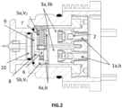
- Figure 2 discloses a delay unit comprising a piston chamber in which piston 6 is positioned in an initial idle position before firing.
- Figure 3 discloses a delay unit in which piston 6 has been displaced from its initial position.
- Figure 4 discloses a delay unit in which piston 6 has reached its end position.
- Figure 1 shows a delay unit 11 mounted in a round 12.
- the black strip 13 represents a short circuit which, subsequent to actuation and displacement of a subchamber piston 10, is broken after a predetermined period of time (the delay unit is dimensioned to result in a predetermined delay). By breaking the short circuit, arming for subsequent detonation of a warhead (not shown) may be initiated.
- An SAI (Safety/Arming/Initiation) unit 14 is arranged adjacent to the delay unit 11, i.e. behind the delay unit 11 in the firing direction.
- Illustrated lines 15 show the flow of combustion gases originating from combusted propellant (not shown on the left-hand side of the delay unit in figure 1 ). Combustion gases flow into the inlet channels 1a, 1b of the pressure chambers 3a, 3b of the delay unit 11 whereby a pressure is accumulated therein.
- Figure 2 shows a delay unit comprising two pressure chambers (3a, 3b) having predetermined volumes.
- the outlets from the pressure chambers (3a, 3b) may have a volume ranging from 0.1 to 50, preferably from 1 to 10, most preferably from 1 to 5 mm 3 .
- the area of the outlets from the pressure chambers (3a, 3b) may range from 1 to 10, preferably from 1 to 5, most preferably from 1 to 2 mm 2 .
- the length of the outlets from the pressure chambers (3a, 3b) may range from 1 to 10, preferably from 1 to 5, most preferably from 2 to 3 mm.
- combustion gases flow into inlet channels 1a, 1b whereby a pressure is accumulated in pressure chambers 3a, 3b whereby an overpressure is obtained in each of the pressure chambers 3a, 3b.
- back valves 2 in each of the channels 1a, 1b allow combustion gases to enter while safeguarding no combustion gases leak out via the inlet channels 1a, 1b.
- the chambers 3a, 3b are provided with outlet channels 4a, b through which combustion gases are transferred to a piston chamber divided into two compartments 5a and 5b by a piston 6 arranged in the piston chamber.
- the piston 6 has a first area facing the compartment 5a.
- the piston 6 has a second area facing a compartment 5b (below compartment 5a in figure 2 ).
- the piston 6 thus separates the piston chamber into two compartments.
- the spring 7 safeguards the piston is maintained in an initial idle position.
- an opening (outlet) is arranged between the piston chamber and a subchamber 9.
- piston 6 By maintaining the piston 6 in its initial idle position before any gas enters compartment 5b, piston 6 ensures there is no gas leaking out of the piston chamber via outlet channel 8 to the subchamber 9 provided with a subchamber piston 10.
- the piston 6 will be displaced from an initial idle position in figure 2 to an intermediate position as further shown in figure 3 .
- the piston 6 is displaced downstream such that the spring 7 is compressed.
- the arising pressure difference forces the piston 6 downstream by providing a higher pressure in compartment 5b than in compartment 5a. Hence, the piston 6 will be brought into motion due to the pressure difference.
- a low pressure difference for example a somewhat higher pressure in compartment 5b than 5a will result in a relatively slow motion of the piston 6 whereas a higher pressure difference imparts a quicker displacement of piston 6.
- the skilled person can design suitable areas of e.g. inlets 1a, 1b as well as outlets 4a, 4b to dimension the delay unit depending on the requirements and use thereof.
- the dimensioning of an evacuation hole may be used to establish a pressure difference in the pressure chambers which in turn may be used to establish a pressure difference in the piston chamber.
- Various parameters may be varied to provide a pressure difference over the piston 6 and thus control the delay unit 11.
- Provision of an evacuation channel (not shown) positioned on the same side as the inlet channel 1a is one option to reduce the accumulated pressure in pressure chamber 3a and eventually the pressure in compartments 5a and 5b to allow for displacement of piston 6 (upwards in figures 2-4 ).
- the evacuation channel may be designed with a diameter and length resulting in a suitable pressure difference in compartments 5a and 5b. The higher the pressure difference over the piston 6, the faster the displacement of the piston 6, and, the faster the combustion gases will flow into subchamber 9 as a consequence of the displacement of piston 6 unblocking opening 8.
- subchamber piston 10 As the opening 8 is unblocked, the combustion gases will flow into subchamber 9 and actuate subchamber piston 10 which is pressed to the left in the figures (cf. figures 3 and 4 ).
- subchamber piston 10 is maintained in an initial idle position prior to actuation thereof, e.g. by means of a resilient means such as a spring.
- a resilient means such as a spring.
- the subchamber piston As combustion gases enter the subchamber, the subchamber piston will be pressed downstream from its initial position to an end position in analogy with the piston 6 of the piston chamber.
- various mechanisms may be actuated, for example the breaking of a short circuit 13 as illustrated in figure 1 .
- Subchamber piston 10 may also control any other delay mechanism needed subsequent to firing of a projectile.
- FIG 3 shows an intermediate position of piston 6 displaced such that opening 8 of the outlet to subchamber 9 has become partially opened whereby combustion gases present in piston compartment 5b enters subchamber 9.
- the subchamber piston 10 will thus displace as shown in figure 3 wherein subchamber piston 10 divides the subchamber 9 into compartments 9a, 9b as shown in figure 3 .
- piston 6 and subchamber piston 10 have been further displaced to their respective end positions.
- Piston 6 has pressed the spring 7 to its end position whereby piston 6 has reached it end position.
- an actuation mechanism may be initiated such as the pressing of a copper bushing (initially positioned close to the subchamber wall) through the subchamber wall whereby a short circuit is broken resulting in arming of e.g. a fuze.
Landscapes
- Engineering & Computer Science (AREA)
- Chemical & Material Sciences (AREA)
- Combustion & Propulsion (AREA)
- General Engineering & Computer Science (AREA)
- Portable Nailing Machines And Staplers (AREA)
Claims (16)
- Verzögerungseinheit für ein Geschoss, umfassendi) eine erste und eine zweite Druckkammer (3a, 3b), die angeordnet sind, um Verbrennungsgase in einer Schusswaffe über mindestens einen Einlass (1a, 1b), der an jeder der ersten und der zweiten Druckkammer (3a, 3b) angeordnet ist, nach dem Zünden eines Geschosses aufzunehmen,ii) mindestens einen Auslass zum Übertragen der Verbrennungsgase (4a, 4b), die an jeder der ersten und der zweiten Druckkammer (3a, 3b) angeordnet sind, in eine Kolbenkammer, in der ein verschiebbarer Kolben (6) angeordnet ist, der die Kolbenkammer in einen ersten Raum (5b) mit einem Volumen V1 stromaufwärts des Kolbens (6) und einen zweiten Raum (5a) mit einem Volumen V2 stromabwärts des Kolbens (6) teilt, wobei die Auslässe (4a, 4b) von der ersten und der zweiten Druckkammer (3a, 3b) angeordnet sind, um die Verbrennungsgase zu den Räumen (5a, 5b) der Kolbenkammer zu übertragen, um eine Gesamtdruckdifferenz zwischen dem zweiten Raum (5a) und dem ersten Raum (5b) bereitzustellen, die den Kolben (6) in einer anfänglichen Ruheposition stromabwärts drückt, wodurch das Volumen V2 des zweiten Raums (5a) reduziert wird und wodurch der Kolben (6), der stromabwärts in Richtung einer Endposition gedrückt wird, eine Funktion zu einem vorbestimmten Zeitpunkt nach dem Zünden der Schusswaffe betätigt.
- Verzögerungseinheit nach Anspruch 1, wobei ein elastisches Mittel angeordnet ist, um den Kolben (6) vor einem Aufbauen einer Druckdifferenz zwischen den Räumen (5a, 5b) in einer anfänglichen Ruheposition unbeweglich zu halten.
- Verzögerungseinheit nach Anspruch 1 oder 2, wobei der Kolben (6) in der anfänglichen Ruheposition angeordnet ist, um einen Strom von Verbrennungsgasen aus der Kolbenkammer über eine Öffnung (8) zwischen der Kolbenkammer und einer Unterkammer (9) zu blockieren.
- Verzögerungseinheit nach Anspruch 3, wobei die Unterkammer (9) mit einem verschiebbaren Unterkammerkolben (10) versehen ist, der angeordnet ist, um aus einer anfänglichen Ruheposition verschoben zu werden, wenn er einem Strom von Verbrennungsgasen ausgesetzt ist, die aus der Kolbenkammer stammen.
- Verzögerungseinheit nach einem der Ansprüche 1 bis 4, wobei die Einlässe der ersten und der zweiten Druckkammer (3a, 3b) jeweils eine Fläche im Bereich von 0,1 bis 50 mm2 aufweisen.
- Verzögerungseinheit nach einem der Ansprüche 1 bis 5, wobei mindestens ein Auslass zu mindestens einer der ersten und/oder der zweiten Druckkammer (3a, 3b) angeordnet ist, um einen vorbestimmten Teil der Verbrennungsgase außerhalb der Verzögerungseinheit abzuführen.
- Verzögerungseinheit nach einem der Ansprüche 1 bis 6, wobei die Auslässe zum Übertragen von Verbrennungsgasen (4a, 4b) in die Kolbenkammer an der gegenüberliegenden Seite der Druckkammern relativ zu den Einlässen (1a, 1b) angeordnet sind.
- Verzögerungseinheit nach einem der Ansprüche 1 bis 7, wobei der Kolben (6) angeordnet ist, um von einer anfänglichen Ruheposition stromabwärts zu einer Endposition verschoben zu werden, sodass eine Öffnung (8) zwischen der Kolbenkammer und einer Unterkammer (9) freigegeben wird.
- Verzögerungseinheit nach Anspruch 8, wobei ein Unterkammerkolben (10) angeordnet ist, um einen Kurzschluss zu unterbrechen, umfassend einen piezoelektrischen Sensor nach Betätigung des Unterkammerkolbens (10), wobei der Unterkammerkolben (10) angeordnet ist, um durch die Verbrennungsgase betätigt zu werden, die in die Unterkammer strömen, wenn die Öffnung (8) freigegeben wird, wobei, wenn die Verbrennungsgase in die Unterkammer eintreten, der Unterkammerkolben angeordnet ist, um stromabwärts von seiner Ausgangsposition zu einer Endposition in Analogie zu dem Kolben (6) der Kolbenkammer gedrückt zu werden.
- Verzögerungseinheit nach Anspruch 6, wobei der Auslass zum Abführen von Verbrennungsgasen eine Länge im Bereich von 1 bis 50 mm aufweist.
- Verzögerungseinheit nach einem der Ansprüche 1 bis 10, wobei der Auslass jeder Druckkammer (4a, 4b) zum Übertragen von Verbrennungsgasen eine Fläche im Bereich von 0,5 bis 50 mm2 aufweist.
- Verzögerungseinheit nach einem der Ansprüche 1 bis 11, wobei eine Sicherung mit der Verzögerungseinheit verbunden ist.
- Verzögerungseinheit nach Anspruch 1, wobei ein piezoelektrischer Sensor mit der Verzögerungseinheit verbunden ist.
- Verzögerungseinheit nach Anspruch 9, wobei der piezoelektrische Sensor ein piezoelektrischer Kristall ist.
- Verfahren zum Verzögern eines Mechanismus für ein Geschoss in einer Schusswaffe, umfassend eine Verzögerungseinheit nach einem der Ansprüche 1 bis 14, umfassend die folgenden Schritte:i) Aufnehmen von Verbrennungsgasen durch eine erste und eine zweite Druckkammer (3a, 3b) in einer Schusswaffe über mindestens einen Einlass (1a, 1b), der an jeder der ersten und der zweiten Druckkammer (3a, 3b) angeordnet ist, nach dem Zünden eines Geschosses undii) Übertragen der Verbrennungsgase (4a, 4b) durch mindestens einen Auslass, wobei der mindestens eine Auslass an jeder der ersten und der zweiten Druckkammer (3a, 3b) angeordnet ist, in eine Kolbenkammer, in der ein verschiebbarer Kolben (6) angeordnet ist, der die Kolbenkammer in einen ersten Raum (5b) mit einem Volumen V1 stromaufwärts des Kolbens (6) und einen zweiten Raum (5a) mit einem Volumen V2 stromabwärts des Kolbens (6) teilt, wobei die Auslässe (4a, 4b) von der ersten und der zweiten Druckkammer (3a, 3b) angeordnet sind, um die Verbrennungsgase zu den Räumen (5a, 5b) der Kolbenkammer zu übertragen, um eine Gesamtdruckdifferenz zwischen dem zweiten Raum (5a) und dem ersten Raum (5b) bereitzustellen, die den Kolben (6) in einer anfänglichen Ruheposition stromabwärts drückt, wodurch das Volumen V2 des zweiten Raums (5a) reduziert wird und wodurch der Kolben (6), der stromabwärts in Richtung einer Endposition gedrückt wird, eine Funktion zu einem vorbestimmten Zeitpunkt nach dem Zünden der Schusswaffe betätigt.
- Verwendung einer Verzögerungseinheit nach einem der Ansprüche 1 bis 14 zum Verzögern einer vorzeitigen Detonation eines Sprengkopfes.
Applications Claiming Priority (2)
| Application Number | Priority Date | Filing Date | Title |
|---|---|---|---|
| SE1800241A SE543078C2 (en) | 2018-12-14 | 2018-12-14 | Delay unit and method for a projectile |
| PCT/SE2019/051272 WO2020122803A1 (en) | 2018-12-14 | 2019-12-12 | Delay unit for a projectile |
Publications (4)
| Publication Number | Publication Date |
|---|---|
| EP3894781A1 EP3894781A1 (de) | 2021-10-20 |
| EP3894781A4 EP3894781A4 (de) | 2022-08-17 |
| EP3894781C0 EP3894781C0 (de) | 2025-06-18 |
| EP3894781B1 true EP3894781B1 (de) | 2025-06-18 |
Family
ID=71076891
Family Applications (1)
| Application Number | Title | Priority Date | Filing Date |
|---|---|---|---|
| EP19895653.4A Active EP3894781B1 (de) | 2018-12-14 | 2019-12-12 | Verzögerungseinheit für ein geschoss |
Country Status (5)
| Country | Link |
|---|---|
| US (1) | US11598619B2 (de) |
| EP (1) | EP3894781B1 (de) |
| ES (1) | ES3035920T3 (de) |
| SE (1) | SE543078C2 (de) |
| WO (1) | WO2020122803A1 (de) |
Families Citing this family (1)
| Publication number | Priority date | Publication date | Assignee | Title |
|---|---|---|---|---|
| SE543078C2 (en) * | 2018-12-14 | 2020-10-06 | Saab Ab | Delay unit and method for a projectile |
Family Cites Families (9)
| Publication number | Priority date | Publication date | Assignee | Title |
|---|---|---|---|---|
| US682728A (en) * | 1900-11-15 | 1901-09-17 | Michael A Lynch | Percussion-fuse for explosive projectiles. |
| US2674946A (en) | 1950-06-14 | 1954-04-13 | Bofors Ab | Control device for an electric circuit |
| US2918870A (en) * | 1958-04-21 | 1959-12-29 | Meister Jack | Fuze pressure arming |
| US2926609A (en) * | 1958-05-28 | 1960-03-01 | Henry R Van Goey | Gas operated safety and arming mechanism |
| US3229638A (en) * | 1964-07-31 | 1966-01-18 | Lionel L Woolston | Air-launch environmental safing device |
| DE3421572C2 (de) * | 1984-06-09 | 1986-10-02 | Messerschmitt-Bölkow-Blohm GmbH, 8012 Ottobrunn | Sicherungseinrichtung für Zünder von Kleinraketengefechtsköpfen |
| SE463788B (sv) * | 1989-11-21 | 1991-01-21 | Saab Missiles Ab | Projektil foer spridning av en last i form av en pyroteknisk laddning |
| SE463580B (sv) | 1989-11-21 | 1990-12-10 | Saab Missiles Ab | Projektil foer spridning av en last med tidsfoerdroejning |
| SE543078C2 (en) * | 2018-12-14 | 2020-10-06 | Saab Ab | Delay unit and method for a projectile |
-
2018
- 2018-12-14 SE SE1800241A patent/SE543078C2/en unknown
-
2019
- 2019-12-12 US US17/312,586 patent/US11598619B2/en active Active
- 2019-12-12 WO PCT/SE2019/051272 patent/WO2020122803A1/en not_active Ceased
- 2019-12-12 EP EP19895653.4A patent/EP3894781B1/de active Active
- 2019-12-12 ES ES19895653T patent/ES3035920T3/es active Active
Also Published As
| Publication number | Publication date |
|---|---|
| US20210356244A1 (en) | 2021-11-18 |
| SE543078C2 (en) | 2020-10-06 |
| EP3894781A4 (de) | 2022-08-17 |
| EP3894781C0 (de) | 2025-06-18 |
| EP3894781A1 (de) | 2021-10-20 |
| ES3035920T3 (en) | 2025-09-11 |
| SE1800241A1 (en) | 2020-06-15 |
| WO2020122803A1 (en) | 2020-06-18 |
| US11598619B2 (en) | 2023-03-07 |
Similar Documents
| Publication | Publication Date | Title |
|---|---|---|
| EP2856067B2 (de) | Druckentlastungssystem für hülsenmunition | |
| KR100619578B1 (ko) | 소형화기용 총신조립체 및 소형화기용 총신조립체로부터의 탄환발사방법 | |
| US20090241795A1 (en) | Projectiles with sealed propellant | |
| US1416828A (en) | Firearm | |
| US3944168A (en) | Artillery projectile with spreading tail assembly | |
| CN111622863A (zh) | 一种小型固体火箭发动机推力终止装置 | |
| US5481978A (en) | Cartridge case | |
| EP3894781B1 (de) | Verzögerungseinheit für ein geschoss | |
| EP2690390B1 (de) | Vorrichtung für unterwasserschüsse aus einer feuerwaffe | |
| US5419118A (en) | Multi-stage rocket motors | |
| US6578488B2 (en) | Safety device for a pyrotechnic impact fuse of a ballistic high explosive shell | |
| US4005632A (en) | Liquid propellant gun | |
| US3434419A (en) | Rocket assisted projectile with movable piston base plate | |
| US8141492B1 (en) | Insulated secondary charges | |
| CN109990651A (zh) | 用于多弹串联发射火炮的前置喷管式电磁式减后坐装置 | |
| US3830158A (en) | Initiator assembly | |
| US3861310A (en) | Zero volume rocket ignition system | |
| CN109990655A (zh) | 用于多弹串联发射火炮的前置喷管式气动式减后坐装置 | |
| RU2766018C1 (ru) | Способ производства выстрела из автоматического безгильзового оружия и устройство для его осуществления | |
| US3583320A (en) | Safety projectile for underwater detonation | |
| US2953094A (en) | Pneumatic timer | |
| EP2872850A1 (de) | Granate, insbesondere 40-mm-granate | |
| RU2212017C1 (ru) | Устройство парашютирования противоградовой ракеты | |
| RU2747020C1 (ru) | Морской сигнальный боеприпас | |
| CN118602857A (zh) | 一种低过载活塞式高低压作动装置 |
Legal Events
| Date | Code | Title | Description |
|---|---|---|---|
| STAA | Information on the status of an ep patent application or granted ep patent |
Free format text: STATUS: THE INTERNATIONAL PUBLICATION HAS BEEN MADE |
|
| PUAI | Public reference made under article 153(3) epc to a published international application that has entered the european phase |
Free format text: ORIGINAL CODE: 0009012 |
|
| STAA | Information on the status of an ep patent application or granted ep patent |
Free format text: STATUS: REQUEST FOR EXAMINATION WAS MADE |
|
| 17P | Request for examination filed |
Effective date: 20210616 |
|
| AK | Designated contracting states |
Kind code of ref document: A1 Designated state(s): AL AT BE BG CH CY CZ DE DK EE ES FI FR GB GR HR HU IE IS IT LI LT LU LV MC MK MT NL NO PL PT RO RS SE SI SK SM TR |
|
| DAV | Request for validation of the european patent (deleted) | ||
| DAX | Request for extension of the european patent (deleted) | ||
| A4 | Supplementary search report drawn up and despatched |
Effective date: 20220720 |
|
| RIC1 | Information provided on ipc code assigned before grant |
Ipc: F42C 15/00 20060101ALN20220714BHEP Ipc: F42C 11/02 20060101ALN20220714BHEP Ipc: F42C 15/30 20060101AFI20220714BHEP |
|
| GRAP | Despatch of communication of intention to grant a patent |
Free format text: ORIGINAL CODE: EPIDOSNIGR1 |
|
| STAA | Information on the status of an ep patent application or granted ep patent |
Free format text: STATUS: GRANT OF PATENT IS INTENDED |
|
| RIC1 | Information provided on ipc code assigned before grant |
Ipc: F42C 15/00 20060101ALN20250205BHEP Ipc: F42C 11/02 20060101ALN20250205BHEP Ipc: F42C 15/30 20060101AFI20250205BHEP |
|
| INTG | Intention to grant announced |
Effective date: 20250217 |
|
| GRAS | Grant fee paid |
Free format text: ORIGINAL CODE: EPIDOSNIGR3 |
|
| GRAA | (expected) grant |
Free format text: ORIGINAL CODE: 0009210 |
|
| STAA | Information on the status of an ep patent application or granted ep patent |
Free format text: STATUS: THE PATENT HAS BEEN GRANTED |
|
| AK | Designated contracting states |
Kind code of ref document: B1 Designated state(s): AL AT BE BG CH CY CZ DE DK EE ES FI FR GB GR HR HU IE IS IT LI LT LU LV MC MK MT NL NO PL PT RO RS SE SI SK SM TR |
|
| REG | Reference to a national code |
Ref country code: GB Ref legal event code: FG4D |
|
| REG | Reference to a national code |
Ref country code: CH Ref legal event code: EP |
|
| REG | Reference to a national code |
Ref country code: DE Ref legal event code: R096 Ref document number: 602019071395 Country of ref document: DE |
|
| REG | Reference to a national code |
Ref country code: CH Ref legal event code: EP |
|
| REG | Reference to a national code |
Ref country code: IE Ref legal event code: FG4D |
|
| U01 | Request for unitary effect filed |
Effective date: 20250708 |
|
| U07 | Unitary effect registered |
Designated state(s): AT BE BG DE DK EE FI FR IT LT LU LV MT NL PT RO SE SI Effective date: 20250714 |
|
| REG | Reference to a national code |
Ref country code: ES Ref legal event code: FG2A Ref document number: 3035920 Country of ref document: ES Kind code of ref document: T3 Effective date: 20250911 |
|
| PG25 | Lapsed in a contracting state [announced via postgrant information from national office to epo] |
Ref country code: GR Free format text: LAPSE BECAUSE OF FAILURE TO SUBMIT A TRANSLATION OF THE DESCRIPTION OR TO PAY THE FEE WITHIN THE PRESCRIBED TIME-LIMIT Effective date: 20250919 |
|
| PG25 | Lapsed in a contracting state [announced via postgrant information from national office to epo] |
Ref country code: HR Free format text: LAPSE BECAUSE OF FAILURE TO SUBMIT A TRANSLATION OF THE DESCRIPTION OR TO PAY THE FEE WITHIN THE PRESCRIBED TIME-LIMIT Effective date: 20250618 |
|
| PG25 | Lapsed in a contracting state [announced via postgrant information from national office to epo] |
Ref country code: RS Free format text: LAPSE BECAUSE OF FAILURE TO SUBMIT A TRANSLATION OF THE DESCRIPTION OR TO PAY THE FEE WITHIN THE PRESCRIBED TIME-LIMIT Effective date: 20250918 |
|
| U20 | Renewal fee for the european patent with unitary effect paid |
Year of fee payment: 7 Effective date: 20251022 |