EP3894655B1 - Cutter head arrangement - Google Patents
Cutter head arrangement Download PDFInfo
- Publication number
- EP3894655B1 EP3894655B1 EP19897173.1A EP19897173A EP3894655B1 EP 3894655 B1 EP3894655 B1 EP 3894655B1 EP 19897173 A EP19897173 A EP 19897173A EP 3894655 B1 EP3894655 B1 EP 3894655B1
- Authority
- EP
- European Patent Office
- Prior art keywords
- cutter head
- side wall
- head side
- arrangement
- cutter
- Prior art date
- Legal status (The legal status is an assumption and is not a legal conclusion. Google has not performed a legal analysis and makes no representation as to the accuracy of the status listed.)
- Active
Links
Images


Classifications
-
- E—FIXED CONSTRUCTIONS
- E21—EARTH OR ROCK DRILLING; MINING
- E21B—EARTH OR ROCK DRILLING; OBTAINING OIL, GAS, WATER, SOLUBLE OR MELTABLE MATERIALS OR A SLURRY OF MINERALS FROM WELLS
- E21B10/00—Drill bits
- E21B10/08—Roller bits
- E21B10/12—Roller bits with discs cutters
-
- E—FIXED CONSTRUCTIONS
- E21—EARTH OR ROCK DRILLING; MINING
- E21B—EARTH OR ROCK DRILLING; OBTAINING OIL, GAS, WATER, SOLUBLE OR MELTABLE MATERIALS OR A SLURRY OF MINERALS FROM WELLS
- E21B10/00—Drill bits
- E21B10/26—Drill bits with leading portion, i.e. drill bits with a pilot cutter; Drill bits for enlarging the borehole, e.g. reamers
- E21B10/265—Bi-center drill bits, i.e. an integral bit and eccentric reamer used to simultaneously drill and underream the hole
-
- E—FIXED CONSTRUCTIONS
- E21—EARTH OR ROCK DRILLING; MINING
- E21B—EARTH OR ROCK DRILLING; OBTAINING OIL, GAS, WATER, SOLUBLE OR MELTABLE MATERIALS OR A SLURRY OF MINERALS FROM WELLS
- E21B10/00—Drill bits
- E21B10/26—Drill bits with leading portion, i.e. drill bits with a pilot cutter; Drill bits for enlarging the borehole, e.g. reamers
- E21B10/28—Drill bits with leading portion, i.e. drill bits with a pilot cutter; Drill bits for enlarging the borehole, e.g. reamers with non-expansible roller cutters
-
- E—FIXED CONSTRUCTIONS
- E21—EARTH OR ROCK DRILLING; MINING
- E21B—EARTH OR ROCK DRILLING; OBTAINING OIL, GAS, WATER, SOLUBLE OR MELTABLE MATERIALS OR A SLURRY OF MINERALS FROM WELLS
- E21B10/00—Drill bits
- E21B10/62—Drill bits characterised by parts, e.g. cutting elements, which are detachable or adjustable
- E21B10/627—Drill bits characterised by parts, e.g. cutting elements, which are detachable or adjustable with plural detachable cutting elements
-
- E—FIXED CONSTRUCTIONS
- E21—EARTH OR ROCK DRILLING; MINING
- E21B—EARTH OR ROCK DRILLING; OBTAINING OIL, GAS, WATER, SOLUBLE OR MELTABLE MATERIALS OR A SLURRY OF MINERALS FROM WELLS
- E21B27/00—Containers for collecting or depositing substances in boreholes or wells, e.g. bailers, baskets or buckets for collecting mud or sand; Drill bits with means for collecting substances, e.g. valve drill bits
- E21B27/005—Collecting means with a strainer
-
- E—FIXED CONSTRUCTIONS
- E21—EARTH OR ROCK DRILLING; MINING
- E21D—SHAFTS; TUNNELS; GALLERIES; LARGE UNDERGROUND CHAMBERS
- E21D1/00—Sinking shafts
- E21D1/03—Sinking shafts mechanically, e.g. by loading shovels or loading buckets, scraping devices, conveying screws
- E21D1/06—Sinking shafts mechanically, e.g. by loading shovels or loading buckets, scraping devices, conveying screws with shaft-boring cutters
-
- E—FIXED CONSTRUCTIONS
- E21—EARTH OR ROCK DRILLING; MINING
- E21B—EARTH OR ROCK DRILLING; OBTAINING OIL, GAS, WATER, SOLUBLE OR MELTABLE MATERIALS OR A SLURRY OF MINERALS FROM WELLS
- E21B7/00—Special methods or apparatus for drilling
- E21B7/28—Enlarging drilled holes, e.g. by counterboring
-
- E—FIXED CONSTRUCTIONS
- E21—EARTH OR ROCK DRILLING; MINING
- E21D—SHAFTS; TUNNELS; GALLERIES; LARGE UNDERGROUND CHAMBERS
- E21D9/00—Tunnels or galleries, with or without linings; Methods or apparatus for making thereof; Layout of tunnels or galleries
- E21D9/10—Making by using boring or cutting machines
- E21D9/11—Making by using boring or cutting machines with a rotary drilling-head cutting simultaneously the whole cross-section, i.e. full-face machines
- E21D9/112—Making by using boring or cutting machines with a rotary drilling-head cutting simultaneously the whole cross-section, i.e. full-face machines by means of one single rotary head or of concentric rotary heads
Definitions
- JP2017-128843 discloses a cylindrical tunnel excavator having a cutter face on the front end of a main body portion.
- the objective of this invention is to provide a tunnel excavator capable of excavating the ground efficiently by making the shear stress of the cutter face uniform or close thereto.
- the front cutter face is formed in a conical shape whose centre is recessed rearward, so that the shear stress generated on the inner peripheral surface of the inverted conical cutter face has a constant value, regardless of the radial position along the cutter face.
- US3379264 discloses an earth boring machine having a plurality of cutting disks having wedge form peripheries, which are moved while being held against the working face under great pressure in concentric paths over the working face.
- the cutting disks are axially located on a cutter head in different planes so that the working face is of a cone-like configuration with the conical surfaces being desirably quite steep.
- Each cutter disk follows in succession the cut made by the next cutter inwardly and downwardly and works to break away an area which has lost its lateral support on the downhill side by the action of the cutter ahead, which is one increment inwardly and downwardly toward the center.
- CN-A-102400647 discloses a drill bit comprising a disc-shaped cutter disc, the lower part of the cutter disc having a concave cavity, wherein cutting teeth are arranged on the inner wall of the cavity, and wherein the central axis of the cavity coincides with the central axis of the cutter disc.
- the conical body of the recessed wall portion defines a conical recess (proximate a central region of the cutter head portion, at a distal end of the cutter head portion).
- the conical body accordingly defines an inwardly extending apex that terminates substantially in line with a central axis of the cutter head portion.
- the cutter elements may be arranged concentrically and/or radially on the conical body
- the cutter head side wall is substantially cylindrical and the cutter head portion includes a tapering peripheral wall that extends between (the distal end of) the cutter head side wall and the rim portion, with the rim portion accordingly protruding from the cutter head side wall, so that the rim portion defines a circular rim portion.
- the tapering peripheral wall may also be fitted with cutter elements.
- the cutter elements may be installed and replaced either from the front or the rear of (i.e. from within the chamber of) the cutter head portion.
- the cutter head arrangement comprises a connector portion extending from (a proximal end of) the cutter head side wall to enable the cutter head arrangement to be secured to a boring machine, such as a blind shaft boring machine, if required.
- a boring machine such as a blind shaft boring machine
- the cutter head arrangement is part of a larger boring machine.
- the cutter head arrangement can be used on its own without the need for it to be connected to a boring machine.
- the size of the cutter head portion can also change according to requirements and is not limited to any particular size.
- the cutter head arrangement 10 defines a pilot shaft cutter head of the shaft boring machine 50.
- a pilot shaft main drive 52 is provided to rotatingly drive the cutter head arrangement 10 relative to the boring machine 50.
- the shaft boring machine 50 is part of a larger shaft boring system 54, of the type disclosed in WO2016/116910 and WO2018/055549 .
- the shaft boring machine 50 includes a reamer cutter head 56 driven by a reamer main drive 58 to ream the main, enlarged shaft.
- the cutter head arrangement 10 extends from the lowermost end of the shaft boring machine 50 to blind bore a pilot hole, in use.
- the size of the cutter head arrangement 10 can also change according to requirements and is not limited to any particular size.
- the connector portion 12 includes a substantially cylindrical connector head side wall 17 extending from the cutter head side wall 15.
- An end wall 18 extends across a proximal end of the connector head side wall 17, the end wall 18 defining a substantially central connector aperture 19 therein to facilitate the fitting of the cutter head arrangement 10 to the boring machine 50.
- the front cutter head portion 14 includes a substantially circular rim portion 22 extending from a distal end of the cutter head side wall 15.
- the rim portion 22 defines a working, contact face of the front cutter head portion 14.
- the conical body 24 thus defines a conical recess 25 proximate a central region of the cutter head portion 14, at a distal end of the cutter head portion 14, with the conical body 24 extending inwardly towards the interface 26 between the rear connector portion 12 and the front cutter head portion 14.
- the conical body 24 accordingly defines an inwardly extending apex 28 that terminates substantially in line with a central axis 30 of the cutter head arrangement 10.
- the cutter head portion 14 includes a tapering peripheral wall 32 that extends between the distal end of the cutter head side wall 15 and the rim portion 22.
- the rim portion 22 accordingly protrudes from the cutter head side wall 15, so that the rim portion 22 defines a circular ridge between the inwardly extending conical body 24 and the tapering peripheral wall 32.
- a plurality of concentric and/or radial cutter elements 38, 40, 42 are fitted on or proximate the rim portion 22 and/or the inwardly extending conical portion 24 and/or the tapering peripheral wall 32, respectively, to enable the cutter head portion 14 to blind bore a pilot hole, in use.
- the cutter elements 38, 40, 42 can be installed either from the back of the cutter head portion 14 (i.e. from within the chamber or cavity 16) or from the front.
- the cutter elements 38, 40, 42 are typically closed off with a cover element.
- This cover element can have an electronic device to measure certain parameters for example the wear of the cutter element 38, 40, 42 and the working temperature.
- a rotary swivel that is used in the cutter head portion 14 can be used to supply the cutter head portion 14 with required fluids for example but not limited to hydraulic fluid, water and cables that can be used for intelligence and or communication.
- the rim portion 22 defines at least one material handling aperture 44 to accommodate a pilot shaft material handling arrangement 80, which will be described in more detail further below, with reference to Figures 9 and 10 .
- the at least one material handling aperture 44 extends between the contact face of the rim portion 22 and the chamber 16 surrounded by the cutter head side wall 15.
- the distance from the cutter head portion 14 to the cutting face is spaced to ensure that the material that is being cut/bored is of a predetermined size.
- This spacing together with the spacing of the cutter elements 38, 40, 42 and the number of cutter elements 38, 40, 42, is used to predetermine the size of particle/material cuttings.
- This combination of factors acts as a sizing guide or arrangement to enable the particle or material size to be controlled, to ultimately ensure that a suction pipe 82 (described further below) does not become blocked by overly sized particles.
- a cutter element can be installed in front of the material handling aperture 44 to ensure that the material that is handled through the aperture 44 is an appropriate size to prevent blockages.
- scraper elements can be fitted to the cutter head portion 14 to encourage movement of cuttings to the material handling aperture/s 44.
- the scraper elements can be replaced as needed.
- the pilot shaft material handling arrangement 80 comprises a cutter head suction pipe 82 extending from the material handling aperture 44.
- the cutter head suction pipe 82 extends adjacent an inner face of the conical body 24 and then upwardly along the central axis of the cutter head portion 14. The end of the cutter head suction pipe 82 protrudes from the central connector aperture 19 of the connector portion 12.
- the end of the cutter head suction pipe 82 is fitted with a double walled swivel arrangement 84 that defines a first pipe 86 that is in communication with the cutter head suction pipe 82 and a second pipe 88 that leads into a cutter head blower pipe 90 that extends up to a vacuum unit 92 provided on an upper working stage of the shaft boring system 54, as shown in Figure 8 .
- the pilot shaft material handling arrangement 80 further comprises a kibble 94 that acts as a vacuum collector kibble that can be lowered through the shaft boring machine 50 and secured to the double walled swivel arrangement 84.
- the kibble 94 includes a kibble suction pipe 96 that is secured to the other end of the first pipe 86 of the double walled swivel arrangement 84 so as to be in material communication with the cutter head suction pipe 82.
- the swivel arrangement 84 allows material to be sucked away from the pilot hole being bored as the cutter head arrangement 10 rotates, via the cutter head suction pipe 82, as indicated by arrows 98 in Figure 9 .
- the material 100 accumulates within the relatively stationary kibble 94 via the kibble suction pipe 96, via the double walled swivel arrangement 84, as the cutter head arrangement 10 continues to rotate.
Landscapes
- Engineering & Computer Science (AREA)
- Mining & Mineral Resources (AREA)
- Life Sciences & Earth Sciences (AREA)
- Geology (AREA)
- General Life Sciences & Earth Sciences (AREA)
- Geochemistry & Mineralogy (AREA)
- Environmental & Geological Engineering (AREA)
- Fluid Mechanics (AREA)
- Physics & Mathematics (AREA)
- Mechanical Engineering (AREA)
- Processing Of Stones Or Stones Resemblance Materials (AREA)
- Excavating Of Shafts Or Tunnels (AREA)
- Auxiliary Devices For Machine Tools (AREA)
- Drilling Tools (AREA)
- Milling Processes (AREA)
- Earth Drilling (AREA)
Description
- THIS invention relates to a cutter head arrangement, typically for use in the mining or civil industries. In one version, the cutter head arrangement may be fitted to a shaft boring machine for blind shaft boring and enlargement applications, such as production and ventilation shafts. However, the applications of the cutter head arrangement are numerous and may ultimately be used wherever a shaft/hole is required.
-
JP2017-128843 -
US3379264 _discloses an earth boring machine having a plurality of cutting disks having wedge form peripheries, which are moved while being held against the working face under great pressure in concentric paths over the working face. The cutting disks are axially located on a cutter head in different planes so that the working face is of a cone-like configuration with the conical surfaces being desirably quite steep. Each cutter disk follows in succession the cut made by the next cutter inwardly and downwardly and works to break away an area which has lost its lateral support on the downhill side by the action of the cutter ahead, which is one increment inwardly and downwardly toward the center. -
CN-A-102400647 discloses a drill bit comprising a disc-shaped cutter disc, the lower part of the cutter disc having a concave cavity, wherein cutting teeth are arranged on the inner wall of the cavity, and wherein the central axis of the cavity coincides with the central axis of the cutter disc. - According to the invention there is provided a cutter head arrangement for a shaft boring machine as defined in
claim 1. - According to
claim 1, the conical body of the recessed wall portion defines a conical recess (proximate a central region of the cutter head portion, at a distal end of the cutter head portion). The conical body accordingly defines an inwardly extending apex that terminates substantially in line with a central axis of the cutter head portion. - In an embodiment, the cutter elements may be arranged concentrically and/or radially on the conical body
In an embodiment, the cutter head side wall is substantially cylindrical and the cutter head portion includes a tapering peripheral wall that extends between (the distal end of) the cutter head side wall and the rim portion, with the rim portion accordingly protruding from the cutter head side wall, so that the rim portion defines a circular rim portion. In an embodiment, the tapering peripheral wall may also be fitted with cutter elements. - Advantageously, the cutter elements may be installed and replaced either from the front or the rear of (i.e. from within the chamber of) the cutter head portion.
- In an embodiment, the cutter head arrangement comprises a connector portion extending from (a proximal end of) the cutter head side wall to enable the cutter head arrangement to be secured to a boring machine, such as a blind shaft boring machine, if required. Thus, in one version, the cutter head arrangement is part of a larger boring machine. However, in another version, the cutter head arrangement can be used on its own without the need for it to be connected to a boring machine. The size of the cutter head portion can also change according to requirements and is not limited to any particular size.
- The connector portion includes a (substantially cylindrical) connector head side wall extending from the cutter head side wall, with an end wall extending across a (proximal) end of the connector head side wall, the end wall defining a substantially central connector aperture therein.
- In an embodiment, the cutter head side wall is enlarged relative to the connector head side wall, with a step accordingly being defined between the cutter head side wall and the connector head side wall.
- In an embodiment, the cutter elements are fitted on or proximate the rim portion and the inwardly extending conical body and the tapering peripheral wall.
- Advantageously, the distance from the cutter head portion to the cutting face is spaced to ensure that the material that is being cut/bored is of a predetermined size. This spacing, together with the spacing of the cutter elements and the number of cutter elements, is used to predetermine the size of particle/material cuttings. This combination of factors acts as a sizing guide or arrangement to enable the particle or material size to be controlled, to ultimately ensure that the cutter head suction pipe does not become blocked by overly sized particles.
- In an embodiment, a cutter element is provided in front of the material handling aperture to ensure that the material that moves through the material handling aperture is an appropriate size to prevent blockages.
- In an embodiment, the conical body of the recessed wall portion extends away from the rim portion at an angle of 35° into the chamber.
- In an embodiment, scraper elements can be fitted to the cutter head portion to encourage movement of cuttings to the material handling aperture/s. The scraper elements can be replaced as needed.
- The invention will now be further described, by way of example, with reference to the accompanying diagrammatic drawings.
- In the drawings:
- Figure 1
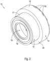
- shows a front perspective view of a cutter head arrangement, according to the invention;
- Figure 2
- shows a rear perspective view of the cutter head arrangement;
- Figure 3
- shows a front view of the cutter head arrangement;
- Figure 4
- shows a side view of the cutter head arrangement;
- Figure 5
- shows a rear view of the cutter head arrangement;
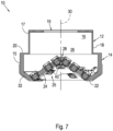
- Figures 6 and 7
- show various cross-sectional side views of the cutter head arrangement;
- Figure 8
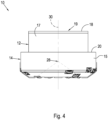
- shows the cutter head arrangement in relation to a boring machine, to which the cutter head arrangement may be secured in one application/version of the invention; and
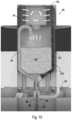
- Figures 9 and 10
- show a pilot shaft material handling arrangement according, at two different stages of the material handling procedure.
- Referring first to
Figures 1 to 8 , acutter head arrangement 10 according to one version/application of the invention is shown. In this version/application, thecutter head arrangement 10 comprises arear connector portion 12 to enable thecutter head arrangement 10 to be secured to a boring machine 50 (shown inFigure 8 ), such as a blind shaft boring machine. Thus, in one version, thecutter head arrangement 10 is part of a largerboring machine 50. However, in another version, thecutter head arrangement 10 can be used on its own, as an individual piece of equipment, without the need for it to be connected to a boring machine. - The
cutter head arrangement 10 defines a pilot shaft cutter head of theshaft boring machine 50. A pilot shaftmain drive 52 is provided to rotatingly drive thecutter head arrangement 10 relative to theboring machine 50. In one application, as shown inFigure 8 , theshaft boring machine 50 is part of a largershaft boring system 54, of the type disclosed inWO2016/116910 andWO2018/055549 . Theshaft boring machine 50 includes areamer cutter head 56 driven by a reamermain drive 58 to ream the main, enlarged shaft. Thecutter head arrangement 10 extends from the lowermost end of theshaft boring machine 50 to blind bore a pilot hole, in use. - The size of the
cutter head arrangement 10 can also change according to requirements and is not limited to any particular size. - A front
cutter head portion 14 extends from therear connector portion 12. Thecutter head portion 14 includes a substantially cylindrical cutterhead side wall 15 to define a chamber orcavity 16, as best shown inFigures 6 and7 , surrounded by the cutterhead side wall 15. Theconnector portion 12 extends from a proximal end of the cutterhead side wall 15. - The
connector portion 12 includes a substantially cylindrical connectorhead side wall 17 extending from the cutterhead side wall 15. Anend wall 18 extends across a proximal end of the connectorhead side wall 17, theend wall 18 defining a substantiallycentral connector aperture 19 therein to facilitate the fitting of thecutter head arrangement 10 to theboring machine 50. - In an embodiment, the cutter
head side wall 15 is enlarged relative to the connectorhead side wall 17, with astep 20 accordingly being defined between the cutterhead side wall 15 and the connectorhead side wall 17. - The front
cutter head portion 14 includes a substantiallycircular rim portion 22 extending from a distal end of the cutterhead side wall 15. Therim portion 22 defines a working, contact face of the frontcutter head portion 14. - A recessed
wall portion 24, typically in the form of aconical body 24, extends away from therim portion 22 inwardly (at an angle of 35°, for example, as best shown inFigure 7 ) into thechamber 16 so as to be surrounded by the cutterhead side wall 15. Theconical body 24 thus defines aconical recess 25 proximate a central region of thecutter head portion 14, at a distal end of thecutter head portion 14, with theconical body 24 extending inwardly towards theinterface 26 between therear connector portion 12 and the frontcutter head portion 14. - As best shown in
Figures 6 and7 , theconical body 24 accordingly defines an inwardly extendingapex 28 that terminates substantially in line with acentral axis 30 of thecutter head arrangement 10. - In an embodiment, the
cutter head portion 14 includes a taperingperipheral wall 32 that extends between the distal end of the cutterhead side wall 15 and therim portion 22. Therim portion 22 accordingly protrudes from the cutterhead side wall 15, so that therim portion 22 defines a circular ridge between the inwardly extendingconical body 24 and the taperingperipheral wall 32. - In an embodiment, a plurality of concentric and/or
radial cutter elements rim portion 22 and/or the inwardly extendingconical portion 24 and/or the taperingperipheral wall 32, respectively, to enable thecutter head portion 14 to blind bore a pilot hole, in use. - The
cutter elements cutter elements cutter element cutter head portion 14 can be used to supply thecutter head portion 14 with required fluids for example but not limited to hydraulic fluid, water and cables that can be used for intelligence and or communication. - The
rim portion 22 defines at least onematerial handling aperture 44 to accommodate a pilot shaftmaterial handling arrangement 80, which will be described in more detail further below, with reference toFigures 9 and10 . As best shown inFigures 7 and8 , the at least onematerial handling aperture 44 extends between the contact face of therim portion 22 and thechamber 16 surrounded by the cutterhead side wall 15. - Advantageously, the distance from the
cutter head portion 14 to the cutting face is spaced to ensure that the material that is being cut/bored is of a predetermined size. This spacing, together with the spacing of thecutter elements cutter elements material handling aperture 44 to ensure that the material that is handled through theaperture 44 is an appropriate size to prevent blockages. - In an embodiment, scraper elements can be fitted to the
cutter head portion 14 to encourage movement of cuttings to the material handling aperture/s 44. The scraper elements can be replaced as needed. - Turning now to
Figures 9 and10 , the pilot shaftmaterial handling arrangement 80 comprises a cutterhead suction pipe 82 extending from thematerial handling aperture 44. The cutterhead suction pipe 82 extends adjacent an inner face of theconical body 24 and then upwardly along the central axis of thecutter head portion 14. The end of the cutterhead suction pipe 82 protrudes from thecentral connector aperture 19 of theconnector portion 12. - In an embodiment, the end of the cutter
head suction pipe 82 is fitted with a doublewalled swivel arrangement 84 that defines afirst pipe 86 that is in communication with the cutterhead suction pipe 82 and asecond pipe 88 that leads into a cutterhead blower pipe 90 that extends up to avacuum unit 92 provided on an upper working stage of theshaft boring system 54, as shown inFigure 8 . - In an embodiment, the pilot shaft
material handling arrangement 80 further comprises akibble 94 that acts as a vacuum collector kibble that can be lowered through theshaft boring machine 50 and secured to the doublewalled swivel arrangement 84. Thekibble 94 includes akibble suction pipe 96 that is secured to the other end of thefirst pipe 86 of the doublewalled swivel arrangement 84 so as to be in material communication with the cutterhead suction pipe 82. Theswivel arrangement 84 allows material to be sucked away from the pilot hole being bored as thecutter head arrangement 10 rotates, via the cutterhead suction pipe 82, as indicated byarrows 98 inFigure 9 . Thematerial 100 accumulates within the relativelystationary kibble 94 via thekibble suction pipe 96, via the doublewalled swivel arrangement 84, as thecutter head arrangement 10 continues to rotate. - The
kibble 94 further includes akibble blower pipe 102 that is secured to the other end of thesecond pipe 88 of the doublewalled swivel arrangement 84 so as to be in fluid communication with the cutterhead blower pipe 90. Thekibble blower pipe 102 directs air from an upper region of thekibble 94, via thekibble blower pipe 102, into the cutterhead blower pipe 90, via thesecond pipe 88 of the doublewalled swivel arrangement 84, and then out to thevacuum unit 92, as indicated byarrows 104. - In an embodiment, an upper region of the
kibble 94 includes afiltering arrangement 106 to filter the dust resulting from the material collecting within thekibble 94. As a result, relatively clean air is conveyed through thekibble blower pipe 102 and then the cutterhead blower pipe 90, and then finally up to thevacuum unit 92. Once thekibble 94 has collected sufficient material, thecutter head arrangement 10 stops rotating, to enable the kibble 97 to be hoisted up to surface where it will be emptied)
Thismaterial handling arrangement 80 ensures that the removal of material and related muck takes place very close to the wall being bored, which results in an extremely efficient machine. - The scope of protection of the current invention is defined by the appended claims.
Claims (4)
- A cutter head arrangement (10) for fitting to a shaft boring machine (50) for blind shaft boring and enlargement applications, the cutter head arrangement (10) comprising:a cutter head portion (14) including a cutter head side wall (15) to define a chamber (16) surrounded by the cutter head side wall (15), characterised in thata rim portion (22) extends from the cutter head side wall (15), the rim portion (22) defining a working, contact face of the cutter head portion (14), the rim portion (22) defining at least one material handling aperture (44) to accommodate a pilot shaft material handling arrangement (80), the at least one material handling aperture (44) extending between the contact face of the cutter head portion (14) and the chamber (16) surrounded by the cutter head side wall (15); anda recessed wall portion (24) extends away from the rim portion (22) inwardly into the chamber (16) so as to be surrounded by the cutter head side wall (15), with the rim portion (22) and/or the recessed wall portion (24) being fitted with a plurality of cutter elements (38, 40, 42) to enable the cutter head portion (14) to bore a pilot hole in use; wherein the recessed wall portion (24) is a substantially conical body (24) so as to define a conical recess (25) proximate a central region of the cutter head portion (14), at a distal end of the cutter head portion (14), with the conical body (24) accordingly defining an inwardly extending apex (28) that terminates substantially in line with a central axis (30) of the cutter head portion (14).
- The cutter head arrangement (10) of claim 1, characterised in that the cutter head portion (14) includes a tapering peripheral wall (32) that extends between the cutter head side wall (15) and the rim portion (22), with the rim portion (22) accordingly protruding from the cutter head side wall (15), so that the rim portion (22) defines a circular rim portion (22).
- The cutter head arrangement (10) of claim 2, characterised in that a connector portion (12) extends from the cutter head side wall (15) to enable the cutter head arrangement (10) to be secured to a boring machine (50), the connector portion (12) including a substantially cylindrical connector head side wall (17) extending from the cutter head side wall (15), with an end wall (18) extending across an end of the connector head side wall (17), the end wall (18) defining a substantially central connector aperture (19) therein.
- The cutter head arrangement (10) of claim 3, characterised in that the cutter head side wall (15) is enlarged relative to the connector head side wall (17), with a step (20) accordingly being defined between the cutter head side wall (15) and the connector head side wall (17).
Applications Claiming Priority (2)
| Application Number | Priority Date | Filing Date | Title |
|---|---|---|---|
| ZA201808367 | 2018-12-12 | ||
| PCT/IB2019/060651 WO2020121212A1 (en) | 2018-12-12 | 2019-12-11 | Cutter head arrangement |
Publications (3)
| Publication Number | Publication Date |
|---|---|
| EP3894655A1 EP3894655A1 (en) | 2021-10-20 |
| EP3894655A4 EP3894655A4 (en) | 2022-08-03 |
| EP3894655B1 true EP3894655B1 (en) | 2025-02-26 |
Family
ID=71077151
Family Applications (1)
| Application Number | Title | Priority Date | Filing Date |
|---|---|---|---|
| EP19897173.1A Active EP3894655B1 (en) | 2018-12-12 | 2019-12-11 | Cutter head arrangement |
Country Status (12)
| Country | Link |
|---|---|
| US (1) | US12031438B2 (en) |
| EP (1) | EP3894655B1 (en) |
| CN (1) | CN113195864B (en) |
| CA (1) | CA3121606C (en) |
| CL (1) | CL2021001531A1 (en) |
| ES (1) | ES3029839T3 (en) |
| FI (1) | FI3894655T3 (en) |
| MX (1) | MX2021007039A (en) |
| PE (1) | PE20211185A1 (en) |
| PL (1) | PL3894655T4 (en) |
| WO (1) | WO2020121212A1 (en) |
| ZA (1) | ZA202103631B (en) |
Families Citing this family (2)
| Publication number | Priority date | Publication date | Assignee | Title |
|---|---|---|---|---|
| EP4399368A4 (en) * | 2021-09-10 | 2025-07-30 | Optima Mining Systems Pty Ltd | CUTTING HEAD ARRANGEMENT |
| CN115788316A (en) * | 2023-02-09 | 2023-03-14 | 浙大城市学院 | A propulsion crushing device for drilling in hard rock formations |
Citations (10)
| Publication number | Priority date | Publication date | Assignee | Title |
|---|---|---|---|---|
| US3379264A (en) | 1964-11-05 | 1968-04-23 | Dravo Corp | Earth boring machine |
| DE3131201A1 (en) | 1981-06-10 | 1983-11-10 | Preussag AG Bauwesen, 3005 Hemmingen | Boring head, in particular for large-hole boring |
| DE3302117A1 (en) | 1982-12-22 | 1984-07-05 | Salzgitter Maschinen Und Anlagen Ag, 3320 Salzgitter | Implement for vertical drilling with rotating drill string and hydraulic or pneumatic lifting of the drillings |
| US5022789A (en) | 1987-11-18 | 1991-06-11 | Shimizu Construction Co., Ltd. | Method and machine for constructing shafts |
| JPH09105295A (en) | 1995-10-11 | 1997-04-22 | Mitsubishi Heavy Ind Ltd | Tunnel excavator |
| CN102400647A (en) * | 2011-11-21 | 2012-04-04 | 中煤矿山建设集团有限责任公司 | Drill bit |
| WO2016116910A1 (en) * | 2015-01-23 | 2016-07-28 | Master Drilling South Africa (Pty) Ltd | Shaft enlargement arrangement for a boring system |
| JP2017128843A (en) | 2016-01-18 | 2017-07-27 | 公益財団法人鉄道総合技術研究所 | Tunnel excavator |
| WO2018055549A1 (en) * | 2016-09-21 | 2018-03-29 | Master Sinkers (Pty) Ltd | Shaft enlargement arrangement for a boring system |
| CN207761643U (en) | 2017-12-25 | 2018-08-24 | 中铁工程装备集团有限公司 | A kind of shaft sinking cutterhead |
Family Cites Families (11)
| Publication number | Priority date | Publication date | Assignee | Title |
|---|---|---|---|---|
| US2264440A (en) * | 1940-07-01 | 1941-12-02 | Jesse L Havlick | Diamond drill bit |
| FR1463945A (en) * | 1965-11-05 | 1966-07-22 | Dravo Corp | Improved excavation process and machine allowing the implementation of this process |
| CA1154040A (en) * | 1980-04-21 | 1983-09-20 | William P. Sulosky | Means for holding cutter bits |
| USRE32036E (en) * | 1980-06-11 | 1985-11-26 | Strata Bit Corporation | Drill bit |
| US5158147A (en) * | 1991-08-09 | 1992-10-27 | Mobile Drilling Company, Inc. | Auger cutter head |
| US5487627A (en) * | 1994-07-26 | 1996-01-30 | Mitsubishi Materials Corporation | Counter sink drill |
| RU2126483C1 (en) * | 1994-10-14 | 1999-02-20 | Кеннаметал Инк. | Cutting head |
| US6170576B1 (en) * | 1995-09-22 | 2001-01-09 | Weatherford/Lamb, Inc. | Mills for wellbore operations |
| JP3780940B2 (en) * | 2001-12-28 | 2006-05-31 | 三菱マテリアル株式会社 | Drilling cutter bit |
| US9695641B2 (en) * | 2012-10-25 | 2017-07-04 | National Oilwell DHT, L.P. | Drilling systems and fixed cutter bits with adjustable depth-of-cut to control torque-on-bit |
| CN212177139U (en) | 2020-02-21 | 2020-12-18 | 北京中煤矿山工程有限公司 | Rolling rock breaking drill bit with working face state and hob operation condition monitoring |
-
2019
- 2019-12-11 MX MX2021007039A patent/MX2021007039A/en unknown
- 2019-12-11 CA CA3121606A patent/CA3121606C/en active Active
- 2019-12-11 ES ES19897173T patent/ES3029839T3/en active Active
- 2019-12-11 PL PL19897173.1T patent/PL3894655T4/en unknown
- 2019-12-11 PE PE2021000814A patent/PE20211185A1/en unknown
- 2019-12-11 CN CN201980082443.0A patent/CN113195864B/en active Active
- 2019-12-11 FI FIEP19897173.1T patent/FI3894655T3/en active
- 2019-12-11 EP EP19897173.1A patent/EP3894655B1/en active Active
- 2019-12-11 US US17/413,849 patent/US12031438B2/en active Active
- 2019-12-11 WO PCT/IB2019/060651 patent/WO2020121212A1/en not_active Ceased
-
2021
- 2021-05-27 ZA ZA2021/03631A patent/ZA202103631B/en unknown
- 2021-06-10 CL CL2021001531A patent/CL2021001531A1/en unknown
Patent Citations (10)
| Publication number | Priority date | Publication date | Assignee | Title |
|---|---|---|---|---|
| US3379264A (en) | 1964-11-05 | 1968-04-23 | Dravo Corp | Earth boring machine |
| DE3131201A1 (en) | 1981-06-10 | 1983-11-10 | Preussag AG Bauwesen, 3005 Hemmingen | Boring head, in particular for large-hole boring |
| DE3302117A1 (en) | 1982-12-22 | 1984-07-05 | Salzgitter Maschinen Und Anlagen Ag, 3320 Salzgitter | Implement for vertical drilling with rotating drill string and hydraulic or pneumatic lifting of the drillings |
| US5022789A (en) | 1987-11-18 | 1991-06-11 | Shimizu Construction Co., Ltd. | Method and machine for constructing shafts |
| JPH09105295A (en) | 1995-10-11 | 1997-04-22 | Mitsubishi Heavy Ind Ltd | Tunnel excavator |
| CN102400647A (en) * | 2011-11-21 | 2012-04-04 | 中煤矿山建设集团有限责任公司 | Drill bit |
| WO2016116910A1 (en) * | 2015-01-23 | 2016-07-28 | Master Drilling South Africa (Pty) Ltd | Shaft enlargement arrangement for a boring system |
| JP2017128843A (en) | 2016-01-18 | 2017-07-27 | 公益財団法人鉄道総合技術研究所 | Tunnel excavator |
| WO2018055549A1 (en) * | 2016-09-21 | 2018-03-29 | Master Sinkers (Pty) Ltd | Shaft enlargement arrangement for a boring system |
| CN207761643U (en) | 2017-12-25 | 2018-08-24 | 中铁工程装备集团有限公司 | A kind of shaft sinking cutterhead |
Also Published As
| Publication number | Publication date |
|---|---|
| PL3894655T4 (en) | 2025-10-06 |
| US20220056801A1 (en) | 2022-02-24 |
| CL2021001531A1 (en) | 2021-11-19 |
| EP3894655A4 (en) | 2022-08-03 |
| US12031438B2 (en) | 2024-07-09 |
| AU2019397600A1 (en) | 2021-07-29 |
| MX2021007039A (en) | 2021-10-22 |
| CA3121606A1 (en) | 2020-06-18 |
| CA3121606C (en) | 2024-06-04 |
| PL3894655T3 (en) | 2025-07-28 |
| CN113195864A (en) | 2021-07-30 |
| WO2020121212A1 (en) | 2020-06-18 |
| ES3029839T3 (en) | 2025-06-25 |
| FI3894655T3 (en) | 2025-06-04 |
| CN113195864B (en) | 2024-03-01 |
| PE20211185A1 (en) | 2021-06-30 |
| ZA202103631B (en) | 2022-09-28 |
| EP3894655A1 (en) | 2021-10-20 |
Similar Documents
| Publication | Publication Date | Title |
|---|---|---|
| US6722452B1 (en) | Pantograph underreamer | |
| RU2674487C2 (en) | Percussive rock drill bit with flushing grooves | |
| US20200300049A1 (en) | Wellbore Cleanout Tool | |
| KR930006266A (en) | Disc-mounted drilling bits for cutting | |
| CA1263109A (en) | Integral blade hole opener | |
| EP3894655B1 (en) | Cutter head arrangement | |
| JPH0532165B2 (en) | ||
| CN105829633B (en) | Percussive Rock Drill Bits with Optimized Gauge Buttons | |
| CN112513406B (en) | Downhole tool with fixed cutter for rock removal | |
| JPS6157788A (en) | Cutter assembly | |
| US9828810B2 (en) | Mill-drill cutter and drill bit | |
| JP2021535299A (en) | Drill bit with curved sludge groove | |
| EP3060742B1 (en) | Drilling device | |
| RU2820517C2 (en) | Cutting head device | |
| JP2018076734A (en) | Drilling bit and digging unit | |
| CN212376660U (en) | A shield machine cutter head structure with retractable geological drill | |
| JP4036728B2 (en) | Self-drilling lock bolt and self-drilling lock bolt using the same | |
| CN101349144B (en) | drill | |
| US2602639A (en) | Rock drill bit | |
| US9617794B2 (en) | Feature to eliminate shale packing/shale evacuation channel | |
| NL1014813C2 (en) | Reamer for soil drilling. | |
| RU2652727C1 (en) | Blade chisel with cylindrical cutting structure | |
| JP4062216B2 (en) | Drilling tools | |
| RU2021119984A (en) | CUTTING HEAD DEVICE | |
| JP3418744B2 (en) | Core bits for rotary percussion drills |
Legal Events
| Date | Code | Title | Description |
|---|---|---|---|
| STAA | Information on the status of an ep patent application or granted ep patent |
Free format text: STATUS: THE INTERNATIONAL PUBLICATION HAS BEEN MADE |
|
| PUAI | Public reference made under article 153(3) epc to a published international application that has entered the european phase |
Free format text: ORIGINAL CODE: 0009012 |
|
| STAA | Information on the status of an ep patent application or granted ep patent |
Free format text: STATUS: REQUEST FOR EXAMINATION WAS MADE |
|
| 17P | Request for examination filed |
Effective date: 20210526 |
|
| AK | Designated contracting states |
Kind code of ref document: A1 Designated state(s): AL AT BE BG CH CY CZ DE DK EE ES FI FR GB GR HR HU IE IS IT LI LT LU LV MC MK MT NL NO PL PT RO RS SE SI SK SM TR |
|
| DAV | Request for validation of the european patent (deleted) | ||
| DAX | Request for extension of the european patent (deleted) | ||
| REG | Reference to a national code |
Ref country code: DE Ref legal event code: R079 Free format text: PREVIOUS MAIN CLASS: E21B0010280000 Ipc: E21D0001060000 Ref country code: DE Ref legal event code: R079 Ref document number: 602019066660 Country of ref document: DE Free format text: PREVIOUS MAIN CLASS: E21B0010280000 Ipc: E21D0001060000 |
|
| A4 | Supplementary search report drawn up and despatched |
Effective date: 20220701 |
|
| RIC1 | Information provided on ipc code assigned before grant |
Ipc: E21B 10/627 20060101ALI20220627BHEP Ipc: E21B 10/12 20060101ALI20220627BHEP Ipc: E21D 1/06 20060101AFI20220627BHEP |
|
| TPAC | Observations filed by third parties |
Free format text: ORIGINAL CODE: EPIDOSNTIPA |
|
| STAA | Information on the status of an ep patent application or granted ep patent |
Free format text: STATUS: EXAMINATION IS IN PROGRESS |
|
| 17Q | First examination report despatched |
Effective date: 20230315 |
|
| GRAP | Despatch of communication of intention to grant a patent |
Free format text: ORIGINAL CODE: EPIDOSNIGR1 |
|
| STAA | Information on the status of an ep patent application or granted ep patent |
Free format text: STATUS: GRANT OF PATENT IS INTENDED |
|
| INTG | Intention to grant announced |
Effective date: 20240820 |
|
| TPAA | Information related to observations by third parties modified |
Free format text: ORIGINAL CODE: EPIDOSCTIPA |
|
| GRAS | Grant fee paid |
Free format text: ORIGINAL CODE: EPIDOSNIGR3 |
|
| GRAJ | Information related to disapproval of communication of intention to grant by the applicant or resumption of examination proceedings by the epo deleted |
Free format text: ORIGINAL CODE: EPIDOSDIGR1 |
|
| GRAL | Information related to payment of fee for publishing/printing deleted |
Free format text: ORIGINAL CODE: EPIDOSDIGR3 |
|
| STAA | Information on the status of an ep patent application or granted ep patent |
Free format text: STATUS: EXAMINATION IS IN PROGRESS |
|
| STAA | Information on the status of an ep patent application or granted ep patent |
Free format text: STATUS: GRANT OF PATENT IS INTENDED |
|
| GRAA | (expected) grant |
Free format text: ORIGINAL CODE: 0009210 |
|
| STAA | Information on the status of an ep patent application or granted ep patent |
Free format text: STATUS: THE PATENT HAS BEEN GRANTED |
|
| INTC | Intention to grant announced (deleted) | ||
| AK | Designated contracting states |
Kind code of ref document: B1 Designated state(s): AL AT BE BG CH CY CZ DE DK EE ES FI FR GB GR HR HU IE IS IT LI LT LU LV MC MK MT NL NO PL PT RO RS SE SI SK SM TR |
|
| REG | Reference to a national code |
Ref country code: GB Ref legal event code: FG4D |
|
| REG | Reference to a national code |
Ref country code: CH Ref legal event code: EP |
|
| REG | Reference to a national code |
Ref country code: DE Ref legal event code: R096 Ref document number: 602019066660 Country of ref document: DE |
|
| REG | Reference to a national code |
Ref country code: IE Ref legal event code: FG4D |
|
| P01 | Opt-out of the competence of the unified patent court (upc) registered |
Free format text: CASE NUMBER: APP_13909/2025 Effective date: 20250320 |
|
| REG | Reference to a national code |
Ref country code: FI Ref legal event code: FGE |
|
| REG | Reference to a national code |
Ref country code: SE Ref legal event code: TRGR |
|
| REG | Reference to a national code |
Ref country code: ES Ref legal event code: FG2A Ref document number: 3029839 Country of ref document: ES Kind code of ref document: T3 Effective date: 20250625 |
|
| REG | Reference to a national code |
Ref country code: NL Ref legal event code: MP Effective date: 20250226 |
|
| PG25 | Lapsed in a contracting state [announced via postgrant information from national office to epo] |
Ref country code: RS Free format text: LAPSE BECAUSE OF FAILURE TO SUBMIT A TRANSLATION OF THE DESCRIPTION OR TO PAY THE FEE WITHIN THE PRESCRIBED TIME-LIMIT Effective date: 20250526 |
|
| REG | Reference to a national code |
Ref country code: LT Ref legal event code: MG9D |
|
| PG25 | Lapsed in a contracting state [announced via postgrant information from national office to epo] |
Ref country code: IS Free format text: LAPSE BECAUSE OF FAILURE TO SUBMIT A TRANSLATION OF THE DESCRIPTION OR TO PAY THE FEE WITHIN THE PRESCRIBED TIME-LIMIT Effective date: 20250626 Ref country code: NO Free format text: LAPSE BECAUSE OF FAILURE TO SUBMIT A TRANSLATION OF THE DESCRIPTION OR TO PAY THE FEE WITHIN THE PRESCRIBED TIME-LIMIT Effective date: 20250526 |
|
| PG25 | Lapsed in a contracting state [announced via postgrant information from national office to epo] |
Ref country code: NL Free format text: LAPSE BECAUSE OF FAILURE TO SUBMIT A TRANSLATION OF THE DESCRIPTION OR TO PAY THE FEE WITHIN THE PRESCRIBED TIME-LIMIT Effective date: 20250226 |
|
| PG25 | Lapsed in a contracting state [announced via postgrant information from national office to epo] |
Ref country code: HR Free format text: LAPSE BECAUSE OF FAILURE TO SUBMIT A TRANSLATION OF THE DESCRIPTION OR TO PAY THE FEE WITHIN THE PRESCRIBED TIME-LIMIT Effective date: 20250226 |
|
| PG25 | Lapsed in a contracting state [announced via postgrant information from national office to epo] |
Ref country code: PT Free format text: LAPSE BECAUSE OF FAILURE TO SUBMIT A TRANSLATION OF THE DESCRIPTION OR TO PAY THE FEE WITHIN THE PRESCRIBED TIME-LIMIT Effective date: 20250626 Ref country code: LV Free format text: LAPSE BECAUSE OF FAILURE TO SUBMIT A TRANSLATION OF THE DESCRIPTION OR TO PAY THE FEE WITHIN THE PRESCRIBED TIME-LIMIT Effective date: 20250226 |
|
| PG25 | Lapsed in a contracting state [announced via postgrant information from national office to epo] |
Ref country code: BG Free format text: LAPSE BECAUSE OF FAILURE TO SUBMIT A TRANSLATION OF THE DESCRIPTION OR TO PAY THE FEE WITHIN THE PRESCRIBED TIME-LIMIT Effective date: 20250226 Ref country code: GR Free format text: LAPSE BECAUSE OF FAILURE TO SUBMIT A TRANSLATION OF THE DESCRIPTION OR TO PAY THE FEE WITHIN THE PRESCRIBED TIME-LIMIT Effective date: 20250527 |
|
| PG25 | Lapsed in a contracting state [announced via postgrant information from national office to epo] |
Ref country code: SM Free format text: LAPSE BECAUSE OF FAILURE TO SUBMIT A TRANSLATION OF THE DESCRIPTION OR TO PAY THE FEE WITHIN THE PRESCRIBED TIME-LIMIT Effective date: 20250226 |
|
| PG25 | Lapsed in a contracting state [announced via postgrant information from national office to epo] |
Ref country code: DK Free format text: LAPSE BECAUSE OF FAILURE TO SUBMIT A TRANSLATION OF THE DESCRIPTION OR TO PAY THE FEE WITHIN THE PRESCRIBED TIME-LIMIT Effective date: 20250226 |
|
| PG25 | Lapsed in a contracting state [announced via postgrant information from national office to epo] |
Ref country code: CZ Free format text: LAPSE BECAUSE OF FAILURE TO SUBMIT A TRANSLATION OF THE DESCRIPTION OR TO PAY THE FEE WITHIN THE PRESCRIBED TIME-LIMIT Effective date: 20250226 Ref country code: EE Free format text: LAPSE BECAUSE OF FAILURE TO SUBMIT A TRANSLATION OF THE DESCRIPTION OR TO PAY THE FEE WITHIN THE PRESCRIBED TIME-LIMIT Effective date: 20250226 |
|
| PG25 | Lapsed in a contracting state [announced via postgrant information from national office to epo] |
Ref country code: RO Free format text: LAPSE BECAUSE OF FAILURE TO SUBMIT A TRANSLATION OF THE DESCRIPTION OR TO PAY THE FEE WITHIN THE PRESCRIBED TIME-LIMIT Effective date: 20250226 |
|
| PG25 | Lapsed in a contracting state [announced via postgrant information from national office to epo] |
Ref country code: SK Free format text: LAPSE BECAUSE OF FAILURE TO SUBMIT A TRANSLATION OF THE DESCRIPTION OR TO PAY THE FEE WITHIN THE PRESCRIBED TIME-LIMIT Effective date: 20250226 |
|
| REG | Reference to a national code |
Ref country code: DE Ref legal event code: R026 Ref document number: 602019066660 Country of ref document: DE |
|
| PLBI | Opposition filed |
Free format text: ORIGINAL CODE: 0009260 |
|
| PLAB | Opposition data, opponent's data or that of the opponent's representative modified |
Free format text: ORIGINAL CODE: 0009299OPPO |