EP3894321B1 - Antivibration kit-of-parts and parts therefor, airfoil structure and aircraft provided therewith - Google Patents
Antivibration kit-of-parts and parts therefor, airfoil structure and aircraft provided therewith Download PDFInfo
- Publication number
- EP3894321B1 EP3894321B1 EP20729973.6A EP20729973A EP3894321B1 EP 3894321 B1 EP3894321 B1 EP 3894321B1 EP 20729973 A EP20729973 A EP 20729973A EP 3894321 B1 EP3894321 B1 EP 3894321B1
- Authority
- EP
- European Patent Office
- Prior art keywords
- cam device
- cam
- spring
- airfoil
- spring force
- Prior art date
- Legal status (The legal status is an assumption and is not a legal conclusion. Google has not performed a legal analysis and makes no representation as to the accuracy of the status listed.)
- Active
Links
Images




Classifications
-
- F—MECHANICAL ENGINEERING; LIGHTING; HEATING; WEAPONS; BLASTING
- F16—ENGINEERING ELEMENTS AND UNITS; GENERAL MEASURES FOR PRODUCING AND MAINTAINING EFFECTIVE FUNCTIONING OF MACHINES OR INSTALLATIONS; THERMAL INSULATION IN GENERAL
- F16F—SPRINGS; SHOCK-ABSORBERS; MEANS FOR DAMPING VIBRATION
- F16F3/00—Spring units consisting of several springs, e.g. for obtaining a desired spring characteristic
- F16F3/02—Spring units consisting of several springs, e.g. for obtaining a desired spring characteristic with springs made of steel or of other material having low internal friction
- F16F3/023—Spring units consisting of several springs, e.g. for obtaining a desired spring characteristic with springs made of steel or of other material having low internal friction composed only of leaf springs
-
- B—PERFORMING OPERATIONS; TRANSPORTING
- B64—AIRCRAFT; AVIATION; COSMONAUTICS
- B64C—AEROPLANES; HELICOPTERS
- B64C9/00—Adjustable control surfaces or members, e.g. rudders
- B64C9/02—Mounting or supporting thereof
-
- B—PERFORMING OPERATIONS; TRANSPORTING
- B64—AIRCRAFT; AVIATION; COSMONAUTICS
- B64C—AEROPLANES; HELICOPTERS
- B64C9/00—Adjustable control surfaces or members, e.g. rudders
-
- B—PERFORMING OPERATIONS; TRANSPORTING
- B64—AIRCRAFT; AVIATION; COSMONAUTICS
- B64C—AEROPLANES; HELICOPTERS
- B64C13/00—Control systems or transmitting systems for actuating flying-control surfaces, lift-increasing flaps, air brakes, or spoilers
- B64C13/24—Transmitting means
- B64C13/26—Transmitting means without power amplification or where power amplification is irrelevant
- B64C13/28—Transmitting means without power amplification or where power amplification is irrelevant mechanical
- B64C13/32—Transmitting means without power amplification or where power amplification is irrelevant mechanical using cam mechanisms
-
- B—PERFORMING OPERATIONS; TRANSPORTING
- B64—AIRCRAFT; AVIATION; COSMONAUTICS
- B64C—AEROPLANES; HELICOPTERS
- B64C13/00—Control systems or transmitting systems for actuating flying-control surfaces, lift-increasing flaps, air brakes, or spoilers
- B64C13/24—Transmitting means
- B64C13/38—Transmitting means with power amplification
-
- B—PERFORMING OPERATIONS; TRANSPORTING
- B64—AIRCRAFT; AVIATION; COSMONAUTICS
- B64C—AEROPLANES; HELICOPTERS
- B64C5/00—Stabilising surfaces
- B64C5/02—Tailplanes
-
- B—PERFORMING OPERATIONS; TRANSPORTING
- B64—AIRCRAFT; AVIATION; COSMONAUTICS
- B64C—AEROPLANES; HELICOPTERS
- B64C5/00—Stabilising surfaces
- B64C5/06—Fins
-
- B—PERFORMING OPERATIONS; TRANSPORTING
- B64—AIRCRAFT; AVIATION; COSMONAUTICS
- B64C—AEROPLANES; HELICOPTERS
- B64C9/00—Adjustable control surfaces or members, e.g. rudders
- B64C9/30—Balancing hinged surfaces, e.g. dynamically
-
- F—MECHANICAL ENGINEERING; LIGHTING; HEATING; WEAPONS; BLASTING
- F16—ENGINEERING ELEMENTS AND UNITS; GENERAL MEASURES FOR PRODUCING AND MAINTAINING EFFECTIVE FUNCTIONING OF MACHINES OR INSTALLATIONS; THERMAL INSULATION IN GENERAL
- F16F—SPRINGS; SHOCK-ABSORBERS; MEANS FOR DAMPING VIBRATION
- F16F1/00—Springs
- F16F1/02—Springs made of steel or other material having low internal friction; Wound, torsion, leaf, cup, ring or the like springs, the material of the spring not being relevant
- F16F1/18—Leaf springs
- F16F1/26—Attachments or mountings
-
- F—MECHANICAL ENGINEERING; LIGHTING; HEATING; WEAPONS; BLASTING
- F16—ENGINEERING ELEMENTS AND UNITS; GENERAL MEASURES FOR PRODUCING AND MAINTAINING EFFECTIVE FUNCTIONING OF MACHINES OR INSTALLATIONS; THERMAL INSULATION IN GENERAL
- F16F—SPRINGS; SHOCK-ABSORBERS; MEANS FOR DAMPING VIBRATION
- F16F1/00—Springs
- F16F1/36—Springs made of rubber or other material having high internal friction, e.g. thermoplastic elastomers
- F16F1/366—Springs made of rubber or other material having high internal friction, e.g. thermoplastic elastomers made of fibre-reinforced plastics, i.e. characterised by their special construction from such materials
- F16F1/368—Leaf springs
- F16F1/3683—Attachments or mountings therefor
- F16F1/3686—End mountings
-
- F—MECHANICAL ENGINEERING; LIGHTING; HEATING; WEAPONS; BLASTING
- F16—ENGINEERING ELEMENTS AND UNITS; GENERAL MEASURES FOR PRODUCING AND MAINTAINING EFFECTIVE FUNCTIONING OF MACHINES OR INSTALLATIONS; THERMAL INSULATION IN GENERAL
- F16F—SPRINGS; SHOCK-ABSORBERS; MEANS FOR DAMPING VIBRATION
- F16F15/00—Suppression of vibrations in systems; Means or arrangements for avoiding or reducing out-of-balance forces, e.g. due to motion
- F16F15/02—Suppression of vibrations of non-rotating, e.g. reciprocating systems; Suppression of vibrations of rotating systems by use of members not moving with the rotating systems
-
- F—MECHANICAL ENGINEERING; LIGHTING; HEATING; WEAPONS; BLASTING
- F16—ENGINEERING ELEMENTS AND UNITS; GENERAL MEASURES FOR PRODUCING AND MAINTAINING EFFECTIVE FUNCTIONING OF MACHINES OR INSTALLATIONS; THERMAL INSULATION IN GENERAL
- F16F—SPRINGS; SHOCK-ABSORBERS; MEANS FOR DAMPING VIBRATION
- F16F15/00—Suppression of vibrations in systems; Means or arrangements for avoiding or reducing out-of-balance forces, e.g. due to motion
- F16F15/02—Suppression of vibrations of non-rotating, e.g. reciprocating systems; Suppression of vibrations of rotating systems by use of members not moving with the rotating systems
- F16F15/04—Suppression of vibrations of non-rotating, e.g. reciprocating systems; Suppression of vibrations of rotating systems by use of members not moving with the rotating systems using elastic means
- F16F15/06—Suppression of vibrations of non-rotating, e.g. reciprocating systems; Suppression of vibrations of rotating systems by use of members not moving with the rotating systems using elastic means with metal springs
- F16F15/073—Suppression of vibrations of non-rotating, e.g. reciprocating systems; Suppression of vibrations of rotating systems by use of members not moving with the rotating systems using elastic means with metal springs using only leaf springs
-
- B—PERFORMING OPERATIONS; TRANSPORTING
- B64—AIRCRAFT; AVIATION; COSMONAUTICS
- B64C—AEROPLANES; HELICOPTERS
- B64C9/00—Adjustable control surfaces or members, e.g. rudders
- B64C2009/005—Ailerons
-
- F—MECHANICAL ENGINEERING; LIGHTING; HEATING; WEAPONS; BLASTING
- F16—ENGINEERING ELEMENTS AND UNITS; GENERAL MEASURES FOR PRODUCING AND MAINTAINING EFFECTIVE FUNCTIONING OF MACHINES OR INSTALLATIONS; THERMAL INSULATION IN GENERAL
- F16F—SPRINGS; SHOCK-ABSORBERS; MEANS FOR DAMPING VIBRATION
- F16F2238/00—Type of springs or dampers
- F16F2238/02—Springs
- F16F2238/022—Springs leaf-like, e.g. of thin, planar-like metal
Definitions
- the invention relates to an antivibration kit-of-parts configured for reducing vibration of an airfoil structure.
- the invention further relates to an airfoil structure and an aircraft using the kit-of-parts as well as a cam device.
- Control surfaces such as rudders, elevators, ailerons, elevons and the like, may start to flutter or vibrate due to air flow, in particular in cruise conditions. While this may be counteracted actively via the hydraulic system, there is a desire for a simpler stand-alone approach.
- EP 1 550 607 A1 discloses a mechanism for eliminating limit cycle oscillations of servocontrolled aerodynamic control surfaces.
- the mechanism includes an elastic element and a cam that is integral to the control surface.
- the cam profile produces a continuous nonlinear, angular deformation of the elastic element in order to determine a force torque on the control surface that is maximum in the neutral position and is eliminated in the extreme side deviations.
- the invention provides an antivibration kit-of-parts configured for reducing vibration of an airfoil structure, the airfoil structure being movably attachable to an aircraft, wherein the antivibration kit-of-parts comprises a spring device configured for generating a spring force due to deflection from a spring neutral position of the spring device, and a cam device configured for transforming the spring force into an airfoil torque while, when both the spring device and the cam device are in an operating condition, the cam device contacts the spring device, and the cam device is configured for applying the airfoil torque to the airfoil structure while, when both the spring device and the cam device are in an operating condition, the cam device is operatively coupled to the airfoil structure.
- the antivibration kit-of-parts comprises a spring device configured for generating a spring force due to deflection from a spring neutral position of the spring device, and a cam device configured for transforming the spring force into an airfoil torque while, when both the spring device and the cam
- the cam device is configured to be rotatable about an axis of rotation, so as to transform the spring force into the airfoil torque.
- the cam device is configured to transform the spring force into the airfoil torque being nonzero, when the cam device is moved from a cam device neutral position in a first direction but not another direction.
- the cam device is configured to transform the spring force into the airfoil torque being zero when the cam device is moved from a cam device neutral position in a second direction but not another direction, although the spring device stays in contact with the cam device.
- the cam device is configured to transform the spring force into the airfoil torque being zero by directing the spring force to point towards the axis of rotation.
- the spring device when both the spring device and the cam device are in the operating condition, the spring device is deflected when the cam device is in a cam device neutral position.
- the deflection of the spring device decreases when the cam device is moved from a cam device neutral position in a first direction but not another direction.
- the deflection of the spring device stays the same, when the cam device is moved from a cam device neutral position in a second direction but not another direction.
- the deflection of the spring device initially increases and subsequently stays the same, when the cam device is moved from a cam device neutral position in a second direction but not another direction.
- the spring device comprises a leaf spring configured to generate the spring force.
- the leaf spring comprises a plurality of leaf spring layers stacked on each other in a sliding manner.
- the leaf spring has a fixed end portion, at which the leaf spring layers are fixed to each other.
- the leaf spring has a free end portion, at which the leaf spring layers are free to slide relative to each other.
- the leaf spring comprises a friction reducing member sandwiched between two neighbouring leaf spring layers.
- the leaf spring has a leaf spring bracket configured to support the leaf spring layers in a sliding manner.
- the leaf spring bracket is arranged at the free end.
- the spring device comprises a contact portion arranged for contacting the cam device, so as to transfer the spring force to the cam device.
- the contact portion is arranged at the free end or the leaf spring bracket.
- the contact portion comprises a roller, which contacts the cam device.
- the spring device comprises a reinforcement member configured for reinforcing the spring device.
- the reinforcement member is arranged at the fixed end portion.
- the cam device comprises a cam device mounting portion configured for mounting the cam device to the airfoil structure.
- the cam device comprises hinge portion defining an axis of rotation about which the cam device is rotatable.
- the cam device comprises a stationary cam portion configured for directing the spring force in such a manner that, when the cam device is in the operating condition, the spring force is directed in the same direction relative to the aircraft for a majority of a movement of the cam device relative to the aircraft.
- the stationary cam portion comprises an urging cam portion configured for directing the spring force such that, when the cam device is in the operating condition, the spring force is directed parallel to a lateral direction, preferably a left-right-direction or a top-bottom-direction, of the aircraft.
- the stationary cam portion comprises a neutral cam portion configured for directing the spring force such that, when the cam device is in the operating condition, the spring force is directed towards an axis of rotation of the cam device.
- the cam device comprises a transition cam portion configured for changing the direction of action of the spring force between a lateral direction, preferably a left-right-direction or a top-bottom-direction, of the aircraft and a direction towards an axis of rotation of the cam device.
- the transition cam portion is formed adjacent to the cam portion.
- the transition cam portion is formed adjacent to the urging cam portion.
- the transition cam portion is formed adjacent to the neutral cam portion.
- the transition cam portion is sandwiched between the urging cam portion and the neutral cam portion.
- the cam portion is partially arranged on a single lateral side of the cam device.
- the cam portion is partially arranged on a single front side of the cam device.
- the cam portion is completely arranged on a single lateral and front side of the cam device.
- the neutral cam portion is configured to avoid changing the magnitude of the spring force.
- the neutral cam portion is configured to avoid changing the deflection of the spring device.
- the neutral cam portion is formed as a circular arc.
- the urging cam portion is configured to avoid changing the direction of the spring force.
- the urging cam portion is formed as a cycloidal shape.
- the invention provides an airfoil structure arrangement for an aircraft, the airfoil structure arrangement comprising an airfoil mounting structure, an airfoil structure movably mounted to the airfoil mounting structure, and a preferred antivibration kit-of-parts, wherein the spring device is mounted to the fixed airfoil structure and the cam device is mounted to the movable airfoil structure.
- the airfoil mounting structure comprises a wing.
- the airfoil mounting structure comprises a vertical tail plane.
- the airfoil mounting structure comprises a horizontal tail plane.
- the airfoil structure comprises a control surface.
- control surface is a rudder.
- control surface is an elevator
- control surface is an aileron.
- control surface is an elevon
- control surface is a spoileron.
- the airfoil structure comprises high lift device.
- the cam device is mounted to be rotatable about an axis of rotation, so as to transform the spring force into the airfoil torque and drive the movable airfoil structure.
- the cam device is configured to transform the spring force into the airfoil torque being nonzero, when the cam device is moved from a cam device neutral position in a first direction but not another direction.
- the cam device is configured to transform the spring force into the airfoil torque being zero when the cam device is moved from a cam device neutral position in a second direction but not another direction, although the spring device stays in contact with the cam device.
- the cam device is configured to transform the spring force into the airfoil torque being zero by directing the spring force to point towards the axis of rotation.
- the spring device is deflected when the cam device is in a cam device neutral position.
- the deflection of the spring device decreases when the cam device is moved from a cam device neutral position in a first direction but not another direction.
- the deflection of the spring device stays the same, when the cam device is moved from a cam device neutral position in a second direction but not another direction.
- the deflection of the spring device initially increases and subsequently stays the same, when the cam device is moved from a cam device neutral position in a second direction but not another direction.
- the spring device comprises a leaf spring configured to generate the spring force.
- the leaf spring comprises a plurality of leaf spring layers stacked on each other in a sliding manner.
- the leaf spring has a fixed end portion, at which the leaf spring layers are fixed to each other.
- the leaf spring has a free end portion, at which the leaf spring layers are free to slide relative to each other.
- the leaf spring comprises a friction reducing member sandwiched between two neighbouring leaf spring layers.
- the leaf spring has a leaf spring bracket configured to support the leaf spring layers in a sliding manner.
- the leaf spring bracket is arranged at the free end.
- the spring device comprises a contact portion arranged for contacting the cam device, so as to transfer the spring force to the cam device.
- the contact portion is arranged at the free end or the leaf spring bracket.
- the contact portion comprises a roller, which contacts the cam device.
- the spring device comprises a reinforcement member configured for reinforcing the spring device.
- the reinforcement member is arranged at the fixed end portion.
- the cam device comprises hinge portion defining the axis of rotation about which the cam device is rotatable.
- the cam device comprises a stationary cam portion configured for directing the spring force in such a manner that the spring force is directed in the same direction relative to the aircraft for a majority of a movement of the cam device relative to the aircraft.
- the stationary cam portion comprises an urging cam portion configured for directing the spring force such that the spring force is directed parallel to a lateral direction, preferably a left-right-direction or a top-bottom-direction, of the aircraft.
- the stationary cam portion comprises a neutral cam portion configured for directing the spring force such that the spring force is directed towards an axis of rotation of the cam device.
- the cam device comprises a transition cam portion configured for changing the direction of action of the spring force between a lateral direction, preferably a left-right-direction or a top-bottom-direction, of the aircraft and a direction towards an axis of rotation of the cam device.
- the transition cam portion is formed adjacent to the stationary cam portion.
- the transition cam portion is formed adjacent to the urging cam portion.
- the transition cam portion is formed adjacent to the neutral cam portion.
- the transition cam portion is sandwiched between the urging cam portion and the neutral cam portion.
- the cam portion is partially arranged on a single lateral side of the cam device.
- the cam portion is partially arranged on a single front side of the cam device.
- the cam portion is completely arranged on a single lateral and front side of the cam device.
- the neutral cam portion is configured to avoid changing the magnitude of the spring force.
- the neutral cam portion is configured to avoid changing the deflection of the spring device.
- the neutral cam portion is formed as a circular arc.
- the urging cam portion is formed is configured to avoid changing the direction of the spring force.
- the urging cam portion is formed as a cycloidal shape.
- the invention provides an aircraft, in particular an airplane, comprising a preferred airfoil structure.
- the invention provides a cam device suitable for a preferred antivibration kit-of-parts, wherein the cam device comprises a cam device mounting portion configured for mounting the cam device to an airfoil structure, the airfoil structure being movably attached to an aircraft, a hinge portion defining an axis of rotation about which the cam device is rotatable, and a cam comprising a cam portion configured for directing a spring force exerted on the cam portion in such a manner that, when the cam device is in the operating condition, the spring force is directed in the same direction relative to an aircraft for a majority of a rotation of the cam device relative to the aircraft.
- the cam device comprises a lever portion that extends from the hinge portion and that is configured to contribute in transforming the spring force into an airfoil torque, wherein the cam device comprises a head portion that is adjacent to the lever portion and spaced apart from the hinge portion via the lever portion, wherein the cam is formed on the head portion and on a single lateral side of the cam device and a single front side with respect to a longitudinal direction of the cam device.
- the basic idea is to install a cam device in the vertical tail plane (VTP), for example.
- VTP vertical tail plane
- the cam device aims to apply a permanent torque on the rudder, when its deflection is zero degrees and decreases the torque with increasing rudder angle, when the rudder is moved to either side.
- vibrations on movable structures in particular in a cruise condition may be reduced.
- wear is reduced, so that an increase in limit cycle oscillations (LCO) severity is avoided.
- LCO limit cycle oscillations
- CFRP carbon fiber reinforced plastics
- GFRP glass fiber reinforced plastics
- the cam device may also be installed to any hinge fitting present in an aircraft.
- the cam device and corresponding spring device are compatible with any wing, horizontal tail plane (HTP), vertical tail plane (VTP) and corresponding movable surfaces potentially affected by vibrations, such as high lift devices and control surfaces.
- HTP horizontal tail plane
- VTP vertical tail plane
- the idea is applicable to any type aircraft but preferably airplanes.
- an exemplary permanent torque of about 2500 Nm may be applied on the vertical tail plane and the rudder by the spring device.
- the permanent torque depends on the control surface to which it is applied.
- the ideas presented herein are also adaptable to smaller or even bigger aircraft sizes.
- the spring device for example, is made as a composite spring, which is attached to a rudder hinge arm. The torque is applied by deforming the spring, which due to its deflection generates a spring force which is subsequently converted into a torque by the cam device. It is possible to adapt the concept to a desired torque or desired size/geometry.
- the spring device and the cam device are in contact with each other, but not fixed to each other.
- the spring device generates in a well-known manner a spring force due to deflection of the spring device from a neutral position.
- the cam device may be mounted to an airfoil structure, such as a rudder.
- the cam device is able to deflect the spring device due to movement of the rudder
- one preferred function of the cam device is to control the angle along which the spring force generated by the spring device is acting.
- the cam device is preferably shaped in an asymmetrical manner, such that, when the rudder and hence the cam device is being moved in one direction, the deflection of the spring device and hence the magnitude of the generated spring force decreases.
- the spring acts only in one direction.
- the cam device may be shaped such that the spring force acts perpendicular to the longitudinal direction of the aircraft, when the components are installed.
- the cam device redirects the angle of the spring force such that at the end of this movement phase the force vector is pointing towards the axis of rotation.
- the perpendicular force is decreased by the shape of the cam.
- the cam device is shaped preferably in such a manner that the spring device is no more deflected and has reached a particular deflection.
- the magnitude of the spring force doesn't change in this phase in anymore.
- the cam device is shaped preferably such that the force vector of the spring force is kept pointing towards the axis of rotation so that no torque is generated.
- Fig. 1 depicts an aircraft 10.
- the aircraft 10 has a fuselage 12.
- the aircraft 10 comprises wings 14, a vertical tail plane 16, and a horizontal tail plane 18.
- the wing 14 comprises ailerons 20.
- the vertical tail plane 16 has a rudder 22 attached to it.
- the horizontal tail plane 18 comprises an elevator 24.
- Fig. 2 depicts in more detail the vertical tail plane 16 as an example for an airfoil structure arrangement 26.
- the airfoil structure arrangement 26 comprises a airfoil mounting structure 28.
- the airfoil mounting structure 28 may comprise a plurality of ribs 30, which are covered in manner known per se by an aerodynamic skin 32.
- the airfoil mounting structure 28 comprises a plurality of mounting brackets 34, which provide a hinge 36 for the rudder 22.
- the airfoil structure arrangement 26 further comprises the rudder 22 as an example for a airfoil structure 38.
- the airfoil structure 38 is movably, in this case rotatably, mounted to the airfoil mounting structure 28.
- the airfoil structure 38 has an upper part 40 and a lower part 42.
- FIG. 3 and 4 depict the airfoil structure arrangement 26, which is provided with an antivibration device 44, which is preferably obtained by using an antivibration kit-of-parts 46.
- the antivibration kit-of-parts 46 includes a spring device 48.
- the spring device 48 is configured to generate a spring force F, when the spring device is deflected from a spring neutral position, as shown for instance in Fig. 3 and 4 .
- the spring device 48 comprises a leaf spring 50.
- the leaf spring 50 is made from a fiber composite material.
- the leaf spring 50 comprises a plurality of leaf spring layers 52.
- the leaf spring layers 52 are fixed together at a fixed end portion 54 and free to slide relative to each other at a free end portion 56.
- the fixed end portion 54 and the free end portion 56 are spaced apart from each other along the longitudinal direction of the leaf spring 50.
- the fixed end portion 54 and the free end portion 56 are arranged at opposite longitudinal ends of the leaf spring 50.
- the leaf spring 50 preferably comprises a reinforcement member 58.
- the reinforcement member 58 may be made of a light metal or metal alloy, such as aluminum or titanium or respective alloys thereof.
- the reinforcement member 58 may be formed as a reinforcement plate 60, which is shaped so as to follow the contour defined by the leaf spring 50.
- the leaf spring layers 52 are fixed to each other via plurality of fixing bolts 62, which may also be used to fix the reinforcement member 58 to the leaf spring 50.
- the leaf spring 50 may include a plurality of friction reducing members 64.
- the friction reducing members 64 are sandwiched between neighboring leaf spring layers 52.
- the friction reducing members 64 are preferably formed as a friction reducing foil 66.
- the friction reducing foil 66 is made of PTFE, for example.
- the leaf spring 50 further comprises a leaf spring bracket 68, which is arranged at the free end portion 56.
- the leaf spring bracket 68 is preferably fixed to just one of the leaf spring layers 52 so that the remaining leaf spring layers 52 may slide relative to the leaf spring bracket 68.
- the leaf spring bracket 68 may comprise two side plates 70, which are fixed to the one leaf spring layer 52.
- the side plates 70 preferably extend along the whole thickness of the leaf spring 50, so as to support and guide the leaf spring layers 52 in a lateral direction relative to the longitudinal direction of leaf spring 50.
- the leaf spring bracket 68 comprises a roller 72, which is preferably supported via the side plates 70.
- the leaf spring 50 comprises an upper spring part 74 and a lower spring part 76, which substantially extend parallel along the mounting bracket 34 and are tilted upwards and downwards, respectively, so as to be able to cross the mounting bracket 34 and be deflected unimpaired.
- both the upper spring part 74 and lower spring part 76 are provided with the leaf spring bracket 68.
- the leaf spring bracket 68 as an example of a contact portion 78 of the spring device 48, wherein the contact portion 78 is configured and arranged to contact a cam device 80.
- a cam device 80 Reference is made to Fig. 3 , Fig. 4 and Fig. 7 to 10 for further details of the cam device 80.
- the cam device 80 comprises a cam device mounting portion 82.
- the cam device mounting portion 82 is configured to mount the cam device 80 to the airfoil structure 38.
- the cam device mounting portion 82 may comprise a plurality of mounting openings 84.
- the cam device 80 is configured or arranged to rotate about a rotational axis R which coincides with the axis of rotation of the hinge 36.
- the cam device 80 further comprises a hinge portion 86.
- the hinge portion 86 defines the rotational axis R.
- the hinge portion 86 is preferably formed as a hinge opening 88, which is arranged adjacent to the cam device mounting portion 82.
- the cam device 80 furthermore comprises a lever portion 90, which extends from the hinge portion 86 and may be tilted with respect to a horizontal plane.
- the lever portion 90 contributes in transforming the spring force F into an airfoil torque M.
- the cam device 80 further comprises a head portion 92, which is adjacent to the lever portion 90 and spaced apart from the hinge portion 86 and the cam device mounting portion 82 via the lever portion 90.
- the cam device 80 comprises a cam 94, which is preferably formed on the head portion 92. In particular, reference is made to Fig. 8 .
- the cam 94 is formed on a single lateral side 96 of the cam device and a single front side 98 with respect to a longitudinal direction of the cam device 80.
- the cam 94 comprises a stationary cam portion 100.
- the stationary cam portion 100 is shaped such that the angle of the spring force F remains unchanged, when the cam device 80 is moved about its rotational axis R.
- the stationary cam portion 100 comprises an urging cam portion 102.
- the urging cam portion 102 is preferably arranged at the lateral side 96.
- the urging cam portion 102 directs the spring force F in such a manner that the spring force F points perpendicular with respect to a longitudinal direction of the aircraft 10, i.e. the front-rear-direction of the aircraft.
- the urging cam portion 102 keeps the angle relative to the front-rear-direction of the aircraft 10 stationary.
- the stationary cam portion 100 comprises a neutral cam portion 104.
- the neutral cam portion 104 is preferably formed on the front side 98.
- the neutral cam portion 104 is shaped such that the spring force F points towards the rotational axis R. Thus, the spring force F does not exert a torque onto the airfoil structure 38.
- the urging cam portion 102 and the neutral cam portion 104 extend for a length relating to a majority of the movement of the cam device 80. In other words, for a majority of the possible rotation of the cam device 80, the angle of the spring force relative to the aircraft longitudinal direction does not change.
- the cam device 80 comprises a transition cam portion 106.
- the transition cam portion 106 is sandwiched between the urging cam portion 102 and the neutral cam portion 104.
- the transition cam portion 106 is shaped such that the direction of the spring force F changes between the two stationary states defined by the stationary cam portion 100, in particular the urging cam portion 102 and the neutral cam portion 104.
- Position I depicts the airfoil structure arrangement 26 in a neutral position.
- the airfoil structure 38 is in the neutral position and its angle with respect to the longitudinal direction of the aircraft 10 is 0°.
- the cam device 80 is also aligned in the cam device neutral position.
- the spring device 48 is not in its spring neutral position but in a deflected position, which generates the spring force F.
- the spring device 48 contacts the cam device 80 via the contact portion 78.
- the contact portion 78 contacts the cam device 80 at the transition cam portion 106.
- the spring force F is transformed by the cam device 80 into an airfoil torque M I , wherein the spring force F is almost perpendicular with respect to the aircraft longitudinal direction.
- Position II depicts the airfoil structure 38 rotated by some angle. Since the cam device 80 is mounted to the airfoil structure 38, the cam device 80 follows the rotational movement about the rotational axis R, so does the spring device 48. In this position II the deflection of the spring device 48 is smaller and thus, the magnitude of the spring force F is also smaller.
- the contact portion 78 now contacts the cam device 80 at the urging cam portion 102, which redirects the spring force F to be directed laterally with respect to the longitudinal direction of the aircraft 10.
- the spring device 48 causes an airfoil torque M II which is smaller than the airfoil torque M I .
- FIG. 13 a movement of the airfoil structure 38 in a second direction 110 opposite to the first direction 108 is depicted.
- Initially position VI is the same as position I and is mainly shown for comparison.
- the contact portion 78 contacts the cam device 80 at the transition cam portion 106.
- the angle of the spring force F in position VII has changed substantially and is tilted more towards the rotational axis R of the airfoil structure 38.
- the airfoil torque M VII is smaller than the airfoil torque M VI , which is the same as the airfoil torque M I .
- the contact portion 78 contacts the cam device 80 at the beginning of the neutral cam portion 104.
- the spring device 48 has now reached maximum deflection, and thus the spring force F is also at maximum.
- the spring force F is directed towards the rotational axis R such that no effective lever arm is provided by the cam device 80.
- the airfoil torque M VIII is 0 Nm due to the redirection of the spring force F by the cam device 80, in particular the neutral cam portion 104.
- the airfoil structure 38 can be rotated by a substantial amount, yet the airfoil torque M IX still equals 0 Nm, since the neutral cam portion 104 continuously directs the spring force F towards the rotational axis R.
- the cam device 80 is configured such that an airfoil torque M n only acts upon the airfoil structure 38 when it is rotated in the first direction 108, but not the second direction 110, apart from a small transition portion.
- a spring device In order to reduce vibration of movable airfoil structures, such as rudders, elevators, and ailerons, a spring device, a leaf spring for example, is mounted to a airfoil mounting structure, such as a vertical tail plane, horizontal tail plane or the wings, such that the spring device exerts a force on a cam device, which transforms the spring force into an airfoil torque.
- the airfoil torque is applied to the airfoil structure and thus reduces a risk of vibration or flutter.
- the cam device is configured to redirect the spring force such that when the airfoil structure is moved in a first direction, torque decreases and when moved in the opposite second direction the torque is zero.
Landscapes
- Engineering & Computer Science (AREA)
- General Engineering & Computer Science (AREA)
- Aviation & Aerospace Engineering (AREA)
- Mechanical Engineering (AREA)
- Automation & Control Theory (AREA)
- Physics & Mathematics (AREA)
- Acoustics & Sound (AREA)
- Springs (AREA)
- Vibration Prevention Devices (AREA)
Description
- The invention relates to an antivibration kit-of-parts configured for reducing vibration of an airfoil structure. The invention further relates to an airfoil structure and an aircraft using the kit-of-parts as well as a cam device.
- Control surfaces, such as rudders, elevators, ailerons, elevons and the like, may start to flutter or vibrate due to air flow, in particular in cruise conditions. While this may be counteracted actively via the hydraulic system, there is a desire for a simpler stand-alone approach.
-
EP 1 550 607 A1 discloses a mechanism for eliminating limit cycle oscillations of servocontrolled aerodynamic control surfaces. The mechanism includes an elastic element and a cam that is integral to the control surface. The cam profile produces a continuous nonlinear, angular deformation of the elastic element in order to determine a force torque on the control surface that is maximum in the neutral position and is eliminated in the extreme side deviations. - It is the object of the invention to provide measures which improve resilience, in particular of control surfaces, against vibration or flutter in aircraft.
- The object is achieved by the subject-matter of the independent claims. Advantageous embodiments are subject-matter of the dependent claims.
- The invention provides an antivibration kit-of-parts configured for reducing vibration of an airfoil structure, the airfoil structure being movably attachable to an aircraft, wherein the antivibration kit-of-parts comprises a spring device configured for generating a spring force due to deflection from a spring neutral position of the spring device, and a cam device configured for transforming the spring force into an airfoil torque while, when both the spring device and the cam device are in an operating condition, the cam device contacts the spring device, and the cam device is configured for applying the airfoil torque to the airfoil structure while, when both the spring device and the cam device are in an operating condition, the cam device is operatively coupled to the airfoil structure.
- Preferably, the cam device is configured to be rotatable about an axis of rotation, so as to transform the spring force into the airfoil torque.
- Preferably, the cam device is configured to transform the spring force into the airfoil torque being nonzero, when the cam device is moved from a cam device neutral position in a first direction but not another direction.
- Preferably, the cam device is configured to transform the spring force into the airfoil torque being zero when the cam device is moved from a cam device neutral position in a second direction but not another direction, although the spring device stays in contact with the cam device.
- Preferably, the cam device is configured to transform the spring force into the airfoil torque being zero by directing the spring force to point towards the axis of rotation.
- Preferably, when both the spring device and the cam device are in the operating condition, the spring device is deflected when the cam device is in a cam device neutral position.
- Preferably, when both the spring device and the cam device are in the operating condition, the deflection of the spring device decreases when the cam device is moved from a cam device neutral position in a first direction but not another direction.
- Preferably, when both the spring device and the cam device are in the operating condition, the deflection of the spring device stays the same, when the cam device is moved from a cam device neutral position in a second direction but not another direction.
- Preferably, when both the spring device and the cam device are in the operating condition, the deflection of the spring device initially increases and subsequently stays the same, when the cam device is moved from a cam device neutral position in a second direction but not another direction.
- Preferably, the spring device comprises a leaf spring configured to generate the spring force.
- Preferably, the leaf spring comprises a plurality of leaf spring layers stacked on each other in a sliding manner.
- Preferably, the leaf spring has a fixed end portion, at which the leaf spring layers are fixed to each other.
- Preferably, the leaf spring has a free end portion, at which the leaf spring layers are free to slide relative to each other.
- Preferably, the leaf spring comprises a friction reducing member sandwiched between two neighbouring leaf spring layers.
- Preferably, the leaf spring has a leaf spring bracket configured to support the leaf spring layers in a sliding manner.
- Preferably, the leaf spring bracket is arranged at the free end.
- Preferably, the spring device comprises a contact portion arranged for contacting the cam device, so as to transfer the spring force to the cam device.
- Preferably, the contact portion is arranged at the free end or the leaf spring bracket.
- Preferably, the contact portion comprises a roller, which contacts the cam device.
- Preferably, the spring device comprises a reinforcement member configured for reinforcing the spring device.
- Preferably, the reinforcement member is arranged at the fixed end portion.
- The cam device comprises a cam device mounting portion configured for mounting the cam device to the airfoil structure.
- The cam device comprises hinge portion defining an axis of rotation about which the cam device is rotatable.
- Preferably, the cam device comprises a stationary cam portion configured for directing the spring force in such a manner that, when the cam device is in the operating condition, the spring force is directed in the same direction relative to the aircraft for a majority of a movement of the cam device relative to the aircraft.
- Preferably, the stationary cam portion comprises an urging cam portion configured for directing the spring force such that, when the cam device is in the operating condition, the spring force is directed parallel to a lateral direction, preferably a left-right-direction or a top-bottom-direction, of the aircraft.
- Preferably, the stationary cam portion comprises a neutral cam portion configured for directing the spring force such that, when the cam device is in the operating condition, the spring force is directed towards an axis of rotation of the cam device.
- Preferably, the cam device comprises a transition cam portion configured for changing the direction of action of the spring force between a lateral direction, preferably a left-right-direction or a top-bottom-direction, of the aircraft and a direction towards an axis of rotation of the cam device.
- Preferably, the transition cam portion is formed adjacent to the cam portion.
- Preferably, the transition cam portion is formed adjacent to the urging cam portion.
- Preferably, the transition cam portion is formed adjacent to the neutral cam portion.
- Preferably, the transition cam portion is sandwiched between the urging cam portion and the neutral cam portion.
- Preferably, the cam portion is partially arranged on a single lateral side of the cam device.
- Preferably, the cam portion is partially arranged on a single front side of the cam device.
- Preferably, the cam portion is completely arranged on a single lateral and front side of the cam device.
- Preferably, the neutral cam portion is configured to avoid changing the magnitude of the spring force.
- Preferably, the neutral cam portion is configured to avoid changing the deflection of the spring device.
- Preferably, the neutral cam portion is formed as a circular arc.
- Preferably, the urging cam portion is configured to avoid changing the direction of the spring force.
- Preferably, the urging cam portion is formed as a cycloidal shape.
- The invention provides an airfoil structure arrangement for an aircraft, the airfoil structure arrangement comprising an airfoil mounting structure, an airfoil structure movably mounted to the airfoil mounting structure, and a preferred antivibration kit-of-parts, wherein the spring device is mounted to the fixed airfoil structure and the cam device is mounted to the movable airfoil structure.
- Preferably, the airfoil mounting structure comprises a wing.
- Preferably, the airfoil mounting structure comprises a vertical tail plane.
- Preferably, the airfoil mounting structure comprises a horizontal tail plane.
- Preferably, the airfoil structure comprises a control surface.
- Preferably, the control surface is a rudder.
- Preferably, the control surface is an elevator
- Preferably, the control surface is an aileron.
- Preferably, the control surface is an elevon.
- Preferably, the control surface is a spoileron.
- Preferably, the airfoil structure comprises high lift device.
- Preferably, the cam device is mounted to be rotatable about an axis of rotation, so as to transform the spring force into the airfoil torque and drive the movable airfoil structure.
- Preferably, the cam device is configured to transform the spring force into the airfoil torque being nonzero, when the cam device is moved from a cam device neutral position in a first direction but not another direction.
- Preferably, the cam device is configured to transform the spring force into the airfoil torque being zero when the cam device is moved from a cam device neutral position in a second direction but not another direction, although the spring device stays in contact with the cam device.
- Preferably, the cam device is configured to transform the spring force into the airfoil torque being zero by directing the spring force to point towards the axis of rotation.
- Preferably, the spring device is deflected when the cam device is in a cam device neutral position.
- Preferably, the deflection of the spring device decreases when the cam device is moved from a cam device neutral position in a first direction but not another direction.
- Preferably, the deflection of the spring device stays the same, when the cam device is moved from a cam device neutral position in a second direction but not another direction.
- Preferably, the deflection of the spring device initially increases and subsequently stays the same, when the cam device is moved from a cam device neutral position in a second direction but not another direction.
- Preferably, the spring device comprises a leaf spring configured to generate the spring force.
- Preferably, the leaf spring comprises a plurality of leaf spring layers stacked on each other in a sliding manner.
- Preferably, the leaf spring has a fixed end portion, at which the leaf spring layers are fixed to each other.
- Preferably, the leaf spring has a free end portion, at which the leaf spring layers are free to slide relative to each other.
- Preferably, the leaf spring comprises a friction reducing member sandwiched between two neighbouring leaf spring layers.
- Preferably, the leaf spring has a leaf spring bracket configured to support the leaf spring layers in a sliding manner.
- Preferably, the leaf spring bracket is arranged at the free end.
- Preferably, the spring device comprises a contact portion arranged for contacting the cam device, so as to transfer the spring force to the cam device.
- Preferably, the contact portion is arranged at the free end or the leaf spring bracket.
- Preferably, the contact portion comprises a roller, which contacts the cam device.
- Preferably, the spring device comprises a reinforcement member configured for reinforcing the spring device.
- Preferably, the reinforcement member is arranged at the fixed end portion.
- Preferably, the cam device comprises hinge portion defining the axis of rotation about which the cam device is rotatable.
- Preferably, the cam device comprises a stationary cam portion configured for directing the spring force in such a manner that the spring force is directed in the same direction relative to the aircraft for a majority of a movement of the cam device relative to the aircraft.
- Preferably, the stationary cam portion comprises an urging cam portion configured for directing the spring force such that the spring force is directed parallel to a lateral direction, preferably a left-right-direction or a top-bottom-direction, of the aircraft.
- Preferably, the stationary cam portion comprises a neutral cam portion configured for directing the spring force such that the spring force is directed towards an axis of rotation of the cam device.
- Preferably, the cam device comprises a transition cam portion configured for changing the direction of action of the spring force between a lateral direction, preferably a left-right-direction or a top-bottom-direction, of the aircraft and a direction towards an axis of rotation of the cam device.
- Preferably, the transition cam portion is formed adjacent to the stationary cam portion.
- Preferably, the transition cam portion is formed adjacent to the urging cam portion.
- Preferably, the transition cam portion is formed adjacent to the neutral cam portion.
- Preferably, the transition cam portion is sandwiched between the urging cam portion and the neutral cam portion.
- Preferably, the cam portion is partially arranged on a single lateral side of the cam device.
- Preferably, the cam portion is partially arranged on a single front side of the cam device.
- Preferably, the cam portion is completely arranged on a single lateral and front side of the cam device.
- Preferably, the neutral cam portion is configured to avoid changing the magnitude of the spring force.
- Preferably, the neutral cam portion is configured to avoid changing the deflection of the spring device.
- Preferably, the neutral cam portion is formed as a circular arc.
- Preferably, the urging cam portion is formed is configured to avoid changing the direction of the spring force.
- Preferably, the urging cam portion is formed as a cycloidal shape.
- The invention provides an aircraft, in particular an airplane, comprising a preferred airfoil structure.
- The invention provides a cam device suitable for a preferred antivibration kit-of-parts, wherein the cam device comprises a cam device mounting portion configured for mounting the cam device to an airfoil structure, the airfoil structure being movably attached to an aircraft, a hinge portion defining an axis of rotation about which the cam device is rotatable, and a cam comprising a cam portion configured for directing a spring force exerted on the cam portion in such a manner that, when the cam device is in the operating condition, the spring force is directed in the same direction relative to an aircraft for a majority of a rotation of the cam device relative to the aircraft. The cam device comprises a lever portion that extends from the hinge portion and that is configured to contribute in transforming the spring force into an airfoil torque, wherein the cam device comprises a head portion that is adjacent to the lever portion and spaced apart from the hinge portion via the lever portion, wherein the cam is formed on the head portion and on a single lateral side of the cam device and a single front side with respect to a longitudinal direction of the cam device.
- The basic idea is to install a cam device in the vertical tail plane (VTP), for example. The cam device aims to apply a permanent torque on the rudder, when its deflection is zero degrees and decreases the torque with increasing rudder angle, when the rudder is moved to either side. By applying this torque, vibrations on movable structures, in particular in a cruise condition may be reduced. Thus, wear is reduced, so that an increase in limit cycle oscillations (LCO) severity is avoided. While a solution could be based on light metal material (titanium, aluminium, etc.), another solution may use fiber composite materials, such as carbon fiber reinforced plastics (CFRP) or glass fiber reinforced plastics (GFRP). Using composites, the same function can be achieved while at the same time weight of the device is reduced. In addition to being lighter and significantly cheaper and easier to install, the cam device may also be installed to any hinge fitting present in an aircraft. In other words, the cam device and corresponding spring device are compatible with any wing, horizontal tail plane (HTP), vertical tail plane (VTP) and corresponding movable surfaces potentially affected by vibrations, such as high lift devices and control surfaces. Furthermore, the idea is applicable to any type aircraft but preferably airplanes.
- According to these basic ideas, for a large commercial aircraft an exemplary permanent torque of about 2500 Nm may be applied on the vertical tail plane and the rudder by the spring device. The permanent torque depends on the control surface to which it is applied. The ideas presented herein are also adaptable to smaller or even bigger aircraft sizes. The spring device, for example, is made as a composite spring, which is attached to a rudder hinge arm. The torque is applied by deforming the spring, which due to its deflection generates a spring force which is subsequently converted into a torque by the cam device. It is possible to adapt the concept to a desired torque or desired size/geometry.
- It is preferable, to provide an antivibration kit-of-parts, so that the ideas presented herein may be retrofitted to aircraft currently in operation, during routine servicing for example. The spring device and the cam device are in contact with each other, but not fixed to each other. The spring device generates in a well-known manner a spring force due to deflection of the spring device from a neutral position. The cam device may be mounted to an airfoil structure, such as a rudder.
- While the cam device is able to deflect the spring device due to movement of the rudder, one preferred function of the cam device is to control the angle along which the spring force generated by the spring device is acting. The cam device is preferably shaped in an asymmetrical manner, such that, when the rudder and hence the cam device is being moved in one direction, the deflection of the spring device and hence the magnitude of the generated spring force decreases. In other words, the spring acts only in one direction. In this case, the cam device may be shaped such that the spring force acts perpendicular to the longitudinal direction of the aircraft, when the components are installed.
- Similarly, if the rudder is moved in the opposite direction, the deflection of the spring device increases, and hence the spring force increases. During this phase, the cam device redirects the angle of the spring force such that at the end of this movement phase the force vector is pointing towards the axis of rotation. Thus, the perpendicular force is decreased by the shape of the cam. After that, the cam device is shaped preferably in such a manner that the spring device is no more deflected and has reached a particular deflection. Thus, the magnitude of the spring force doesn't change in this phase in anymore. Furthermore, the cam device is shaped preferably such that the force vector of the spring force is kept pointing towards the axis of rotation so that no torque is generated.
- As a result, an asymmetric torque characteristic is achieved, which allows the application of substantial torque to the rudder in the cruise condition, so as to avoid or reduce vibrations, whereas movement of the rudder is barely impaired.
- Advantageous embodiments are described with reference to the figures listed below.
- Fig. 1
- a side view of an aircraft;
- Fig. 2
- a detailed view of a VTP;
- Fig. 3
- a partial perspective view of an airfoil structure arrangement;
- Fig. 4
- a top view of the airfoil structure of
Fig. 3 ; - Fig. 5
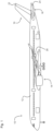
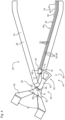
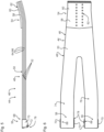
- a top view of a leaf spring;
- Fig. 6
- a side view of a leaf spring;
- Fig. 7
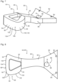
- a perspective view of a cam device;
- Fig. 8
- a top view of the cam device of
Fig. 7 ; - Fig. 9
- a detailed side view of another airfoil structure;
- Fig. 10
- a detailed top view of the airfoil structure of
Fig. 9 ; - Fig. 11 and Fig. 12
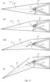
- a sequence of positions I to V of the airfoil structure arrangement of
Fig. 3 being moved in a first direction; and - Fig. 13
- a sequence of positions VI to IX of the airfoil structure arrangement of
Fig. 3 being moved in a second direction. -
Fig. 1 depicts anaircraft 10. In a typical manner theaircraft 10 has afuselage 12. Furthermore, theaircraft 10 compriseswings 14, avertical tail plane 16, and ahorizontal tail plane 18. Thewing 14 comprisesailerons 20. Thevertical tail plane 16 has arudder 22 attached to it. Furthermore, thehorizontal tail plane 18 comprises anelevator 24. - For the sake of brevity, the invention is described in more detail with reference to the
vertical tail plane 16 and therudder 22. However, the skilled person will recognize that the ideas presented herein are also applicable to thewing 14 and theailerons 20 as well as thehorizontal tail plane 18 and theelevator 24. Furthermore, these ideas are applicable to combinations of control surfaces such as elevons and spoilerons. -
Fig. 2 depicts in more detail thevertical tail plane 16 as an example for anairfoil structure arrangement 26. Theairfoil structure arrangement 26 comprises aairfoil mounting structure 28. Theairfoil mounting structure 28 may comprise a plurality ofribs 30, which are covered in manner known per se by anaerodynamic skin 32. In addition, theairfoil mounting structure 28 comprises a plurality of mountingbrackets 34, which provide ahinge 36 for therudder 22. - The
airfoil structure arrangement 26 further comprises therudder 22 as an example for aairfoil structure 38. Theairfoil structure 38 is movably, in this case rotatably, mounted to theairfoil mounting structure 28. In the present example, theairfoil structure 38 has an upper part 40 and alower part 42. -
Fig. 3 and4 depict theairfoil structure arrangement 26, which is provided with anantivibration device 44, which is preferably obtained by using an antivibration kit-of-parts 46. - The antivibration kit-of-
parts 46 includes aspring device 48. Thespring device 48 is configured to generate a spring force F, when the spring device is deflected from a spring neutral position, as shown for instance inFig. 3 and4 . - The
spring device 48 comprises aleaf spring 50. Preferably theleaf spring 50 is made from a fiber composite material. Theleaf spring 50 comprises a plurality of leaf spring layers 52. The leaf spring layers 52 are fixed together at afixed end portion 54 and free to slide relative to each other at afree end portion 56. Preferably thefixed end portion 54 and thefree end portion 56 are spaced apart from each other along the longitudinal direction of theleaf spring 50. In other words, preferably thefixed end portion 54 and thefree end portion 56 are arranged at opposite longitudinal ends of theleaf spring 50. - At the
fixed end portion 54, theleaf spring 50 preferably comprises areinforcement member 58. Thereinforcement member 58 may be made of a light metal or metal alloy, such as aluminum or titanium or respective alloys thereof. Thereinforcement member 58 may be formed as areinforcement plate 60, which is shaped so as to follow the contour defined by theleaf spring 50. - The leaf spring layers 52 are fixed to each other via plurality of fixing
bolts 62, which may also be used to fix thereinforcement member 58 to theleaf spring 50. - Furthermore, the
leaf spring 50 may include a plurality of friction reducing members 64. The friction reducing members 64 are sandwiched between neighboring leaf spring layers 52. The friction reducing members 64 are preferably formed as afriction reducing foil 66. Thefriction reducing foil 66 is made of PTFE, for example. - The
leaf spring 50 further comprises aleaf spring bracket 68, which is arranged at thefree end portion 56. Theleaf spring bracket 68 is preferably fixed to just one of the leaf spring layers 52 so that the remaining leaf spring layers 52 may slide relative to theleaf spring bracket 68. Theleaf spring bracket 68 may comprise twoside plates 70, which are fixed to the oneleaf spring layer 52. Theside plates 70 preferably extend along the whole thickness of theleaf spring 50, so as to support and guide the leaf spring layers 52 in a lateral direction relative to the longitudinal direction ofleaf spring 50. - Furthermore, the
leaf spring bracket 68 comprises aroller 72, which is preferably supported via theside plates 70. - In the present embodiment, the
leaf spring 50 comprises anupper spring part 74 and alower spring part 76, which substantially extend parallel along the mountingbracket 34 and are tilted upwards and downwards, respectively, so as to be able to cross the mountingbracket 34 and be deflected unimpaired. In the present embodiment, both theupper spring part 74 andlower spring part 76 are provided with theleaf spring bracket 68. - The
leaf spring bracket 68 as an example of acontact portion 78 of thespring device 48, wherein thecontact portion 78 is configured and arranged to contact acam device 80. Reference is made toFig. 3 ,Fig. 4 andFig. 7 to 10 for further details of thecam device 80. - The
cam device 80 comprises a camdevice mounting portion 82. The camdevice mounting portion 82 is configured to mount thecam device 80 to theairfoil structure 38. To this end, the camdevice mounting portion 82 may comprise a plurality of mountingopenings 84. - The
cam device 80 is configured or arranged to rotate about a rotational axis R which coincides with the axis of rotation of thehinge 36. Thecam device 80 further comprises ahinge portion 86. Thehinge portion 86 defines the rotational axis R. Thehinge portion 86 is preferably formed as ahinge opening 88, which is arranged adjacent to the camdevice mounting portion 82. - The
cam device 80 furthermore comprises alever portion 90, which extends from thehinge portion 86 and may be tilted with respect to a horizontal plane. Thelever portion 90 contributes in transforming the spring force F into an airfoil torque M. - The
cam device 80 further comprises ahead portion 92, which is adjacent to thelever portion 90 and spaced apart from thehinge portion 86 and the camdevice mounting portion 82 via thelever portion 90. - The
cam device 80 comprises acam 94, which is preferably formed on thehead portion 92. In particular, reference is made toFig. 8 . In a top view of thecam device 80, thecam 94 is formed on a singlelateral side 96 of the cam device and a singlefront side 98 with respect to a longitudinal direction of thecam device 80. - The
cam 94 comprises astationary cam portion 100. Thestationary cam portion 100 is shaped such that the angle of the spring force F remains unchanged, when thecam device 80 is moved about its rotational axis R. - The
stationary cam portion 100 comprises an urgingcam portion 102. The urgingcam portion 102 is preferably arranged at thelateral side 96. The urgingcam portion 102 directs the spring force F in such a manner that the spring force F points perpendicular with respect to a longitudinal direction of theaircraft 10, i.e. the front-rear-direction of the aircraft. Thus, the urgingcam portion 102 keeps the angle relative to the front-rear-direction of theaircraft 10 stationary. - Furthermore, the
stationary cam portion 100 comprises aneutral cam portion 104. Theneutral cam portion 104 is preferably formed on thefront side 98. Theneutral cam portion 104 is shaped such that the spring force F points towards the rotational axis R. Thus, the spring force F does not exert a torque onto theairfoil structure 38. - The urging
cam portion 102 and theneutral cam portion 104 extend for a length relating to a majority of the movement of thecam device 80. In other words, for a majority of the possible rotation of thecam device 80, the angle of the spring force relative to the aircraft longitudinal direction does not change. - Furthermore, the
cam device 80 comprises atransition cam portion 106. Thetransition cam portion 106 is sandwiched between the urgingcam portion 102 and theneutral cam portion 104. Thetransition cam portion 106 is shaped such that the direction of the spring force F changes between the two stationary states defined by thestationary cam portion 100, in particular the urgingcam portion 102 and theneutral cam portion 104. - The function of the antivibration kit-of-
parts 46 will be explained in further detail with reference toFig. 11 to 13 . - Position I depicts the
airfoil structure arrangement 26 in a neutral position. In other words, theairfoil structure 38 is in the neutral position and its angle with respect to the longitudinal direction of theaircraft 10 is 0°. Furthermore, thecam device 80 is also aligned in the cam device neutral position. Thespring device 48, however, is not in its spring neutral position but in a deflected position, which generates the spring force F. Thespring device 48 contacts thecam device 80 via thecontact portion 78. As can be seen from position I, thecontact portion 78 contacts thecam device 80 at thetransition cam portion 106. Thus, the spring force F is transformed by thecam device 80 into an airfoil torque MI, wherein the spring force F is almost perpendicular with respect to the aircraft longitudinal direction. - Position II depicts the
airfoil structure 38 rotated by some angle. Since thecam device 80 is mounted to theairfoil structure 38, thecam device 80 follows the rotational movement about the rotational axis R, so does thespring device 48. In this position II the deflection of thespring device 48 is smaller and thus, the magnitude of the spring force F is also smaller. - Furthermore in position II, the
contact portion 78 now contacts thecam device 80 at the urgingcam portion 102, which redirects the spring force F to be directed laterally with respect to the longitudinal direction of theaircraft 10. Thus, thespring device 48 causes an airfoil torque MII which is smaller than the airfoil torque MI. - As can be seen from positions III and IV, the more the
airfoil structure 38 is rotated, the lesser thespring device 48 is deflected. Thus, the spring force F decreases, when theairfoil structure 38 is rotated in afirst direction 108. The associated airfoil torques MIII and MIV are thus getting subsequently smaller and smaller. - Finally in position V, the
airfoil structure 38 was rotated by a rather large angle, for example an angle of 30 degrees. In this position V, thecam device 80 barely contacts thespring device 48 so that thespring device 48 is almost in its neutral position. If theairfoil structure 38 is moved further, the spring force F and thus the airfoil torque will eventually become zero. - Looking at
Fig. 13 a movement of theairfoil structure 38 in a second direction 110 opposite to thefirst direction 108 is depicted. Initially position VI is the same as position I and is mainly shown for comparison. - In position VII, the
airfoil structure 38 is moved by a small amount in the second direction 110, thereby moving thecam device 80 to increase deflection of thespring device 48. Thus, the spring force F increases due to a larger deflection of thespring device 48. - However, the
contact portion 78 contacts thecam device 80 at thetransition cam portion 106. Relative to position VI, the angle of the spring force F in position VII has changed substantially and is tilted more towards the rotational axis R of theairfoil structure 38. Thus, although the spring force F has increased, the airfoil torque MVII is smaller than the airfoil torque MVI, which is the same as the airfoil torque MI. - In position VIII, the
contact portion 78 contacts thecam device 80 at the beginning of theneutral cam portion 104. Thespring device 48 has now reached maximum deflection, and thus the spring force F is also at maximum. However, due to theneutral cam portion 104 the spring force F is directed towards the rotational axis R such that no effective lever arm is provided by thecam device 80. In other words, the airfoil torque MVIII is 0 Nm due to the redirection of the spring force F by thecam device 80, in particular theneutral cam portion 104. - As depicted in position IX, the
airfoil structure 38 can be rotated by a substantial amount, yet the airfoil torque MIX still equals 0 Nm, since theneutral cam portion 104 continuously directs the spring force F towards the rotational axis R. - As a result, the
cam device 80 is configured such that an airfoil torque Mn only acts upon theairfoil structure 38 when it is rotated in thefirst direction 108, but not the second direction 110, apart from a small transition portion. - In order to reduce vibration of movable airfoil structures, such as rudders, elevators, and ailerons, a spring device, a leaf spring for example, is mounted to a airfoil mounting structure, such as a vertical tail plane, horizontal tail plane or the wings, such that the spring device exerts a force on a cam device, which transforms the spring force into an airfoil torque. The airfoil torque is applied to the airfoil structure and thus reduces a risk of vibration or flutter. The cam device is configured to redirect the spring force such that when the airfoil structure is moved in a first direction, torque decreases and when moved in the opposite second direction the torque is zero.
-
- 10
- aircraft
- 12
- fuselage
- 14
- wing
- 16
- vertical tail plane (VTP)
- 18
- horizontal tail plane (HTP)
- 20
- aileron
- 22
- rudder
- 24
- elevator
- 26
- airfoil structure arrangement
- 28
- airfoil mounting structure
- 30
- rib
- 32
- aerodynamic skin
- 34
- mounting bracket
- 36
- hinge
- 38
- movable airfoil structure
- 40
- upper part
- 42
- lower part
- 44
- antivibration device
- 46
- antivibration kit-of-parts
- 48
- spring device
- 50
- leaf spring
- 52
- leaf spring layer
- 54
- fixed end portion
- 56
- free end portion
- 58
- reinforcement member
- 60
- reinforcement plate
- 62
- fixing bolt
- 64
- friction reducing member
- 66
- friction reducing foil
- 68
- leaf spring bracket
- 70
- side plate
- 72
- roller
- 74
- upper spring part
- 76
- lower spring part
- 78
- contact portion
- 80
- cam device
- 82
- cam device mounting portion
- 84
- mounting opening
- 86
- hinge portion
- 88
- hinge opening
- 90
- lever portion
- 92
- head portion
- 94
- cam
- 96
- lateral side
- 98
- front side
- 100
- stationary cam portion
- 102
- urging cam portion
- 104
- neutral cam portion
- 106
- transition cam portion
- 108
- first direction
- 110
- second direction
- F
- spring force
- M, MN, and MI... MIX
- airfoil torque
- R
- rotational axis
Claims (13)
- Antivibration kit-of-parts (46) configured for reducing vibration of an airfoil structure (38), the airfoil structure (38) being movably attachable to an aircraft (10), wherein the antivibration kit-of-parts (46) comprises:- a spring device (48) configured for generating a spring force (F) due to deflection from a spring neutral position of the spring device (48); and- a cam device (80) configured for transforming the spring force (F) into an airfoil torque (M) while, when both the spring device (48) and the cam device (80) are in an operating condition, the cam device (80) contacts the spring device (48), and the cam device (80) is configured for applying the airfoil torque (M) to the airfoil structure (38) while, when both the spring device (48) and the cam device (80) are in an operating condition, the cam device (80) is operatively coupled to the airfoil structure (38), wherein the cam device (80) comprises a cam device mounting portion (82) configured for mounting the cam device (80) to the airfoil structure (38) and a hinge portion (86) defining an axis of rotation (R) about which the cam device (80) is rotatable,characterized in that the cam device (80) comprises a lever portion (90) that extends from the hinge portion (86) and that is configured to contribute in transforming the spring force (F) into an airfoil torque (M), wherein the cam device (80) comprises a head portion (92) that is adjacent to the lever portion (90) and spaced apart from the hinge portion (86) via the lever portion (90), wherein the cam device (80) comprises a cam (94) that is formed on the head portion (92) and the cam (94) is formed on a single lateral side (96) of the cam device (80) and a single front side (98) with respect to a longitudinal direction of the cam device (80).
- Antivibration kit-of-parts (46) according to claim 1, wherein the cam device (80) is configured- to be rotatable about an axis of rotation, so as to transform the spring force (F) into the airfoil torque (M); and/or- to transform the spring force (F) into the airfoil torque (M) being nonzero, when the cam device (80) is moved from a cam device neutral position in a first direction (108) but not another direction; and/or- to transform the spring force (F) into the airfoil torque (M) being zero when the cam device (80) is moved from a cam device neutral position in a second direction (110) but not another direction, although the spring device (48) stays in contact with the cam device (80); and/or- to transform the spring force (F) into the airfoil torque (M) being zero by directing the spring force (F) to point towards the axis of rotation (R).
- Antivibration kit-of-parts according (46) to any of the preceding claims, wherein, when both the spring device (48) and the cam device (80) are in the operating condition,- the spring device (48) is deflected when the cam device (80) is in a cam device neutral position; and/or- the deflection of the spring device (48) decreases when the cam device (80) is moved from a cam device neutral position in a first direction (108) but not another direction; and/or- the deflection of the spring device (48) stays the same, when the cam device (80) is moved from a cam device neutral position in a second direction (110) but not another direction; and/or- the deflection of the spring device (48) initially increases and subsequently stays the same, when the cam device (80) is moved from a cam device neutral position in a second direction (110) but not another direction.
- Antivibration kit-of-parts (46) according to any of the preceding claims, wherein the spring device (48) comprises a leaf spring (50) configured to generate the spring force (F).
- Antivibration kit-of-parts (46) according to claim 4, wherein the leaf spring (50)- comprises a plurality of leaf spring layers (52) stacked on each other in a sliding manner; and/or- has a fixed end portion (54), at which the leaf spring layers (52) are fixed to each other; and/or- has a free end portion (56), at which the leaf spring layers (52) are free to slide relative to each other; and/or- comprises a friction reducing member (64) sandwiched between two neighbouring leaf spring layers (52); and/or- has a leaf spring bracket (68) configured to support the leaf spring layers (52) in a sliding manner.
- Antivibration kit-of-parts (46) according to any of the preceding claims,- wherein the spring device (48) comprises a contact portion (78) arranged for contacting the cam device (80), so as to transfer the spring force (F) to the cam device (80); and/or- wherein the spring device (48) comprises a reinforcement member (58) configured for reinforcing the spring device (48).
- Antivibration kit-of-parts (46) according to claim 6,- wherein the contact portion (78) is arranged at the free end or the leaf spring bracket (68); and/or- wherein the contact portion (78) comprises a roller (72), which contacts the cam device (80); and/or- wherein the reinforcement member (58) is arranged at the fixed end portion (54).
- Antivibration kit-of-parts (46) according to any of the preceding claims, wherein the cam device (80) comprises a cam portion configured for directing the spring force (F) in such a manner that, when the cam device (80) is in the operating condition, the spring force (F) is directed in the same direction relative to the aircraft for a majority of a movement of the cam device (80) relative to the aircraft (10).
- Airfoil structure arrangement for an aircraft (10), the airfoil structure arrangement (26) comprising a airfoil mounting structure (28), a airfoil structure (38) movably mounted to the airfoil mounting structure (28), and an antivibration kit-of-parts (46) according to any of the preceding claims, wherein the spring device (48) is mounted to the fixed airfoil structure (28) and the cam device (80) is mounted to the airfoil structure (38).
- Airfoil structure arrangement (26) according to claim 9,- wherein the stationary cam portion (100) comprises an urging cam portion (102) configured for directing the spring force (F) such that the spring force (F) is directed parallel to a lateral direction, preferably a left-right-direction or a top-bottom-direction, of the aircraft (10); and/or- wherein the stationary cam portion (100) comprises a neutral cam portion (104) configured for directing the spring force (F) such that the spring force (F) is directed towards an axis of rotation of the cam device (80).
- Airfoil structure arrangement (26) according to claim 9 or 10, wherein the airfoil mounting structure (28) comprises a wing (14), a vertical tail plane (16), and/or a horizontal tail plane (18), and wherein the airfoil structure (38) comprises a control surface or high lift device.
- Aircraft (10), in particular airplane, comprising an airfoil structure according to any of the claims 9 to 11.
- Cam device (80) suitable for an antivibration kit-of-parts (46) according to any of the claims 1 to 8, wherein the cam device (80) comprises a cam device mounting portion (82) configured for mounting the cam device (80) to an airfoil structure, the airfoil structure being movably attached to an aircraft, a hinge portion defining an axis of rotation about which the cam device (80) is rotatable, and a cam comprising a cam portion configured for directing a spring force (F) exerted on the cam portion in such a manner that, when the cam device (80) is in the operating condition, the spring force (F) is directed in the same direction relative to an aircraft (10) for a majority of a rotation of the cam device (80) relative to the aircraft (10),
characterized in that the cam device (80) comprises a lever portion (90) that extends from the hinge portion (86) and that is configured to contribute in transforming the spring force (F) into an airfoil torque (M), wherein the cam device (80) comprises a head portion (92) that is adjacent to the lever portion (90) and spaced apart from the hinge portion (86) via the lever portion (90), wherein the cam (94) is formed on the head portion (92) and on a single lateral side (96) of the cam device (80) and a single front side (98) with respect to a longitudinal direction of the cam device (80).
Applications Claiming Priority (2)
| Application Number | Priority Date | Filing Date | Title |
|---|---|---|---|
| DE102019114313 | 2019-05-28 | ||
| PCT/EP2020/064550 WO2020239753A1 (en) | 2019-05-28 | 2020-05-26 | Antivibration kit-of-parts and parts therefor, airfoil structure and aircraft provided therewith |
Publications (2)
| Publication Number | Publication Date |
|---|---|
| EP3894321A1 EP3894321A1 (en) | 2021-10-20 |
| EP3894321B1 true EP3894321B1 (en) | 2023-07-19 |
Family
ID=70968915
Family Applications (1)
| Application Number | Title | Priority Date | Filing Date |
|---|---|---|---|
| EP20729973.6A Active EP3894321B1 (en) | 2019-05-28 | 2020-05-26 | Antivibration kit-of-parts and parts therefor, airfoil structure and aircraft provided therewith |
Country Status (4)
| Country | Link |
|---|---|
| US (1) | US11840336B2 (en) |
| EP (1) | EP3894321B1 (en) |
| CN (1) | CN113366240A (en) |
| WO (1) | WO2020239753A1 (en) |
Families Citing this family (1)
| Publication number | Priority date | Publication date | Assignee | Title |
|---|---|---|---|---|
| EP3875367B1 (en) * | 2020-03-02 | 2023-08-02 | Safran Landing Systems UK Limited | Aircraft landing gear assembly |
Family Cites Families (15)
| Publication number | Priority date | Publication date | Assignee | Title |
|---|---|---|---|---|
| BE349173A (en) | ||||
| US1371166A (en) * | 1919-12-18 | 1921-03-08 | Thomas S Hamilton | Device for preventing friction between the leaves of leaf-springs |
| FR571743A (en) | 1922-12-21 | 1924-05-22 | Elastic stops for airplanes fins | |
| US2471857A (en) * | 1946-05-09 | 1949-05-31 | Lockheed Aircraft Corp | Flutter damper |
| FR1381162A (en) | 1963-11-18 | 1964-12-04 | Hydraulic steering control device | |
| US3282069A (en) | 1964-11-27 | 1966-11-01 | Bendix Corp | Preloaded override spring device |
| SE368369B (en) | 1972-10-18 | 1974-07-01 | Saab Scania Ab | |
| FR2529839A1 (en) * | 1982-07-06 | 1984-01-13 | Delery Marc | Leaf-type suspension intended especially for vehicles |
| US4753402A (en) | 1985-12-30 | 1988-06-28 | The Boeing Company | Biased leading edge slat apparatus |
| ES2274658B1 (en) | 2003-12-31 | 2008-04-16 | Airbus España, S.L. | MECHANISM TO DELETE LIMIT CYCLE OSCILLATIONS IN SERVOCONTROLATED AERODYNAMIC CONTROL SURFACES. |
| KR100938268B1 (en) | 2007-12-24 | 2010-01-22 | 한국항공우주연구원 | Vibration Prevention Device of Aircraft Control Surface |
| JP5894430B2 (en) * | 2011-12-22 | 2016-03-30 | オイレス工業株式会社 | Silencer for laminated leaf spring and laminated leaf spring |
| US9056668B2 (en) | 2012-07-12 | 2015-06-16 | Honeywell International Inc. | Aircraft control stick operational in active and passive modes |
| US20160159183A1 (en) * | 2014-12-05 | 2016-06-09 | GM Global Technology Operations LLC | Noise reduction for rear suspension leaf spring with tip insert - round head |
| RU2707859C1 (en) * | 2016-03-15 | 2019-11-29 | Нхк Спринг Ко., Лтд. | Element for gap maintaining and leaf spring, in which such element is used |
-
2020
- 2020-05-26 CN CN202080011361.XA patent/CN113366240A/en active Pending
- 2020-05-26 WO PCT/EP2020/064550 patent/WO2020239753A1/en not_active Ceased
- 2020-05-26 EP EP20729973.6A patent/EP3894321B1/en active Active
- 2020-05-26 US US17/424,808 patent/US11840336B2/en active Active
Also Published As
| Publication number | Publication date |
|---|---|
| EP3894321A1 (en) | 2021-10-20 |
| CN113366240A (en) | 2021-09-07 |
| US11840336B2 (en) | 2023-12-12 |
| WO2020239753A1 (en) | 2020-12-03 |
| US20220089272A1 (en) | 2022-03-24 |
Similar Documents
| Publication | Publication Date | Title |
|---|---|---|
| EP2319759B1 (en) | Aircraft control surface | |
| EP2669188B1 (en) | A hinge assembly for rotatably mounting a control surface on an aircraft | |
| EP2134597B1 (en) | Wing | |
| US8844878B2 (en) | High lift system for an aircraft | |
| US6467733B1 (en) | Aerodynamic control surface system | |
| US20070176051A1 (en) | Actuation device positioning systems and associated methods, including aircraft spoiler droop systems | |
| EP0103038A1 (en) | Continuous skin, variable camber airfoil edge actuating mechanism | |
| US6371415B1 (en) | Aerodynamic component with a leading edge flap | |
| EP4324737B1 (en) | An aerofoil | |
| US20160152332A1 (en) | Rotorcraft tail rotor, a rotorcraft fitted with such a tail rotor, and a method of statically and/or dynamically balancing a rotorcraft tail rotor | |
| CN114906314A (en) | Aircraft wing segment assembly | |
| US6076775A (en) | Airfoil with a landing flap having a flexible trailing edge | |
| US9731812B2 (en) | Flap mechanism and associated method | |
| US11840336B2 (en) | Antivibration kit-of-parts and parts therefor, airfoil structure and aircraft provided therewith | |
| US12371149B2 (en) | Multi-functional trailing edge apparatus and methods for aircraft | |
| JP7527694B2 (en) | Aircraft Flight Control System | |
| EP1550607B1 (en) | Mechanism for eliminating limit cycle oscillations on servocontrolled aerodynamic control surfaces | |
| EP4311766B1 (en) | Wing for an aircraft | |
| US5110072A (en) | Control surface stabilizer hinge | |
| US6663345B2 (en) | Rotor blade with control flaps | |
| EP3378759A1 (en) | Airfoil trailing edge high-lift device and actuation system therefore | |
| CN111907694B (en) | Wing trailing edge and wing with variable camber | |
| JP2001058600A (en) | Flap drive device and rotor blade | |
| US20020021965A1 (en) | Rotor blade having a control flap | |
| US20180072412A1 (en) | Adjustment of track and balance of a multi-blade rotor |
Legal Events
| Date | Code | Title | Description |
|---|---|---|---|
| STAA | Information on the status of an ep patent application or granted ep patent |
Free format text: STATUS: UNKNOWN |
|
| STAA | Information on the status of an ep patent application or granted ep patent |
Free format text: STATUS: THE INTERNATIONAL PUBLICATION HAS BEEN MADE |
|
| PUAI | Public reference made under article 153(3) epc to a published international application that has entered the european phase |
Free format text: ORIGINAL CODE: 0009012 |
|
| STAA | Information on the status of an ep patent application or granted ep patent |
Free format text: STATUS: REQUEST FOR EXAMINATION WAS MADE |
|
| 17P | Request for examination filed |
Effective date: 20210714 |
|
| AK | Designated contracting states |
Kind code of ref document: A1 Designated state(s): AL AT BE BG CH CY CZ DE DK EE ES FI FR GB GR HR HU IE IS IT LI LT LU LV MC MK MT NL NO PL PT RO RS SE SI SK SM TR |
|
| DAV | Request for validation of the european patent (deleted) | ||
| DAX | Request for extension of the european patent (deleted) | ||
| RAP3 | Party data changed (applicant data changed or rights of an application transferred) |
Owner name: AIRBUS OPERATIONS GMBH |
|
| GRAP | Despatch of communication of intention to grant a patent |
Free format text: ORIGINAL CODE: EPIDOSNIGR1 |
|
| STAA | Information on the status of an ep patent application or granted ep patent |
Free format text: STATUS: GRANT OF PATENT IS INTENDED |
|
| INTG | Intention to grant announced |
Effective date: 20230214 |
|
| GRAS | Grant fee paid |
Free format text: ORIGINAL CODE: EPIDOSNIGR3 |
|
| GRAA | (expected) grant |
Free format text: ORIGINAL CODE: 0009210 |
|
| STAA | Information on the status of an ep patent application or granted ep patent |
Free format text: STATUS: THE PATENT HAS BEEN GRANTED |
|
| AK | Designated contracting states |
Kind code of ref document: B1 Designated state(s): AL AT BE BG CH CY CZ DE DK EE ES FI FR GB GR HR HU IE IS IT LI LT LU LV MC MK MT NL NO PL PT RO RS SE SI SK SM TR |
|
| REG | Reference to a national code |
Ref country code: GB Ref legal event code: FG4D |
|
| REG | Reference to a national code |
Ref country code: CH Ref legal event code: EP |
|
| REG | Reference to a national code |
Ref country code: DE Ref legal event code: R096 Ref document number: 602020014091 Country of ref document: DE |
|
| REG | Reference to a national code |
Ref country code: IE Ref legal event code: FG4D |
|
| REG | Reference to a national code |
Ref country code: LT Ref legal event code: MG9D |
|
| REG | Reference to a national code |
Ref country code: NL Ref legal event code: MP Effective date: 20230719 |
|
| REG | Reference to a national code |
Ref country code: AT Ref legal event code: MK05 Ref document number: 1589222 Country of ref document: AT Kind code of ref document: T Effective date: 20230719 |
|
| PG25 | Lapsed in a contracting state [announced via postgrant information from national office to epo] |
Ref country code: NL Free format text: LAPSE BECAUSE OF FAILURE TO SUBMIT A TRANSLATION OF THE DESCRIPTION OR TO PAY THE FEE WITHIN THE PRESCRIBED TIME-LIMIT Effective date: 20230719 |
|
| PG25 | Lapsed in a contracting state [announced via postgrant information from national office to epo] |
Ref country code: GR Free format text: LAPSE BECAUSE OF FAILURE TO SUBMIT A TRANSLATION OF THE DESCRIPTION OR TO PAY THE FEE WITHIN THE PRESCRIBED TIME-LIMIT Effective date: 20231020 |
|
| PG25 | Lapsed in a contracting state [announced via postgrant information from national office to epo] |
Ref country code: IS Free format text: LAPSE BECAUSE OF FAILURE TO SUBMIT A TRANSLATION OF THE DESCRIPTION OR TO PAY THE FEE WITHIN THE PRESCRIBED TIME-LIMIT Effective date: 20231119 |
|
| PG25 | Lapsed in a contracting state [announced via postgrant information from national office to epo] |
Ref country code: SE Free format text: LAPSE BECAUSE OF FAILURE TO SUBMIT A TRANSLATION OF THE DESCRIPTION OR TO PAY THE FEE WITHIN THE PRESCRIBED TIME-LIMIT Effective date: 20230719 Ref country code: RS Free format text: LAPSE BECAUSE OF FAILURE TO SUBMIT A TRANSLATION OF THE DESCRIPTION OR TO PAY THE FEE WITHIN THE PRESCRIBED TIME-LIMIT Effective date: 20230719 Ref country code: PT Free format text: LAPSE BECAUSE OF FAILURE TO SUBMIT A TRANSLATION OF THE DESCRIPTION OR TO PAY THE FEE WITHIN THE PRESCRIBED TIME-LIMIT Effective date: 20231120 Ref country code: NO Free format text: LAPSE BECAUSE OF FAILURE TO SUBMIT A TRANSLATION OF THE DESCRIPTION OR TO PAY THE FEE WITHIN THE PRESCRIBED TIME-LIMIT Effective date: 20231019 Ref country code: LV Free format text: LAPSE BECAUSE OF FAILURE TO SUBMIT A TRANSLATION OF THE DESCRIPTION OR TO PAY THE FEE WITHIN THE PRESCRIBED TIME-LIMIT Effective date: 20230719 Ref country code: LT Free format text: LAPSE BECAUSE OF FAILURE TO SUBMIT A TRANSLATION OF THE DESCRIPTION OR TO PAY THE FEE WITHIN THE PRESCRIBED TIME-LIMIT Effective date: 20230719 Ref country code: IS Free format text: LAPSE BECAUSE OF FAILURE TO SUBMIT A TRANSLATION OF THE DESCRIPTION OR TO PAY THE FEE WITHIN THE PRESCRIBED TIME-LIMIT Effective date: 20231119 Ref country code: HR Free format text: LAPSE BECAUSE OF FAILURE TO SUBMIT A TRANSLATION OF THE DESCRIPTION OR TO PAY THE FEE WITHIN THE PRESCRIBED TIME-LIMIT Effective date: 20230719 Ref country code: GR Free format text: LAPSE BECAUSE OF FAILURE TO SUBMIT A TRANSLATION OF THE DESCRIPTION OR TO PAY THE FEE WITHIN THE PRESCRIBED TIME-LIMIT Effective date: 20231020 Ref country code: FI Free format text: LAPSE BECAUSE OF FAILURE TO SUBMIT A TRANSLATION OF THE DESCRIPTION OR TO PAY THE FEE WITHIN THE PRESCRIBED TIME-LIMIT Effective date: 20230719 Ref country code: AT Free format text: LAPSE BECAUSE OF FAILURE TO SUBMIT A TRANSLATION OF THE DESCRIPTION OR TO PAY THE FEE WITHIN THE PRESCRIBED TIME-LIMIT Effective date: 20230719 |
|
| PG25 | Lapsed in a contracting state [announced via postgrant information from national office to epo] |
Ref country code: PL Free format text: LAPSE BECAUSE OF FAILURE TO SUBMIT A TRANSLATION OF THE DESCRIPTION OR TO PAY THE FEE WITHIN THE PRESCRIBED TIME-LIMIT Effective date: 20230719 |
|
| REG | Reference to a national code |
Ref country code: DE Ref legal event code: R097 Ref document number: 602020014091 Country of ref document: DE |
|
| PG25 | Lapsed in a contracting state [announced via postgrant information from national office to epo] |
Ref country code: ES Free format text: LAPSE BECAUSE OF FAILURE TO SUBMIT A TRANSLATION OF THE DESCRIPTION OR TO PAY THE FEE WITHIN THE PRESCRIBED TIME-LIMIT Effective date: 20230719 |
|
| PG25 | Lapsed in a contracting state [announced via postgrant information from national office to epo] |
Ref country code: SM Free format text: LAPSE BECAUSE OF FAILURE TO SUBMIT A TRANSLATION OF THE DESCRIPTION OR TO PAY THE FEE WITHIN THE PRESCRIBED TIME-LIMIT Effective date: 20230719 Ref country code: RO Free format text: LAPSE BECAUSE OF FAILURE TO SUBMIT A TRANSLATION OF THE DESCRIPTION OR TO PAY THE FEE WITHIN THE PRESCRIBED TIME-LIMIT Effective date: 20230719 Ref country code: ES Free format text: LAPSE BECAUSE OF FAILURE TO SUBMIT A TRANSLATION OF THE DESCRIPTION OR TO PAY THE FEE WITHIN THE PRESCRIBED TIME-LIMIT Effective date: 20230719 Ref country code: EE Free format text: LAPSE BECAUSE OF FAILURE TO SUBMIT A TRANSLATION OF THE DESCRIPTION OR TO PAY THE FEE WITHIN THE PRESCRIBED TIME-LIMIT Effective date: 20230719 Ref country code: DK Free format text: LAPSE BECAUSE OF FAILURE TO SUBMIT A TRANSLATION OF THE DESCRIPTION OR TO PAY THE FEE WITHIN THE PRESCRIBED TIME-LIMIT Effective date: 20230719 Ref country code: CZ Free format text: LAPSE BECAUSE OF FAILURE TO SUBMIT A TRANSLATION OF THE DESCRIPTION OR TO PAY THE FEE WITHIN THE PRESCRIBED TIME-LIMIT Effective date: 20230719 Ref country code: SK Free format text: LAPSE BECAUSE OF FAILURE TO SUBMIT A TRANSLATION OF THE DESCRIPTION OR TO PAY THE FEE WITHIN THE PRESCRIBED TIME-LIMIT Effective date: 20230719 |
|
| PLBE | No opposition filed within time limit |
Free format text: ORIGINAL CODE: 0009261 |
|
| STAA | Information on the status of an ep patent application or granted ep patent |
Free format text: STATUS: NO OPPOSITION FILED WITHIN TIME LIMIT |
|
| PG25 | Lapsed in a contracting state [announced via postgrant information from national office to epo] |
Ref country code: IT Free format text: LAPSE BECAUSE OF FAILURE TO SUBMIT A TRANSLATION OF THE DESCRIPTION OR TO PAY THE FEE WITHIN THE PRESCRIBED TIME-LIMIT Effective date: 20230719 |
|
| 26N | No opposition filed |
Effective date: 20240422 |
|
| PG25 | Lapsed in a contracting state [announced via postgrant information from national office to epo] |
Ref country code: SI Free format text: LAPSE BECAUSE OF FAILURE TO SUBMIT A TRANSLATION OF THE DESCRIPTION OR TO PAY THE FEE WITHIN THE PRESCRIBED TIME-LIMIT Effective date: 20230719 |
|
| PG25 | Lapsed in a contracting state [announced via postgrant information from national office to epo] |
Ref country code: BG Free format text: LAPSE BECAUSE OF FAILURE TO SUBMIT A TRANSLATION OF THE DESCRIPTION OR TO PAY THE FEE WITHIN THE PRESCRIBED TIME-LIMIT Effective date: 20230719 |
|
| PG25 | Lapsed in a contracting state [announced via postgrant information from national office to epo] |
Ref country code: BG Free format text: LAPSE BECAUSE OF FAILURE TO SUBMIT A TRANSLATION OF THE DESCRIPTION OR TO PAY THE FEE WITHIN THE PRESCRIBED TIME-LIMIT Effective date: 20230719 |
|
| REG | Reference to a national code |
Ref country code: CH Ref legal event code: PL |
|
| PG25 | Lapsed in a contracting state [announced via postgrant information from national office to epo] |
Ref country code: MC Free format text: LAPSE BECAUSE OF FAILURE TO SUBMIT A TRANSLATION OF THE DESCRIPTION OR TO PAY THE FEE WITHIN THE PRESCRIBED TIME-LIMIT Effective date: 20230719 |
|
| PG25 | Lapsed in a contracting state [announced via postgrant information from national office to epo] |
Ref country code: LU Free format text: LAPSE BECAUSE OF NON-PAYMENT OF DUE FEES Effective date: 20240526 |
|
| PG25 | Lapsed in a contracting state [announced via postgrant information from national office to epo] |
Ref country code: MC Free format text: LAPSE BECAUSE OF FAILURE TO SUBMIT A TRANSLATION OF THE DESCRIPTION OR TO PAY THE FEE WITHIN THE PRESCRIBED TIME-LIMIT Effective date: 20230719 Ref country code: LU Free format text: LAPSE BECAUSE OF NON-PAYMENT OF DUE FEES Effective date: 20240526 Ref country code: CH Free format text: LAPSE BECAUSE OF NON-PAYMENT OF DUE FEES Effective date: 20240531 |
|
| REG | Reference to a national code |
Ref country code: BE Ref legal event code: MM Effective date: 20240531 |
|
| PG25 | Lapsed in a contracting state [announced via postgrant information from national office to epo] |
Ref country code: IE Free format text: LAPSE BECAUSE OF NON-PAYMENT OF DUE FEES Effective date: 20240526 |
|
| PG25 | Lapsed in a contracting state [announced via postgrant information from national office to epo] |
Ref country code: BE Free format text: LAPSE BECAUSE OF NON-PAYMENT OF DUE FEES Effective date: 20240531 |
|
| PGFP | Annual fee paid to national office [announced via postgrant information from national office to epo] |
Ref country code: DE Payment date: 20250521 Year of fee payment: 6 |
|
| PGFP | Annual fee paid to national office [announced via postgrant information from national office to epo] |
Ref country code: GB Payment date: 20250527 Year of fee payment: 6 |
|
| PGFP | Annual fee paid to national office [announced via postgrant information from national office to epo] |
Ref country code: FR Payment date: 20250528 Year of fee payment: 6 |
|
| PG25 | Lapsed in a contracting state [announced via postgrant information from national office to epo] |
Ref country code: HU Free format text: LAPSE BECAUSE OF FAILURE TO SUBMIT A TRANSLATION OF THE DESCRIPTION OR TO PAY THE FEE WITHIN THE PRESCRIBED TIME-LIMIT; INVALID AB INITIO Effective date: 20200526 |
|
| PG25 | Lapsed in a contracting state [announced via postgrant information from national office to epo] |
Ref country code: CY Free format text: LAPSE BECAUSE OF FAILURE TO SUBMIT A TRANSLATION OF THE DESCRIPTION OR TO PAY THE FEE WITHIN THE PRESCRIBED TIME-LIMIT; INVALID AB INITIO Effective date: 20200526 |