EP1550607A1 - Mechanism for eliminating limit cycle oscillations on servocontrolled aerodynamic control surfaces - Google Patents
Mechanism for eliminating limit cycle oscillations on servocontrolled aerodynamic control surfaces Download PDFInfo
- Publication number
- EP1550607A1 EP1550607A1 EP04380284A EP04380284A EP1550607A1 EP 1550607 A1 EP1550607 A1 EP 1550607A1 EP 04380284 A EP04380284 A EP 04380284A EP 04380284 A EP04380284 A EP 04380284A EP 1550607 A1 EP1550607 A1 EP 1550607A1
- Authority
- EP
- European Patent Office
- Prior art keywords
- control surface
- cam
- servocontrolled
- elastic element
- control
- Prior art date
- Legal status (The legal status is an assumption and is not a legal conclusion. Google has not performed a legal analysis and makes no representation as to the accuracy of the status listed.)
- Granted
Links
- 230000010355 oscillation Effects 0.000 title claims description 14
- 238000004519 manufacturing process Methods 0.000 claims abstract description 3
- 230000007935 neutral effect Effects 0.000 abstract description 4
- 230000015572 biosynthetic process Effects 0.000 abstract 1
- 239000003381 stabilizer Substances 0.000 description 5
- 238000004873 anchoring Methods 0.000 description 2
- 230000000694 effects Effects 0.000 description 2
- RZVHIXYEVGDQDX-UHFFFAOYSA-N 9,10-anthraquinone Chemical compound C1=CC=C2C(=O)C3=CC=CC=C3C(=O)C2=C1 RZVHIXYEVGDQDX-UHFFFAOYSA-N 0.000 description 1
- 238000012423 maintenance Methods 0.000 description 1
- 238000005457 optimization Methods 0.000 description 1
- 238000003825 pressing Methods 0.000 description 1
- 230000000087 stabilizing effect Effects 0.000 description 1
Images


Classifications
-
- B—PERFORMING OPERATIONS; TRANSPORTING
- B64—AIRCRAFT; AVIATION; COSMONAUTICS
- B64C—AEROPLANES; HELICOPTERS
- B64C9/00—Adjustable control surfaces or members, e.g. rudders
- B64C9/02—Mounting or supporting thereof
-
- B—PERFORMING OPERATIONS; TRANSPORTING
- B64—AIRCRAFT; AVIATION; COSMONAUTICS
- B64C—AEROPLANES; HELICOPTERS
- B64C13/00—Control systems or transmitting systems for actuating flying-control surfaces, lift-increasing flaps, air brakes, or spoilers
- B64C13/24—Transmitting means
- B64C13/38—Transmitting means with power amplification
-
- B—PERFORMING OPERATIONS; TRANSPORTING
- B64—AIRCRAFT; AVIATION; COSMONAUTICS
- B64C—AEROPLANES; HELICOPTERS
- B64C9/00—Adjustable control surfaces or members, e.g. rudders
- B64C9/30—Balancing hinged surfaces, e.g. dynamically
Definitions
- the present invention refers to a mechanism for eliminating limit cycle oscillations on servocontrolled aerodynamic control services, which provides outstanding relevant and advantageous characteristics over other devices used nowadays for the same purpose.
- Aerodynamic control surfaces are prone to endure dynamic instability in flight. These are some of the factors that contribute to producing said dynamic instability in flight:
- the mechanism for eliminating limit cycle oscillations on servocontrolled aerodynamic control surfaces, object of the invention achieve this effect without a need for a greater surface mass balance, greater structural rigidity, or reduced free play of the bearings or joint elements.
- the mechanism in question includes an elastic element, such as a spring or torsion bar that is fixed to the structure or stabilizer to which the control surface or rudder is connected.
- This elastic element has on its active end an articulated connecting rod or radial lever that ends in a roller that remains in this way constantly applying pressure against the profile of a cam that is rigidly connected to the control surface.
- the roller produces angular deformation of the elastic element, varying the elastic reaction momentum or force depending on the profile of the cam.
- the shape of the cam regulates the force torque on the rudder so that:
- the elastic element loads the control surface with a torque around the line of hinges, which is maximum in the neutral position of the control surface, and then reduces progressively to "0" since the positive and negative deflections of the control surface increase, in the specified manner.
- the rudder (1) is controlled by the actuator (5) anchored between the supports (6) and (7) respectively integral to the stabilizer and the rudder. These anchorings are jointed since they comprise the forked ties.
- FIG. 1 schematically shows the place where this mechanism that actuates the cam (9) integral to the rudder and arranged perpendicularly to the rotation axis (2), is located.
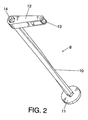
- the mechanism (8) is formed by the elastic element (10), materialized in this case by a torsion bar, which is anchored by one of its ends to the disk (11) or the element fixed without the possibility of movement to the fixed part of the structure or stabilizer (4), as seen in figure 1.
- the anchoring point of the torsion bar (10) has a square section for total immobilization of the bar (10).
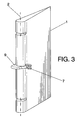
- the active or movable end of the torsion bar (10) has the articulated connecting rod (12) or radial lever ending in a fork inserted in order to mount between the branches thereof the following roller (13) of the profile of the cam (9), not represented in figure 2 since it corresponds to the rudder (1) since it is integral thereto as shown in figure 3.
- Reference 14 of figure 2 designates the support bearing of the end of the torsion bar (10) in order to control the rotation thereof.
- the following roller (13) Due to the preloading of the torsion bar (10), or elastic torsional element, the following roller (13) always contacts under pressure the profile or roller track of the cam (9), producing rotation momentum always of the same sign on the cam, irrespective of whether angular movement of the rudder is produced in one direction or the other.
Landscapes
- Engineering & Computer Science (AREA)
- Aviation & Aerospace Engineering (AREA)
- Automation & Control Theory (AREA)
- Mechanical Control Devices (AREA)
- Transmission Devices (AREA)
- Toys (AREA)
- Support Of The Bearing (AREA)
Abstract
Description
- As expressed in the title of this specification, the present invention, refers to a mechanism for eliminating limit cycle oscillations on servocontrolled aerodynamic control services, which provides outstanding relevant and advantageous characteristics over other devices used nowadays for the same purpose.
- These aerodynamic surfaces are hinged or generally jointed to a fixed structure and the rotation thereof controlled by the pilot or by automatic flight control systems, produces momenta and aerodynamic forces that stabilize and control the spacecraft, such as depth rudders, direction rudders and ailerons.
- Aerodynamic control surfaces are prone to endure dynamic instability in flight. These are some of the factors that contribute to producing said dynamic instability in flight:
- Optimization of the weight of the control surfaces and primary surfaces to which they are connected, whose results are lighter and less rigid structures.
- Flight speed: the increase of the flight speed increases the tendency for instability.
- Size of the control surface: The larger the control surface, the greater the tendency for dynamic instability due to greater inertia. These contributing factors have become obvious during the creation of very big and new generation airships.
- Servoactuators and servoactuator supports: their rigidity is a fundamental element when stabilizing the dynamics of the control surfaces. However, the balance between rigidity and inertia worsens as the size of the control surface increases.
- Free play in the connections of the servoactuators and on the control surface that support the hinge axis or line of hinges.
- There should not be dynamic instability on the aerodynamic control surfaces under normal conditions nor even when there are failures. The probability that instability is produced should be lower than that specified in the regulations or applicable and suitable requirements for safe operation of the spacecraft. As we have indicated above, in modern airplanes with servocontrolled control surfaces, the servoactuators play a crucial role in dynamic stability.
- However, it frequently happens that a dynamically stable control surface equipped with servoactuators becomes dynamically instable if the servoactuators do not operate. Given that the supports of the line of hinges of the control surface and the servoactuators will be exposed to the free play as a result of the manufacturing tolerances and the wear of the bearings and similar joint elements that facilitate rotation of the control surface, the natural tendency is that the control surface is dynamically instable, the range of oscillations is somewhat higher than the free play existing in the joints. This dynamic instability leads to the phenomenon normally known as limit cyclical oscillations of the control surface, which in turn result in momenta and forces that are transmitted to the airship.
- Depending on the range and frequency of these resulting limit cycle oscillations, the vibrations of the airship may disturb the crew and the passengers or, if they are great enough, they jeopardize the safety of the flight. On the other hand, these oscillations, even if they are so small that the crew does not manage to notice them, they will result in an increase of damage due to fatigue and greater wear of the affected parts.
- Although nowadays great efforts are being made in order to reduce play, it is inevitable that it exists due to wear. To eliminate limit cycle oscillations, costly maintenance that guarantees that the play is kept within some minimums is required. Other types of measures such as balancing the weight of the control surface by adding counterweights, or else, increasing the structural rigidity, which involves disadvantages due to weight, are resorted to.
- In broad outline, the mechanism for eliminating limit cycle oscillations on servocontrolled aerodynamic control surfaces, object of the invention, achieve this effect without a need for a greater surface mass balance, greater structural rigidity, or reduced free play of the bearings or joint elements.
- The mechanism in question includes an elastic element, such as a spring or torsion bar that is fixed to the structure or stabilizer to which the control surface or rudder is connected. This elastic element has on its active end an articulated connecting rod or radial lever that ends in a roller that remains in this way constantly applying pressure against the profile of a cam that is rigidly connected to the control surface. When the control surface is deflected, the roller produces angular deformation of the elastic element, varying the elastic reaction momentum or force depending on the profile of the cam. In this way, when the control surface is rotated around the hinged axis, the shape of the cam regulates the force torque on the rudder so that:
- a) The control surface can rotate around the hinged axis in the range of specified deviations without producing obstruction or limitation of movement.
- b) The elastic element causes the following roller of the cam to be continuously in contact with the profile thereof in the complete range of positive and negative deviations of the control surface or rudder.
- c) Deformation of the elastic element is not
linearly related to the rotation surface, but rather:
- deformation thereof is always greater than a specified threshold and is always in the same direction.
- The normal pressurized contact force, with which the roller attacks the cam, produces momentum around the rotation axis that varies nonlinearly since the control surface deviates angularly. The momentum is maximum around the neutral position and reduces until it is eliminated in practical terms for positive and negative angular deviations of the control surfaces, that exceed the specified thresholds, since the profile of the cam in its end areas is concentrically circular to the rotation axis.
-
- In this way, the elastic element loads the control surface with a torque around the line of hinges, which is maximum in the neutral position of the control surface, and then reduces progressively to "0" since the positive and negative deflections of the control surface increase, in the specified manner.
- By means of this elastic load, that acts on the control surface aside from the aerodynamic actions. the control surface is forced against the servoactuator reducing in this way the effect of the play of the joint elements on the limit cycle oscillations. Any oscillation may be eliminated according to the invention, with great benefits as for weight, aerodynamic resistance, or cost with regard to known systems, such as the above-mentioned mass balance, increase of rigidity, loads produced by an aerodynamic control surface, or systems based on active servosystems.
- In order to provide a better understanding of the characteristics of the invention and forming an integral part of this specification, some sheets of drawings whose figures represent the following in an illustrative and non-restrictive manner, are attached hereto:
-
- Figure 1 is a perspective schematic view of the mechanism for eliminating limit cycle oscillations on servocontrolled aerodynamic control surfaces, object of the invention, applied to a rudder aided by a servoactuator connected to a stabilizer of an airplane.
- Figure 2 is a perspective and larger scale view of the same mechanism as in figure 1, without including the cam.
- Figure 3 is a larger scale perspective view of the same rudder as in figure 1 in order to clearly show the rotation axis and the fittings where the actuator is connected, as well as the position of the cam.
- Figure 4 is a schematic view of the operating of the mechanism object of the invention.
-
- Making reference to the numbering used in the figures, we can see how the mechanism for eliminating limit cycle oscillations on servocontrolled aerodynamic control surfaces, that the invention proposes, is applied in this case to the control of the rudder (1) that joints on the hinged axis line (2), passing through the bearing supports (3) connected to the fixed element or the stabilizer (4) of the airplane.
- The rudder (1) is controlled by the actuator (5) anchored between the supports (6) and (7) respectively integral to the stabilizer and the rudder. These anchorings are jointed since they comprise the forked ties.
- The mechanism for eliminating the limit cycle oscillations on this rudder (1) is generally referred to as number (8) and its shape is more clearly seen in figure 2. Figure 1 schematically shows the place where this mechanism that actuates the cam (9) integral to the rudder and arranged perpendicularly to the rotation axis (2), is located.
- The mechanism (8) is formed by the elastic element (10), materialized in this case by a torsion bar, which is anchored by one of its ends to the disk (11) or the element fixed without the possibility of movement to the fixed part of the structure or stabilizer (4), as seen in figure 1. The anchoring point of the torsion bar (10) has a square section for total immobilization of the bar (10). The active or movable end of the torsion bar (10) has the articulated connecting rod (12) or radial lever ending in a fork inserted in order to mount between the branches thereof the following roller (13) of the profile of the cam (9), not represented in figure 2 since it corresponds to the rudder (1) since it is integral thereto as shown in figure 3.
-
Reference 14 of figure 2 designates the support bearing of the end of the torsion bar (10) in order to control the rotation thereof. - Due to the preloading of the torsion bar (10), or elastic torsional element, the following roller (13) always contacts under pressure the profile or roller track of the cam (9), producing rotation momentum always of the same sign on the cam, irrespective of whether angular movement of the rudder is produced in one direction or the other.
- Now analyzing figure 4, we can schematically see the operation of the mechanism, obtaining a torque (F x a) on the rudder (12) when the rudder is deflecting an α angle. One can also see that the articulated connecting rod (12) is deviated with a β angle (that will always have the same sign). The cited torque is maximum in the neutral position of the rudder (α = 0), being "0" when the following roller (13) reaches the circular sections of the cam(9) profile since the normal one at the tangent point of the roller in these sections passes through the center, or intersection with the rotation axis.
Claims (1)
- Mechanism for eliminating limit cycle oscillations on servocontrolled aerodynamic control surfaces, these surfaces being equipped with servoactuators and whose supports of the rotation axis or the hinged axis, determine free play between the manufacturing tolerances and the wear of the bearings or joint elements, characterized in that it includes an elastic element (10), spring or torsion bar, fixed to the structure (4) wherein the control surface (1) is jointed, to which an articulated rod (12) is rigidly connected, an articulated rod provided in its ends with a following roller (13) of a cam (9) integral to the control surface (1) and with a profile that produces continuous nonlinear deformation, of the elastic element (10) defining a force torque on the control surface, that reduces when the deviations of the control surface (1) increase, being "0" for positive and negative deviations that exceed a preestablished angular value.
Applications Claiming Priority (2)
| Application Number | Priority Date | Filing Date | Title |
|---|---|---|---|
| ES200303084A ES2274658B1 (en) | 2003-12-31 | 2003-12-31 | MECHANISM TO DELETE LIMIT CYCLE OSCILLATIONS IN SERVOCONTROLATED AERODYNAMIC CONTROL SURFACES. |
| ES200303084 | 2003-12-31 |
Publications (2)
| Publication Number | Publication Date |
|---|---|
| EP1550607A1 true EP1550607A1 (en) | 2005-07-06 |
| EP1550607B1 EP1550607B1 (en) | 2007-11-21 |
Family
ID=34566020
Family Applications (1)
| Application Number | Title | Priority Date | Filing Date |
|---|---|---|---|
| EP04380284A Expired - Lifetime EP1550607B1 (en) | 2003-12-31 | 2004-12-30 | Mechanism for eliminating limit cycle oscillations on servocontrolled aerodynamic control surfaces |
Country Status (4)
| Country | Link |
|---|---|
| US (1) | US7175132B2 (en) |
| EP (1) | EP1550607B1 (en) |
| DE (1) | DE602004010225D1 (en) |
| ES (2) | ES2274658B1 (en) |
Cited By (3)
| Publication number | Priority date | Publication date | Assignee | Title |
|---|---|---|---|---|
| FR2906220A1 (en) * | 2006-09-21 | 2008-03-28 | Airbus France Sas | Aircraft i.e. supersonic aircraft, has aileron integrated to torque shaft turning around rotational axis, and torque shaft widely extending over free end of wing inside pod fixed to free end, where servo-controls are arranged inside pod |
| CN109080814A (en) * | 2018-09-30 | 2018-12-25 | 西安爱生技术集团公司 | A kind of full-height foam core unmanned plane lifting rudder face shaft installing mechanism |
| WO2020239753A1 (en) * | 2019-05-28 | 2020-12-03 | Airbus Operations Gmbh | Antivibration kit-of-parts and parts therefor, airfoil structure and aircraft provided therewith |
Families Citing this family (9)
| Publication number | Priority date | Publication date | Assignee | Title |
|---|---|---|---|---|
| US7229046B2 (en) * | 2005-10-25 | 2007-06-12 | Durant Cecil John | Servo mounting system for direct drive of an aircraft control surface |
| KR100938268B1 (en) * | 2007-12-24 | 2010-01-22 | 한국항공우주연구원 | Vibration Prevention Device of Aircraft Control Surface |
| DE102012006187B4 (en) * | 2012-03-27 | 2020-03-12 | Airbus Operations Gmbh | Flap arrangement and aircraft with at least one flap arrangement |
| FR2993858B1 (en) * | 2012-07-27 | 2014-08-22 | Thales Sa | METHOD FOR TORQUE CONTROL OF AN ANGULAR POSITION CONTROLLED ACTUATOR OF A MECHANICAL FLIGHT CONTROL AIRCRAFT |
| CN103661924A (en) * | 2012-08-31 | 2014-03-26 | 北京精密机电控制设备研究所 | Connecting structure of servo motor output shaft and rudder |
| US20150360768A1 (en) * | 2014-06-12 | 2015-12-17 | Troy A. Woodland | Mounting assembly for fully automatic slat |
| RU183352U1 (en) * | 2017-09-21 | 2018-09-18 | Федеральное государственное унитарное предприятие "Центральный аэрогидродинамический институт имени профессора Н.Е. Жуковского" (ФГУП "ЦАГИ") | The control mechanism of the steering surface of the aerodynamic model of the aircraft |
| CN111703568A (en) * | 2020-05-07 | 2020-09-25 | 北京星途探索科技有限公司 | Wing rudder layout for enhancing roll control capability of hypersonic aircraft |
| RU207155U1 (en) * | 2021-07-13 | 2021-10-14 | Федеральное государственное унитарное предприятие "Центральный аэрогидродинамический институт имени профессора Н.Е. Жуковского" (ФГУП "ЦАГИ") | The mechanism of deflection of the trailing edge of the wing of the aerodynamic model of the aircraft |
Citations (2)
| Publication number | Priority date | Publication date | Assignee | Title |
|---|---|---|---|---|
| US4173322A (en) * | 1978-04-27 | 1979-11-06 | The United States Of America As Represented By The Secretary Of The Air Force | Flutter prevention means for aircraft primary flight control surfaces |
| US4498647A (en) * | 1982-03-15 | 1985-02-12 | Mcdonnel Douglas Corporation | Surface hold-down mechanism |
Family Cites Families (2)
| Publication number | Priority date | Publication date | Assignee | Title |
|---|---|---|---|---|
| US2254473A (en) * | 1935-01-16 | 1941-09-02 | Bell George W De | Airplane vibration dampener |
| US2471857A (en) * | 1946-05-09 | 1949-05-31 | Lockheed Aircraft Corp | Flutter damper |
-
2003
- 2003-12-31 ES ES200303084A patent/ES2274658B1/en not_active Expired - Fee Related
-
2004
- 2004-12-30 DE DE602004010225T patent/DE602004010225D1/en not_active Expired - Lifetime
- 2004-12-30 US US11/027,834 patent/US7175132B2/en not_active Expired - Lifetime
- 2004-12-30 ES ES04380284T patent/ES2297361T3/en not_active Expired - Lifetime
- 2004-12-30 EP EP04380284A patent/EP1550607B1/en not_active Expired - Lifetime
Patent Citations (2)
| Publication number | Priority date | Publication date | Assignee | Title |
|---|---|---|---|---|
| US4173322A (en) * | 1978-04-27 | 1979-11-06 | The United States Of America As Represented By The Secretary Of The Air Force | Flutter prevention means for aircraft primary flight control surfaces |
| US4498647A (en) * | 1982-03-15 | 1985-02-12 | Mcdonnel Douglas Corporation | Surface hold-down mechanism |
Cited By (4)
| Publication number | Priority date | Publication date | Assignee | Title |
|---|---|---|---|---|
| FR2906220A1 (en) * | 2006-09-21 | 2008-03-28 | Airbus France Sas | Aircraft i.e. supersonic aircraft, has aileron integrated to torque shaft turning around rotational axis, and torque shaft widely extending over free end of wing inside pod fixed to free end, where servo-controls are arranged inside pod |
| CN109080814A (en) * | 2018-09-30 | 2018-12-25 | 西安爱生技术集团公司 | A kind of full-height foam core unmanned plane lifting rudder face shaft installing mechanism |
| WO2020239753A1 (en) * | 2019-05-28 | 2020-12-03 | Airbus Operations Gmbh | Antivibration kit-of-parts and parts therefor, airfoil structure and aircraft provided therewith |
| US11840336B2 (en) | 2019-05-28 | 2023-12-12 | Airbus Operations Gmbh | Antivibration kit-of-parts and parts therefor, airfoil structure and aircraft provided therewith |
Also Published As
| Publication number | Publication date |
|---|---|
| ES2274658B1 (en) | 2008-04-16 |
| US7175132B2 (en) | 2007-02-13 |
| US20050178897A1 (en) | 2005-08-18 |
| DE602004010225D1 (en) | 2008-01-03 |
| ES2297361T3 (en) | 2008-05-01 |
| EP1550607B1 (en) | 2007-11-21 |
| ES2274658A1 (en) | 2007-05-16 |
Similar Documents
| Publication | Publication Date | Title |
|---|---|---|
| US20240116628A1 (en) | Redundant load path for powered lift tilt actuator | |
| US7175132B2 (en) | Mechanism for eliminating limit cycle oscillations on servocontrolled aerodynamic control surfaces | |
| US9527577B2 (en) | Rotorcraft with a fuselage and at least one main rotor | |
| EP2641831B1 (en) | Helicopter skid type landing gear | |
| US9340278B2 (en) | Flight control system | |
| US8056865B2 (en) | Mechanism for changing the shape of a control surface | |
| US10479494B2 (en) | Rotorcraft tail rotor, a rotorcraft fitted with such a tail rotor, and a method of statically and/or dynamically balancing a rotorcraft tail rotor | |
| EP4001107B1 (en) | Light-weight elastic teeter bearing for a rotor and aircraft having such bearing | |
| US4498647A (en) | Surface hold-down mechanism | |
| US6371415B1 (en) | Aerodynamic component with a leading edge flap | |
| US20160236773A1 (en) | Dynamic pitch adjustment devices, systems, and methods | |
| US11198503B2 (en) | Aircraft with active support | |
| US20090324406A1 (en) | Blade for reducing the drag movements of said blade, and a method of reducing such a drag movement | |
| US20140263848A1 (en) | Reversible flight control systems | |
| EP1226070A1 (en) | A hinge for movable control surfaces in an aircraft and a connecting piece to be used with such a hinge | |
| EP4558399A1 (en) | Redundant load path for powered lift tilt actuator | |
| EP3412565A1 (en) | Landing gear | |
| US20030026696A1 (en) | Rotor blade with control flaps | |
| EP3617066B1 (en) | Redundant impact-resistant structure | |
| US20170355447A1 (en) | Thrust-Dependent Variable Blade Pitch Propeller | |
| WO2024076966A1 (en) | Redundant load path for powered lift tilt actuator | |
| CN113366240A (en) | Vibration-proof component kit, component thereof, wing-shaped structure and aircraft provided with wing-shaped structure | |
| US2254473A (en) | Airplane vibration dampener | |
| US12179904B2 (en) | Compliant root structure for connecting an airfoil to a fuselage | |
| US3261573A (en) | Aircraft control system |
Legal Events
| Date | Code | Title | Description |
|---|---|---|---|
| PUAI | Public reference made under article 153(3) epc to a published international application that has entered the european phase |
Free format text: ORIGINAL CODE: 0009012 |
|
| AK | Designated contracting states |
Kind code of ref document: A1 Designated state(s): AT BE BG CH CY CZ DE DK EE ES FI FR GB GR HU IE IS IT LI LT LU MC NL PL PT RO SE SI SK TR |
|
| AX | Request for extension of the european patent |
Extension state: AL BA HR LV MK YU |
|
| 17P | Request for examination filed |
Effective date: 20060105 |
|
| AKX | Designation fees paid |
Designated state(s): AT BE BG CH CY CZ DE DK EE ES FI FR GB GR HU IE IS IT LI LT LU MC NL PL PT RO SE SI SK TR |
|
| 17Q | First examination report despatched |
Effective date: 20060310 |
|
| GRAP | Despatch of communication of intention to grant a patent |
Free format text: ORIGINAL CODE: EPIDOSNIGR1 |
|
| GRAS | Grant fee paid |
Free format text: ORIGINAL CODE: EPIDOSNIGR3 |
|
| GRAA | (expected) grant |
Free format text: ORIGINAL CODE: 0009210 |
|
| AK | Designated contracting states |
Kind code of ref document: B1 Designated state(s): AT BE BG CH CY CZ DE DK EE ES FI FR GB GR HU IE IS IT LI LT LU MC NL PL PT RO SE SI SK TR |
|
| REG | Reference to a national code |
Ref country code: GB Ref legal event code: FG4D |
|
| REG | Reference to a national code |
Ref country code: IE Ref legal event code: FG4D |
|
| REG | Reference to a national code |
Ref country code: CH Ref legal event code: EP |
|
| REF | Corresponds to: |
Ref document number: 602004010225 Country of ref document: DE Date of ref document: 20080103 Kind code of ref document: P |
|
| PG25 | Lapsed in a contracting state [announced via postgrant information from national office to epo] |
Ref country code: LI Free format text: LAPSE BECAUSE OF FAILURE TO SUBMIT A TRANSLATION OF THE DESCRIPTION OR TO PAY THE FEE WITHIN THE PRESCRIBED TIME-LIMIT Effective date: 20071121 Ref country code: NL Free format text: LAPSE BECAUSE OF FAILURE TO SUBMIT A TRANSLATION OF THE DESCRIPTION OR TO PAY THE FEE WITHIN THE PRESCRIBED TIME-LIMIT Effective date: 20071121 Ref country code: SE Free format text: LAPSE BECAUSE OF FAILURE TO SUBMIT A TRANSLATION OF THE DESCRIPTION OR TO PAY THE FEE WITHIN THE PRESCRIBED TIME-LIMIT Effective date: 20080221 Ref country code: CH Free format text: LAPSE BECAUSE OF FAILURE TO SUBMIT A TRANSLATION OF THE DESCRIPTION OR TO PAY THE FEE WITHIN THE PRESCRIBED TIME-LIMIT Effective date: 20071121 |
|
| NLV1 | Nl: lapsed or annulled due to failure to fulfill the requirements of art. 29p and 29m of the patents act | ||
| REG | Reference to a national code |
Ref country code: ES Ref legal event code: FG2A Ref document number: 2297361 Country of ref document: ES Kind code of ref document: T3 |
|
| PG25 | Lapsed in a contracting state [announced via postgrant information from national office to epo] |
Ref country code: LT Free format text: LAPSE BECAUSE OF FAILURE TO SUBMIT A TRANSLATION OF THE DESCRIPTION OR TO PAY THE FEE WITHIN THE PRESCRIBED TIME-LIMIT Effective date: 20071121 Ref country code: SI Free format text: LAPSE BECAUSE OF FAILURE TO SUBMIT A TRANSLATION OF THE DESCRIPTION OR TO PAY THE FEE WITHIN THE PRESCRIBED TIME-LIMIT Effective date: 20071121 Ref country code: BG Free format text: LAPSE BECAUSE OF FAILURE TO SUBMIT A TRANSLATION OF THE DESCRIPTION OR TO PAY THE FEE WITHIN THE PRESCRIBED TIME-LIMIT Effective date: 20080221 Ref country code: PL Free format text: LAPSE BECAUSE OF FAILURE TO SUBMIT A TRANSLATION OF THE DESCRIPTION OR TO PAY THE FEE WITHIN THE PRESCRIBED TIME-LIMIT Effective date: 20071121 Ref country code: FI Free format text: LAPSE BECAUSE OF FAILURE TO SUBMIT A TRANSLATION OF THE DESCRIPTION OR TO PAY THE FEE WITHIN THE PRESCRIBED TIME-LIMIT Effective date: 20071121 Ref country code: IS Free format text: LAPSE BECAUSE OF FAILURE TO SUBMIT A TRANSLATION OF THE DESCRIPTION OR TO PAY THE FEE WITHIN THE PRESCRIBED TIME-LIMIT Effective date: 20080321 |
|
| REG | Reference to a national code |
Ref country code: CH Ref legal event code: PL |
|
| PG25 | Lapsed in a contracting state [announced via postgrant information from national office to epo] |
Ref country code: AT Free format text: LAPSE BECAUSE OF FAILURE TO SUBMIT A TRANSLATION OF THE DESCRIPTION OR TO PAY THE FEE WITHIN THE PRESCRIBED TIME-LIMIT Effective date: 20071121 |
|
| PG25 | Lapsed in a contracting state [announced via postgrant information from national office to epo] |
Ref country code: DK Free format text: LAPSE BECAUSE OF FAILURE TO SUBMIT A TRANSLATION OF THE DESCRIPTION OR TO PAY THE FEE WITHIN THE PRESCRIBED TIME-LIMIT Effective date: 20071121 Ref country code: MC Free format text: LAPSE BECAUSE OF NON-PAYMENT OF DUE FEES Effective date: 20071231 Ref country code: DE Free format text: LAPSE BECAUSE OF FAILURE TO SUBMIT A TRANSLATION OF THE DESCRIPTION OR TO PAY THE FEE WITHIN THE PRESCRIBED TIME-LIMIT Effective date: 20080222 Ref country code: CZ Free format text: LAPSE BECAUSE OF FAILURE TO SUBMIT A TRANSLATION OF THE DESCRIPTION OR TO PAY THE FEE WITHIN THE PRESCRIBED TIME-LIMIT Effective date: 20071121 |
|
| ET | Fr: translation filed | ||
| PG25 | Lapsed in a contracting state [announced via postgrant information from national office to epo] |
Ref country code: SK Free format text: LAPSE BECAUSE OF FAILURE TO SUBMIT A TRANSLATION OF THE DESCRIPTION OR TO PAY THE FEE WITHIN THE PRESCRIBED TIME-LIMIT Effective date: 20071121 Ref country code: BE Free format text: LAPSE BECAUSE OF FAILURE TO SUBMIT A TRANSLATION OF THE DESCRIPTION OR TO PAY THE FEE WITHIN THE PRESCRIBED TIME-LIMIT Effective date: 20071121 Ref country code: RO Free format text: LAPSE BECAUSE OF FAILURE TO SUBMIT A TRANSLATION OF THE DESCRIPTION OR TO PAY THE FEE WITHIN THE PRESCRIBED TIME-LIMIT Effective date: 20071121 |
|
| PLBE | No opposition filed within time limit |
Free format text: ORIGINAL CODE: 0009261 |
|
| STAA | Information on the status of an ep patent application or granted ep patent |
Free format text: STATUS: NO OPPOSITION FILED WITHIN TIME LIMIT |
|
| PG25 | Lapsed in a contracting state [announced via postgrant information from national office to epo] |
Ref country code: PT Free format text: LAPSE BECAUSE OF FAILURE TO SUBMIT A TRANSLATION OF THE DESCRIPTION OR TO PAY THE FEE WITHIN THE PRESCRIBED TIME-LIMIT Effective date: 20080421 |
|
| 26N | No opposition filed |
Effective date: 20080822 |
|
| PG25 | Lapsed in a contracting state [announced via postgrant information from national office to epo] |
Ref country code: IE Free format text: LAPSE BECAUSE OF NON-PAYMENT OF DUE FEES Effective date: 20071231 |
|
| PG25 | Lapsed in a contracting state [announced via postgrant information from national office to epo] |
Ref country code: GR Free format text: LAPSE BECAUSE OF FAILURE TO SUBMIT A TRANSLATION OF THE DESCRIPTION OR TO PAY THE FEE WITHIN THE PRESCRIBED TIME-LIMIT Effective date: 20080222 Ref country code: EE Free format text: LAPSE BECAUSE OF FAILURE TO SUBMIT A TRANSLATION OF THE DESCRIPTION OR TO PAY THE FEE WITHIN THE PRESCRIBED TIME-LIMIT Effective date: 20071121 |
|
| PG25 | Lapsed in a contracting state [announced via postgrant information from national office to epo] |
Ref country code: CY Free format text: LAPSE BECAUSE OF FAILURE TO SUBMIT A TRANSLATION OF THE DESCRIPTION OR TO PAY THE FEE WITHIN THE PRESCRIBED TIME-LIMIT Effective date: 20071121 |
|
| PG25 | Lapsed in a contracting state [announced via postgrant information from national office to epo] |
Ref country code: LU Free format text: LAPSE BECAUSE OF NON-PAYMENT OF DUE FEES Effective date: 20071230 |
|
| PG25 | Lapsed in a contracting state [announced via postgrant information from national office to epo] |
Ref country code: HU Free format text: LAPSE BECAUSE OF FAILURE TO SUBMIT A TRANSLATION OF THE DESCRIPTION OR TO PAY THE FEE WITHIN THE PRESCRIBED TIME-LIMIT Effective date: 20080522 Ref country code: TR Free format text: LAPSE BECAUSE OF FAILURE TO SUBMIT A TRANSLATION OF THE DESCRIPTION OR TO PAY THE FEE WITHIN THE PRESCRIBED TIME-LIMIT Effective date: 20071121 |
|
| REG | Reference to a national code |
Ref country code: ES Ref legal event code: PC2A |
|
| REG | Reference to a national code |
Ref country code: FR Ref legal event code: CD |
|
| REG | Reference to a national code |
Ref country code: FR Ref legal event code: PLFP Year of fee payment: 12 |
|
| REG | Reference to a national code |
Ref country code: FR Ref legal event code: PLFP Year of fee payment: 13 |
|
| REG | Reference to a national code |
Ref country code: FR Ref legal event code: PLFP Year of fee payment: 14 |
|
| PGFP | Annual fee paid to national office [announced via postgrant information from national office to epo] |
Ref country code: FR Payment date: 20191219 Year of fee payment: 16 Ref country code: IT Payment date: 20191230 Year of fee payment: 16 |
|
| PGFP | Annual fee paid to national office [announced via postgrant information from national office to epo] |
Ref country code: GB Payment date: 20191220 Year of fee payment: 16 Ref country code: ES Payment date: 20200121 Year of fee payment: 16 |
|
| GBPC | Gb: european patent ceased through non-payment of renewal fee |
Effective date: 20201230 |
|
| PG25 | Lapsed in a contracting state [announced via postgrant information from national office to epo] |
Ref country code: FR Free format text: LAPSE BECAUSE OF NON-PAYMENT OF DUE FEES Effective date: 20201231 Ref country code: IT Free format text: LAPSE BECAUSE OF NON-PAYMENT OF DUE FEES Effective date: 20201230 |
|
| PG25 | Lapsed in a contracting state [announced via postgrant information from national office to epo] |
Ref country code: GB Free format text: LAPSE BECAUSE OF NON-PAYMENT OF DUE FEES Effective date: 20201230 |
|
| REG | Reference to a national code |
Ref country code: ES Ref legal event code: FD2A Effective date: 20220412 |
|
| PG25 | Lapsed in a contracting state [announced via postgrant information from national office to epo] |
Ref country code: ES Free format text: LAPSE BECAUSE OF NON-PAYMENT OF DUE FEES Effective date: 20201231 |