EP3893684B1 - Systems and methods for carbon fiber alignment and fiber-reinforced composites - Google Patents
Systems and methods for carbon fiber alignment and fiber-reinforced composites Download PDFInfo
- Publication number
- EP3893684B1 EP3893684B1 EP19896171.6A EP19896171A EP3893684B1 EP 3893684 B1 EP3893684 B1 EP 3893684B1 EP 19896171 A EP19896171 A EP 19896171A EP 3893684 B1 EP3893684 B1 EP 3893684B1
- Authority
- EP
- European Patent Office
- Prior art keywords
- carbon fibers
- fibers
- composite
- substrate
- carbon
- Prior art date
- Legal status (The legal status is an assumption and is not a legal conclusion. Google has not performed a legal analysis and makes no representation as to the accuracy of the status listed.)
- Active
Links
Images

Classifications
-
- B—PERFORMING OPERATIONS; TRANSPORTING
- B29—WORKING OF PLASTICS; WORKING OF SUBSTANCES IN A PLASTIC STATE IN GENERAL
- B29C—SHAPING OR JOINING OF PLASTICS; SHAPING OF MATERIAL IN A PLASTIC STATE, NOT OTHERWISE PROVIDED FOR; AFTER-TREATMENT OF THE SHAPED PRODUCTS, e.g. REPAIRING
- B29C70/00—Shaping composites, i.e. plastics material comprising reinforcements, fillers or preformed parts, e.g. inserts
- B29C70/04—Shaping composites, i.e. plastics material comprising reinforcements, fillers or preformed parts, e.g. inserts comprising reinforcements only, e.g. self-reinforcing plastics
- B29C70/28—Shaping operations therefor
- B29C70/54—Component parts, details or accessories; Auxiliary operations, e.g. feeding or storage of prepregs or SMC after impregnation or during ageing
- B29C70/543—Fixing the position or configuration of fibrous reinforcements before or during moulding
-
- B—PERFORMING OPERATIONS; TRANSPORTING
- B29—WORKING OF PLASTICS; WORKING OF SUBSTANCES IN A PLASTIC STATE IN GENERAL
- B29C—SHAPING OR JOINING OF PLASTICS; SHAPING OF MATERIAL IN A PLASTIC STATE, NOT OTHERWISE PROVIDED FOR; AFTER-TREATMENT OF THE SHAPED PRODUCTS, e.g. REPAIRING
- B29C70/00—Shaping composites, i.e. plastics material comprising reinforcements, fillers or preformed parts, e.g. inserts
- B29C70/04—Shaping composites, i.e. plastics material comprising reinforcements, fillers or preformed parts, e.g. inserts comprising reinforcements only, e.g. self-reinforcing plastics
- B29C70/06—Fibrous reinforcements only
- B29C70/08—Fibrous reinforcements only comprising combinations of different forms of fibrous reinforcements incorporated in matrix material, forming one or more layers, and with or without non-reinforced layers
- B29C70/081—Combinations of fibres of continuous or substantial length and short fibres
-
- B—PERFORMING OPERATIONS; TRANSPORTING
- B29—WORKING OF PLASTICS; WORKING OF SUBSTANCES IN A PLASTIC STATE IN GENERAL
- B29C—SHAPING OR JOINING OF PLASTICS; SHAPING OF MATERIAL IN A PLASTIC STATE, NOT OTHERWISE PROVIDED FOR; AFTER-TREATMENT OF THE SHAPED PRODUCTS, e.g. REPAIRING
- B29C70/00—Shaping composites, i.e. plastics material comprising reinforcements, fillers or preformed parts, e.g. inserts
- B29C70/04—Shaping composites, i.e. plastics material comprising reinforcements, fillers or preformed parts, e.g. inserts comprising reinforcements only, e.g. self-reinforcing plastics
- B29C70/06—Fibrous reinforcements only
- B29C70/10—Fibrous reinforcements only characterised by the structure of fibrous reinforcements, e.g. hollow fibres
- B29C70/12—Fibrous reinforcements only characterised by the structure of fibrous reinforcements, e.g. hollow fibres using fibres of short length, e.g. in the form of a mat
- B29C70/14—Fibrous reinforcements only characterised by the structure of fibrous reinforcements, e.g. hollow fibres using fibres of short length, e.g. in the form of a mat oriented
-
- B—PERFORMING OPERATIONS; TRANSPORTING
- B29—WORKING OF PLASTICS; WORKING OF SUBSTANCES IN A PLASTIC STATE IN GENERAL
- B29C—SHAPING OR JOINING OF PLASTICS; SHAPING OF MATERIAL IN A PLASTIC STATE, NOT OTHERWISE PROVIDED FOR; AFTER-TREATMENT OF THE SHAPED PRODUCTS, e.g. REPAIRING
- B29C70/00—Shaping composites, i.e. plastics material comprising reinforcements, fillers or preformed parts, e.g. inserts
- B29C70/04—Shaping composites, i.e. plastics material comprising reinforcements, fillers or preformed parts, e.g. inserts comprising reinforcements only, e.g. self-reinforcing plastics
- B29C70/06—Fibrous reinforcements only
- B29C70/10—Fibrous reinforcements only characterised by the structure of fibrous reinforcements, e.g. hollow fibres
- B29C70/16—Fibrous reinforcements only characterised by the structure of fibrous reinforcements, e.g. hollow fibres using fibres of substantial or continuous length
- B29C70/22—Fibrous reinforcements only characterised by the structure of fibrous reinforcements, e.g. hollow fibres using fibres of substantial or continuous length oriented in at least two directions forming a two-dimensional [2D] structure
- B29C70/228—Fibrous reinforcements only characterised by the structure of fibrous reinforcements, e.g. hollow fibres using fibres of substantial or continuous length oriented in at least two directions forming a two-dimensional [2D] structure the structure being stacked in parallel layers with fibres of adjacent layers crossing at substantial angles
-
- B—PERFORMING OPERATIONS; TRANSPORTING
- B29—WORKING OF PLASTICS; WORKING OF SUBSTANCES IN A PLASTIC STATE IN GENERAL
- B29C—SHAPING OR JOINING OF PLASTICS; SHAPING OF MATERIAL IN A PLASTIC STATE, NOT OTHERWISE PROVIDED FOR; AFTER-TREATMENT OF THE SHAPED PRODUCTS, e.g. REPAIRING
- B29C70/00—Shaping composites, i.e. plastics material comprising reinforcements, fillers or preformed parts, e.g. inserts
- B29C70/68—Shaping composites, i.e. plastics material comprising reinforcements, fillers or preformed parts, e.g. inserts by incorporating or moulding on preformed parts, e.g. inserts or layers, e.g. foam blocks
- B29C70/84—Shaping composites, i.e. plastics material comprising reinforcements, fillers or preformed parts, e.g. inserts by incorporating or moulding on preformed parts, e.g. inserts or layers, e.g. foam blocks by moulding material on preformed parts to be joined
-
- B—PERFORMING OPERATIONS; TRANSPORTING
- B29—WORKING OF PLASTICS; WORKING OF SUBSTANCES IN A PLASTIC STATE IN GENERAL
- B29C—SHAPING OR JOINING OF PLASTICS; SHAPING OF MATERIAL IN A PLASTIC STATE, NOT OTHERWISE PROVIDED FOR; AFTER-TREATMENT OF THE SHAPED PRODUCTS, e.g. REPAIRING
- B29C70/00—Shaping composites, i.e. plastics material comprising reinforcements, fillers or preformed parts, e.g. inserts
- B29C70/88—Shaping composites, i.e. plastics material comprising reinforcements, fillers or preformed parts, e.g. inserts characterised primarily by possessing specific properties, e.g. electrically conductive or locally reinforced
-
- C—CHEMISTRY; METALLURGY
- C08—ORGANIC MACROMOLECULAR COMPOUNDS; THEIR PREPARATION OR CHEMICAL WORKING-UP; COMPOSITIONS BASED THEREON
- C08J—WORKING-UP; GENERAL PROCESSES OF COMPOUNDING; AFTER-TREATMENT NOT COVERED BY SUBCLASSES C08B, C08C, C08F, C08G or C08H
- C08J5/00—Manufacture of articles or shaped materials containing macromolecular substances
- C08J5/04—Reinforcing macromolecular compounds with loose or coherent fibrous material
- C08J5/0405—Reinforcing macromolecular compounds with loose or coherent fibrous material with inorganic fibres
- C08J5/042—Reinforcing macromolecular compounds with loose or coherent fibrous material with inorganic fibres with carbon fibres
Definitions
- the present invention generally relates to fiber-reinforced composites, including carbon-fiber composites.
- Fiber-reinforced composites feature a generally planar assembly of reinforcing fibers (e.g. carbon fibers) that are formed into woven or non-woven textile layers. These layers provide mechanical, thermal, and electrical performance in the direction of the strong-axis of the reinforcing fibers (e.g. in-plane), but have diminished performance when loads are applied transverse to the fibers (e.g. through-thickness). Most commonly available layer materials are comprised of planar assemblies of reinforcing fibers and offer limited through-thickness reinforcement.
- Typical fiber-reinforced composite structures feature several reinforcing fiber layers that are laminated and bonded together with a polymeric, ceramic, or metal matrix. While the anisotropic behavior of the reinforcing fibers provides the component with excellent in-plane properties, the lack of through-thickness reinforcement makes the laminated composite structure susceptible to interlaminar cracking, through-ply fractures, and thermal or electrical gradients. Ultimately, the lack of through-thickness reinforcement can lead to accelerated and catastrophic degradation of the laminated composite structure's integrity.
- One way to improve the through-thickness properties of laminated composite structures is to magnetically align carbon fibers in the through-thickness direction.
- discontinuous carbon fibers are surface-coated with magnetic particles (e.g. iron oxide nanoparticles).
- magnetic particles e.g. iron oxide nanoparticles
- These magnetic particle surface-coated carbon fibers exhibit a physical response to magnetic fields and are assembled into fiber-reinforced composites with through-thickness reinforcement.
- the magnetic particles may increase the cost of these materials, potentially making them impractical in certain cost-sensitive manufacturing applications. Therefore, there exists a need to develop a process in which carbon fibers could be magnetically aligned to form fiber-reinforced composites with enhanced direction-dependent properties without the use of magnetic particle surface-coatings
- the present invention generally relates to fiber-reinforced composites, including carbon-fiber composites.
- the present invention provides an article comprising a composite comprising a plurality of continuous fibers defining a substrate, and a plurality of aligned carbon fibers contained within at least a portion of the substrate, wherein the carbon fibers comprise ⁇ 40% of the mass of the composite, wherein the plurality of carbon fibers has a carbon content > 94% and a modulus of ⁇ 200 GPa, and wherein the composite is free of paramagnetic or ferromagnetic materials.
- the invention provides a method, comprising exposing a liquid comprising a plurality of carbon fibers having a carbon content > 94% and a modulus of ⁇ 200 GPa to a plurality of continuous fibers defining a substrate, applying a magnetic field to the liquid to cause alignment of at least some of the carbon fibers within the plurality of continuous fibers, and forming a composite comprising the aligned carbon fibers, wherein the carbon fibers comprise ⁇ 40% of the mass of the composite.
- the present invention generally relates to fiber-reinforced composites, including carbon-fiber composites. These materials are useful in load-bearing components for mechanical systems, and other applications.
- the carbon fibers can be aligned using an applied magnetic field applied directly to the carbon fibers, rather than to magnetic materials that are used to indirectly align the carbon fibers.
- the carbon fibers may exhibit an anisotropic diamagnetic response in response to a magnetic field, which can be used to align the fibers.
- the carbon fibers may be relatively pure, and/or have a relatively high modulus, which may result in diamagnetic properties.
- Other embodiments are generally directed to e.g. systems and methods for making or using such composites, or kits involving such composites.
- certain aspects are generally directed to fiber-reinforced composite materials that features planar reinforcing fibers augmented with carbon fibers in the through-thickness direction.
- the through-thickness oriented carbon fibers may be captivated by sterics and optional binders. Alignment of carbon fibers transverse to the planar reinforcing fibers can eliminate interlaminar cracking, through-ply fractures, and thermal or electrical gradients.
- the discontinuous carbon fibers may be aligned transverse to a layer of planar reinforcing fibers using low-energy magnetic fields (e.g. ⁇ 150 mT).
- One set of embodiments is generally directed to processes in which diamagnetic carbon fibers can be utilized to produce a fiber-reinforced composite that features discontinuous carbon fibers aligned transverse to a layer of planar reinforcing fibers.
- the use of diamagnetic carbon fibers may reduce or eliminate the need to utilize carbon fibers surface-coated with e.g. magnetic particles.
- the discontinuous carbon fibers may have greater than 94% carbon content, and/or may exhibit highly-oriented molecular structures that are sufficiently diamagnetic to orient using low-energy magnetic fields (e.g., ⁇ 150 mT).
- Non-limiting examples of carbon fibers include, for instance, pitch- and/or polymer-based (e.g.
- ex-PAN or ex-Rayon variants including those commercially-available.
- these may include intermediate/standard modulus (> 200 GPa) carbon fibers, high modulus (> 300 GPa), or ultra-high modulus (> 500 GPa) carbon fibers.
- the present invention concerns systems and methods for using a magnetic field to align carbon fibers, such as those discussed herein.
- the carbon fibers may be aligned directly via magnetic field, instead of using magnetic materials that are used to indirectly align the carbon fibers.
- the carbon fibers may be embedded within a composite, or used in other applications.
- any paramagnetic or ferromagnetic materials may form ⁇ 5%, ⁇ 1%, ⁇ 0.5%, ⁇ 0.3%, ⁇ 0.1%, ⁇ 0.05%, ⁇ 0.03%, ⁇ 0.01%, ⁇ 0.005%, ⁇ 0.003%, or ⁇ 0.001% (by mass) of the material.
- the carbon fibers have a relatively high carbon content.
- such fibers may exhibit diamagnetic properties that allows them to be oriented with low-energy magnetic fields.
- diamagnetism is the repulsion of a material to an applied magnetic field by generation of an induced magnetic field that is opposite in direction to the applied magnetic field.
- a material is typically categorized as diamagnetic if it lacks noticeable paramagnetic or ferromagnet contributions to the overall magnetic response. In many cases, the magnetic response of diamagnetic materials is very weak and negligible. However, relatively high magnetic fields can induce a noticeable physical response in such diamagnetic materials.
- carbon fibers exhibiting relatively highly-oriented molecular structures may exhibit anisotropic, high-diamagnetism diamagnetic properties. Such diamagnetic properties may allow them to be oriented with relatively weak magnetic fields, such as is described herein.
- an applied magnetic field may generate a strong induced magnetic field in the C-C bonds of a carbon fiber in the opposite direction of the applied magnetic field.
- Certain types of carbon fibers may possess a high degree of C-C bonds parallel to the in-fiber direction, which may create an anisotropic diamagnetic response.
- such carbon fibers can be subjected to a magnetic torque that is neutralized when the carbon fiber aligns fully-parallel to the applied magnetic field. Accordingly, by applying a suitable magnetic field, the carbon fibers may be aligned due to such diamagnetic properties. This response may be sufficient to overcome gravitational, viscous, and/or interparticle steric effects.
- the carbon fibers have a carbon content greater than 94%, and may have a carbon content greater than 95%, greater than 96%, greater than 97%, greater than 98% greater than 99%, or greater than 99.5% by mass.
- Such carbon fibers may be obtained commercially in some cases.
- the carbon fibers may be produced pyrolytically e.g., by "burning" or oxidizing other components that can be removed (e.g., by turning into a gas), leaving behind a carbon fiber with a relatively high carbon content.
- Other methods of making carbon fibers are also possible, e.g., as discussed in detail herein.
- the carbon fibers may also exhibit substantial alignment of the C-C bonds within the carbon fibers in some instances. For instance, >_ 50%, >_ 60%, >_ 70%, >_ 75%, >_ 80%, >_ 85%, >_ 90%, or ⁇ 95% of the carbon fibers may exhibit substantial alignment of the C-C bonds. Such alignment may be determined, for example, using wide angle x-ray diffraction (WAXD), or other techniques known to those of ordinary skill in the art.
- WAXD wide angle x-ray diffraction
- the carbon fibers may have a relatively high modulus (tensile modulus, which is a measure of stiffness). Typically, higher modulus fibers are stiffer and lighter than low modulus fibers. Carbon fibers typically have a higher modulus when force is applied parallel to the fibers, i.e., the carbon fibers are anisotropic. In some embodiments, the carbon fibers may have a modulus (e.g., when force is applied parallel to the fibers) of ⁇ 100 GPa, ⁇ 200 GPa, ⁇ 300 GPa, ⁇ 400 GPa, ⁇ 500 GPa, ⁇ 600 GPa, or ⁇ 700 GPa. It is believed that more flexible carbon fibers may exhibit less alignment, i.e., carbon fibers having a low modulus may have subtle physical responses to magnetic fields, or have no response, rather than align within an applied magnetic field.
- the carbon fibers may exhibit an anisotropic diamagnetic response when free-floating within a liquid (e.g., water, oil, polymer resin, polymer melt, metal melt, an alcohol such as ethanol, or another volatile organic compound), and a magnetic field is applied.
- a liquid e.g., water, oil, polymer resin, polymer melt, metal melt, an alcohol such as ethanol, or another volatile organic compound
- the carbon fibers may align when a suitable magnetic field is applied, i.e., indicative of a diamagnetic response.
- the magnetic field may be ⁇ 100 mT, ⁇ 200 mT, ⁇ 300 mT, ⁇ 500 mT, ⁇ 750 mT, ⁇ 1 T, ⁇ 1.5 T, ⁇ 2 T, ⁇ 3 T, ⁇ 4 T, or ⁇ 5 T.
- a carbon fiber has a shape such that one orthogonal dimension (e.g., its length) is substantially greater than its other two orthogonal dimensions (e.g., its width or thickness).
- the fiber may be substantially cylindrical in some cases.
- the carbon fibers may be relatively stiff, in some instances; however, a carbon fiber need not be perfectly straight (e.g., its length may still be determined along the fiber itself, even if it is curved).
- the carbon fiber may have a dimension (e.g., a characteristic dimension) that is substantially the same, or smaller, than the thickness of the substrate.
- a dimension e.g., a characteristic dimension
- the characteristic dimension of the carbon fiber may be greater than the thickness.
- certain embodiments of the invention are generally directed to composites comprising carbon fibers.
- the carbon fibers within a composite may have an average length, or characteristic dimension, of ⁇ 1 nm, ⁇ 3 nm, ⁇ 5 nm, ⁇ 10 nm, ⁇ 30 nm, ⁇ 50 nm, ⁇ 100 nm, ⁇ 300 nm, ⁇ 500 nm, ⁇ 1 ⁇ m, ⁇ 3 ⁇ m, ⁇ 5 ⁇ m, ⁇ 10 ⁇ m, ⁇ 20 ⁇ m, ⁇ 30 ⁇ m, ⁇ 50 ⁇ m, ⁇ 100 ⁇ m, ⁇ 200 ⁇ m, ⁇ 300 ⁇ m, ⁇ 500 ⁇ m, ⁇ 1 mm, ⁇ 2 mm, ⁇ 3 mm, ⁇ 5 mm, ⁇ 1 cm, ⁇ 1.5 cm, ⁇ 2 cm, ⁇ 3 cm, ⁇ 5 cm, or ⁇ 10 cm.
- the carbon fibers may have an average length, or characteristic dimension, of ⁇ 10 cm, ⁇ 5 cm, ⁇ 3 cm, ⁇ 2 cm, ⁇ 1.5 cm, ⁇ 1 cm, ⁇ 5 mm, ⁇ 3 mm, ⁇ 2 mm, ⁇ 1 mm, ⁇ 500 ⁇ m, ⁇ 300 ⁇ m, ⁇ 200 ⁇ m, ⁇ 100 ⁇ m, ⁇ 50 ⁇ m, ⁇ 30 ⁇ m, ⁇ 20 ⁇ m, ⁇ 10 ⁇ m, ⁇ 5 ⁇ m, ⁇ 3 ⁇ m, ⁇ 1 ⁇ m, ⁇ 500 nm, ⁇ 300 nm, ⁇ 100 nm, ⁇ 50 nm, ⁇ 30 nm, ⁇ 10 nm, or ⁇ 5 nm. Combinations of any of these are also possible.
- the carbon fibers within a composite may have an average length of 5-15 mm, or 1-5 mm, or 1-1 cm.
- the carbon fibers may also have any suitable average diameter.
- the carbon fibers may have an average diameter of ⁇ 10 ⁇ m, ⁇ 20 ⁇ m, ⁇ 30 ⁇ m, ⁇ 50 ⁇ m, ⁇ 100 ⁇ m, ⁇ 200 ⁇ m, ⁇ 300 ⁇ m, ⁇ 500 ⁇ m, ⁇ 1 mm, ⁇ 2 mm, ⁇ 3 mm, ⁇ 5 mm, ⁇ 1 cm, ⁇ 2 cm, ⁇ 3 cm, ⁇ 5 cm, or ⁇ 10 cm.
- the carbon fibers may have an average diameter of ⁇ 10 cm, ⁇ 5 cm, ⁇ 3 cm, ⁇ 2 cm, ⁇ 1 cm, ⁇ 5 mm, ⁇ 3 mm, ⁇ 2 mm, ⁇ 1 mm, ⁇ 500 ⁇ m, ⁇ 300 ⁇ m, ⁇ 200 ⁇ m, ⁇ 100 ⁇ m, ⁇ 50 ⁇ m, ⁇ 30 ⁇ m, ⁇ 20 ⁇ m, or ⁇ 10 ⁇ m. Combinations of any of these are also possible.
- the carbon fibers may have an average diameter of 5-100 ⁇ m, 10-100 ⁇ m, 50-500 ⁇ m, or100 ⁇ m to 5 mm.
- the carbon fibers may have a length that is >_ 10 times or ⁇ 50 times its thickness or diameter, on average.
- the fibers within a composite may have an average aspect ratio (ratio of fiber length to diameter or thickness) of ⁇ 3, ⁇ 5, ⁇ 10, ⁇ 30, ⁇ 50, ⁇ 100, ⁇ 300, ⁇ 500, ⁇ 1,000, ⁇ 3,000, ⁇ 5,000, ⁇ 10,000, ⁇ 30,000, ⁇ 50,000, or ⁇ 100,000.
- the average aspect ratio may be ⁇ 100,000, ⁇ 50,000, ⁇ 30,000, ⁇ 10,000, ⁇ 5,000, ⁇ 3,000, ⁇ 1,000, ⁇ 500, ⁇ 300, ⁇ 100, ⁇ 50, ⁇ 30, ⁇ 10, or ⁇ 5. Combinations of any of these are also possible in some cases; for instance, the aspect ratio may be 5-100,000.
- the carbon fibers comprise ⁇ 40% of the mass of the composite.
- the carbon fibers may comprise at ⁇ 45%, ⁇ 50%, ⁇ 55%, ⁇ 60%, ⁇ 65%, ⁇ 70%, ⁇ 75%, ⁇ 80%, > 85%, >_ 90%, >_ 95%, or ⁇ 97% of the mass of the composite.
- the carbon fibers comprise ⁇ 97%, ⁇ 95%, ⁇ 90%, ⁇ 85%, ⁇ 80%, ⁇ 70%, ⁇ 60%, or ⁇ 50% of the mass of the composite. Combinations of any of these are also possible.
- the carbon fibers may be at least substantially aligned within the composite.
- Methods for aligning carbon fibers are discussed in more detail herein.
- Various alignments are possible, and in some cases, can be determined optically or microscopically, e.g. Thus, in some cases, the alignment may be determined qualitatively. However, it should be understood that the alignment need not be perfect.
- >_ 5%, > 10%, > 25%, > 50%, >_ 75%, >_ 85%, >_ 90%, or ⁇ 95% of the carbon fibers within a composite may exhibit an alignment that is within 20°, within 15°, within 10°, or within 5° of the average alignment of the plurality of the carbon fibers, e.g., within a sample of the composite.
- the alignment of the carbon fibers is substantially orthogonal to the substrate.
- the average alignment may be oriented to be ⁇ 60°, ⁇ 65°, ⁇ 70°, ⁇ 75°, ⁇ 85°, or ⁇ 87° relative to the plane of the substrate at that location.
- the substrate itself may not necessarily be planar, but may also be e.g. curved.
- alignment of the carbon fibers substantially orthogonal to the substrate may serve to provide reinforcement of the substrate. This may improve the strength of the substrate, e.g., when subjected to forces in different directions. For instance, fibers within the substrate may run in substantially orthogonal directions in 3 dimensions, thereby providing strength to the substrate regardless of the direction of force that is applied.
- the carbon fibers may also limit degradation of the surface, e.g., with interlaminar micro-cracks, or through-ply fissures.
- the carbon fibers may enhance other properties of the substrate, e.g., electrical and/or thermal properties within the composite, in addition to or instead of its mechanical properties.
- carbon fibers may be obtained commercially, including diamagnetic carbon fibers.
- carbon fibers can be produced from polymer precursors such as polyacrylonitrile (PAN), rayon, or pitch.
- PAN polyacrylonitrile
- carbon fibers can be spun into filament yarns, e.g., using chemical or mechanical processes to initially align the polymer atoms in a way to enhance the final physical properties of the completed carbon fibers.
- Precursor compositions and mechanical processes used during spinning filament yarns may vary.
- the polymer filament yarns can be heated to drive off non-carbon atoms (carbonization or pyrolization), to produce final carbon fiber.
- such techniques may be used to produce carbon fiber with relatively high carbon content, e.g., ⁇ 90%, or other contents as described herein.
- the carbon fibers may be uncoated. In some cases, however, some or all of the carbon fibers may be coated.
- the carbon fibers may be coated with a surfactant, a silane coupling agent, an epoxy, glycerine, polyurethane, an organometallic coupling agent, a polymer, a ceramic, or a metal.
- surfactants include oleic acid, sodium dodecyl sulfate, and sodium lauryl sulfate.
- Non-limiting examples of silane coupling agents include amino-, benzylamino-, chloropropyl-, disulfide-, epoxy-, epoxy/melamine-, mercapto-, methacrylate-, tertasulfido-, ureido-, vinyl-, isocynate-, and vinly-benzyl-amino-based silane coupling agents.
- organometallic coupling agents include aryl- and vinyl-based organometallic coupling agents
- certain aspects of the invention are generally directed to composites comprising a plurality of continuous fibers defining a substrate, and a plurality of carbon fibers contained within the substrate, as noted above.
- the plurality of carbon fibers may be contained within holes, interstitials, or pores of the substrate, e.g., created by spacing between the continuous fibers that define the substrate.
- the carbon fibers may be substantially aligned within the holes, interstitials, or pores.
- a binder may be present, for example, to bind the continuous fibers and/or the carbon fibers within the composite.
- the composite is generally planar.
- a substrate need not be a mathematically-perfect planar structure (although it can be); for instance, the substrate may also be deformable, curved, bent, folded, rolled, creased, or the like.
- the substrate may have an average thickness of ⁇ 0.1 ⁇ m, ⁇ 0.2 ⁇ m, ⁇ 0.3 ⁇ m, ⁇ 0.5 ⁇ m, ⁇ 1 ⁇ m, ⁇ 2 ⁇ m, ⁇ 3 ⁇ m, ⁇ 5 ⁇ m, ⁇ 10 ⁇ m, ⁇ 30 ⁇ m, ⁇ 50 ⁇ m, ⁇ 100 ⁇ m, ⁇ 300 ⁇ m, ⁇ 500 ⁇ m, ⁇ 1 mm, ⁇ 2 mm, ⁇ 3 mm, ⁇ 5 mm, ⁇ 1 cm, ⁇ 3 cm, ⁇ 5 cm, ⁇ 10 cm, ⁇ 30 cm, ⁇ 50 cm, or ⁇ 100 cm.
- the average thickness may be ⁇ 100 cm, ⁇ 50 cm, ⁇ 30 cm, ⁇ 10 cm, ⁇ 5 cm, ⁇ 3 cm, ⁇ 1 cm, ⁇ 5 mm, ⁇ 2 mm, ⁇ 3 mm, ⁇ 1 mm, ⁇ 500 ⁇ m, ⁇ 300 ⁇ m, ⁇ 100 ⁇ m, ⁇ 50 ⁇ m, ⁇ 30 ⁇ m, ⁇ 10 ⁇ m, ⁇ 5 ⁇ m, ⁇ 3 ⁇ m, less than 1 ⁇ m, less than 0.5 ⁇ m, ⁇ 0.3 ⁇ m, or ⁇ 0.1 ⁇ m. Combinations of any of these are also possible in certain embodiments.
- the average thickness may be 0.1-5,000 ⁇ m, 10-2,000 ⁇ m, or 50-1,000 ⁇ m.
- the thickness may be uniform or non-uniform across the substrate.
- the substrate may be rigid (e.g., as discussed herein), or may be deformable in some cases.
- the pores, interstitials, or holes that are created by the continuous fibers may be relatively small. Some or all of the pores, interstitials, or holes may contain carbon fibers, which may be aligned in some cases, e.g., as discussed herein.
- the pores, interstitials, or holes may have an average size or cross-sectional dimension of ⁇ 10 cm, ⁇ 5 cm, ⁇ 3 cm, ⁇ 2 cm, ⁇ 1 cm, ⁇ 5 mm, ⁇ 3 mm, ⁇ 2 mm, ⁇ 1 mm, ⁇ 500 ⁇ m, ⁇ 300 ⁇ m, ⁇ 200 ⁇ m, ⁇ 100 ⁇ m, ⁇ 50 ⁇ m, ⁇ 30 ⁇ m, ⁇ 20 ⁇ m, or ⁇ 10 ⁇ m.
- Composites may be used in a wide variety of applications, including those discussed in more detail herein. As non-limiting examples, composites may be used in diverse applications such as reinforcement for pressure vessels, components for wind turbines, shims used in jacking heavy structures, sporting equipment, building or construction materials, laminates or encapsulants for electronic devices, battery components, bearings, or panels for vehicles such as automobiles, aircraft, marine vehicles, or spacecraft.
- one set of embodiments of the invention are generally directed to composites comprising substrates formed from continuous fibers, and containing a plurality of carbon fibers.
- the continuous fibers generally have a length that on average is substantially longer than the characteristic dimension of the carbon fibers.
- the continuous fibers may have an average length that is > 10, > 30, > 50, > 100, > 300, > 500, or > 1,000 times the characteristic dimension of the carbon fibers.
- the continuous fibers have an average aspect ratio (e.g., of length to diameter or average cross-sectional dimension) of ⁇ 3, ⁇ 5, ⁇ 10, ⁇ 30, ⁇ 50, ⁇ 100, ⁇ 300, ⁇ 500, or ⁇ 1,000.
- the continuous fibers may have an average length of ⁇ 1 nm, ⁇ 3 nm, ⁇ 5 nm, ⁇ 10 nm, ⁇ 30 nm, ⁇ 50 nm, ⁇ 100 nm, ⁇ 300 nm, ⁇ 500 nm, ⁇ 1 ⁇ m, ⁇ 3 ⁇ m, ⁇ 5 ⁇ m, ⁇ 10 ⁇ m, ⁇ 30 ⁇ m, ⁇ 50 ⁇ m, ⁇ 100 ⁇ m, ⁇ 300 ⁇ m, ⁇ 500 ⁇ m, ⁇ 1 mm, ⁇ 3 mm, ⁇ 5 mm, ⁇ 1 cm, ⁇ 3 cm, ⁇ 5 cm, or ⁇ 10 cm. Longer average lengths are also possible in some instances.
- the continuous fibers may be woven together (e.g. bidirectional, multidirectional, or quasi-isotropic), and/or non-woven (e.g., unidirectional, veil, or mat).
- at least some of the continuous fibers are substantially parallel, and/or orthogonally oriented relative to each other, although other configurations of continuous fibers are also possible.
- the continuous fibers may together define a fabric or other substrate, e.g., a textile, a tow, a filament, a yarn, a strand, or the like.
- the substrate may have one orthogonal dimension that is substantially less than the other orthogonal dimensions (i.e., the substrate may have a thickness).
- the continuous fibers forming the substrate may comprise any of a wide variety of materials, and one type or more than one type of fiber may be present within the substrate.
- Non-limiting examples include carbon, basalt, silicon carbide, aramid, zirconia, nylon, boron, alumina, silica, borosilicate, mullite, cotton, or any other natural or synthetic fibers.
- the continuous fibers may have any suitable average diameter.
- the continuous fibers may have an average diameter of ⁇ 10 ⁇ m, ⁇ 20 ⁇ m, ⁇ 30 ⁇ m, ⁇ 50 ⁇ m, ⁇ 100 ⁇ m, ⁇ 200 ⁇ m, ⁇ 300 ⁇ m, ⁇ 500 ⁇ m, ⁇ 1 mm, ⁇ 2 mm, ⁇ 3 mm, ⁇ 5 mm, ⁇ 1 cm, ⁇ 2 cm, ⁇ 3 cm, ⁇ 5 cm, or ⁇ 10 cm.
- the continuous fibers may have an average diameter of ⁇ 10 cm, ⁇ 5 cm, ⁇ 3 cm, ⁇ 2 cm, ⁇ 1 cm, ⁇ 5 mm, ⁇ 3 mm, ⁇ 2 mm, ⁇ 1 mm, ⁇ 500 ⁇ m, ⁇ 300 ⁇ m, ⁇ 200 ⁇ m, ⁇ 100 ⁇ m, ⁇ 50 ⁇ m, ⁇ 30 ⁇ m, ⁇ 20 ⁇ m, or ⁇ 10 ⁇ m. Combinations of any of these are also possible.
- the continuous fibers may have an average diameter of 5-100 ⁇ m, 10-100 ⁇ m, 50-500 ⁇ m, or 100- ⁇ m to 5 mm.
- the continuous fibers may also have any suitable average length.
- the continuous fibers may have an average length of ⁇ 0.5 cm, ⁇ 1 cm, ⁇ 2 cm, ⁇ 3 cm, ⁇ 5 cm, or ⁇ 10 cm.
- the continuous fibers may have an average diameter of ⁇ 10 cm, ⁇ 5 cm, ⁇ 3 cm, ⁇ 2 cm, ⁇ 1 cm, or ⁇ 0.5 cm. Combinations of any of these are also possible; for example, the continuous fibers may have an average length of 1-10 cm, or 10-100 cm.
- the continuous fibers may comprise a relatively large portion of the composite.
- the continuous fibers may comprise ⁇ 1%, ⁇ 2%, ⁇ 3%, ⁇ 4%, ⁇ 5%, ⁇ 7%, ⁇ 10%, ⁇ 15%, ⁇ 20%, ⁇ 25%, ⁇ 30%, ⁇ 35%, ⁇ 40%, > 45%, >_ 50%, or ⁇ 55%, of the mass of the composite.
- the continuous fibers ⁇ 50%, ⁇ _ 40%, ⁇ _ 30%, ⁇ _ 20%, or ⁇ 10% of the mass of the composite. Combinations of any of these are also possible.
- the composite may also contain one or more discontinuous agents in certain embodiments, e.g., in addition to carbon fibers.
- the discontinuous agents may include agglomerated agents or individual agents.
- the agents may have a variety of shapes, including fibers or platelets. Other shapes include, but are not limited to, nanotubes, nanofibers, nanosheets, or the like.
- the discontinuous agents are not spherical.
- a fiber may have a shape such that one orthogonal dimension (e.g., its length) is substantially greater than its other two orthogonal dimensions (e.g., its width or thickness).
- a platelet may have a shape such that two orthogonal dimensions (e.g., its diameter) are substantially greater than its other orthogonal dimension (e.g., its width or thickness).
- a platelet may be substantially cylindrical or disc-shaped in some cases, although it may have other shapes as well.
- both platelets and fibers may be present in some cases, and/or that other shapes may be present in certain embodiments (e.g., instead of or in addition to platelets and/or fibers).
- discontinuous agents such as platelets and/or fibers may be relatively stiff, or may be curved or flexible in some cases, or adopt a variety of other shapes.
- a fiber need not be perfectly straight, or a platelet need not be perfectly disc-shaped.
- certain embodiments of the invention are generally directed to composites comprising discontinuous fibers.
- the discontinuous fibers within a composite may have an average length, or characteristic dimension, of ⁇ 1 nm, ⁇ 3 nm, ⁇ 5 nm, ⁇ 10 nm, ⁇ 30 nm, ⁇ 50 nm, ⁇ 100 nm, ⁇ 300 nm, ⁇ 500 nm, ⁇ 1 ⁇ m, ⁇ 3 ⁇ m, ⁇ 5 ⁇ m, ⁇ 10 ⁇ m, ⁇ 20 ⁇ m, ⁇ 30 ⁇ m, ⁇ 50 ⁇ m, ⁇ 100 ⁇ m, ⁇ 200 ⁇ m, ⁇ 300 ⁇ m, ⁇ 500 ⁇ m, ⁇ 1 mm, ⁇ 2 mm, ⁇ 3 mm, ⁇ 5 mm, ⁇ 1 cm, ⁇ 1.5 cm, ⁇ 2 cm, ⁇ 3 cm, ⁇ 5 cm, or ⁇ 10 cm.
- the discontinuous fibers may have an average length, or characteristic dimension, of ⁇ 10 cm, ⁇ 5 cm, ⁇ 3 cm, ⁇ 2 cm, ⁇ 1.5 cm, ⁇ 1 cm, ⁇ 5 mm, ⁇ 3 mm, ⁇ 2 mm, ⁇ 1 mm, ⁇ 500 ⁇ m, ⁇ 300 ⁇ m, ⁇ 200 ⁇ m, ⁇ 100 ⁇ m, ⁇ 50 ⁇ m, ⁇ 30 ⁇ m, ⁇ 20 ⁇ m, ⁇ 10 ⁇ m, ⁇ 5 ⁇ m, ⁇ 3 ⁇ m, ⁇ 1 ⁇ m, ⁇ 500 nm, ⁇ 300 nm, ⁇ 100 nm, ⁇ 50 nm, ⁇ 30 nm, ⁇ 10 nm, or ⁇ 5 nm. Combinations of any of these are also possible.
- the discontinuous fibers within a composite may have an average length of 5-15 mm, or 1-5 mm, or 1 mm to 1 cm.
- the discontinuous fibers may also have any suitable average diameter.
- the discontinuous fibers may have an average diameter of ⁇ 10 ⁇ m, ⁇ 20 ⁇ m, ⁇ 30 ⁇ m, ⁇ 50 ⁇ m, ⁇ 100 ⁇ m, ⁇ 200 ⁇ m, ⁇ 300 ⁇ m, ⁇ 500 ⁇ m, ⁇ 1 mm, ⁇ 2 mm, ⁇ 3 mm, ⁇ 5 mm, ⁇ 1 cm, ⁇ 2 cm, ⁇ 3 cm, ⁇ 5 cm, or ⁇ 10 cm.
- the discontinuous fibers may have an average diameter of ⁇ 10 cm, ⁇ 5 cm, ⁇ 3 cm, ⁇ 2 cm, ⁇ 1 cm, ⁇ 5 mm, ⁇ 3 mm, ⁇ 2 mm, ⁇ 1 mm, ⁇ 500 ⁇ m, ⁇ 300 ⁇ m, ⁇ 200 ⁇ m, ⁇ 100 ⁇ m, ⁇ 50 ⁇ m, ⁇ 30 ⁇ m, ⁇ 20 ⁇ m, or ⁇ 10 ⁇ m. Combinations of any of these are also possible.
- the discontinuous fibers may have an average diameter of 10-100 ⁇ m, 50-500 ⁇ m, or 100 ⁇ m to 5 mm.
- the discontinuous fibers may have a length that is ⁇ 10 times or ⁇ 50 times its thickness or diameter, on average.
- the fibers within a composite may have an average aspect ratio (ratio of fiber length to diameter or thickness) of ⁇ 3, ⁇ 5, ⁇ 10, ⁇ 30, ⁇ 50, ⁇ 100, ⁇ 300, ⁇ 500, ⁇ 1,000, ⁇ 3,000, ⁇ 5,000, ⁇ 10,000, ⁇ 30,000, ⁇ 50,000, or ⁇ 100,000.
- the average aspect ratio may be ⁇ 100,000, ⁇ 50,000, ⁇ 30,000, ⁇ 10,000, ⁇ 5,000, ⁇ 3,000, ⁇ 1,000, ⁇ 500, ⁇ 300, ⁇ 100, ⁇ 50, ⁇ 30, ⁇ 10, or ⁇ 5. Combinations of any of these are also possible in some cases; for instance, the aspect ratio may be 5-100,000.
- a composite is not limited to only discontinuous fibers.
- a composite may include platelets, e.g., instead of or in addition to discontinuous fibers.
- a platelet may be disc-shaped, although other shapes may be possible as well.
- the platelet may have a maximum dimension or a characteristic dimension of ⁇ 10 ⁇ m, ⁇ 20 ⁇ m, ⁇ 30 ⁇ m, ⁇ 50 ⁇ m, ⁇ 100 ⁇ m, ⁇ 200 ⁇ m, ⁇ 300 ⁇ m, ⁇ 500 ⁇ m, ⁇ 1 mm, ⁇ 2 mm, ⁇ 3 mm, ⁇ 5 mm, ⁇ 1 cm, ⁇ 1.5 cm, ⁇ 2 cm, ⁇ 3 cm, ⁇ 5 cm, or ⁇ 10 cm.
- the platelet have a maximum dimension or a characteristic dimension of ⁇ 10 cm, ⁇ 5 cm, ⁇ 3 cm, ⁇ 2 cm, ⁇ 1.5 cm, ⁇ 1 cm, ⁇ 5 mm, ⁇ 3 mm, ⁇ 2 mm, ⁇ 1 mm, ⁇ 500 ⁇ m, ⁇ 300 ⁇ m, ⁇ 200 ⁇ m, ⁇ 100 ⁇ m, ⁇ 50 ⁇ m, ⁇ 30 ⁇ m, ⁇ 20 ⁇ m, or ⁇ 10 ⁇ m.
- the characteristic dimension may be taken as a diameter of a perfect circle having the same area as the face of the platelet. Combinations of any of these dimensions are also possible.
- the maximum dimension or a characteristic dimension may be 5-15 mm, or 1-5 mm, or 1 mm to 1 cm.
- the platelet may have an average aspect ratio (ratio of largest dimension to smallest dimension or thickness) of ⁇ 3, ⁇ 5, ⁇ 10, ⁇ 30, ⁇ 50, ⁇ 100, ⁇ 300, ⁇ 500, or ⁇ 1,000.
- the average aspect ratio may be ⁇ 1,000, ⁇ 500, ⁇ 300, ⁇ 100, ⁇ 50, ⁇ 30, ⁇ 10, or ⁇ 5. Combinations of any of these are also possible in some cases; for instance, the aspect ratio may be 5-1,000.
- the discontinuous agents may be formed or include any of a wide variety of materials, and one or more than one type of material may be present.
- the discontinuous agents may comprise materials such as basalt, silicon carbide, silicon nitride, aramid, zirconia, nylon, boron, alumina, silica, borosilicate, mullite, nitride, boron nitride, graphite, or glass.
- the discontinuous agents may include any natural and/or any synthetic material, and may be magnetic and/or non-magnetic.
- a binder is also present within the composite, e.g., which may be used to bind the continuous fibers and the carbon fibers (and optionally other materials).
- the binder may facilitate holding the continuous fibers and the carbon fibers in position within the composite.
- the binder is optional and not required in all cases.
- the binder may comprise a resin.
- the binder may include a thermoset or a thermoplastic.
- the binder may comprise a thermoplastic solution, a thermoplastic melt, thermoplastic pellets, thermoplastic powders, thermoplastic films, a thermoset resin, a volatile compound such as a volatile organic compound, water, or an oil.
- binders include an epoxy, polyester, vinyl ester, polyethylenimine, polyetherketoneketone, polyaryletherketone, polyether ether ketone, polyphenylene sulfide, polyethylene terephthalate, a polycarbonates, poly(methyl methacrylate), acrylonitrile butadiene styrene, polyacrylonitrile, polypropylene, polyethylene, nylon, a silicone rubber, polyvinylidene fluoride, polytetrafluoroethylene, perfluoroalkoxy alkanes, styrene butadiene rubber, or a pre-ceramic monomer, such as a siloxane, a silazane, or a carbosilane.
- the binder may also include mixtures including any one or more of these materials and/or other materials, in certain embodiments.
- the binder may comprise ⁇ 1%, >_ 2%, >_ 3%, >_ 4%, >_ 5%, >_ 7%, > 10%, > 15%, > 20%, or ⁇ 25% of the mass of the composite, and/or ⁇ 25%, ⁇ 20%, ⁇ 15%, ⁇ _ 10%, ⁇ _ 7%, ⁇ _ 5%, ⁇ 4%, ⁇ 3%, ⁇ 2%, or ⁇ 1% of the mass of the composite.
- composites can be prepared from a liquid, such as a slurry, containing a plurality of carbon fibers, to which a suitable substrate is exposed to.
- a magnetic field can be applied to manipulate the carbon fibers, e.g., when such carbon fibers exhibit an anisotropic diamagnetic response in response to the magnetic field. Excess material can be removed.
- the composite can be set or hardened, e.g., with a binder, which may be used to immobilize or fix the carbon fibers within the substrate.
- the binder may, in certain embodiments, be infused or impregnated into the substrate.
- a liquid such as a slurry
- the slurry may include carbon fibers.
- the liquid phase may include, for example, a thermoplastic or a thermoset, e.g., a thermoplastic solution, thermoplastic melt, thermoplastic pellet, thermoplastic powder, thermoset resin, thermoset emulsion, thermoset powder, volatile organic compound, water, or oil.
- thermoplastics include polyethylenimine, polyetherketoneketone, polyaryletherketone, polyether ether ketone, polyphenylene sulfide, polyethylene terephthalate, a polycarbonates, poly(methyl methacrylate), acrylonitrile butadiene styrene, polyacrylonitrile, polypropylene, polyethylene, nylon, polyvinylidene fluoride, phenolics, epoxies, bismaleimides, cyanate esters, and polyimides.
- elastomers include silicone rubber and styrene butadiene rubber.
- thermosets include epoxy, polyester, and vinyl ester.
- Non-limiting examples of pre-ceramic monomers include a siloxane, a silazane, or a carbosilane. In some cases, for example, one or more of these may be added to assist in homogenously dispersing the carbon fibers within the liquid.
- volatile organic compounds include, but are not limited to, water, isopropanol, butanol, ethanol, acetone, toluene, or xylenes.
- Particles may also be present within the slurry in some cases, e.g., polymer particles, ceramic particles, and metal particles.
- any suitable amount of carbon fiber may be present in the slurry or other liquid.
- >_ 10%, > 15%, > 20%, > 25%, >_ 30%, >_ 35%, >_ 40%, > 45%, >_ 50%, >_ 55%, ⁇ 60%, > 65%, >_ 70%, >_ 75%, or ⁇ 80% of the volume of the slurry may be carbon fibers.
- ⁇ _ 85%, ⁇ _ 80%, ⁇ _ 75%, ⁇ _ 70%, ⁇ _ 65%, ⁇ _ 60%, ⁇ _ 55%, ⁇ _ 50%, ⁇ _ 45%, ⁇ _ 40%, ⁇ _ 35%, ⁇ _ 30%, ⁇ _ 25%, ⁇ _ 20%, ⁇ _ 15%, or ⁇ 10% may be carbon fibers. Combinations of any of these are also possible in some cases.
- a slurry or other liquid may contain 70-80%, 75-85%, or 50-90% carbon fibers.
- the substrate After preparation of the slurry or other liquid, it may be applied to or exposed to the substrate, e.g., comprising the continuous fibers.
- the substrate may be placed on a surface such as a polymer foil, metal foil, or paper, e.g., for application of liquid, a magnetic field, mechanical vibration, and/or heating, e.g., as discussed herein.
- any suitable method may be used to apply the slurry or other liquid to the substrate.
- the liquid may be poured, coated, sprayed, or painted onto the substrate, or the substrate may be immersed partially or completely within the liquid.
- the liquid may be used to wet, coat, and/or surround the continuous fibers.
- a magnetic field may be applied to manipulate the carbon fibers, e.g., via an anisotropic diamagnetic response.
- the magnetic field may be used to move the carbon fibers into the substrate, e.g., into pores, interstitials, or holes within the substrate.
- the magnetic field may be used to ⁇ substantially align the carbon fibers within the substrate, e.g., as discussed herein.
- the magnetic field may be used to align ⁇ 50%, ⁇ 75%, ⁇ 85%, ⁇ 90%, or ⁇ 95% of the carbon fibers to within 20°, within 15 °, within 10 °, or within 5 ° of the average alignment.
- the magnetic field in some embodiments, may be used to align the carbon fibers within the substrate, e.g., in the direction of the magnetic field, and/or within the substrate in a through-plane direction.
- the magnetic field is a constant magnetic field.
- the magnetic field may be time-varying; for example, the magnetic field may oscillate or periodically change in amplitude and/or direction, e.g., to facilitate manipulation of the carbon fibers.
- the oscillation may be sinusoidal or another repeating waveform (e.g., square wave or sawtooth).
- the frequency may be, for example, >_ 0.1 Hz, ⁇ 0.3 Hz, ⁇ 0.5 Hz, ⁇ 1 Hz, ⁇ 3 Hz, ⁇ 5 Hz, ⁇ 10 Hz, ⁇ 30 Hz, ⁇ 50 Hz, ⁇ 100 Hz, ⁇ 300 Hz, or ⁇ 500 Hz, and/or ⁇ 1000 Hz, ⁇ 500 Hz, ⁇ 300 Hz, ⁇ 100 Hz, ⁇ 50 Hz, ⁇ 30 Hz, ⁇ 10 Hz, ⁇ 5 Hz, or ⁇ 3 Hz.
- the frequency may be 1-500 Hz, 10-30 Hz, or 50- Hz.
- the frequency may be held substantially constant, or the frequency may vary in some cases.
- the magnetic field may have any suitable amplitude.
- the amplitude may be ⁇ 0.001 T, ⁇ 0.003 T, ⁇ 0.005 T, ⁇ 0.01 T, ⁇ 0.03 T, ⁇ 0.05 T, ⁇ 0.1 T, ⁇ 0.3 T, ⁇ 0.5 T, ⁇ 1 T, ⁇ 3 T, ⁇ 5 T, or ⁇ 10 T.
- the amplitude in some cases may be ⁇ 20 T, ⁇ 10 T, ⁇ 5 T, ⁇ 3 T, ⁇ 1 T, ⁇ 0.5 T, ⁇ 0.3 T, ⁇ 0.1 T, ⁇ 0.05 T, ⁇ 0.03 T, ⁇ 0.01 T, ⁇ 0.005 T, or ⁇ 0.003 T.
- the amplitude may also fall within any combination of these values.
- the amplitude may be 0.01-10 T, 1-3 T, or 0.5-1 T.
- the amplitude may be substantially constant, or may vary in certain embodiments, e.g., within any range of these values.
- the magnetic field direction (i.e., direction of maximum amplitude) may vary by +/- 90°, +/- 85°, +/- 80°, +/-75°, +/-70°, +/-65°, +/-60°, +/-55°, +/-50°, +/-45°, +/-40°, +/-35°, +/-30°, +/-25°, +/-20°, +/-15°, +/-10°, +/-5° about a mean direction.
- a variety of different devices for producing suitable magnetic fields may be obtained commercially, and include permanent magnets or electromagnets.
- an oscillating magnetic may be created by attaching a magnet to a rotating disc and rotating the disc at an appropriate speed or frequency.
- permanent magnets include iron magnets, alnico magnets, and rare earth magnets.
- mechanical vibration may be used to manipulate the particles, e.g., in addition to and/or instead of magnetic manipulation.
- mechanical vibration can be used to move particles into the substrate, e.g., into pores, interstitials, or holes within the substrate, and/or at least substantially align the carbon fibers within the substrate, e.g., as discussed herein.
- vibration may be used to align the carbon fibers within the substrate and/or move the carbon fibers into holes, interstitials, or pores within the substrate.
- mechanical vibration may be applied to cause motion of the carbon fibers of ⁇ 1 ⁇ m, ⁇ 2 ⁇ m, ⁇ 3 ⁇ m, ⁇ 5 ⁇ m, ⁇ 10 ⁇ m, ⁇ 20 ⁇ m, ⁇ 30 ⁇ m, ⁇ 50 ⁇ m, ⁇ 100 ⁇ m, ⁇ 200 ⁇ m, ⁇ 300 ⁇ m, ⁇ 500 ⁇ m, ⁇ 1,000 ⁇ m, ⁇ 2,000 ⁇ m, ⁇ 3,000 ⁇ m, ⁇ 5,000 ⁇ m, or ⁇ 10,000 ⁇ m.
- the mechanical vibrations may be time-varying; for example, the mechanical vibrations may periodically change in amplitude and/or direction, e.g., to facilitate manipulation of the carbon fibers.
- the oscillation may be sinusoidal or another repeating waveform (e.g., square wave or sawtooth).
- the frequency may be, for example, >_ 0.1 Hz, ⁇ 0.3 Hz, ⁇ 0.5 Hz, ⁇ 1 Hz, ⁇ 3 Hz, ⁇ 5 Hz, ⁇ 10 Hz, ⁇ 30 Hz, ⁇ 50 Hz, ⁇ 100 Hz, ⁇ 300 Hz, or ⁇ 500 Hz, and/or ⁇ 1000 Hz, ⁇ 500 Hz, ⁇ 300 Hz, ⁇ 100 Hz, ⁇ 50 Hz, ⁇ 30 Hz, ⁇ 10 Hz, ⁇ 5 Hz, or ⁇ 3 Hz.
- the frequency may be 1-500 Hz, 10-30 Hz, or 50- Hz.
- the frequency may be held substantially constant, or the frequency may vary in some cases. If applied in conjunction with an oscillating magnetic field, their frequencies may independently be the same or different.
- the carbon fibers within the substrate may be set or fixed in some embodiments, e.g., to prevent or limit subsequent movement of the carbon fibers and form a relatively hard composite.
- Non-limiting examples of techniques to form the composite include, but are not limited to solidifying, hardening, gelling, melting, evaporating, freezing, or lyophilizing the liquid or the slurry.
- a material such as a thermosetting polymer, may be cured to harden the composite.
- the substrate may thus form a composite that is e.g. a solid or a gel.
- the liquid may comprise a relatively volatile solvent, which can be removed by heating and/or evaporation (e.g., by waiting a suitable amount of time, or allowing the solvent to evaporate, e.g., in a fume hood or other ventilated area).
- volatile solvents include isopropanol, butanol, ethanol, acetone, toluene, or xylenes.
- methods of removing solvents include applying vacuum, lyophilization, or mechanical shaking.
- heating may be applied to the substrate, for example, to remove a portion of the solvent.
- the substrate may be heated to a temperature of ⁇ 30°C, >_ 35°C, >_ 40°C, >_ 45°C, >_ 50°C, >_ 55°C, >_ 60°C, >_ 65°C, >_ 70°C, >_ 75°C, >_ 80°C, >_ 90°C, >_ 100°C, >_ 125°C, >_ 150°C, >_ 175°C, >_ 200°C, >_ 250°C, >_ 300°C, >_ 350°C, ⁇ 400°C, >_ 450°C, or ⁇ 500°C.
- thermoelectric transducer for example, a thermoelectric transducer, an Ohmic heater, a Peltier device, or a combustion heater.
- the viscosity of the liquid may decrease as a result of heating.
- the heating may be applied, for example, prior, concurrent or subsequent to the application of magnetic field and/or mechanical vibration. In some cases, heating may be used to prevent or initiate cross-linking or curing of a thermosetting prepolymer.
- a binder may also be applied in one set of embodiments, e.g., before, during, and/or after hardening of the composite and/or removal of at least a portion of the liquid.
- the binder may be used to produce a pre-impregnated composite ply material, e.g., by wetting dry ply material.
- the binder may be a liquid in some cases, and may be caused to harden after application to the composite.
- the binder is permeated into at least a portion of the composite.
- Non-limiting examples of permeation techniques include using gravitational and capillary forces, by applying pressure to the binder to force it into the composite.
- binder examples include, but are not limited to, hot-pressing, calendaring, or vacuum infusion.
- the binder is used to coat all, or only a portion of, the substrate, e.g., without necessarily requiring permeation.
- suitable binders include resins or other materials such as those discussed herein.
- the binder may be hardened.
- the binder may harden spontaneously, e.g., upon evaporation of a solvent.
- heat may be applied to harden the binder, e.g., by exposing the composite to temperatures such as those described above.
- the binder may be hardened upon exposure to light or a catalyst, e.g., to facilitate or promote a chemical or polymerization reaction to cause the binder to polymerize.
- a thermosetting polymer may be cured upon exposure to suitable temperatures.
- a polymer may be exposed to ultraviolet light to cause polymerization to occur.
- Composites such as those discussed herein may be used in a wide variety of applications, in various aspects. Composites such as those described herein may exhibit a variety of different features in various embodiments of the invention. For example, composites such as those discussed herein may be useful for reducing or eliminating stress concentrations, reducing or eliminating delamination, increasing planar strength and/or stiffness, reducing or eliminating surface wear, dissipating electricity (e.g., in electrical shocks), transmitting electrical signals, attenuating electromagnetic waves, transmitting electromagnetic waves, dissipating heat (e.g., in thermal shocks), reducing or eliminating thermal gradients, storing energy, synthesizing ex-PAN carbon fibers, or synthesizing ceramic matrix composites (CMC).
- electricity e.g., in electrical shocks
- transmitting electrical signals e.g., attenuating electromagnetic waves
- transmitting electromagnetic waves e.g., in thermal shocks
- CMC ceramic matrix composites
- a composite ply with at least three-axes of fiber orientation may be produced.
- This fiber structure may allow the composite ply to distribute stresses between subsequent plies and adjacent components, which may reduce or eliminate stress concentrations. This may significantly improve the strength of a laminated composite structure under dynamic loads, e.g., when a laminated composite structure is formed with small features or mates with a material with drastically different stiffness (e.g. metal alloys or plastics).
- Another set of embodiments is generally directed to a composite ply with through-plane reinforcement of the interlaminar region.
- This fiber reinforcement allows the composite ply to efficiently distribute stresses between adjacent layers to hinder the formation of cracks and prevents a crack from propagating in the interlaminar region.
- the targeted reinforcement of the interlaminar region can significantly improve the strength of a laminated composite structure under shock and cyclic loads.
- This formulation may be useful when a laminated composite structure is formed with long sheets of composite ply, for example, where a single crack in the interlaminar region between the plies can potentially compromise the structural integrity of the overall structure.
- Yet another set of embodiments is generally directed to a composite ply with through-plane reinforcement, e.g., a through-plane uni-directional fabric.
- This fiber reinforcement may reinforce target through-plane loads (e.g. point loads and high-pressure loads).
- the targeted through-plane reinforcement can significantly improve the strength and stiffness of a laminated composite structure under expected through-plane mechanical loads. This may be useful for effectively handling a composite ply with through-plane reinforcement that can easily deform during handling in an un-cured state while forming an exterior shell for a laminated composite structure.
- Still another set of embodiments is generally directed to a composite ply with through-plane oriented carbon fibers.
- the through-plane reinforcement can significantly improve the polymer matrix's resistance to damage from mechanical wear (e.g. abrasion) and/or chemical corrosion (e.g. oxidization).
- This formulation may be useful, for example, for forming surfaces that protect structures from mechanical and chemical wear.
- a composite ply having enhanced through-plane electrical conductivity. This can significantly improve the resistance to damage caused by localized heat generation induced by charge accumulation upon rapid discharge of electrical energy (e.g. lightning). This formulation is particularly useful for forming surfaces that protect structures from damage from electrical discharge.
- a composite ply with enhanced near-isotropic electrical conductivity is provided. This may effectively conduct electrical signals.
- a composite ply is provided with enhanced isotropic electrical conductivity. This material may effectively attenuate incident electromagnetic waves.
- a composite ply is provide having low radio-frequency interference and enhanced through-plane thermal conductivity to effectively transmit electromagnetic waves without overheating.
- Another set of embodiments is generally directed to a composite ply with enhanced through-plane thermal conductivity for sufficient structural integrity under heating. This may be useful in some embodiments for increasing structural integrity under rapid temperature fluctuations. Still another set of embodiments is generally directed to a composite ply with through-plane thermal conductivity and low electrical conductivity. This formulation may be useful for effectively moving and distributing heat flux, e.g., in electronics.
- Yet another set of embodiments is generally directed to a carbon-based composite ply with through-plane electrical conductivity. This may be useful for adsorbing ionic species from an electrolyte and efficiently distributing electrical charge.
- One set of embodiments is generally directed to a composite ply with through-plane carbon fiber catalysts. At appropriate temperatures, a PAN (polyacrylonitrile) matrix may be oxidized and carbonized to form a carbon matrix.
- Another set of embodiments is generally directed to a composite ply with through-plane carbon fiber or silicon carbide catalysts. At appropriate temperatures, the polymer matrix may be oxidized to form a ceramic matrix.
- discontinuous reinforcing fibers can exhibit remarkable strength and modulus when they are oriented in the direction of the loading. Additionally, discontinuous fibers may offer cost savings compared to their continuous counterparts of lesser or equal strength. However, orientation is important as the tensile performance of both discontinuous and continuous fibers drastically degrades as they approach tangent to the stress. See Fig. 1 , schematically showing a relationship between fiber orientation and principal stress direction in carbon fibers.
- Proper orientation of fibers in the direction of the loading may be used to ensure efficient load transferal from the matrix to the reinforcing fiber.
- An applied load on the composite may be distributed between the matrix and fiber reinforcements. Strain difference between the matrix and reinforcement fibers can result in shear stresses at their interface. This shearing mechanism facilitates tensile load transferal between the matrix and fiber.
- part of the load is axially transferred to the reinforcing fiber.
- the interplay between shear ( ⁇ , tau) and axial ( ⁇ f , sigma-f) load transfer may be modeled, for example, as is shown in Fig. 2 .
- a length between 5 mm and 15 mm may be suitable when using carbon and glass fiber reinforcements.
- the orientation of individual fibers during manufacturing may be dominated by viscous and shear forces, thus requiring the use of pre-made woven or non-woven continuous fiber materials to tune directional reinforcement.
- reinforcing fibers are immersed in a bulk polymer matrix; load is transferred to the reinforcing fibers primarily through the polymer matrix, resulting in load transfer dominated by shear stresses. See Fig. 3 , showing the distribution of stress at the interface of fiber and matrix in a thick composite.
- a composite with thickness on the same order of magnitude as the length of an aligned discontinuous fiber the axial load transfer is increased.
- Discontinuous fibers often have high modulus and may not undergo significant strain under loadings, minimizing the effect of shearing load transfer (see Fig. 4 ).
- This redistributed load transfer mechanism allowed by aligning discontinuous fibers in a composite film can allow higher-efficiency load transfer and circumvents critical fiber length limitations associated with conventional fiber reinforced composites.
- the degree of alignment (e.g. from randomly oriented to exceedingly oriented) of the discontinuous fibers in the polymer matrix can be tuned to balance between axial and shear load transfer. This is shown in Fig. 4 with the distribution of stress at the interface of fiber and matrix in a thin composite
- Increased load transfer efficiency implies that through-plane oriented discontinuous fibers in a composite film will remain strongly locked within the surrounding matrix; increasing the composite's strength and toughness under through-plane loading and resistance to wear and cracking.
- anisotropic materials including fibers of carbon, glass, basalt, boron, or aramid and micro-platelets of alumina, boron nitride, and graphite, can similarly exploit through-plane alignment to achieve greatly enhanced through-plane thermal and electrical properties, which may be useful for providing electromagnetic wave transmission/attenuation and effective heat distribution/isolation.
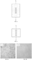
- milled PAN-based carbon fibers (150 ⁇ m length) were randomly distributed in water and observed under a microscope. This is shown in Fig. 5A .
- the same sample was agitated and placed under a permanent rare earth magnet that had a surface magnetic field of 0. 1-0.3 T in strength.
- the milled carbon fibers were observed to become vertically aligned under the applied magnetic field. To clarify, these milled carbon fibers did not contain any surface coatings. While the sample exposed to the magnetic field, it was observed under a microscope. An image of the milled carbon fibers vertically aligned in the water is shown in Fig. 5B , showing that some alignment had occurred.
Landscapes
- Engineering & Computer Science (AREA)
- Chemical & Material Sciences (AREA)
- Composite Materials (AREA)
- Mechanical Engineering (AREA)
- Textile Engineering (AREA)
- Materials Engineering (AREA)
- Chemical Kinetics & Catalysis (AREA)
- Medicinal Chemistry (AREA)
- Polymers & Plastics (AREA)
- Organic Chemistry (AREA)
- Health & Medical Sciences (AREA)
- Manufacturing & Machinery (AREA)
- Inorganic Chemistry (AREA)
- Inorganic Fibers (AREA)
- Reinforced Plastic Materials (AREA)
- Woven Fabrics (AREA)
- Compositions Of Macromolecular Compounds (AREA)
- Moulding By Coating Moulds (AREA)
Description
- The present invention generally relates to fiber-reinforced composites, including carbon-fiber composites.
- Fiber-reinforced composites (e.g. carbon fiber composites) feature a generally planar assembly of reinforcing fibers (e.g. carbon fibers) that are formed into woven or non-woven textile layers. These layers provide mechanical, thermal, and electrical performance in the direction of the strong-axis of the reinforcing fibers (e.g. in-plane), but have diminished performance when loads are applied transverse to the fibers (e.g. through-thickness). Most commonly available layer materials are comprised of planar assemblies of reinforcing fibers and offer limited through-thickness reinforcement.
- Typical fiber-reinforced composite structures feature several reinforcing fiber layers that are laminated and bonded together with a polymeric, ceramic, or metal matrix. While the anisotropic behavior of the reinforcing fibers provides the component with excellent in-plane properties, the lack of through-thickness reinforcement makes the laminated composite structure susceptible to interlaminar cracking, through-ply fractures, and thermal or electrical gradients. Ultimately, the lack of through-thickness reinforcement can lead to accelerated and catastrophic degradation of the laminated composite structure's integrity.
- One way to improve the through-thickness properties of laminated composite structures is to magnetically align carbon fibers in the through-thickness direction. In this process, discontinuous carbon fibers are surface-coated with magnetic particles (e.g. iron oxide nanoparticles). These magnetic particle surface-coated carbon fibers exhibit a physical response to magnetic fields and are assembled into fiber-reinforced composites with through-thickness reinforcement. However, the magnetic particles may increase the cost of these materials, potentially making them impractical in certain cost-sensitive manufacturing applications. Therefore, there exists a need to develop a process in which carbon fibers could be magnetically aligned to form fiber-reinforced composites with enhanced direction-dependent properties without the use of magnetic particle surface-coatings
- The present invention generally relates to fiber-reinforced composites, including carbon-fiber composites.
- Tus, the present invention provides an article comprising a composite comprising a plurality of continuous fibers defining a substrate, and a plurality of aligned carbon fibers contained within at least a portion of the substrate, wherein the carbon fibers comprise ≥ 40% of the mass of the composite, wherein the plurality of carbon fibers has a carbon content > 94% and a modulus of ≥ 200 GPa, and wherein the composite is free of paramagnetic or ferromagnetic materials.
- Also, the invention provides a method, comprising exposing a liquid comprising a plurality of carbon fibers having a carbon content > 94% and a modulus of ≥ 200 GPa to a plurality of continuous fibers defining a substrate, applying a magnetic field to the liquid to cause alignment of at least some of the carbon fibers within the plurality of continuous fibers, and forming a composite comprising the aligned carbon fibers, wherein the carbon fibers comprise ≥ 40% of the mass of the composite.
- Preferred embodiments of the invention are as defined in the appended dependent claims and/or in the following detailed description.
- Other advantages and novel features of the present invention will become apparent from the following detailed description of various non-limiting embodiments of the invention when considered in conjunction with the accompanying figures.
- Non-limiting embodiments of the present invention will be described by way of example with reference to the accompanying figures, which are schematic and are not intended to be drawn to scale. In the figures, each identical or nearly identical component illustrated is typically represented by a single numeral. For purposes of clarity, not every component is labeled in every figure, nor is every component of each embodiment of the invention shown where illustration is not necessary to allow those of ordinary skill in the art to understand the invention. In the figures:
-
Fig. 1 illustrates a relationship between fiber orientation and the principal stress direction in carbon fibers, in accordance with one embodiment of the invention; -
Fig. 2 illustrates shear-lag theory, in accordance with certain embodiments of the invention; -
Fig. 3 illustrates load transfer dominated by shear stresses, in another embodiment; and -
Fig. 4 shows that discontinuous fibers may have high modulus and may not undergo significant strain under loadings, minimizing the effect of shearing load transfer, according to certain embodiments of the invention; and -
Figs. 5A-5B illustrate aligned fibers, in one embodiment of the invention. - The present invention generally relates to fiber-reinforced composites, including carbon-fiber composites. These materials are useful in load-bearing components for mechanical systems, and other applications. Surprisingly, the carbon fibers can be aligned using an applied magnetic field applied directly to the carbon fibers, rather than to magnetic materials that are used to indirectly align the carbon fibers. For example, the carbon fibers may exhibit an anisotropic diamagnetic response in response to a magnetic field, which can be used to align the fibers. In some cases, the carbon fibers may be relatively pure, and/or have a relatively high modulus, which may result in diamagnetic properties. Other embodiments are generally directed to e.g. systems and methods for making or using such composites, or kits involving such composites.
- For example, certain aspects are generally directed to fiber-reinforced composite materials that features planar reinforcing fibers augmented with carbon fibers in the through-thickness direction. The through-thickness oriented carbon fibers may be captivated by sterics and optional binders. Alignment of carbon fibers transverse to the planar reinforcing fibers can eliminate interlaminar cracking, through-ply fractures, and thermal or electrical gradients. For example, the discontinuous carbon fibers may be aligned transverse to a layer of planar reinforcing fibers using low-energy magnetic fields (e.g. < 150 mT).
- One set of embodiments is generally directed to processes in which diamagnetic carbon fibers can be utilized to produce a fiber-reinforced composite that features discontinuous carbon fibers aligned transverse to a layer of planar reinforcing fibers. The use of diamagnetic carbon fibers may reduce or eliminate the need to utilize carbon fibers surface-coated with e.g. magnetic particles. In some embodiments, the discontinuous carbon fibers may have greater than 94% carbon content, and/or may exhibit highly-oriented molecular structures that are sufficiently diamagnetic to orient using low-energy magnetic fields (e.g., < 150 mT). Non-limiting examples of carbon fibers include, for instance, pitch- and/or polymer-based (e.g. ex-PAN or ex-Rayon) variants, including those commercially-available. In some cases, these may include intermediate/standard modulus (> 200 GPa) carbon fibers, high modulus (> 300 GPa), or ultra-high modulus (> 500 GPa) carbon fibers.
- In one aspect, the present invention concerns systems and methods for using a magnetic field to align carbon fibers, such as those discussed herein. The carbon fibers may be aligned directly via magnetic field, instead of using magnetic materials that are used to indirectly align the carbon fibers. The carbon fibers may be embedded within a composite, or used in other applications.
- Surprisingly, some types of carbon fibers are diamagnetic, and can be directly moved using an applied magnetic field. In contrast, most systems for aligning carbon fibers using magnetic fields use magnetic agents, such as magnetic particles, to indirectly cause the carbon fibers to align. Accordingly, it would not have been expected that carbon fibers that are free of paramagnetic or ferromagnetic materials could still be aligned using an external magnetic field. For example, if any paramagnetic or ferromagnetic materials are present, they may form < 5%, < 1%, < 0.5%, < 0.3%, < 0.1%, < 0.05%, < 0.03%, < 0.01%, < 0.005%, < 0.003%, or < 0.001% (by mass) of the material.
- In one set of embodiments, the carbon fibers have a relatively high carbon content. Without wishing to be bound by any theory, it is believed that such fibers may exhibit diamagnetic properties that allows them to be oriented with low-energy magnetic fields. In general, diamagnetism is the repulsion of a material to an applied magnetic field by generation of an induced magnetic field that is opposite in direction to the applied magnetic field. A material is typically categorized as diamagnetic if it lacks noticeable paramagnetic or ferromagnet contributions to the overall magnetic response. In many cases, the magnetic response of diamagnetic materials is very weak and negligible. However, relatively high magnetic fields can induce a noticeable physical response in such diamagnetic materials.
- Thus, in some cases, carbon fibers exhibiting relatively highly-oriented molecular structures may exhibit anisotropic, high-diamagnetism diamagnetic properties. Such diamagnetic properties may allow them to be oriented with relatively weak magnetic fields, such as is described herein. For example, in one set of embodiments, an applied magnetic field may generate a strong induced magnetic field in the C-C bonds of a carbon fiber in the opposite direction of the applied magnetic field. Certain types of carbon fibers may possess a high degree of C-C bonds parallel to the in-fiber direction, which may create an anisotropic diamagnetic response. Thus, such carbon fibers can be subjected to a magnetic torque that is neutralized when the carbon fiber aligns fully-parallel to the applied magnetic field. Accordingly, by applying a suitable magnetic field, the carbon fibers may be aligned due to such diamagnetic properties. This response may be sufficient to overcome gravitational, viscous, and/or interparticle steric effects.
- For instance, in certain embodiments, the carbon fibers have a carbon content greater than 94%, and may have a carbon content greater than 95%, greater than 96%, greater than 97%, greater than 98% greater than 99%, or greater than 99.5% by mass.
- Such carbon fibers may be obtained commercially in some cases. For example, the carbon fibers may be produced pyrolytically e.g., by "burning" or oxidizing other components that can be removed (e.g., by turning into a gas), leaving behind a carbon fiber with a relatively high carbon content. Other methods of making carbon fibers are also possible, e.g., as discussed in detail herein.
- The carbon fibers may also exhibit substantial alignment of the C-C bonds within the carbon fibers in some instances. For instance, >_ 50%, >_ 60%, >_ 70%, >_ 75%, >_ 80%, >_ 85%, >_ 90%, or ≥ 95% of the carbon fibers may exhibit substantial alignment of the C-C bonds. Such alignment may be determined, for example, using wide angle x-ray diffraction (WAXD), or other techniques known to those of ordinary skill in the art.
- In one set of embodiments, the carbon fibers may have a relatively high modulus (tensile modulus, which is a measure of stiffness). Typically, higher modulus fibers are stiffer and lighter than low modulus fibers. Carbon fibers typically have a higher modulus when force is applied parallel to the fibers, i.e., the carbon fibers are anisotropic. In some embodiments, the carbon fibers may have a modulus (e.g., when force is applied parallel to the fibers) of ≥ 100 GPa, ≥ 200 GPa, ≥ 300 GPa, ≥ 400 GPa, ≥ 500 GPa, ≥ 600 GPa, or ≥ 700 GPa. It is believed that more flexible carbon fibers may exhibit less alignment, i.e., carbon fibers having a low modulus may have subtle physical responses to magnetic fields, or have no response, rather than align within an applied magnetic field.
- In one set of embodiments, the carbon fibers may exhibit an anisotropic diamagnetic response when free-floating within a liquid (e.g., water, oil, polymer resin, polymer melt, metal melt, an alcohol such as ethanol, or another volatile organic compound), and a magnetic field is applied. For example, in some cases, the carbon fibers may align when a suitable magnetic field is applied, i.e., indicative of a diamagnetic response. In some cases, the magnetic field may be ≥ 100 mT, ≥ 200 mT, ≥ 300 mT, ≥ 500 mT, ≥ 750 mT, ≥ 1 T, ≥ 1.5 T, ≥ 2 T, ≥ 3 T, ≥ 4 T, or ≥ 5 T. In some cases, >_ 30%, >_ 40%, ≥ 50%, >_ 60%, >_ 70%, >_ 80%, or ≥ 90%, of the free-floating carbon fibers within the liquid may exhibit alignment when a suitable magnetic field is applied.
- Typically, a carbon fiber has a shape such that one orthogonal dimension (e.g., its length) is substantially greater than its other two orthogonal dimensions (e.g., its width or thickness). The fiber may be substantially cylindrical in some cases. As mentioned, the carbon fibers may be relatively stiff, in some instances; however, a carbon fiber need not be perfectly straight (e.g., its length may still be determined along the fiber itself, even if it is curved).
- In one set of embodiments, the carbon fiber may have a dimension (e.g., a characteristic dimension) that is substantially the same, or smaller, than the thickness of the substrate. For example, at least some carbon fibers within a composite may have an average length that substantially spans the thickness of the substrate. However, in other cases, the characteristic dimension of the carbon fiber may be greater than the thickness.
- As mentioned, certain embodiments of the invention are generally directed to composites comprising carbon fibers. In some cases, the carbon fibers within a composite may have an average length, or characteristic dimension, of ≥ 1 nm, ≥ 3 nm, ≥ 5 nm, ≥ 10 nm, ≥ 30 nm, ≥ 50 nm, ≥ 100 nm, ≥ 300 nm, ≥ 500 nm, ≥ 1 µm, ≥ 3 µm, ≥ 5 µm, ≥ 10 µm, ≥ 20 µm, ≥ 30 µm, ≥ 50 µm, ≥ 100 µm, ≥ 200 µm, ≥ 300 µm, ≥ 500 µm, ≥ 1 mm, ≥ 2 mm, ≥ 3 mm, ≥ 5 mm, ≥ 1 cm, ≥ 1.5 cm, ≥ 2 cm, ≥ 3 cm, ≥ 5 cm, or ≥ 10 cm. In certain embodiments, the carbon fibers may have an average length, or characteristic dimension, of ≤ 10 cm, ≤ 5 cm, ≤ 3 cm, ≤ 2 cm, ≤ 1.5 cm, ≤ 1 cm, ≤ 5 mm, ≤ 3 mm, ≤ 2 mm, ≤ 1 mm, ≤ 500 µm, ≤ 300 µm, ≤ 200 µm, ≤ 100 µm, ≤ 50 µm, ≤ 30 µm, ≤ 20 µm, ≤ 10 µm, ≤ 5 µm, ≤ 3 µm, ≤ 1 µm, ≤ 500 nm, ≤ 300 nm, ≤ 100 nm, ≤ 50 nm, ≤ 30 nm, ≤ 10 nm, or ≤ 5 nm. Combinations of any of these are also possible. For example, the carbon fibers within a composite may have an average length of 5-15 mm, or 1-5 mm, or 1-1 cm.
- In addition, the carbon fibers may also have any suitable average diameter. For instance, the carbon fibers may have an average diameter of ≥ 10 µm, ≥ 20 µm, ≥ 30 µm, ≥ 50 µm, ≥ 100 µm, ≥ 200 µm, ≥ 300 µm, ≥ 500 µm, ≥ 1 mm, ≥ 2 mm, ≥ 3 mm, ≥ 5 mm, ≥ 1 cm, ≥ 2 cm, ≥ 3 cm, ≥ 5 cm, or ≥ 10 cm. In certain embodiments, the carbon fibers may have an average diameter of ≤ 10 cm, ≤ 5 cm, ≤ 3 cm, ≤ 2 cm, ≤ 1 cm, ≤ 5 mm, ≤ 3 mm, ≤ 2 mm, ≤ 1 mm, ≤ 500 µm, ≤ 300 µm, ≤ 200 µm, ≤ 100 µm, ≤ 50 µm, ≤ 30 µm, ≤ 20 µm, or ≤ 10 µm. Combinations of any of these are also possible. For example, the carbon fibers may have an average diameter of 5-100 µm, 10-100 µm, 50-500 µm, or100 µm to 5 mm.
- In certain embodiments, the carbon fibers may have a length that is >_ 10 times or ≥ 50 times its thickness or diameter, on average. In some cases, the fibers within a composite may have an average aspect ratio (ratio of fiber length to diameter or thickness) of ≥ 3, ≥ 5, ≥ 10, ≥ 30, ≥ 50, ≥ 100, ≥ 300, ≥ 500, ≥ 1,000, ≥ 3,000, ≥ 5,000, ≥ 10,000, ≥ 30,000, ≥ 50,000, or ≥ 100,000. In some cases, the average aspect ratio may be < 100,000, < 50,000, < 30,000, < 10,000, < 5,000, < 3,000, < 1,000, < 500, < 300, < 100, < 50, < 30, < 10, or < 5. Combinations of any of these are also possible in some cases; for instance, the aspect ratio may be 5-100,000.
- The carbon fibers comprise ≥ 40% of the mass of the composite. For example, the carbon fibers may comprise at ≥ 45%, ≥ 50%, ≥ 55%, ≥ 60%, ≥ 65%, ≥ 70%, ≥ 75%, ≥ 80%, > 85%, >_ 90%, >_ 95%, or ≥ 97% of the mass of the composite. In some cases, the carbon fibers comprise ≤ 97%, ≤ 95%, ≤ 90%, ≤ 85%, ≤ 80%, ≤ 70%, ≤ 60%, or ≤ 50% of the mass of the composite. Combinations of any of these are also possible.
- The carbon fibers, in some embodiments, may be at least substantially aligned within the composite. Methods for aligning carbon fibers are discussed in more detail herein. Various alignments are possible, and in some cases, can be determined optically or microscopically, e.g. Thus, in some cases, the alignment may be determined qualitatively. However, it should be understood that the alignment need not be perfect. In some cases, >_ 5%, > 10%, > 25%, > 50%, >_ 75%, >_ 85%, >_ 90%, or ≥ 95% of the carbon fibers within a composite may exhibit an alignment that is within 20°, within 15°, within 10°, or within 5° of the average alignment of the plurality of the carbon fibers, e.g., within a sample of the composite.
- In certain instances, the alignment of the carbon fibers is substantially orthogonal to the substrate. For example, the average alignment may be oriented to be ≥ 60°, ≥ 65°, ≥ 70°, ≥ 75°, ≥ 85°, or ≥ 87° relative to the plane of the substrate at that location. As mentioned, the substrate itself may not necessarily be planar, but may also be e.g. curved.
- Without wishing to be bound by any theory, it is believed that alignment of the carbon fibers substantially orthogonal to the substrate may serve to provide reinforcement of the substrate. This may improve the strength of the substrate, e.g., when subjected to forces in different directions. For instance, fibers within the substrate may run in substantially orthogonal directions in 3 dimensions, thereby providing strength to the substrate regardless of the direction of force that is applied. The carbon fibers may also limit degradation of the surface, e.g., with interlaminar micro-cracks, or through-ply fissures. In addition, in some embodiments, the carbon fibers may enhance other properties of the substrate, e.g., electrical and/or thermal properties within the composite, in addition to or instead of its mechanical properties.
- A variety of carbon fibers may be obtained commercially, including diamagnetic carbon fibers. In some cases, carbon fibers can be produced from polymer precursors such as polyacrylonitrile (PAN), rayon, or pitch. In some cases, carbon fibers can be spun into filament yarns, e.g., using chemical or mechanical processes to initially align the polymer atoms in a way to enhance the final physical properties of the completed carbon fibers. Precursor compositions and mechanical processes used during spinning filament yarns may vary. After drawing or spinning, the polymer filament yarns can be heated to drive off non-carbon atoms (carbonization or pyrolization), to produce final carbon fiber. In some embodiments, such techniques may be used to produce carbon fiber with relatively high carbon content, e.g., ≥ 90%, or other contents as described herein.
- At least some or all of the carbon fibers may be uncoated. In some cases, however, some or all of the carbon fibers may be coated. As non-limiting examples, the carbon fibers may be coated with a surfactant, a silane coupling agent, an epoxy, glycerine, polyurethane, an organometallic coupling agent, a polymer, a ceramic, or a metal. Non-limiting examples of surfactants include oleic acid, sodium dodecyl sulfate, and sodium lauryl sulfate. Non-limiting examples of silane coupling agents include amino-, benzylamino-, chloropropyl-, disulfide-, epoxy-, epoxy/melamine-, mercapto-, methacrylate-, tertasulfido-, ureido-, vinyl-, isocynate-, and vinly-benzyl-amino-based silane coupling agents. Non-limiting examples of organometallic coupling agents include aryl- and vinyl-based organometallic coupling agents
- In addition, certain aspects of the invention are generally directed to composites comprising a plurality of continuous fibers defining a substrate, and a plurality of carbon fibers contained within the substrate, as noted above. For instance, at least some of the plurality of carbon fibers may be contained within holes, interstitials, or pores of the substrate, e.g., created by spacing between the continuous fibers that define the substrate. In some cases, the carbon fibers may be substantially aligned within the holes, interstitials, or pores. In some embodiments, a binder may be present, for example, to bind the continuous fibers and/or the carbon fibers within the composite.
- In some cases, the composite is generally planar. However, it should be understood that such a substrate need not be a mathematically-perfect planar structure (although it can be); for instance, the substrate may also be deformable, curved, bent, folded, rolled, creased, or the like. In certain embodiments, the substrate may have an average thickness of ≥ 0.1 µm, ≥ 0.2 µm, ≥ 0.3 µm, ≥ 0.5 µm, ≥ 1 µm, ≥ 2 µm, ≥ 3 µm, ≥ 5 µm, ≥ 10 µm, ≥ 30 µm, ≥ 50 µm, ≥ 100 µm, ≥ 300 µm, ≥ 500 µm, ≥ 1 mm, ≥ 2 mm, ≥ 3 mm, ≥ 5 mm, ≥ 1 cm, ≥ 3 cm, ≥ 5 cm, ≥ 10 cm, ≥ 30 cm, ≥ 50 cm, or ≥ 100 cm. In certain instances, the average thickness may be < 100 cm, < 50 cm, < 30 cm, < 10 cm, < 5 cm, < 3 cm, < 1 cm, < 5 mm, < 2 mm, < 3 mm, < 1 mm, < 500 µm, < 300 µm, < 100 µm, < 50 µm, < 30 µm, < 10 µm, < 5 µm, < 3 µm, less than 1 µm, less than 0.5 µm, < 0.3 µm, or < 0.1 µm. Combinations of any of these are also possible in certain embodiments. For instance, the average thickness may be 0.1-5,000 µm, 10-2,000 µm, or 50-1,000 µm. The thickness may be uniform or non-uniform across the substrate. Also, the substrate may be rigid (e.g., as discussed herein), or may be deformable in some cases.
- In some cases, the pores, interstitials, or holes that are created by the continuous fibers may be relatively small. Some or all of the pores, interstitials, or holes may contain carbon fibers, which may be aligned in some cases, e.g., as discussed herein. The pores, interstitials, or holes may have an average size or cross-sectional dimension of ≤ 10 cm, ≤ 5 cm, ≤ 3 cm, ≤ 2 cm, ≤ 1 cm, ≤ 5 mm, ≤ 3 mm, ≤ 2 mm, ≤ 1 mm, ≤ 500 µm, ≤ 300 µm, ≤ 200 µm, ≤ 100 µm, ≤ 50 µm, ≤ 30 µm, ≤ 20 µm, or ≤ 10 µm.
- Composites may be used in a wide variety of applications, including those discussed in more detail herein. As non-limiting examples, composites may be used in diverse applications such as reinforcement for pressure vessels, components for wind turbines, shims used in jacking heavy structures, sporting equipment, building or construction materials, laminates or encapsulants for electronic devices, battery components, bearings, or panels for vehicles such as automobiles, aircraft, marine vehicles, or spacecraft.
- As mentioned, one set of embodiments of the invention are generally directed to composites comprising substrates formed from continuous fibers, and containing a plurality of carbon fibers. The continuous fibers generally have a length that on average is substantially longer than the characteristic dimension of the carbon fibers. For instance, the continuous fibers may have an average length that is > 10, > 30, > 50, > 100, > 300, > 500, or > 1,000 times the characteristic dimension of the carbon fibers. In some embodiments, the continuous fibers have an average aspect ratio (e.g., of length to diameter or average cross-sectional dimension) of ≥ 3, ≥ 5, ≥ 10, ≥ 30, ≥ 50, ≥ 100, ≥ 300, ≥ 500, or ≥ 1,000. Additionally, in certain cases, the continuous fibers may have an average length of ≥ 1 nm, ≥ 3 nm, ≥ 5 nm, ≥ 10 nm, ≥ 30 nm, ≥ 50 nm, ≥ 100 nm, ≥ 300 nm, ≥ 500 nm, ≥ 1 µm, ≥ 3 µm, ≥ 5 µm, ≥ 10 µm, ≥ 30 µm, ≥ 50 µm, ≥ 100 µm, ≥ 300 µm, ≥ 500 µm, ≥ 1 mm, ≥ 3 mm, ≥ 5 mm, ≥ 1 cm, ≥ 3 cm, ≥ 5 cm, or ≥ 10 cm. Longer average lengths are also possible in some instances.
- The continuous fibers may be woven together (e.g. bidirectional, multidirectional, or quasi-isotropic), and/or non-woven (e.g., unidirectional, veil, or mat). In certain embodiments, at least some of the continuous fibers are substantially parallel, and/or orthogonally oriented relative to each other, although other configurations of continuous fibers are also possible. In certain embodiments, the continuous fibers may together define a fabric or other substrate, e.g., a textile, a tow, a filament, a yarn, a strand, or the like. In some cases, the substrate may have one orthogonal dimension that is substantially less than the other orthogonal dimensions (i.e., the substrate may have a thickness).
- The continuous fibers forming the substrate may comprise any of a wide variety of materials, and one type or more than one type of fiber may be present within the substrate. Non-limiting examples include carbon, basalt, silicon carbide, aramid, zirconia, nylon, boron, alumina, silica, borosilicate, mullite, cotton, or any other natural or synthetic fibers.
- The continuous fibers may have any suitable average diameter. For example, the continuous fibers may have an average diameter of ≥ 10 µm, ≥ 20 µm, ≥ 30 µm, ≥ 50 µm, ≥ 100 µm, ≥ 200 µm, ≥ 300 µm, ≥ 500 µm, ≥ 1 mm, ≥ 2 mm, ≥ 3 mm, ≥ 5 mm, ≥ 1 cm, ≥ 2 cm, ≥ 3 cm, ≥ 5 cm, or ≥ 10 cm. In certain embodiments, the continuous fibers may have an average diameter of ≤ 10 cm, ≤ 5 cm, ≤ 3 cm, ≤ 2 cm, ≤ 1 cm, ≤ 5 mm, ≤ 3 mm, ≤ 2 mm, ≤ 1 mm, ≤ 500 µm, ≤ 300 µm, ≤ 200 µm, ≤ 100 µm, ≤ 50 µm, ≤ 30 µm, ≤ 20 µm, or ≤ 10 µm. Combinations of any of these are also possible. For example, the continuous fibers may have an average diameter of 5-100 µm, 10-100 µm, 50-500 µm, or 100-µm to 5 mm.
- The continuous fibers may also have any suitable average length. For example, the continuous fibers may have an average length of ≥ 0.5 cm, ≥ 1 cm, ≥ 2 cm, ≥ 3 cm, ≥ 5 cm, or ≥ 10 cm. In certain embodiments, the continuous fibers may have an average diameter of ≤ 10 cm, ≤ 5 cm, ≤ 3 cm, ≤ 2 cm, ≤ 1 cm, or ≤ 0.5 cm. Combinations of any of these are also possible; for example, the continuous fibers may have an average length of 1-10 cm, or 10-100 cm.
- In some instances, the continuous fibers may comprise a relatively large portion of the composite. For example, in certain embodiments, the continuous fibers may comprise ≥ 1%, ≥ 2%, ≥ 3%, ≥ 4%, ≥ 5%, ≥ 7%, ≥ 10%, ≥ 15%, ≥ 20%, ≥ 25%, ≥ 30%, ≥ 35%, ≥ 40%, > 45%, >_ 50%, or ≥ 55%, of the mass of the composite. In some cases, the continuous fibers ≤ 50%, <_ 40%, <_ 30%, <_ 20%, or ≤ 10% of the mass of the composite. Combinations of any of these are also possible.
- The composite may also contain one or more discontinuous agents in certain embodiments, e.g., in addition to carbon fibers. The discontinuous agents may include agglomerated agents or individual agents. The agents may have a variety of shapes, including fibers or platelets. Other shapes include, but are not limited to, nanotubes, nanofibers, nanosheets, or the like. In one set of embodiments, the discontinuous agents are not spherical. A fiber may have a shape such that one orthogonal dimension (e.g., its length) is substantially greater than its other two orthogonal dimensions (e.g., its width or thickness). A platelet may have a shape such that two orthogonal dimensions (e.g., its diameter) are substantially greater than its other orthogonal dimension (e.g., its width or thickness). A platelet may be substantially cylindrical or disc-shaped in some cases, although it may have other shapes as well. In addition, it should be understood that both platelets and fibers may be present in some cases, and/or that other shapes may be present in certain embodiments (e.g., instead of or in addition to platelets and/or fibers).
- It should be understood that discontinuous agents such as platelets and/or fibers may be relatively stiff, or may be curved or flexible in some cases, or adopt a variety of other shapes. For instance, a fiber need not be perfectly straight, or a platelet need not be perfectly disc-shaped.
- As mentioned, certain embodiments of the invention are generally directed to composites comprising discontinuous fibers. In some cases, the discontinuous fibers within a composite may have an average length, or characteristic dimension, of ≥ 1 nm, ≥ 3 nm, ≥ 5 nm, ≥ 10 nm, ≥ 30 nm, ≥ 50 nm, ≥ 100 nm, ≥ 300 nm, ≥ 500 nm, ≥ 1 µm, ≥ 3 µm, ≥ 5 µm, ≥ 10 µm, ≥ 20 µm, ≥ 30 µm, ≥ 50 µm, ≥ 100 µm, ≥ 200 µm, ≥ 300 µm, ≥ 500 µm, ≥ 1 mm, ≥ 2 mm, ≥ 3 mm, ≥ 5 mm, ≥ 1 cm, ≥ 1.5 cm, ≥ 2 cm, ≥ 3 cm, ≥ 5 cm, or ≥ 10 cm. In certain embodiments, the discontinuous fibers may have an average length, or characteristic dimension, of ≤ 10 cm, ≤ 5 cm, ≤ 3 cm, ≤ 2 cm, ≤ 1.5 cm, ≤ 1 cm, ≤ 5 mm, ≤ 3 mm, ≤ 2 mm, ≤ 1 mm, ≤ 500 µm, ≤ 300 µm, ≤ 200 µm, ≤ 100 µm, ≤ 50 µm, ≤ 30 µm, ≤ 20 µm, ≤ 10 µm, ≤ 5 µm, ≤ 3 µm, ≤ 1 µm, ≤ 500 nm, ≤ 300 nm, ≤ 100 nm, ≤ 50 nm, ≤ 30 nm, ≤ 10 nm, or ≤ 5 nm. Combinations of any of these are also possible. For example, the discontinuous fibers within a composite may have an average length of 5-15 mm, or 1-5 mm, or 1 mm to 1 cm.
- In addition, the discontinuous fibers may also have any suitable average diameter. For instance, the discontinuous fibers may have an average diameter of ≥ 10 µm, ≥ 20 µm, ≥ 30 µm, ≥ 50 µm, ≥ 100 µm, ≥ 200 µm, ≥ 300 µm, ≥ 500 µm, ≥ 1 mm, ≥ 2 mm, ≥ 3 mm, ≥ 5 mm, ≥ 1 cm, ≥ 2 cm, ≥ 3 cm, ≥ 5 cm, or ≥ 10 cm. In certain embodiments, the discontinuous fibers may have an average diameter of ≤ 10 cm, ≤ 5 cm, ≤ 3 cm, ≤ 2 cm, ≤ 1 cm, ≤ 5 mm, ≤ 3 mm, ≤ 2 mm, ≤ 1 mm, ≤ 500 µm, ≤ 300 µm, ≤ 200 µm, ≤ 100 µm, ≤ 50 µm, ≤ 30 µm, ≤ 20 µm, or ≤ 10 µm. Combinations of any of these are also possible. For example, the discontinuous fibers may have an average diameter of 10-100 µm, 50-500 µm, or 100 µm to 5 mm.
- In certain embodiments, the discontinuous fibers may have a length that is ≥ 10 times or ≥ 50 times its thickness or diameter, on average. In some cases, the fibers within a composite may have an average aspect ratio (ratio of fiber length to diameter or thickness) of ≥ 3, ≥ 5, ≥ 10, ≥ 30, ≥ 50, ≥ 100, ≥ 300, ≥ 500, ≥ 1,000, ≥ 3,000, ≥ 5,000, ≥ 10,000, ≥ 30,000, ≥ 50,000, or ≥ 100,000. In some cases, the average aspect ratio may be < 100,000, < 50,000, < 30,000, < 10,000, < 5,000, < 3,000, < 1,000, < 500, < 300, < 100, < 50, < 30, < 10, or < 5. Combinations of any of these are also possible in some cases; for instance, the aspect ratio may be 5-100,000.
- As mentioned, the composite is not limited to only discontinuous fibers. In certain embodiments, a composite may include platelets, e.g., instead of or in addition to discontinuous fibers. Typically, a platelet may be disc-shaped, although other shapes may be possible as well.
- In some cases, the platelet may have a maximum dimension or a characteristic dimension of ≥ 10 µm, ≥ 20 µm, ≥ 30 µm, ≥ 50 µm, ≥ 100 µm, ≥ 200 µm, ≥ 300 µm, ≥ 500 µm, ≥ 1 mm, ≥ 2 mm, ≥ 3 mm, ≥ 5 mm, ≥ 1 cm, ≥ 1.5 cm, ≥ 2 cm, ≥ 3 cm, ≥ 5 cm, or ≥ 10 cm. In certain embodiments, the platelet have a maximum dimension or a characteristic dimension of ≤ 10 cm, ≤ 5 cm, ≤ 3 cm, ≤ 2 cm, ≤ 1.5 cm, ≤ 1 cm, ≤ 5 mm, ≤ 3 mm, ≤ 2 mm, ≤ 1 mm, ≤ 500 µm, ≤ 300 µm, ≤ 200 µm, ≤ 100 µm, ≤ 50 µm, ≤ 30 µm, ≤ 20 µm, or ≤ 10 µm. If the platelet does not have a substantially circular face (for example, if the platelet has an oblong or an irregular face), then the characteristic dimension may be taken as a diameter of a perfect circle having the same area as the face of the platelet. Combinations of any of these dimensions are also possible. For example, the maximum dimension or a characteristic dimension may be 5-15 mm, or 1-5 mm, or 1 mm to 1 cm.
- In certain embodiments, the platelet may have an average aspect ratio (ratio of largest dimension to smallest dimension or thickness) of ≥ 3, ≥ 5, ≥ 10, ≥ 30, ≥ 50, ≥ 100, ≥ 300, ≥ 500, or ≥ 1,000. In some cases, the average aspect ratio may be < 1,000, < 500, < 300, < 100, < 50, < 30, < 10, or < 5. Combinations of any of these are also possible in some cases; for instance, the aspect ratio may be 5-1,000.
- The discontinuous agents may be formed or include any of a wide variety of materials, and one or more than one type of material may be present. For example, the discontinuous agents may comprise materials such as basalt, silicon carbide, silicon nitride, aramid, zirconia, nylon, boron, alumina, silica, borosilicate, mullite, nitride, boron nitride, graphite, or glass. The discontinuous agents may include any natural and/or any synthetic material, and may be magnetic and/or non-magnetic.
- In certain embodiments, a binder is also present within the composite, e.g., which may be used to bind the continuous fibers and the carbon fibers (and optionally other materials). For example, the binder may facilitate holding the continuous fibers and the carbon fibers in position within the composite. However, it should be understood that the binder is optional and not required in all cases. In some cases, the binder may comprise a resin. The binder may include a thermoset or a thermoplastic. In certain embodiments, the binder may comprise a thermoplastic solution, a thermoplastic melt, thermoplastic pellets, thermoplastic powders, thermoplastic films, a thermoset resin, a volatile compound such as a volatile organic compound, water, or an oil. Additional non-limiting examples of binders include an epoxy, polyester, vinyl ester, polyethylenimine, polyetherketoneketone, polyaryletherketone, polyether ether ketone, polyphenylene sulfide, polyethylene terephthalate, a polycarbonates, poly(methyl methacrylate), acrylonitrile butadiene styrene, polyacrylonitrile, polypropylene, polyethylene, nylon, a silicone rubber, polyvinylidene fluoride, polytetrafluoroethylene, perfluoroalkoxy alkanes, styrene butadiene rubber, or a pre-ceramic monomer, such as a siloxane, a silazane, or a carbosilane. The binder may also include mixtures including any one or more of these materials and/or other materials, in certain embodiments.
- In some embodiments, the binder may comprise ≥ 1%, >_ 2%, >_ 3%, >_ 4%, >_ 5%, >_ 7%, > 10%, > 15%, > 20%, or ≥ 25% of the mass of the composite, and/or ≤ 25%, ≤ 20%, ≤ 15%, <_ 10%, <_ 7%, <_ 5%, ≤ 4%, ≤ 3%, ≤ 2%, or ≤ 1% of the mass of the composite.
- Another aspect of the present invention is generally directed to systems and methods for making composites such as those described herein. In one set of embodiments, composites can be prepared from a liquid, such as a slurry, containing a plurality of carbon fibers, to which a suitable substrate is exposed to. A magnetic field can be applied to manipulate the carbon fibers, e.g., when such carbon fibers exhibit an anisotropic diamagnetic response in response to the magnetic field. Excess material can be removed. In some cases, the composite can be set or hardened, e.g., with a binder, which may be used to immobilize or fix the carbon fibers within the substrate. The binder may, in certain embodiments, be infused or impregnated into the substrate.
- In some cases, a liquid, such as a slurry, may be formed. The slurry may include carbon fibers. The liquid phase may include, for example, a thermoplastic or a thermoset, e.g., a thermoplastic solution, thermoplastic melt, thermoplastic pellet, thermoplastic powder, thermoset resin, thermoset emulsion, thermoset powder, volatile organic compound, water, or oil. Non-limiting examples of thermoplastics include polyethylenimine, polyetherketoneketone, polyaryletherketone, polyether ether ketone, polyphenylene sulfide, polyethylene terephthalate, a polycarbonates, poly(methyl methacrylate), acrylonitrile butadiene styrene, polyacrylonitrile, polypropylene, polyethylene, nylon, polyvinylidene fluoride, phenolics, epoxies, bismaleimides, cyanate esters, and polyimides. Non-limiting examples of elastomers include silicone rubber and styrene butadiene rubber. Non-limiting examples of thermosets include epoxy, polyester, and vinyl ester. Non-limiting examples of pre-ceramic monomers include a siloxane, a silazane, or a carbosilane. In some cases, for example, one or more of these may be added to assist in homogenously dispersing the carbon fibers within the liquid. Examples of volatile organic compounds include, but are not limited to, water, isopropanol, butanol, ethanol, acetone, toluene, or xylenes. Particles may also be present within the slurry in some cases, e.g., polymer particles, ceramic particles, and metal particles.
- Any suitable amount of carbon fiber may be present in the slurry or other liquid. For instance, >_ 10%, > 15%, > 20%, > 25%, >_ 30%, >_ 35%, >_ 40%, > 45%, >_ 50%, >_ 55%, ≥ 60%, > 65%, >_ 70%, >_ 75%, or ≥ 80% of the volume of the slurry may be carbon fibers. In some cases, <_ 85%, <_ 80%, <_ 75%, <_ 70%, <_ 65%, <_ 60%, <_ 55%, <_ 50%, <_ 45%, <_ 40%, <_ 35%, <_ 30%, <_ 25%, <_ 20%, <_ 15%, or ≤ 10% may be carbon fibers. Combinations of any of these are also possible in some cases. For example, a slurry or other liquid may contain 70-80%, 75-85%, or 50-90% carbon fibers.
- After preparation of the slurry or other liquid, it may be applied to or exposed to the substrate, e.g., comprising the continuous fibers. In some cases, the substrate may be placed on a surface such as a polymer foil, metal foil, or paper, e.g., for application of liquid, a magnetic field, mechanical vibration, and/or heating, e.g., as discussed herein.
- Any suitable method may be used to apply the slurry or other liquid to the substrate. As non-limiting examples, the liquid may be poured, coated, sprayed, or painted onto the substrate, or the substrate may be immersed partially or completely within the liquid. The liquid may be used to wet, coat, and/or surround the continuous fibers.
- A magnetic field may be applied to manipulate the carbon fibers, e.g., via an anisotropic diamagnetic response. For instance, the magnetic field may be used to move the carbon fibers into the substrate, e.g., into pores, interstitials, or holes within the substrate. In addition, in some cases, the magnetic field may be used to ≥ substantially align the carbon fibers within the substrate, e.g., as discussed herein. For example, the magnetic field may be used to align ≥ 50%, ≥ 75%, ≥ 85%, ≥ 90%, or ≥ 95% of the carbon fibers to within 20°, within 15 °, within 10 °, or within 5 ° of the average alignment. The magnetic field, in some embodiments, may be used to align the carbon fibers within the substrate, e.g., in the direction of the magnetic field, and/or within the substrate in a through-plane direction.
- Any suitable magnetic field may be applied. In some cases, the magnetic field is a constant magnetic field. In other cases, the magnetic field may be time-varying; for example, the magnetic field may oscillate or periodically change in amplitude and/or direction, e.g., to facilitate manipulation of the carbon fibers. The oscillation may be sinusoidal or another repeating waveform (e.g., square wave or sawtooth). The frequency may be, for example, >_ 0.1 Hz, ≥ 0.3 Hz, ≥ 0.5 Hz, ≥ 1 Hz, ≥ 3 Hz, ≥ 5 Hz, ≥ 10 Hz, ≥ 30 Hz, ≥ 50 Hz, ≥ 100 Hz, ≥ 300 Hz, or ≥ 500 Hz, and/or ≤ 1000 Hz, ≤ 500 Hz, ≤ 300 Hz, ≤ 100 Hz, ≤ 50 Hz, ≤ 30 Hz, ≤ 10 Hz, ≤ 5 Hz, or ≤ 3 Hz. For example, the frequency may be 1-500 Hz, 10-30 Hz, or 50- Hz. In addition, the frequency may be held substantially constant, or the frequency may vary in some cases.
- The magnetic field, whether constant or oscillating, may have any suitable amplitude. For example, the amplitude may be ≥ 0.001 T, ≥ 0.003 T, ≥ 0.005 T, ≥ 0.01 T, ≥ 0.03 T, ≥ 0.05 T, ≥ 0.1 T, ≥ 0.3 T, ≥ 0.5 T, ≥ 1 T, ≥ 3 T, ≥ 5 T, or ≥ 10 T. The amplitude in some cases may be ≤ 20 T, ≤ 10 T, ≤ 5 T, ≤ 3 T, ≤ 1 T, ≤ 0.5 T, ≤ 0.3 T, ≤ 0.1 T, ≤ 0.05 T, ≤ 0.03 T, ≤ 0.01 T, ≤ 0.005 T, or ≤ 0.003 T. The amplitude may also fall within any combination of these values. For instance, the amplitude may be 0.01-10 T, 1-3 T, or 0.5-1 T. The amplitude may be substantially constant, or may vary in certain embodiments, e.g., within any range of these values.
- In some embodiments, the magnetic field direction (i.e., direction of maximum amplitude) may vary by +/- 90°, +/- 85°, +/- 80°, +/-75°, +/-70°, +/-65°, +/-60°, +/-55°, +/-50°, +/-45°, +/-40°, +/-35°, +/-30°, +/-25°, +/-20°, +/-15°, +/-10°, +/-5° about a mean direction.
- A variety of different devices for producing suitable magnetic fields may be obtained commercially, and include permanent magnets or electromagnets. In some cases, an oscillating magnetic may be created by attaching a magnet to a rotating disc and rotating the disc at an appropriate speed or frequency. Non-limiting examples of permanent magnets include iron magnets, alnico magnets, and rare earth magnets.
- In addition, in one set of embodiments, mechanical vibration may be used to manipulate the particles, e.g., in addition to and/or instead of magnetic manipulation. For example, mechanical vibration can be used to move particles into the substrate, e.g., into pores, interstitials, or holes within the substrate, and/or at least substantially align the carbon fibers within the substrate, e.g., as discussed herein. In some cases, vibration may be used to align the carbon fibers within the substrate and/or move the carbon fibers into holes, interstitials, or pores within the substrate.
- In one set of embodiments, mechanical vibration may be applied to cause motion of the carbon fibers of ≥ 1 µm, ≥ 2 µm, ≥ 3 µm, ≥ 5 µm, ≥ 10 µm, ≥ 20 µm, ≥ 30 µm, ≥ 50 µm, ≥ 100 µm, ≥ 200 µm, ≥ 300 µm, ≥ 500 µm, ≥ 1,000 µm, ≥ 2,000 µm, ≥ 3,000 µm, ≥ 5,000 µm, or≥ 10,000 µm.
- In addition, in some cases, the mechanical vibrations may be time-varying; for example, the mechanical vibrations may periodically change in amplitude and/or direction, e.g., to facilitate manipulation of the carbon fibers. The oscillation may be sinusoidal or another repeating waveform (e.g., square wave or sawtooth). The frequency may be, for example, >_ 0.1 Hz, ≥ 0.3 Hz, ≥ 0.5 Hz, ≥ 1 Hz, ≥ 3 Hz, ≥ 5 Hz, ≥ 10 Hz, ≥ 30 Hz, ≥ 50 Hz, ≥ 100 Hz, ≥ 300 Hz, or ≥ 500 Hz, and/or ≤ 1000 Hz, ≤ 500 Hz, ≤ 300 Hz, ≤ 100 Hz, ≤ 50 Hz, ≤ 30 Hz, ≤ 10 Hz, ≤ 5 Hz, or ≤ 3 Hz. For example, the frequency may be 1-500 Hz, 10-30 Hz, or 50- Hz. In addition, the frequency may be held substantially constant, or the frequency may vary in some cases. If applied in conjunction with an oscillating magnetic field, their frequencies may independently be the same or different.
- During and/or after alignment, the carbon fibers within the substrate may be set or fixed in some embodiments, e.g., to prevent or limit subsequent movement of the carbon fibers and form a relatively hard composite. Non-limiting examples of techniques to form the composite include, but are not limited to solidifying, hardening, gelling, melting, evaporating, freezing, or lyophilizing the liquid or the slurry. In another set of embodiments, a material, such as a thermosetting polymer, may be cured to harden the composite. The substrate may thus form a composite that is e.g. a solid or a gel.
- In some cases, the liquid may comprise a relatively volatile solvent, which can be removed by heating and/or evaporation (e.g., by waiting a suitable amount of time, or allowing the solvent to evaporate, e.g., in a fume hood or other ventilated area). Non-limiting examples of volatile solvents include isopropanol, butanol, ethanol, acetone, toluene, or xylenes. Other examples of methods of removing solvents include applying vacuum, lyophilization, or mechanical shaking.
- In one set of embodiments, heating may be applied to the substrate, for example, to remove a portion of the solvent. For example, the substrate may be heated to a temperature of ≥ 30°C, >_ 35°C, >_ 40°C, >_ 45°C, >_ 50°C, >_ 55°C, >_ 60°C, >_ 65°C, >_ 70°C, >_ 75°C, >_ 80°C, >_ 90°C, >_ 100°C, >_ 125°C, >_ 150°C, >_ 175°C, >_ 200°C, >_ 250°C, >_ 300°C, >_ 350°C, ≥ 400°C, >_ 450°C, or ≥ 500°C. Any suitable method of applying heat may be used, for example, a thermoelectric transducer, an Ohmic heater, a Peltier device, or a combustion heater. In some cases, the viscosity of the liquid may decrease as a result of heating. The heating may be applied, for example, prior, concurrent or subsequent to the application of magnetic field and/or mechanical vibration. In some cases, heating may be used to prevent or initiate cross-linking or curing of a thermosetting prepolymer.
- A binder may also be applied in one set of embodiments, e.g., before, during, and/or after hardening of the composite and/or removal of at least a portion of the liquid. In some embodiments, the binder may be used to produce a pre-impregnated composite ply material, e.g., by wetting dry ply material. The binder may be a liquid in some cases, and may be caused to harden after application to the composite. In some cases, the binder is permeated into at least a portion of the composite. Non-limiting examples of permeation techniques include using gravitational and capillary forces, by applying pressure to the binder to force it into the composite. Other examples include, but are not limited to, hot-pressing, calendaring, or vacuum infusion. However, in some cases, the binder is used to coat all, or only a portion of, the substrate, e.g., without necessarily requiring permeation. Non-limiting examples of suitable binders include resins or other materials such as those discussed herein.
- After permeation, the binder may be hardened. In some cases, the binder may harden spontaneously, e.g., upon evaporation of a solvent. In certain embodiments, heat may be applied to harden the binder, e.g., by exposing the composite to temperatures such as those described above. In some embodiments, the binder may be hardened upon exposure to light or a catalyst, e.g., to facilitate or promote a chemical or polymerization reaction to cause the binder to polymerize. For example, a thermosetting polymer may be cured upon exposure to suitable temperatures. In another example, a polymer may be exposed to ultraviolet light to cause polymerization to occur.
- Composites such as those discussed herein may be used in a wide variety of applications, in various aspects. Composites such as those described herein may exhibit a variety of different features in various embodiments of the invention. For example, composites such as those discussed herein may be useful for reducing or eliminating stress concentrations, reducing or eliminating delamination, increasing planar strength and/or stiffness, reducing or eliminating surface wear, dissipating electricity (e.g., in electrical shocks), transmitting electrical signals, attenuating electromagnetic waves, transmitting electromagnetic waves, dissipating heat (e.g., in thermal shocks), reducing or eliminating thermal gradients, storing energy, synthesizing ex-PAN carbon fibers, or synthesizing ceramic matrix composites (CMC).
- For example, in one set of embodiments, a composite ply with at least three-axes of fiber orientation may be produced. This fiber structure may allow the composite ply to distribute stresses between subsequent plies and adjacent components, which may reduce or eliminate stress concentrations. This may significantly improve the strength of a laminated composite structure under dynamic loads, e.g., when a laminated composite structure is formed with small features or mates with a material with drastically different stiffness (e.g. metal alloys or plastics).
- Another set of embodiments is generally directed to a composite ply with through-plane reinforcement of the interlaminar region. This fiber reinforcement allows the composite ply to efficiently distribute stresses between adjacent layers to hinder the formation of cracks and prevents a crack from propagating in the interlaminar region. The targeted reinforcement of the interlaminar region can significantly improve the strength of a laminated composite structure under shock and cyclic loads. This formulation may be useful when a laminated composite structure is formed with long sheets of composite ply, for example, where a single crack in the interlaminar region between the plies can potentially compromise the structural integrity of the overall structure.
- Yet another set of embodiments is generally directed to a composite ply with through-plane reinforcement, e.g., a through-plane uni-directional fabric. This fiber reinforcement may reinforce target through-plane loads (e.g. point loads and high-pressure loads). The targeted through-plane reinforcement can significantly improve the strength and stiffness of a laminated composite structure under expected through-plane mechanical loads. This may be useful for effectively handling a composite ply with through-plane reinforcement that can easily deform during handling in an un-cured state while forming an exterior shell for a laminated composite structure.
- Still another set of embodiments is generally directed to a composite ply with through-plane oriented carbon fibers. In some cases, the through-plane reinforcement can significantly improve the polymer matrix's resistance to damage from mechanical wear (e.g. abrasion) and/or chemical corrosion (e.g. oxidization). This formulation may be useful, for example, for forming surfaces that protect structures from mechanical and chemical wear.
- In one set of embodiments, a composite ply is provided having enhanced through-plane electrical conductivity. This can significantly improve the resistance to damage caused by localized heat generation induced by charge accumulation upon rapid discharge of electrical energy (e.g. lightning). This formulation is particularly useful for forming surfaces that protect structures from damage from electrical discharge. In another set of embodiments, a composite ply with enhanced near-isotropic electrical conductivity is provided. This may effectively conduct electrical signals. In yet another set of embodiments, a composite ply is provided with enhanced isotropic electrical conductivity. This material may effectively attenuate incident electromagnetic waves. In still another set of embodiments, a composite ply is provide having low radio-frequency interference and enhanced through-plane thermal conductivity to effectively transmit electromagnetic waves without overheating.
- Another set of embodiments is generally directed to a composite ply with enhanced through-plane thermal conductivity for sufficient structural integrity under heating. This may be useful in some embodiments for increasing structural integrity under rapid temperature fluctuations. Still another set of embodiments is generally directed to a composite ply with through-plane thermal conductivity and low electrical conductivity. This formulation may be useful for effectively moving and distributing heat flux, e.g., in electronics.
- Yet another set of embodiments is generally directed to a carbon-based composite ply with through-plane electrical conductivity. This may be useful for adsorbing ionic species from an electrolyte and efficiently distributing electrical charge.
- One set of embodiments is generally directed to a composite ply with through-plane carbon fiber catalysts. At appropriate temperatures, a PAN (polyacrylonitrile) matrix may be oxidized and carbonized to form a carbon matrix. Another set of embodiments is generally directed to a composite ply with through-plane carbon fiber or silicon carbide catalysts. At appropriate temperatures, the polymer matrix may be oxidized to form a ceramic matrix.
- Further, reference is made to
WO 2018/175134 and toU.S. Provisional Patent Application Serial No. 62/777,438, filed December 10, 2018 - The following examples are intended to illustrate certain embodiments of the present invention, but do not exemplify the full scope of the invention.
- This example shows that discontinuous reinforcing fibers can exhibit remarkable strength and modulus when they are oriented in the direction of the loading. Additionally, discontinuous fibers may offer cost savings compared to their continuous counterparts of lesser or equal strength. However, orientation is important as the tensile performance of both discontinuous and continuous fibers drastically degrades as they approach tangent to the stress. See
Fig. 1 , schematically showing a relationship between fiber orientation and principal stress direction in carbon fibers. - Proper orientation of fibers in the direction of the loading may be used to ensure efficient load transferal from the matrix to the reinforcing fiber. An applied load on the composite may be distributed between the matrix and fiber reinforcements. Strain difference between the matrix and reinforcement fibers can result in shear stresses at their interface. This shearing mechanism facilitates tensile load transferal between the matrix and fiber. In addition, part of the load is axially transferred to the reinforcing fiber. The interplay between shear (τ, tau) and axial (σf, sigma-f) load transfer may be modeled, for example, as is shown in
Fig. 2 . - Per shear-lag theory, for most laminated composite structures, a length between 5 mm and 15 mm may be suitable when using carbon and glass fiber reinforcements. At these size scales, the orientation of individual fibers during manufacturing may be dominated by viscous and shear forces, thus requiring the use of pre-made woven or non-woven continuous fiber materials to tune directional reinforcement. In most composites, reinforcing fibers are immersed in a bulk polymer matrix; load is transferred to the reinforcing fibers primarily through the polymer matrix, resulting in load transfer dominated by shear stresses. See
Fig. 3 , showing the distribution of stress at the interface of fiber and matrix in a thick composite. - In a composite with thickness on the same order of magnitude as the length of an aligned discontinuous fiber, the axial load transfer is increased. Discontinuous fibers often have high modulus and may not undergo significant strain under loadings, minimizing the effect of shearing load transfer (see
Fig. 4 ). This redistributed load transfer mechanism allowed by aligning discontinuous fibers in a composite film can allow higher-efficiency load transfer and circumvents critical fiber length limitations associated with conventional fiber reinforced composites. The degree of alignment (e.g. from randomly oriented to exceedingly oriented) of the discontinuous fibers in the polymer matrix can be tuned to balance between axial and shear load transfer. This is shown inFig. 4 with the distribution of stress at the interface of fiber and matrix in a thin composite - Increased load transfer efficiency implies that through-plane oriented discontinuous fibers in a composite film will remain strongly locked within the surrounding matrix; increasing the composite's strength and toughness under through-plane loading and resistance to wear and cracking. Similarly, anisotropic materials, including fibers of carbon, glass, basalt, boron, or aramid and micro-platelets of alumina, boron nitride, and graphite, can similarly exploit through-plane alignment to achieve greatly enhanced through-plane thermal and electrical properties, which may be useful for providing electromagnetic wave transmission/attenuation and effective heat distribution/isolation.
- In this example, milled PAN-based carbon fibers (150 µm length) were randomly distributed in water and observed under a microscope. This is shown in
Fig. 5A . - The same sample was agitated and placed under a permanent rare earth magnet that had a surface magnetic field of 0. 1-0.3 T in strength. The milled carbon fibers were observed to become vertically aligned under the applied magnetic field. To clarify, these milled carbon fibers did not contain any surface coatings. While the sample exposed to the magnetic field, it was observed under a microscope. An image of the milled carbon fibers vertically aligned in the water is shown in
Fig. 5B , showing that some alignment had occurred.
Claims (15)
- An article, comprising:
a composite comprising a plurality of continuous fibers defining a substrate, and a plurality of aligned carbon fibers contained within at least a portion of the substrate, wherein the carbon fibers comprise at least 40% of the mass of the composite, wherein the plurality of carbon fibers has a carbon content greater than 94% and a modulus of at least 200 GPa, and wherein the composite is free of paramagnetic or ferromagnetic materials. - The article of claim 1, wherein the carbon fibers exhibit an anisotropic diamagnetic response when contained separately in ethanol and subjected to a 100 mT magnetic field.
- The article of any one of claims 1 or 2, wherein the plurality of aligned carbon fibers:(a) are contained within and positioned substantially orthogonal to the substrate; and/or(b) have a carbon content greater than 95%, preferably greater than 99%; and/or(c) have a modulus of at least 300 GPa, preferably at least 500 GPa; and/or(d) at least 5% of which are aligned, preferably wherein at least 50% of the plurality of aligned carbon fibers are aligned; and/or(e) have substantially oriented C-C bonds forming the carbon fibers; and/or(f) at least some of which arises from a pitch precursor and/or a polymer precursor; and/or(g) have an average length of less than 5 mm; and/or(h) have an average length of between 5 nm and 15 mm; and/or(i) have an average diameter of between 5 micrometers and 100 micrometers; and/or(j) comprises no more than 97% by mass of the composite; and/or(k) have an average aspect ratio of length to diameter that is at least 5; and/or(l) have an average aspect ratio of length to diameter that is less than 100,000, preferably less than 100; and/or(m) at least some of which have an average length that substantially spans the thickness of the substrate.
- The article of any one of claims 1-3, wherein no more than 85 mass% of the composite comprises the plurality of aligned carbon fibers.
- The article of any one of claims 1-4, wherein at least some of the plurality of aligned carbon fibers are:(a) coated with a coating, preferably wherein the coating comprises a surfactant, a silane coupling agent, epoxy, glycerine, polyurethane, and/or an organometallic coupling agent, and/or wherein the coating comprises a polymer, a ceramic, and/or a metal, and/or(b) uncoated.
- The article of any one of claims 1-5, wherein the plurality of continuous fibers define a fabric, and/or wherein at least some of the plurality of continuous fibers:(a) define a tow; and/or(b) define a filament, a yarn, a strand, a veil, or a mat; and/or(c) are assembled together to define the substrate; and/or(d) are interwoven together to define the substrate; and/or(e) are bi-directional; and/or(f) are multi-directional; and/or(g) are quasi-isotropic; and/or(h) are not woven together; and/or(i) are uni-directional; and/or(j) comprise natural fibers; and/or(k) comprise synthetic fibers; and/or(l) comprise carbon, basalt, silicon carbide, aramid, zirconia, nylon, boron, alumina, silica, borosilicate, mullite, thermoplastic, and/or cotton; and/or(m) are substantially parallel.
- The article of any one of claims 1-6, wherein the plurality of continuous fibers have an average length of at least 5 millimeters and/or an average diameter of between 5 micrometers and 100 micrometers, and/or an average aspect ratio of length to diameter that is greater than or equal to 100.
- The article of any one of claims 1-7, wherein the composite further comprises a binder binding the plurality of continuous fibers and the plurality of aligned carbon fibers, preferably wherein the binder comprises:(a) a resin; and/or(b) a thermoplastic solution, melt, pellet, powder, and/or resin; and/or;(c) a thermoplastic, thermoset, metal, volatile compound, water, and/or oil; and/or(d) an epoxy, polyester, vinyl ester, polyethylenimine, polyetherketoneketone, polyaryletherketone, polyether ether ketone, polyphenylene sulfide, polyethylene terephthalate, polycarbonates, poly(methyl methacrylate), acrylonitrile butadiene styrene, polyacrylonitrile, polypropylene, polyethylene, nylon, a silicone rubber, polyvinylidene fluoride, polytetrafluoroethylene, perfluoroalkoxy alkanes, and/or styrene butadiene rubber; and/or(e) a pre-ceramic monomer, preferably wherein the pre-ceramic monomer comprises a siloxane, a silazane, and/or a carbosilane.
- A method, comprising:exposing a liquid comprising a plurality of carbon fibers having a carbon content greater than 94% and a modulus of at least 200 GPa to a plurality of continuous fibers defining a substrate;applying a magnetic field to the liquid to cause alignment of at least some of the carbon fibers within the plurality of continuous fibers; andforming a composite comprising the aligned carbon fibers, wherein the carbon fibers comprise at least 40% of the mass of the composite,.
- The method of claim 9, wherein the magnetic field is at least 100 mT, preferably at least 200 mT.
- The method of any one of claims 9-10, comprising hardening the liquid to form the composite.
- The method of any one of claims 9-11, wherein the liquid comprises water.
- The method of any one of claims 9-12, wherein the plurality of carbon fibers have:(a) a carbon content greater than 94% and a modulus of at least 200 GPa, and wherein the composite is free of paramagnetic or ferromagnetic materials; and/or(b) a carbon content greater than 95%, preferably greater than 99%; and/or(c) a modulus of at least 300 GPa.
- The method of any one of claims 9-13, comprising aligning at least 5% of the plurality of aligned carbon fibers, preferably at least 50%.
- The method of any one of claims 9-14, wherein no more than 85 mass% of the composite comprises the plurality of aligned carbon fibers.
Applications Claiming Priority (2)
| Application Number | Priority Date | Filing Date | Title |
|---|---|---|---|
| US201862777438P | 2018-12-10 | 2018-12-10 | |
| PCT/US2019/065142 WO2020123334A1 (en) | 2018-12-10 | 2019-12-09 | Systems and methods for carbon fiber alignment and fiber-reinforced composites |
Publications (3)
| Publication Number | Publication Date |
|---|---|
| EP3893684A1 EP3893684A1 (en) | 2021-10-20 |
| EP3893684A4 EP3893684A4 (en) | 2022-09-14 |
| EP3893684B1 true EP3893684B1 (en) | 2025-02-05 |
Family
ID=71076139
Family Applications (1)
| Application Number | Title | Priority Date | Filing Date |
|---|---|---|---|
| EP19896171.6A Active EP3893684B1 (en) | 2018-12-10 | 2019-12-09 | Systems and methods for carbon fiber alignment and fiber-reinforced composites |
Country Status (7)
| Country | Link |
|---|---|
| US (1) | US11840028B2 (en) |
| EP (1) | EP3893684B1 (en) |
| JP (1) | JP2022512188A (en) |
| CN (1) | CN113194776B (en) |
| CA (1) | CA3122507A1 (en) |
| ES (1) | ES3013492T3 (en) |
| WO (1) | WO2020123334A1 (en) |
Families Citing this family (10)
| Publication number | Priority date | Publication date | Assignee | Title |
|---|---|---|---|---|
| CA3122507A1 (en) | 2018-12-10 | 2020-06-18 | Boston Materials, Inc. | Systems and methods for carbon fiber alignment and fiber-reinforced composites |
| WO2021007381A1 (en) | 2019-07-10 | 2021-01-14 | Boston Materials, Inc. | Systems and methods for forming short-fiber films, composites comprising thermosets, and other composites |
| WO2023163848A2 (en) | 2022-02-28 | 2023-08-31 | Boston Materials, Inc. | Thermally conductive aligned materials and methods of making and use thereof |
| US20240052558A1 (en) | 2022-08-15 | 2024-02-15 | Boston Materials, Inc. | Thermal interface materials comprising aligned fibers and materials such as solder, alloys, and/or other metals |
| CN115725095B (en) * | 2022-11-17 | 2024-04-19 | 重庆大学 | Thermal interface material with 'bi-directional' heat conduction channel and preparation method thereof |
| KR20240162246A (en) * | 2023-05-08 | 2024-11-15 | 현대자동차주식회사 | Manufacturing method of thermoplastic carbon fiber sheet and thermoplastic carbon fiber sheet manufactured therefrom |
| WO2025006700A1 (en) | 2023-06-30 | 2025-01-02 | Boston Materials, Inc. | Composite bipolar plates and methods of making and use thereof |
| US20260062598A1 (en) | 2024-09-03 | 2026-03-05 | Boston Materials, Inc. | Liquid metal compositions and methods |
| WO2026054756A1 (en) | 2024-09-03 | 2026-03-12 | Boston Materials, Inc. | Liquid metal compositions and methods |
| CN120382670B (en) * | 2025-06-30 | 2025-10-21 | 中国电子科技集团公司第二十研究所 | A three-dimensional high thermal conductivity asphalt-based carbon fiber composite material and preparation method thereof |
Family Cites Families (75)
| Publication number | Priority date | Publication date | Assignee | Title |
|---|---|---|---|---|
| JPS5029939B2 (en) | 1972-07-05 | 1975-09-27 | ||
| US4025911A (en) | 1975-10-23 | 1977-05-24 | Bell Telephone Laboratories, Incorporated | Magnetic bubble memory bias magnet arrangement |
| DE3106506A1 (en) | 1981-02-21 | 1982-10-07 | Bayer Ag, 5090 Leverkusen | METALIZED CARBON FIBERS AND COMPOSITES THAT CONTAIN THESE FIBERS |
| FR2530511B1 (en) | 1982-07-23 | 1985-07-05 | Cegedur | PROCESS FOR CASTING METALS IN WHICH MAGNETIC FIELDS ARE OPERATED |
| US5432000A (en) | 1989-03-20 | 1995-07-11 | Weyerhaeuser Company | Binder coated discontinuous fibers with adhered particulate materials |
| JP3362493B2 (en) | 1993-12-28 | 2003-01-07 | 日本エクスラン工業株式会社 | Magnetic fiber and method for producing the same |
| JP3461054B2 (en) | 1994-04-04 | 2003-10-27 | 株式会社豊田中央研究所 | Composite material |
| US5876540A (en) | 1996-05-31 | 1999-03-02 | The Boeing Company | Joining composites using Z-pinned precured strips |
| US5980665A (en) | 1996-05-31 | 1999-11-09 | The Boeing Company | Z-pin reinforced bonds for connecting composite structures |
| JP2000281802A (en) * | 1999-03-30 | 2000-10-10 | Polymatech Co Ltd | Thermally conductive molded body, method for manufacturing the same, and semiconductor device |
| AU7965200A (en) | 1999-10-04 | 2001-05-10 | Insung Powdertech Co., Ltd. | Fibre and fabrics with magnetic material |
| US8173857B1 (en) | 2000-12-20 | 2012-05-08 | Patrick Yananton | Adhesion of particles of active ingredients to an open pore substrate |
| US7935415B1 (en) | 2002-04-17 | 2011-05-03 | Conductive Composites Company, L.L.C. | Electrically conductive composite material |
| US6841492B2 (en) | 2002-06-07 | 2005-01-11 | Honeywell International Inc. | Bi-directional and multi-axial fabrics and fabric composites |
| JP2004051853A (en) * | 2002-07-22 | 2004-02-19 | Polymatech Co Ltd | Polymer composite material molding and its production method |
| JP2004103403A (en) | 2002-09-10 | 2004-04-02 | Noritake Co Ltd | Porous carbon sheet material and method for producing the same |
| JP2004276478A (en) * | 2003-03-17 | 2004-10-07 | Polymatech Co Ltd | Polymer composite material molded article and method for producing the same |
| JP4454353B2 (en) | 2003-05-09 | 2010-04-21 | 昭和電工株式会社 | Linear fine carbon fiber and resin composite using the same |
| US20050058805A1 (en) * | 2003-09-17 | 2005-03-17 | Toru Kimura | Polymer composite molded body and method for producing the same |
| US20050175813A1 (en) | 2004-02-10 | 2005-08-11 | Wingert A. L. | Aluminum-fiber laminate |
| CN100439428C (en) | 2004-03-09 | 2008-12-03 | 保力马科技株式会社 | Shaped product of polymer composite material, printed circuit board using the shaped product, and manufacturing method thereof |
| US7803262B2 (en) | 2004-04-23 | 2010-09-28 | Florida State University Research Foundation | Alignment of carbon nanotubes using magnetic particles |
| US8575045B1 (en) | 2004-06-10 | 2013-11-05 | The United States Of America As Represented By The Secretary Of The Army | Fiber modified with particulate through a coupling agent |
| US7537825B1 (en) | 2005-03-25 | 2009-05-26 | Massachusetts Institute Of Technology | Nano-engineered material architectures: ultra-tough hybrid nanocomposite system |
| US9302427B2 (en) | 2005-03-31 | 2016-04-05 | The Boeing Company | Aeropspace structure including composite beam chord clamped between reinforcement plates |
| JP4657816B2 (en) * | 2005-06-03 | 2011-03-23 | ポリマテック株式会社 | Method for producing thermally conductive molded body and thermally conductive molded body |
| US7409757B2 (en) | 2005-06-22 | 2008-08-12 | Northrop Grumman Corporation | Automated Z-pin insertion technique using universal insertion parameters |
| JP4857624B2 (en) * | 2005-06-30 | 2012-01-18 | 東レ株式会社 | Manufacturing method of carbon fiber chopped fiber for titanium alloy compound |
| US7655581B2 (en) | 2005-11-17 | 2010-02-02 | Albany Engineered Composites, Inc. | Hybrid three-dimensional woven/laminated struts for composite structural applications |
| US8790565B2 (en) | 2006-02-22 | 2014-07-29 | Futuris Automotive Interiors (Australia) Pty Ltd | Composite structure |
| US8962130B2 (en) | 2006-03-10 | 2015-02-24 | Rohr, Inc. | Low density lightning strike protection for use in airplanes |
| WO2007130979A2 (en) | 2006-05-02 | 2007-11-15 | Rohr, Inc. | Modification of reinforcing fiber tows used in composite materials by using nanoreinforcements |
| JP4897360B2 (en) | 2006-06-08 | 2012-03-14 | ポリマテック株式会社 | Thermally conductive molded body and method for producing the same |
| US20080145647A1 (en) | 2006-12-13 | 2008-06-19 | Rahul Ganguli | Metal impregnated composites and methods of making |
| US9394196B2 (en) | 2006-12-14 | 2016-07-19 | Ppg Industries Ohio, Inc. | Low density and high strength fiber glass for reinforcement applications |
| JP2008266586A (en) * | 2007-03-27 | 2008-11-06 | Toyoda Gosei Co Ltd | Low electric conductivity high heat radiation polymer material and molded article |
| WO2009009207A2 (en) | 2007-04-23 | 2009-01-15 | University Of Alabama At Birmingham | Thermoplastic composite/metal laminate structures and methods of making thermoplastic composite/metal laminate structures |
| WO2009017859A2 (en) | 2007-08-02 | 2009-02-05 | The Texas A & M University System | Dispersion, alignment and deposition of nanotubes |
| DE102007042554B4 (en) | 2007-09-07 | 2017-05-11 | Carl Freudenberg Kg | Nonwoven with particle filling |
| CN101224601A (en) | 2008-01-25 | 2008-07-23 | 北京科技大学 | A kind of magnetic field colloidal vibration injection molding method for hard ferrite ceramic parts |
| EP2085215B1 (en) | 2008-01-29 | 2013-03-27 | GTM Holding B.V. | High-toughness fiber-metal laminate |
| US9732463B2 (en) | 2008-02-29 | 2017-08-15 | H Landis Carter | NanoParticle finish for mineral and carbon fibers |
| KR20110048052A (en) | 2008-08-18 | 2011-05-09 | 프로덕티브 리서치 엘엘씨 | Moldable lightweight composite |
| US7951464B2 (en) | 2009-09-02 | 2011-05-31 | General Electric Company | Composite material with fiber alignment |
| EP2531558B1 (en) | 2010-02-02 | 2018-08-22 | Applied NanoStructured Solutions, LLC | Carbon nanotube-infused fiber materials containing parallel-aligned carbon nanotubes, methods for production thereof, and composite materials derived therefrom |
| KR102032405B1 (en) | 2010-02-15 | 2019-10-16 | 프로덕티브 리서치 엘엘씨 | Formable light weight composite material systems and methods |
| EP2371522A1 (en) * | 2010-03-29 | 2011-10-05 | ETH Zurich | Method for the production of composite materials using magnetic nano-particles to orient reinforcing particles and reinforced materials obtained using the method |
| US8652386B2 (en) | 2010-09-16 | 2014-02-18 | Georgia Tech Research Corporation | Alignment of carbon nanotubes comprising magnetically sensitive metal oxides in nanofluids |
| CN103338925B (en) | 2010-11-29 | 2015-08-05 | Gtm先进产品有限公司 | Improved Fiber Metal Laminates |
| US20120289107A1 (en) | 2011-04-22 | 2012-11-15 | OSUS, Inc. | Metal/polymer composite fibers |
| JP2013023801A (en) * | 2011-07-26 | 2013-02-04 | Mitsubishi Rayon Co Ltd | Method for producing carbon fiber bundle |
| US20140250665A1 (en) | 2011-10-07 | 2014-09-11 | Korea Aerospace Research Institute | Z-pin patch and method for manufacturing or coupling a composite laminated structure using same |
| US20130252497A1 (en) | 2011-11-14 | 2013-09-26 | Faserinstitut Bremen E.V. | Thermoplastic fibre, hybrid yarn, fibre perform and method for producing fibre performs for fibre composite components, in particular high performance fibre composite component, using the same, fibre composite component and method for producing fibre composite components, in particular high performance fibre composite components |
| DE102012101498A1 (en) | 2012-01-03 | 2013-07-04 | Groz-Beckert Kg | Component and method for manufacturing a device |
| US20140342630A1 (en) | 2012-01-13 | 2014-11-20 | Magna International Inc. | Woven fabric preforms and process for making the same |
| CN105073848B (en) | 2013-03-07 | 2018-01-12 | 三菱化学株式会社 | Carbon fiber reinforced thermoplastic resin composite material and molded body using same |
| JP6392027B2 (en) | 2013-08-30 | 2018-09-19 | 株式会社東芝 | Turbine blade |
| WO2015120011A1 (en) | 2014-02-04 | 2015-08-13 | N12 Technologies, Inc. | Articles and methods for manufacture of nanostructure reinforced composites |
| US9312046B2 (en) | 2014-02-12 | 2016-04-12 | South Dakota Board Of Regents | Composite materials with magnetically aligned carbon nanoparticles having enhanced electrical properties and methods of preparation |
| US10096396B2 (en) | 2014-08-25 | 2018-10-09 | The Boeing Company | Composite materials with improved electrical conductivity and methods of manufacture thereof |
| US10472472B2 (en) | 2014-09-23 | 2019-11-12 | The Boeing Company | Placement of modifier material in resin-rich pockets to mitigate microcracking in a composite structure |
| CN107004865B (en) | 2014-11-04 | 2020-03-06 | 三菱化学株式会社 | Porous electrode substrate, membrane-electrode assembly using the same, and solid polymer fuel cell using the membrane-electrode assembly |
| US20180016420A1 (en) | 2015-01-25 | 2018-01-18 | Ftex Incorporated | Method for producing modified polyester resin reinforced with carbon fiber |
| US10920041B2 (en) | 2015-08-11 | 2021-02-16 | South Dakota Board Of Regents | Discontinuous-fiber composites and methods of making the same |
| US9896783B2 (en) | 2015-09-09 | 2018-02-20 | GM Global Technology Operations LLC | Modification of continuous carbon fibers during precursor formation for composites having enhanced moldability |
| US10113250B2 (en) | 2015-09-09 | 2018-10-30 | GM Global Technology Operations LLC | Modification of continuous carbon fibers during manufacturing for composites having enhanced moldability |
| CA3001339C (en) | 2015-10-13 | 2022-01-04 | Albany Engineered Composites, Inc. | 3d woven preforms with channels |
| GB201522393D0 (en) | 2015-12-18 | 2016-02-03 | Rolls Royce Plc | Composite component forming method |
| CN105690802B (en) | 2016-02-06 | 2018-06-26 | 陕西科技大学 | A kind of preparation method and application of carbon fibre reinforced high-molecular based composites |
| CN105734535B (en) | 2016-03-18 | 2019-03-05 | 大连理工大学 | A method of improving composite material nickel coating bond strength |
| US10358767B2 (en) | 2016-07-15 | 2019-07-23 | GM Global Technology Operations LLC | Carbon fiber pre-pregs and methods for manufacturing thereof |
| CA3059778A1 (en) | 2017-03-23 | 2018-09-27 | Boston Materials, Inc. | Fiber-reinforced composites, methods therefor, and articles comprising the same |
| WO2019032401A2 (en) | 2017-08-08 | 2019-02-14 | John Tierney | Aligned discontinuous fiber preforms, composites and systems and processes of manufacture |
| CA3122507A1 (en) | 2018-12-10 | 2020-06-18 | Boston Materials, Inc. | Systems and methods for carbon fiber alignment and fiber-reinforced composites |
| WO2021007381A1 (en) | 2019-07-10 | 2021-01-14 | Boston Materials, Inc. | Systems and methods for forming short-fiber films, composites comprising thermosets, and other composites |
-
2019
- 2019-12-09 CA CA3122507A patent/CA3122507A1/en active Pending
- 2019-12-09 CN CN201980080034.7A patent/CN113194776B/en active Active
- 2019-12-09 ES ES19896171T patent/ES3013492T3/en active Active
- 2019-12-09 US US17/293,597 patent/US11840028B2/en active Active
- 2019-12-09 EP EP19896171.6A patent/EP3893684B1/en active Active
- 2019-12-09 WO PCT/US2019/065142 patent/WO2020123334A1/en not_active Ceased
- 2019-12-09 JP JP2021532970A patent/JP2022512188A/en active Pending
Also Published As
| Publication number | Publication date |
|---|---|
| CA3122507A1 (en) | 2020-06-18 |
| US11840028B2 (en) | 2023-12-12 |
| JP2022512188A (en) | 2022-02-02 |
| EP3893684A1 (en) | 2021-10-20 |
| WO2020123334A1 (en) | 2020-06-18 |
| CN113194776A (en) | 2021-07-30 |
| CN113194776B (en) | 2024-05-28 |
| US20220001631A1 (en) | 2022-01-06 |
| ES3013492T3 (en) | 2025-04-14 |
| EP3893684A4 (en) | 2022-09-14 |
Similar Documents
| Publication | Publication Date | Title |
|---|---|---|
| US11840028B2 (en) | Systems and methods for carbon fiber alignment and fiber-reinforced composites | |
| US11767415B2 (en) | Systems and methods for forming short-fiber films, composites comprising thermosets, and other composites | |
| EP3601646B1 (en) | Fiber-reinforced composite, method therefor, and article comprising the same | |
| Dhakate et al. | Excellent mechanical properties of carbon fiber semi-aligned electrospun carbon nanofiber hybrid polymer composites | |
| EP3626763B1 (en) | Soluble nanoparticles for composite performance enhancement | |
| WO2014197078A9 (en) | Method of fabricating carbon nanotube sheet scrolled fiber reinforced polymer composites and compositions and uses thereof | |
| EP3000594B1 (en) | Nanoparticles for improving the dimensional stability of resins | |
| US12454492B2 (en) | Continuous electrophoretic deposition modified carbon fiber reinforced multi-matrix composite and preparation method thereof | |
| Reddy | Strength and fracture mechanisms in carbon-carbon composites | |
| Ghosh et al. | Fundamentals of Carbon‐Fiber‐Reinforced Composite and Structures | |
| JP2022138515A (en) | Carbon fiber-based heat insulation material and method of manufacturing the same |
Legal Events
| Date | Code | Title | Description |
|---|---|---|---|
| STAA | Information on the status of an ep patent application or granted ep patent |
Free format text: STATUS: THE INTERNATIONAL PUBLICATION HAS BEEN MADE |
|
| PUAI | Public reference made under article 153(3) epc to a published international application that has entered the european phase |
Free format text: ORIGINAL CODE: 0009012 |
|
| STAA | Information on the status of an ep patent application or granted ep patent |
Free format text: STATUS: REQUEST FOR EXAMINATION WAS MADE |
|
| 17P | Request for examination filed |
Effective date: 20210617 |
|
| AK | Designated contracting states |
Kind code of ref document: A1 Designated state(s): AL AT BE BG CH CY CZ DE DK EE ES FI FR GB GR HR HU IE IS IT LI LT LU LV MC MK MT NL NO PL PT RO RS SE SI SK SM TR |
|
| DAV | Request for validation of the european patent (deleted) | ||
| DAX | Request for extension of the european patent (deleted) | ||
| REG | Reference to a national code |
Ref country code: DE Ref legal event code: R079 Free format text: PREVIOUS MAIN CLASS: A43B0005140000 Ipc: B29C0070140000 Ref document number: 602019065657 Country of ref document: DE |
|
| A4 | Supplementary search report drawn up and despatched |
Effective date: 20220816 |
|
| RIC1 | Information provided on ipc code assigned before grant |
Ipc: B29C 70/84 20060101ALI20220809BHEP Ipc: B29C 69/00 20060101ALI20220809BHEP Ipc: A43B 5/14 20060101ALI20220809BHEP Ipc: B29C 70/08 20060101ALI20220809BHEP Ipc: B29C 70/14 20060101AFI20220809BHEP |
|
| STAA | Information on the status of an ep patent application or granted ep patent |
Free format text: STATUS: EXAMINATION IS IN PROGRESS |
|
| 17Q | First examination report despatched |
Effective date: 20230714 |
|
| GRAP | Despatch of communication of intention to grant a patent |
Free format text: ORIGINAL CODE: EPIDOSNIGR1 |
|
| STAA | Information on the status of an ep patent application or granted ep patent |
Free format text: STATUS: GRANT OF PATENT IS INTENDED |
|
| INTG | Intention to grant announced |
Effective date: 20240918 |
|
| GRAS | Grant fee paid |
Free format text: ORIGINAL CODE: EPIDOSNIGR3 |
|
| RAP3 | Party data changed (applicant data changed or rights of an application transferred) |
Owner name: BOSTON MATERIALS, INC. |
|
| RIN1 | Information on inventor provided before grant (corrected) |
Inventor name: GURIJALA, ANVESH Inventor name: MONE, ROBERT |
|
| GRAA | (expected) grant |
Free format text: ORIGINAL CODE: 0009210 |
|
| STAA | Information on the status of an ep patent application or granted ep patent |
Free format text: STATUS: THE PATENT HAS BEEN GRANTED |
|
| AK | Designated contracting states |
Kind code of ref document: B1 Designated state(s): AL AT BE BG CH CY CZ DE DK EE ES FI FR GB GR HR HU IE IS IT LI LT LU LV MC MK MT NL NO PL PT RO RS SE SI SK SM TR |
|
| REG | Reference to a national code |
Ref country code: GB Ref legal event code: FG4D |
|
| REG | Reference to a national code |
Ref country code: CH Ref legal event code: EP |
|
| REG | Reference to a national code |
Ref country code: IE Ref legal event code: FG4D |
|
| REG | Reference to a national code |
Ref country code: DE Ref legal event code: R096 Ref document number: 602019065657 Country of ref document: DE |
|
| REG | Reference to a national code |
Ref country code: ES Ref legal event code: FG2A Ref document number: 3013492 Country of ref document: ES Kind code of ref document: T3 Effective date: 20250414 |
|
| P01 | Opt-out of the competence of the unified patent court (upc) registered |
Free format text: CASE NUMBER: APP_13812/2025 Effective date: 20250320 |
|
| REG | Reference to a national code |
Ref country code: NL Ref legal event code: MP Effective date: 20250205 |
|
| PG25 | Lapsed in a contracting state [announced via postgrant information from national office to epo] |
Ref country code: RS Free format text: LAPSE BECAUSE OF FAILURE TO SUBMIT A TRANSLATION OF THE DESCRIPTION OR TO PAY THE FEE WITHIN THE PRESCRIBED TIME-LIMIT Effective date: 20250505 |
|
| PG25 | Lapsed in a contracting state [announced via postgrant information from national office to epo] |
Ref country code: FI Free format text: LAPSE BECAUSE OF FAILURE TO SUBMIT A TRANSLATION OF THE DESCRIPTION OR TO PAY THE FEE WITHIN THE PRESCRIBED TIME-LIMIT Effective date: 20250205 |
|
| PG25 | Lapsed in a contracting state [announced via postgrant information from national office to epo] |
Ref country code: PL Free format text: LAPSE BECAUSE OF FAILURE TO SUBMIT A TRANSLATION OF THE DESCRIPTION OR TO PAY THE FEE WITHIN THE PRESCRIBED TIME-LIMIT Effective date: 20250205 |
|
| REG | Reference to a national code |
Ref country code: LT Ref legal event code: MG9D |
|
| PG25 | Lapsed in a contracting state [announced via postgrant information from national office to epo] |
Ref country code: IS Free format text: LAPSE BECAUSE OF FAILURE TO SUBMIT A TRANSLATION OF THE DESCRIPTION OR TO PAY THE FEE WITHIN THE PRESCRIBED TIME-LIMIT Effective date: 20250605 Ref country code: NO Free format text: LAPSE BECAUSE OF FAILURE TO SUBMIT A TRANSLATION OF THE DESCRIPTION OR TO PAY THE FEE WITHIN THE PRESCRIBED TIME-LIMIT Effective date: 20250505 |
|
| PG25 | Lapsed in a contracting state [announced via postgrant information from national office to epo] |
Ref country code: NL Free format text: LAPSE BECAUSE OF FAILURE TO SUBMIT A TRANSLATION OF THE DESCRIPTION OR TO PAY THE FEE WITHIN THE PRESCRIBED TIME-LIMIT Effective date: 20250205 |
|
| PG25 | Lapsed in a contracting state [announced via postgrant information from national office to epo] |
Ref country code: HR Free format text: LAPSE BECAUSE OF FAILURE TO SUBMIT A TRANSLATION OF THE DESCRIPTION OR TO PAY THE FEE WITHIN THE PRESCRIBED TIME-LIMIT Effective date: 20250205 |
|
| PG25 | Lapsed in a contracting state [announced via postgrant information from national office to epo] |
Ref country code: PT Free format text: LAPSE BECAUSE OF FAILURE TO SUBMIT A TRANSLATION OF THE DESCRIPTION OR TO PAY THE FEE WITHIN THE PRESCRIBED TIME-LIMIT Effective date: 20250605 Ref country code: LV Free format text: LAPSE BECAUSE OF FAILURE TO SUBMIT A TRANSLATION OF THE DESCRIPTION OR TO PAY THE FEE WITHIN THE PRESCRIBED TIME-LIMIT Effective date: 20250205 |
|
| PG25 | Lapsed in a contracting state [announced via postgrant information from national office to epo] |
Ref country code: BG Free format text: LAPSE BECAUSE OF FAILURE TO SUBMIT A TRANSLATION OF THE DESCRIPTION OR TO PAY THE FEE WITHIN THE PRESCRIBED TIME-LIMIT Effective date: 20250205 Ref country code: GR Free format text: LAPSE BECAUSE OF FAILURE TO SUBMIT A TRANSLATION OF THE DESCRIPTION OR TO PAY THE FEE WITHIN THE PRESCRIBED TIME-LIMIT Effective date: 20250506 |
|
| REG | Reference to a national code |
Ref country code: AT Ref legal event code: MK05 Ref document number: 1764822 Country of ref document: AT Kind code of ref document: T Effective date: 20250205 |
|
| PG25 | Lapsed in a contracting state [announced via postgrant information from national office to epo] |
Ref country code: SE Free format text: LAPSE BECAUSE OF FAILURE TO SUBMIT A TRANSLATION OF THE DESCRIPTION OR TO PAY THE FEE WITHIN THE PRESCRIBED TIME-LIMIT Effective date: 20250205 |
|
| PG25 | Lapsed in a contracting state [announced via postgrant information from national office to epo] |
Ref country code: SM Free format text: LAPSE BECAUSE OF FAILURE TO SUBMIT A TRANSLATION OF THE DESCRIPTION OR TO PAY THE FEE WITHIN THE PRESCRIBED TIME-LIMIT Effective date: 20250205 |
|
| PG25 | Lapsed in a contracting state [announced via postgrant information from national office to epo] |
Ref country code: DK Free format text: LAPSE BECAUSE OF FAILURE TO SUBMIT A TRANSLATION OF THE DESCRIPTION OR TO PAY THE FEE WITHIN THE PRESCRIBED TIME-LIMIT Effective date: 20250205 |
|
| PG25 | Lapsed in a contracting state [announced via postgrant information from national office to epo] |
Ref country code: AT Free format text: LAPSE BECAUSE OF FAILURE TO SUBMIT A TRANSLATION OF THE DESCRIPTION OR TO PAY THE FEE WITHIN THE PRESCRIBED TIME-LIMIT Effective date: 20250205 |
|
| PG25 | Lapsed in a contracting state [announced via postgrant information from national office to epo] |
Ref country code: EE Free format text: LAPSE BECAUSE OF FAILURE TO SUBMIT A TRANSLATION OF THE DESCRIPTION OR TO PAY THE FEE WITHIN THE PRESCRIBED TIME-LIMIT Effective date: 20250205 Ref country code: CZ Free format text: LAPSE BECAUSE OF FAILURE TO SUBMIT A TRANSLATION OF THE DESCRIPTION OR TO PAY THE FEE WITHIN THE PRESCRIBED TIME-LIMIT Effective date: 20250205 |
|
| PG25 | Lapsed in a contracting state [announced via postgrant information from national office to epo] |
Ref country code: RO Free format text: LAPSE BECAUSE OF FAILURE TO SUBMIT A TRANSLATION OF THE DESCRIPTION OR TO PAY THE FEE WITHIN THE PRESCRIBED TIME-LIMIT Effective date: 20250205 |
|
| PG25 | Lapsed in a contracting state [announced via postgrant information from national office to epo] |
Ref country code: SK Free format text: LAPSE BECAUSE OF FAILURE TO SUBMIT A TRANSLATION OF THE DESCRIPTION OR TO PAY THE FEE WITHIN THE PRESCRIBED TIME-LIMIT Effective date: 20250205 |
|
| REG | Reference to a national code |
Ref country code: DE Ref legal event code: R097 Ref document number: 602019065657 Country of ref document: DE |
|
| PLBE | No opposition filed within time limit |
Free format text: ORIGINAL CODE: 0009261 |
|
| STAA | Information on the status of an ep patent application or granted ep patent |
Free format text: STATUS: NO OPPOSITION FILED WITHIN TIME LIMIT |
|
| PGFP | Annual fee paid to national office [announced via postgrant information from national office to epo] |
Ref country code: GB Payment date: 20251229 Year of fee payment: 7 |
|
| 26N | No opposition filed |
Effective date: 20251106 |
|
| PGFP | Annual fee paid to national office [announced via postgrant information from national office to epo] |
Ref country code: IT Payment date: 20251219 Year of fee payment: 7 |
|
| PGFP | Annual fee paid to national office [announced via postgrant information from national office to epo] |
Ref country code: FR Payment date: 20251226 Year of fee payment: 7 |
|
| PGFP | Annual fee paid to national office [announced via postgrant information from national office to epo] |
Ref country code: ES Payment date: 20260102 Year of fee payment: 7 |
|
| PGFP | Annual fee paid to national office [announced via postgrant information from national office to epo] |
Ref country code: DE Payment date: 20251229 Year of fee payment: 7 |