EP3893610A1 - Circuit board - Google Patents
Circuit board Download PDFInfo
- Publication number
- EP3893610A1 EP3893610A1 EP19891733.8A EP19891733A EP3893610A1 EP 3893610 A1 EP3893610 A1 EP 3893610A1 EP 19891733 A EP19891733 A EP 19891733A EP 3893610 A1 EP3893610 A1 EP 3893610A1
- Authority
- EP
- European Patent Office
- Prior art keywords
- coil
- layer
- circuit board
- coil wiring
- electromagnetic shielding
- Prior art date
- Legal status (The legal status is an assumption and is not a legal conclusion. Google has not performed a legal analysis and makes no representation as to the accuracy of the status listed.)
- Pending
Links
- 239000000758 substrate Substances 0.000 claims abstract description 80
- 239000011521 glass Substances 0.000 claims abstract description 70
- 239000004020 conductor Substances 0.000 claims abstract description 37
- 239000011347 resin Substances 0.000 claims description 24
- 229920005989 resin Polymers 0.000 claims description 24
- 239000002184 metal Substances 0.000 claims 1
- 238000004891 communication Methods 0.000 abstract description 8
- 239000010410 layer Substances 0.000 description 123
- 239000003990 capacitor Substances 0.000 description 46
- 239000010949 copper Substances 0.000 description 25
- 238000010586 diagram Methods 0.000 description 15
- 238000007747 plating Methods 0.000 description 15
- RYGMFSIKBFXOCR-UHFFFAOYSA-N Copper Chemical compound [Cu] RYGMFSIKBFXOCR-UHFFFAOYSA-N 0.000 description 14
- 229910052802 copper Inorganic materials 0.000 description 14
- 238000000034 method Methods 0.000 description 13
- 239000010936 titanium Substances 0.000 description 13
- PXHVJJICTQNCMI-UHFFFAOYSA-N Nickel Chemical compound [Ni] PXHVJJICTQNCMI-UHFFFAOYSA-N 0.000 description 11
- 229910052581 Si3N4 Inorganic materials 0.000 description 11
- HQVNEWCFYHHQES-UHFFFAOYSA-N silicon nitride Chemical compound N12[Si]34N5[Si]62N3[Si]51N64 HQVNEWCFYHHQES-UHFFFAOYSA-N 0.000 description 11
- 230000015572 biosynthetic process Effects 0.000 description 5
- XUIMIQQOPSSXEZ-UHFFFAOYSA-N Silicon Chemical compound [Si] XUIMIQQOPSSXEZ-UHFFFAOYSA-N 0.000 description 4
- 238000005530 etching Methods 0.000 description 4
- 238000000206 photolithography Methods 0.000 description 4
- 229910052710 silicon Inorganic materials 0.000 description 4
- 239000010703 silicon Substances 0.000 description 4
- 239000000243 solution Substances 0.000 description 4
- 239000004593 Epoxy Substances 0.000 description 3
- RTAQQCXQSZGOHL-UHFFFAOYSA-N Titanium Chemical compound [Ti] RTAQQCXQSZGOHL-UHFFFAOYSA-N 0.000 description 3
- 239000000919 ceramic Substances 0.000 description 3
- 238000005229 chemical vapour deposition Methods 0.000 description 3
- 230000002093 peripheral effect Effects 0.000 description 3
- 229910052719 titanium Inorganic materials 0.000 description 3
- KRHYYFGTRYWZRS-UHFFFAOYSA-N Fluorane Chemical compound F KRHYYFGTRYWZRS-UHFFFAOYSA-N 0.000 description 2
- 238000001312 dry etching Methods 0.000 description 2
- 230000000694 effects Effects 0.000 description 2
- 238000009713 electroplating Methods 0.000 description 2
- 238000005516 engineering process Methods 0.000 description 2
- 229910052759 nickel Inorganic materials 0.000 description 2
- 238000004544 sputter deposition Methods 0.000 description 2
- 208000014903 transposition of the great arteries Diseases 0.000 description 2
- 238000001039 wet etching Methods 0.000 description 2
- 239000000654 additive Substances 0.000 description 1
- 239000007864 aqueous solution Substances 0.000 description 1
- 230000000903 blocking effect Effects 0.000 description 1
- 230000000295 complement effect Effects 0.000 description 1
- 239000011162 core material Substances 0.000 description 1
- 238000005336 cracking Methods 0.000 description 1
- 230000006866 deterioration Effects 0.000 description 1
- 239000003365 glass fiber Substances 0.000 description 1
- 230000006698 induction Effects 0.000 description 1
- 239000011810 insulating material Substances 0.000 description 1
- 238000010030 laminating Methods 0.000 description 1
- 239000007788 liquid Substances 0.000 description 1
- 238000003754 machining Methods 0.000 description 1
- 238000004519 manufacturing process Methods 0.000 description 1
- 238000004806 packaging method and process Methods 0.000 description 1
- 238000007788 roughening Methods 0.000 description 1
- 239000002356 single layer Substances 0.000 description 1
- 230000003746 surface roughness Effects 0.000 description 1
Images


Classifications
-
- H—ELECTRICITY
- H01—ELECTRIC ELEMENTS
- H01F—MAGNETS; INDUCTANCES; TRANSFORMERS; SELECTION OF MATERIALS FOR THEIR MAGNETIC PROPERTIES
- H01F17/00—Fixed inductances of the signal type
- H01F17/0006—Printed inductances
- H01F17/0013—Printed inductances with stacked layers
-
- H—ELECTRICITY
- H01—ELECTRIC ELEMENTS
- H01F—MAGNETS; INDUCTANCES; TRANSFORMERS; SELECTION OF MATERIALS FOR THEIR MAGNETIC PROPERTIES
- H01F27/00—Details of transformers or inductances, in general
- H01F27/34—Special means for preventing or reducing unwanted electric or magnetic effects, e.g. no-load losses, reactive currents, harmonics, oscillations, leakage fields
- H01F27/36—Electric or magnetic shields or screens
- H01F27/363—Electric or magnetic shields or screens made of electrically conductive material
-
- H—ELECTRICITY
- H01—ELECTRIC ELEMENTS
- H01G—CAPACITORS; CAPACITORS, RECTIFIERS, DETECTORS, SWITCHING DEVICES, LIGHT-SENSITIVE OR TEMPERATURE-SENSITIVE DEVICES OF THE ELECTROLYTIC TYPE
- H01G2/00—Details of capacitors not covered by a single one of groups H01G4/00-H01G11/00
- H01G2/22—Electrostatic or magnetic shielding
-
- H—ELECTRICITY
- H01—ELECTRIC ELEMENTS
- H01G—CAPACITORS; CAPACITORS, RECTIFIERS, DETECTORS, SWITCHING DEVICES, LIGHT-SENSITIVE OR TEMPERATURE-SENSITIVE DEVICES OF THE ELECTROLYTIC TYPE
- H01G4/00—Fixed capacitors; Processes of their manufacture
- H01G4/33—Thin- or thick-film capacitors
-
- H—ELECTRICITY
- H01—ELECTRIC ELEMENTS
- H01L—SEMICONDUCTOR DEVICES NOT COVERED BY CLASS H10
- H01L23/00—Details of semiconductor or other solid state devices
- H01L23/12—Mountings, e.g. non-detachable insulating substrates
- H01L23/14—Mountings, e.g. non-detachable insulating substrates characterised by the material or its electrical properties
- H01L23/15—Ceramic or glass substrates
-
- H—ELECTRICITY
- H01—ELECTRIC ELEMENTS
- H01L—SEMICONDUCTOR DEVICES NOT COVERED BY CLASS H10
- H01L23/00—Details of semiconductor or other solid state devices
- H01L23/52—Arrangements for conducting electric current within the device in operation from one component to another, i.e. interconnections, e.g. wires, lead frames
- H01L23/538—Arrangements for conducting electric current within the device in operation from one component to another, i.e. interconnections, e.g. wires, lead frames the interconnection structure between a plurality of semiconductor chips being formed on, or in, insulating substrates
- H01L23/5383—Multilayer substrates
-
- H—ELECTRICITY
- H03—ELECTRONIC CIRCUITRY
- H03H—IMPEDANCE NETWORKS, e.g. RESONANT CIRCUITS; RESONATORS
- H03H3/00—Apparatus or processes specially adapted for the manufacture of impedance networks, resonating circuits, resonators
-
- H—ELECTRICITY
- H03—ELECTRONIC CIRCUITRY
- H03H—IMPEDANCE NETWORKS, e.g. RESONANT CIRCUITS; RESONATORS
- H03H7/00—Multiple-port networks comprising only passive electrical elements as network components
- H03H7/01—Frequency selective two-port networks
- H03H7/0115—Frequency selective two-port networks comprising only inductors and capacitors
-
- H—ELECTRICITY
- H05—ELECTRIC TECHNIQUES NOT OTHERWISE PROVIDED FOR
- H05K—PRINTED CIRCUITS; CASINGS OR CONSTRUCTIONAL DETAILS OF ELECTRIC APPARATUS; MANUFACTURE OF ASSEMBLAGES OF ELECTRICAL COMPONENTS
- H05K1/00—Printed circuits
- H05K1/02—Details
- H05K1/0213—Electrical arrangements not otherwise provided for
- H05K1/0216—Reduction of cross-talk, noise or electromagnetic interference
- H05K1/0218—Reduction of cross-talk, noise or electromagnetic interference by printed shielding conductors, ground planes or power plane
-
- H—ELECTRICITY
- H05—ELECTRIC TECHNIQUES NOT OTHERWISE PROVIDED FOR
- H05K—PRINTED CIRCUITS; CASINGS OR CONSTRUCTIONAL DETAILS OF ELECTRIC APPARATUS; MANUFACTURE OF ASSEMBLAGES OF ELECTRICAL COMPONENTS
- H05K1/00—Printed circuits
- H05K1/16—Printed circuits incorporating printed electric components, e.g. printed resistor, capacitor, inductor
- H05K1/165—Printed circuits incorporating printed electric components, e.g. printed resistor, capacitor, inductor incorporating printed inductors
-
- H—ELECTRICITY
- H05—ELECTRIC TECHNIQUES NOT OTHERWISE PROVIDED FOR
- H05K—PRINTED CIRCUITS; CASINGS OR CONSTRUCTIONAL DETAILS OF ELECTRIC APPARATUS; MANUFACTURE OF ASSEMBLAGES OF ELECTRICAL COMPONENTS
- H05K3/00—Apparatus or processes for manufacturing printed circuits
- H05K3/0011—Working of insulating substrates or insulating layers
- H05K3/0017—Etching of the substrate by chemical or physical means
- H05K3/002—Etching of the substrate by chemical or physical means by liquid chemical etching
-
- H—ELECTRICITY
- H05—ELECTRIC TECHNIQUES NOT OTHERWISE PROVIDED FOR
- H05K—PRINTED CIRCUITS; CASINGS OR CONSTRUCTIONAL DETAILS OF ELECTRIC APPARATUS; MANUFACTURE OF ASSEMBLAGES OF ELECTRICAL COMPONENTS
- H05K3/00—Apparatus or processes for manufacturing printed circuits
- H05K3/0011—Working of insulating substrates or insulating layers
- H05K3/0017—Etching of the substrate by chemical or physical means
- H05K3/0026—Etching of the substrate by chemical or physical means by laser ablation
- H05K3/0029—Etching of the substrate by chemical or physical means by laser ablation of inorganic insulating material
-
- H—ELECTRICITY
- H05—ELECTRIC TECHNIQUES NOT OTHERWISE PROVIDED FOR
- H05K—PRINTED CIRCUITS; CASINGS OR CONSTRUCTIONAL DETAILS OF ELECTRIC APPARATUS; MANUFACTURE OF ASSEMBLAGES OF ELECTRICAL COMPONENTS
- H05K3/00—Apparatus or processes for manufacturing printed circuits
- H05K3/10—Apparatus or processes for manufacturing printed circuits in which conductive material is applied to the insulating support in such a manner as to form the desired conductive pattern
- H05K3/108—Apparatus or processes for manufacturing printed circuits in which conductive material is applied to the insulating support in such a manner as to form the desired conductive pattern by semi-additive methods; masks therefor
-
- H—ELECTRICITY
- H05—ELECTRIC TECHNIQUES NOT OTHERWISE PROVIDED FOR
- H05K—PRINTED CIRCUITS; CASINGS OR CONSTRUCTIONAL DETAILS OF ELECTRIC APPARATUS; MANUFACTURE OF ASSEMBLAGES OF ELECTRICAL COMPONENTS
- H05K3/00—Apparatus or processes for manufacturing printed circuits
- H05K3/46—Manufacturing multilayer circuits
- H05K3/4602—Manufacturing multilayer circuits characterized by a special circuit board as base or central core whereon additional circuit layers are built or additional circuit boards are laminated
- H05K3/4605—Manufacturing multilayer circuits characterized by a special circuit board as base or central core whereon additional circuit layers are built or additional circuit boards are laminated made from inorganic insulating material
-
- H—ELECTRICITY
- H05—ELECTRIC TECHNIQUES NOT OTHERWISE PROVIDED FOR
- H05K—PRINTED CIRCUITS; CASINGS OR CONSTRUCTIONAL DETAILS OF ELECTRIC APPARATUS; MANUFACTURE OF ASSEMBLAGES OF ELECTRICAL COMPONENTS
- H05K3/00—Apparatus or processes for manufacturing printed circuits
- H05K3/46—Manufacturing multilayer circuits
- H05K3/4644—Manufacturing multilayer circuits by building the multilayer layer by layer, i.e. build-up multilayer circuits
- H05K3/4673—Application methods or materials of intermediate insulating layers not specially adapted to any one of the previous methods of adding a circuit layer
-
- H—ELECTRICITY
- H01—ELECTRIC ELEMENTS
- H01F—MAGNETS; INDUCTANCES; TRANSFORMERS; SELECTION OF MATERIALS FOR THEIR MAGNETIC PROPERTIES
- H01F17/00—Fixed inductances of the signal type
- H01F17/0006—Printed inductances
-
- H—ELECTRICITY
- H01—ELECTRIC ELEMENTS
- H01F—MAGNETS; INDUCTANCES; TRANSFORMERS; SELECTION OF MATERIALS FOR THEIR MAGNETIC PROPERTIES
- H01F17/00—Fixed inductances of the signal type
- H01F17/0006—Printed inductances
- H01F17/0013—Printed inductances with stacked layers
- H01F2017/0026—Multilayer LC-filter
-
- H—ELECTRICITY
- H01—ELECTRIC ELEMENTS
- H01F—MAGNETS; INDUCTANCES; TRANSFORMERS; SELECTION OF MATERIALS FOR THEIR MAGNETIC PROPERTIES
- H01F17/00—Fixed inductances of the signal type
- H01F17/0006—Printed inductances
- H01F2017/004—Printed inductances with the coil helically wound around an axis without a core
-
- H—ELECTRICITY
- H01—ELECTRIC ELEMENTS
- H01F—MAGNETS; INDUCTANCES; TRANSFORMERS; SELECTION OF MATERIALS FOR THEIR MAGNETIC PROPERTIES
- H01F17/00—Fixed inductances of the signal type
- H01F17/0006—Printed inductances
- H01F2017/0073—Printed inductances with a special conductive pattern, e.g. flat spiral
-
- H—ELECTRICITY
- H01—ELECTRIC ELEMENTS
- H01F—MAGNETS; INDUCTANCES; TRANSFORMERS; SELECTION OF MATERIALS FOR THEIR MAGNETIC PROPERTIES
- H01F17/00—Fixed inductances of the signal type
- H01F17/0006—Printed inductances
- H01F2017/008—Electric or magnetic shielding of printed inductances
-
- H—ELECTRICITY
- H01—ELECTRIC ELEMENTS
- H01G—CAPACITORS; CAPACITORS, RECTIFIERS, DETECTORS, SWITCHING DEVICES, LIGHT-SENSITIVE OR TEMPERATURE-SENSITIVE DEVICES OF THE ELECTROLYTIC TYPE
- H01G2/00—Details of capacitors not covered by a single one of groups H01G4/00-H01G11/00
- H01G2/02—Mountings
- H01G2/06—Mountings specially adapted for mounting on a printed-circuit support
-
- H—ELECTRICITY
- H01—ELECTRIC ELEMENTS
- H01G—CAPACITORS; CAPACITORS, RECTIFIERS, DETECTORS, SWITCHING DEVICES, LIGHT-SENSITIVE OR TEMPERATURE-SENSITIVE DEVICES OF THE ELECTROLYTIC TYPE
- H01G4/00—Fixed capacitors; Processes of their manufacture
- H01G4/002—Details
- H01G4/228—Terminals
-
- H—ELECTRICITY
- H01—ELECTRIC ELEMENTS
- H01G—CAPACITORS; CAPACITORS, RECTIFIERS, DETECTORS, SWITCHING DEVICES, LIGHT-SENSITIVE OR TEMPERATURE-SENSITIVE DEVICES OF THE ELECTROLYTIC TYPE
- H01G4/00—Fixed capacitors; Processes of their manufacture
- H01G4/30—Stacked capacitors
-
- H—ELECTRICITY
- H01—ELECTRIC ELEMENTS
- H01G—CAPACITORS; CAPACITORS, RECTIFIERS, DETECTORS, SWITCHING DEVICES, LIGHT-SENSITIVE OR TEMPERATURE-SENSITIVE DEVICES OF THE ELECTROLYTIC TYPE
- H01G4/00—Fixed capacitors; Processes of their manufacture
- H01G4/38—Multiple capacitors, i.e. structural combinations of fixed capacitors
-
- H—ELECTRICITY
- H05—ELECTRIC TECHNIQUES NOT OTHERWISE PROVIDED FOR
- H05K—PRINTED CIRCUITS; CASINGS OR CONSTRUCTIONAL DETAILS OF ELECTRIC APPARATUS; MANUFACTURE OF ASSEMBLAGES OF ELECTRICAL COMPONENTS
- H05K1/00—Printed circuits
- H05K1/16—Printed circuits incorporating printed electric components, e.g. printed resistor, capacitor, inductor
- H05K1/162—Printed circuits incorporating printed electric components, e.g. printed resistor, capacitor, inductor incorporating printed capacitors
-
- H—ELECTRICITY
- H05—ELECTRIC TECHNIQUES NOT OTHERWISE PROVIDED FOR
- H05K—PRINTED CIRCUITS; CASINGS OR CONSTRUCTIONAL DETAILS OF ELECTRIC APPARATUS; MANUFACTURE OF ASSEMBLAGES OF ELECTRICAL COMPONENTS
- H05K2201/00—Indexing scheme relating to printed circuits covered by H05K1/00
- H05K2201/01—Dielectrics
- H05K2201/0137—Materials
- H05K2201/0175—Inorganic, non-metallic layer, e.g. resist or dielectric for printed capacitor
-
- H—ELECTRICITY
- H05—ELECTRIC TECHNIQUES NOT OTHERWISE PROVIDED FOR
- H05K—PRINTED CIRCUITS; CASINGS OR CONSTRUCTIONAL DETAILS OF ELECTRIC APPARATUS; MANUFACTURE OF ASSEMBLAGES OF ELECTRICAL COMPONENTS
- H05K2201/00—Indexing scheme relating to printed circuits covered by H05K1/00
- H05K2201/07—Electric details
- H05K2201/0707—Shielding
- H05K2201/0715—Shielding provided by an outer layer of PCB
-
- H—ELECTRICITY
- H05—ELECTRIC TECHNIQUES NOT OTHERWISE PROVIDED FOR
- H05K—PRINTED CIRCUITS; CASINGS OR CONSTRUCTIONAL DETAILS OF ELECTRIC APPARATUS; MANUFACTURE OF ASSEMBLAGES OF ELECTRICAL COMPONENTS
- H05K2201/00—Indexing scheme relating to printed circuits covered by H05K1/00
- H05K2201/07—Electric details
- H05K2201/0707—Shielding
- H05K2201/0723—Shielding provided by an inner layer of PCB
-
- H—ELECTRICITY
- H05—ELECTRIC TECHNIQUES NOT OTHERWISE PROVIDED FOR
- H05K—PRINTED CIRCUITS; CASINGS OR CONSTRUCTIONAL DETAILS OF ELECTRIC APPARATUS; MANUFACTURE OF ASSEMBLAGES OF ELECTRICAL COMPONENTS
- H05K2203/00—Indexing scheme relating to apparatus or processes for manufacturing printed circuits covered by H05K3/00
- H05K2203/07—Treatments involving liquids, e.g. plating, rinsing
- H05K2203/0703—Plating
- H05K2203/072—Electroless plating, e.g. finish plating or initial plating
-
- H—ELECTRICITY
- H05—ELECTRIC TECHNIQUES NOT OTHERWISE PROVIDED FOR
- H05K—PRINTED CIRCUITS; CASINGS OR CONSTRUCTIONAL DETAILS OF ELECTRIC APPARATUS; MANUFACTURE OF ASSEMBLAGES OF ELECTRICAL COMPONENTS
- H05K2203/00—Indexing scheme relating to apparatus or processes for manufacturing printed circuits covered by H05K3/00
- H05K2203/07—Treatments involving liquids, e.g. plating, rinsing
- H05K2203/0703—Plating
- H05K2203/0723—Electroplating, e.g. finish plating
-
- H—ELECTRICITY
- H05—ELECTRIC TECHNIQUES NOT OTHERWISE PROVIDED FOR
- H05K—PRINTED CIRCUITS; CASINGS OR CONSTRUCTIONAL DETAILS OF ELECTRIC APPARATUS; MANUFACTURE OF ASSEMBLAGES OF ELECTRICAL COMPONENTS
- H05K3/00—Apparatus or processes for manufacturing printed circuits
- H05K3/02—Apparatus or processes for manufacturing printed circuits in which the conductive material is applied to the surface of the insulating support and is thereafter removed from such areas of the surface which are not intended for current conducting or shielding
-
- H—ELECTRICITY
- H05—ELECTRIC TECHNIQUES NOT OTHERWISE PROVIDED FOR
- H05K—PRINTED CIRCUITS; CASINGS OR CONSTRUCTIONAL DETAILS OF ELECTRIC APPARATUS; MANUFACTURE OF ASSEMBLAGES OF ELECTRICAL COMPONENTS
- H05K3/00—Apparatus or processes for manufacturing printed circuits
- H05K3/22—Secondary treatment of printed circuits
- H05K3/28—Applying non-metallic protective coatings
- H05K3/284—Applying non-metallic protective coatings for encapsulating mounted components
Definitions
- the present invention relates to circuit boards.
- LC filters known as frequency filters, consist of a combination of an element constituting a coil (i.e., inductor; represented by the letter L) and an element constituting a capacitor (represented by the letter C).
- inductor represented by the letter L
- capacitor represented by the letter C
- PTL 1 discloses a multilayer circuit board with a built-in coil.
- This circuit board is produced as follows to achieve a compact circuit configuration: a coil pattern, which constitutes part of a coil, is formed in at least two or more layers among wiring pattern layers; through holes are formed at predetermined portions of an electrical insulating substrate sandwiched between the respective coil patterns to extend between respective ends of the coil patterns; and the through holes are filled with a conductive paste so that the respective ends of the coil patterns are electrically connected to each other.
- LC filters for high-density packaging may be produced using a Low Temperature Co-fired Ceramics (LTCC) technology.
- LTCC Low Temperature Co-fired Ceramics
- Some techniques may be used to build a coil into a silicon substrate.
- the above electrical insulating substrate is a glass epoxy substrate or the like, and the through holes are formed by machining using a drill or the like, ends of glass fibers are exposed at the inner peripheral wall of the through holes, resulting in the inner peripheral wall having a rough surface.
- a glass epoxy substrate inherently has a rough surface having asperities. Therefore, even when the coil pattern is formed as described above, the width and diameter of the wirings vary locally, which causes deterioration in electrical characteristics of the coil.
- a coil is formed having a thickness direction perpendicular to the substrate surface using multilayer ceramic wiring, and since it is inherently difficult to make it thin, it is difficult to accommodate it in the housing of a slim communication device. It is also difficult to provide such a substrate with a shield structure for protecting against noise produced by other electronic components, or provide such a substrate with a shield structure for preventing electromagnetic interference by forming wirings between the multilayer ceramic substrate and other electronic components.
- Techniques for building a coil into a silicon substrate require the formation of an insulating film on silicon used as a circuit substrate because silicon is not a fully insulating material.
- An object of the present invention is to provide circuit boards which are compact but have excellent electromagnetic shielding properties, for use in small-size, high-speed and high-capacity communication devices.
- the invention according to claim 1 is a circuit board comprising: a glass substrate having a first surface and a second surface facing away from the first surface; a first coil wiring pattern formed on the first surface and a second coil wiring pattern formed on the second surface, the first and second coil wiring patterns constituting part of at least one coil; a through hole extending through a predetermined portion of the glass substrate from an end of the first coil wiring pattern to an end of the second coil wiring pattern; a through hole inner conductive surface formed on the inner side of the through hole, the through hole inner conductive surface enabling electrical connection between the end of the first coil wiring pattern and the end of the second coil wiring pattern, the first and second coil wiring patterns and the through hole inner conductive surface constituting the at least one coil wound around a direction perpendicular to an axis of the through hole and to a direction in which the first and second coil wiring patterns extend; and an electromagnetic shielding layer comprised of conductive material, the electromagnetic shielding layer shielding against electromagnetic waves generated by the at least one coil
- the present invention of claim 2 is a circuit board according to claim 1, characterized in that the electromagnetic shielding layer is disposed directly above the at least one coil.
- the present invention of claim 3 is a circuit board according to claim 1, characterized in that the electromagnetic shielding layer is disposed to entirely cover the at least one coil.
- the present invention provides circuit boards which are compact but have excellent electromagnetic shielding properties, for use in small-size, high-speed and high-capacity communication devices.
- Fig. 1 is a schematic perspective view illustrating the structure of a coil (inductor) of a circuit board according to the embodiment, where (a) shows a glass substrate and through holes as transparent. Fig. 1(b) shows coil wirings as transparent in addition to the glass substrate and through holes.
- Fig. 2 is a schematic cross-sectional view illustrating the structure of a capacitor of the circuit board according to the embodiment.
- Fig. 3 is a circuit diagram illustrating an example of the circuit board according to the embodiment.
- Fig. 4 is a schematic cross-sectional view of a circuit board according to an embodiment corresponding to the circuit diagram of Fig. 3 .
- a circuit board 100 includes a glass substrate 31 having a first surface and a second surface facing away from the first surface; a coil wiring pattern 21 formed on the first surface and a coil wiring pattern 22 formed on the second surface, the coil wiring patterns 21 and 22 constituting part of a coil 110; a through hole 23 extending through a predetermined portion of the glass substrate 31 from an end of the coil wiring pattern 21 to an end of the coil wiring pattern 22; a through hole inner conductive surface 24 formed on the inner side of the through hole 23, the through hole inner conductive surface 24 enabling electrical connection between the end of the coil wiring pattern 21 and the end of the coil wiring pattern 22, the coil wiring patterns 21 and 22 and the through hole inner conductive surface 24 constituting the coil 110 wound around a direction perpendicular to an axis of the through hole 23 and to a direction in which the coil wiring patterns 21 and 22 extend; and an electromagnetic shielding layer 39 comprised of conductive material, the electromagnetic shielding layer 39 disposed directly above the coil 110.
- circuit board 100 An example of the circuit board 100 according to the present embodiment will now be described in detail. Examples of a coil (inductor) and a capacitor formed as circuit elements of an LC circuit will now be described, where a coil (inductor), capacitance, and a substrate comprised of a glass substrate 31 as a core material having wiring layers and insulating resin layers alternately formed on both surfaces thereof are taken as an example.
- Figs. 1(a) and (b) illustrate a glass substrate 31 as transparent.
- the glass substrate 31 has a parallel-plate shape and two rows of through holes.
- Fig. 1(b) illustrates wiring layers as transparent in addition to the glass substrate 31.
- Fig. 1(b) illustrates wiring layers as transparent in addition to the glass substrate 31.
- coil wiring patterns 21 and 22 are respectively formed on the front and rear surfaces of a glass plate so that openings of adjacent through holes 23 are connected to each other; a conductor layer is formed on the inner wall of each through hole 23 extending from the front surface to the rear surface of the glass substrate 31, resulting in the inner surface of each through hole 23 being a through hole inner conductive surface 24; thus, through glass vias (TGV) 60 are formed.
- TSV through glass vias
- the position of the TGVs 60 is defined as shown in Fig. 1(b) .
- the position of any row of through holes 23 is defined by X, while the position of through holes 23 in any row thereof is defined as Y.
- the TGV (1, n) 61 and the TGV (2, n) 62 are connected to each other using the coil wiring pattern 22 on the rear surface, and the TGV (1, n) 61 and the TGV (2, n + 1) 63 are connected to each other using the coil wiring pattern 21 on the front surface.
- the coil wiring pattern 22, the TGV (1, n) 61, the coil wiring pattern 21, and the TGV (2, n + 1) 63 form an open circuit such that a conductor extends through the inside and the surface of the glass substrate 31 to produce one turn.
- this circuit When supplied with current, this circuit functions as an inductor. The characteristics of the inductor can be adjusted by changing the number of turns.
- the capacitor (represented by the letter C) has a structure in which a dielectric is sandwiched between two conductive plates.
- a conductor layer (lower electrode of capacitor) 12 is laminated directly over a glass substrate (not shown) or on an insulating resin layer 11 formed on a glass substrate to form a conductor pattern; and the conductor pattern is further laminated with a dielectric layer 13 and a conductor layer (upper electrode of capacitor) 14 in this order.
- the conductor layer (lower electrode of capacitor) 12 and the conductor layer (upper electrode of capacitor) 14 may each have a multilayer structure comprised of a seed layer and a conductor layer.
- a band-pass filter (BPF) using an LC circuit will now be described as an example of a circuit board comprised of a coil (i.e., inductor; represented by the letter L) and a capacitor (represented by the letter C).
- Fig. 3 is a basic circuit diagram of a BPF.
- the electrical capacitance (hereinafter, capacitance) of a capacitor and the induction coefficient (hereinafter, inductance) of an inductor in the circuit can be appropriately set to achieve a bandpass effect of passing frequencies in a desired range and blocking others.
- Fig. 4 is a schematic diagram illustrating an LC circuit formed in the circuit board 100.
- the LC circuit is comprised of a coil (i.e., inductor; represented by the letter L) and a capacitor (represented by the letter C) as shown in the circuit diagram of Fig. 3 .
- L1, L2 and L3 each indicate a coil (inductor), while C1, C2 and C3 each indicate a capacitor.
- Inductors L1, L2 and L3 can connect TGVs in the glass substrate 31 and coil wiring patterns on the front and rear surfaces of the glass substrate 31 to form a coil.
- the inductors L1, L2, and L3 are embedded in the glass substrate 31 and in the insulating resin layers 32 on the front and rear surfaces thereof, and, similarly to the capacitors C1, C2 and C3, conduction with electrodes of the outermost layers of the circuit board can be performed through the via holes in the insulating resin layer 32.
- the inductor L2 is a reactive element used in a circuit for suppressing interference between BPFs.
- the capacitors C1, C2 and C3 are comprised of a conductor layer (lower electrode of capacitor) 33, a dielectric layer 34, and a conductor layer (upper electrode of capacitor) 35.
- the conductor layer 33, the dielectric layer 34, and the conductor layer 35 are disposed in this order on the upper surface of the glass substrate 31.
- the capacitors C1, C2 and C3 are embedded as a whole in the insulating resin layer 32 on the upper surface of the glass substrate 31. These capacitors may be electrically connected to an external electrode of the circuit board 100 via a conductor inside a via hole formed in the insulating resin layer 32.
- a required capacitance and inductance depending on the frequency bands of the radio waves intended to be passed or blocked are calculated using simulation software.
- Tables 1 and 2 show the specifications of elements for achieving desired characteristics in the circuit configuration as shown in Fig. 3 for the band of 3400 MHz or higher and 3600 MHz or lower, for example.
- the inductors L1 and L3 having very small inductance, it is not necessary to form a coil shape, and the self-inductance of a single wire is sufficient. For this reason, the dimensions of the wire are shown in the table.
- the capacitance and inductance of the BPFs for 2499 MHz or higher and 2690 MHz or lower are also calculated using the same procedure as that described above to design a required circuit (values are omitted).
- a required circuit board is fabricated on the basis of the circuit design described above.
- a low-expansion glass substrate 31 (thickness 300 ⁇ m, coefficient of thermal expansion: 3.5 ppm/K) is prepared as shown in Fig. 5(a) .
- through holes 43 having an opening diameter of 80 ⁇ m to 100 ⁇ m are formed in the glass substrate 31 as shown in Fig. 5(b) .
- desired positions of the glass substrate 31 are pulse-irradiated with a UV laser beam to form weakened portions in the glass.
- the entire glass plate is etched using a hydrofluoric acid aqueous solution.
- the weakened portions are selectively etched, and highly accurate through holes 43 are quickly formed.
- through holes 43 having a more accurate inner diameter and an inner peripheral surface with a reduced unevenness can be formed.
- a titanium (Ti) film and a copper (Cu) film are sputter-deposited in this order on the entire surface of the glass substrate 31 as two layers to form a contact layer 44 under the wiring layer and on the inner wall of the through holes 43 of the glass substrate 31 so that the glass surface has electrical conductivity.
- the thickness of the Ti film is set to 50 nm, while the thickness of the Cu film is set to 300 nm.
- electroless nickel (Ni) plating is applied to form an electroless Ni plating layer 45, resulting in a laminate of the contact layer 44 (i.e., Ti/Cu films)/the Ni plating layer 45.
- This plating is applied to the entire front and rear surfaces of the glass substrate 31 and the inner wall of the through holes 43, with the plating thickness set to 0.2 ⁇ m. Thus, a seed layer is formed.
- both surfaces of the glass substrate 31 are then laminated with, for example, a dry film resist manufactured by Hitachi Chemical Co., Ltd., product name RY-3525 (25 ⁇ m thickness) to thereby form a conductor pattern 46 of the inductor wirings, the lower electrode of the capacitor, the pads for external connection and the like by a semi-additive method using the laminate of the contact layer 44/the Ni plating layer 45 as the seed layer.
- the resist layer may be formed by applying a liquid resist. Then, the resist layer is exposed and developed via a mask for forming a conductor pattern, that is, a wiring pattern, by photolithography to form a wiring pattern (opening) in the resist layer.
- a lower electrode of the capacitor is formed at a predetermined position on the conductor pattern 46.
- a lower electrode of the capacitor can also be formed using parts of the conductor pattern 46.
- a silicon nitride (SiN) film having a thickness of 200 nm to 400 nm is formed as a dielectric layer 34 of the capacitor across a surface of the glass substrate 31 on which the capacitor is to be formed, using a chemical vapor deposition (CVD) method.
- a Ti film and a Cu film are formed in this order on the entire surface of the dielectric layer 34 by sputtering at a thickness of 50 nm and 300 nm, respectively, to form a seed layer 48 for formation of the upper electrode of the capacitor.
- Fig. 7(h) only portions where the upper electrode of the capacitor is to be formed are exposed through the dry film resist layer 70 by photolithography. Then, as shown in Fig. 7(i) , electrolytic copper plating is applied to form an upper electrode 49 having a thickness of 9 to 10 ⁇ m. After that, as shown in Fig. 7(j) , the dry film resist layer 70 is removed. At this time, the dielectric layer 34, SiN layer, and the like are still laminated.
- a dry film resist layer 50 by photolithography in order to remove excess portions of the contact layer, the plating seed layer, and the like.
- the substrate is processed by wet etching to remove excess portions of the sputtered copper layer produced during film formation of the upper electrode 49 of the capacitor, and the substrate is processed by dry etching to remove excess portions of the Ti layer and SiN layer.
- the uppermost sputtered Cu layer of the excess portions is removed with an etching solution. Then, the sputtered Ti layer and the SiN layer formed by CVD are removed by dry etching. Subsequently, the dry film resist layer 50 protecting the upper electrode 49 of the capacitor is peeled and removed. As shown in Fig. 9(m) , the seed layer directly above the glass substrate 31 is still left.
- the Ni plating layer is processed by wet etching. This processing also removes the sputtered Cu layer thereunder.
- the Cu layer forming the wiring, capacitor electrode, and the like has a relatively large thickness and is thus not completely removed although dissolved in the etching solution to some extent.
- the sputtered Ti layer is removed by etching. At this point, the glass substrate 31 is exposed at portions where the wiring, electrode, and the like are not disposed.
- a capacitor 120 is formed on the surface of the glass substrate 31, and part of a continuous wiring 80 which is to form an inductor 110 (see Fig. 10(r) ) is formed, thus connecting to a TGV 60.
- the contact layer and the seed layer in remaining regions of the glass substrate 31, referred to as glass substrate surface regions 90, are removed so that the glass substrate surface regions 90 are externally exposed.
- an insulating resin for example, manufactured by Ajinomoto Fine-Techno Co., Inc. (product name "ABF GX-T31R”) is attached to both surfaces of the glass substrate 31 to form an insulating resin layer (resin build layer) 32.
- This processing is performed using a vacuum laminating press machine, and the through holes 43 of the glass substrate 31 are sealed with an insulating resin without voids.
- the thickness of the insulating resin layer 32 is set to approximately 35 ⁇ m so that the upper electrode 49 of the capacitor is completely embedded therein.
- the insulating resin layer 32 is processed by laser at a position where electric conduction is desired to thereby form a hole 52 that reaches the wiring layer of the glass substrate 31 as shown in Fig. 9(p) .
- the hole 52 preferably has a diameter of approximately 60 ⁇ m.
- the insulating resin layer 32 on the front and rear surfaces of the glass substrate 31 is processed with an alkaline surface roughening solution to thereby adjust the arithmetic surface roughness Ra to 60 nm.
- the purpose of this processing is to increase the adhesion of the seed layer in the next step.
- electroless Cu plating is applied to the insulating resin layer 32 on the front and rear surfaces of the glass substrate 31 to form a conductive seed layer 53.
- the conductive seed layer 53 preferably has a thickness of 0.6 ⁇ m. With this processing, the conductive seed layer 53 is formed not only on the front and rear surfaces of the glass substrate 31 but also on the inner wall of the hole that has been previously formed by laser processing.
- a dry film resist layer is attached to both surfaces of the substrate, and an opening is formed by photolithography at positions where wirings 54 are to be provided.
- electrolytic plating is applied to the substrate to form wirings having a thickness of 15 ⁇ m.
- the hole 52 in the insulating resin layer 32 is filled with copper, and is electrically connected to the conductor layer on the surface of the glass substrate 31.
- a basic circuit board 100 provided with the built-in elements for the LC circuit is completed.
- the built-up wiring on the underside of the glass substrate 31 is shown as if it has a copper layer, which serves as a ground for the capacitor and inductor incorporated in the circuit board 100.
- this is not necessarily required for an actual circuit board as long as predetermined capacitors and inductors are grounded when the circuit board is completed.
- an electromagnetic shielding layer 39 which is a single-layer electromagnetic shielding layer made of copper, may be disposed directly above the coil (inductor) 110 to suppress mutual interference from passive components.
- the electromagnetic shielding layer may be formed by sputtering or plating. Disposing the electromagnetic shielding layer on both surfaces of the glass substrate reduces the influence of electromagnetic waves from a motherboard and mounted components.
- Flat (e.g., a spiral shape) coils may be formed on the surface of the glass substrate 31 or the insulating resin layer 32.
- a silicon nitride layer or the like can be provided, for example, directly on the glass substrate 31 in order to prevent occurrence of warpage or cracking of the glass substrate 31 due to stress imbalance.
- the silicon nitride layer has a function of relieving the residual stress in the conductor pattern 46 of copper.
- a built-up wiring layer in which the stress is adjusted can be provided by this combination.
- the silicon nitride layer is merely an example, and is not limited thereto.
- Conductive components on one surface of the glass substrate 31 may be connected to passive components mounted on the circuit board, while conductive components on the other surface of the glass substrate 31 may be connected to a motherboard (not shown).
- circuit elements are built into a circuit board. This configuration allows other components to be mounted on regions of the circuit board surface located above the circuit elements, thereby providing a compact and high-performance circuit board. When mounted with switching components, the circuit board according to the present embodiment was observed to operate with stability and less noise.
Landscapes
- Engineering & Computer Science (AREA)
- Microelectronics & Electronic Packaging (AREA)
- Power Engineering (AREA)
- Manufacturing & Machinery (AREA)
- Physics & Mathematics (AREA)
- Chemical & Material Sciences (AREA)
- Electromagnetism (AREA)
- Inorganic Chemistry (AREA)
- General Physics & Mathematics (AREA)
- Computer Hardware Design (AREA)
- Condensed Matter Physics & Semiconductors (AREA)
- Optics & Photonics (AREA)
- Chemical Kinetics & Catalysis (AREA)
- General Chemical & Material Sciences (AREA)
- Ceramic Engineering (AREA)
- Production Of Multi-Layered Print Wiring Board (AREA)
- Parts Printed On Printed Circuit Boards (AREA)
- Coils Or Transformers For Communication (AREA)
Abstract
Description
- The present invention relates to circuit boards.
- As the demand for mobile phones, faster wireless communications, and larger communication capacity grows, passive components of filters and the like are required to have a compact configuration on a substrate.
- LC filters, known as frequency filters, consist of a combination of an element constituting a coil (i.e., inductor; represented by the letter L) and an element constituting a capacitor (represented by the letter C). For their advantages in terms of characteristics, the use of LC filters as components of communication devices has been under study. However, since conventional LC filters are relatively large, it has been difficult to use them for modules of small communication devices.
-
PTL 1 discloses a multilayer circuit board with a built-in coil. This circuit board is produced as follows to achieve a compact circuit configuration: a coil pattern, which constitutes part of a coil, is formed in at least two or more layers among wiring pattern layers; through holes are formed at predetermined portions of an electrical insulating substrate sandwiched between the respective coil patterns to extend between respective ends of the coil patterns; and the through holes are filled with a conductive paste so that the respective ends of the coil patterns are electrically connected to each other. - LC filters for high-density packaging may be produced using a Low Temperature Co-fired Ceramics (LTCC) technology.
- Some techniques may be used to build a coil into a silicon substrate.
- PTL 1:
JP 2005-268447 A - Regarding the coil of
PTL 1, however, since the above electrical insulating substrate is a glass epoxy substrate or the like, and the through holes are formed by machining using a drill or the like, ends of glass fibers are exposed at the inner peripheral wall of the through holes, resulting in the inner peripheral wall having a rough surface. In addition, a glass epoxy substrate inherently has a rough surface having asperities. Therefore, even when the coil pattern is formed as described above, the width and diameter of the wirings vary locally, which causes deterioration in electrical characteristics of the coil. - Further, in a substrate based on LTCC technology, a coil is formed having a thickness direction perpendicular to the substrate surface using multilayer ceramic wiring, and since it is inherently difficult to make it thin, it is difficult to accommodate it in the housing of a slim communication device. It is also difficult to provide such a substrate with a shield structure for protecting against noise produced by other electronic components, or provide such a substrate with a shield structure for preventing electromagnetic interference by forming wirings between the multilayer ceramic substrate and other electronic components.
- Techniques for building a coil into a silicon substrate require the formation of an insulating film on silicon used as a circuit substrate because silicon is not a fully insulating material.
- An object of the present invention is to provide circuit boards which are compact but have excellent electromagnetic shielding properties, for use in small-size, high-speed and high-capacity communication devices.
- The present invention solves the problem described above, and the invention according to
claim 1 is a circuit board comprising: a glass substrate having a first surface and a second surface facing away from the first surface; a first coil wiring pattern formed on the first surface and a second coil wiring pattern formed on the second surface, the first and second coil wiring patterns constituting part of at least one coil; a through hole extending through a predetermined portion of the glass substrate from an end of the first coil wiring pattern to an end of the second coil wiring pattern; a through hole inner conductive surface formed on the inner side of the through hole, the through hole inner conductive surface enabling electrical connection between the end of the first coil wiring pattern and the end of the second coil wiring pattern, the first and second coil wiring patterns and the through hole inner conductive surface constituting the at least one coil wound around a direction perpendicular to an axis of the through hole and to a direction in which the first and second coil wiring patterns extend; and an electromagnetic shielding layer comprised of conductive material, the electromagnetic shielding layer shielding against electromagnetic waves generated by the at least one coil. - The present invention of
claim 2 is a circuit board according toclaim 1, characterized in that the electromagnetic shielding layer is disposed directly above the at least one coil. - The present invention of claim 3 is a circuit board according to
claim 1, characterized in that the electromagnetic shielding layer is disposed to entirely cover the at least one coil. - The present invention provides circuit boards which are compact but have excellent electromagnetic shielding properties, for use in small-size, high-speed and high-capacity communication devices.
-
-
Fig. 1 is a schematic perspective view illustrating the structure of a coil (inductor) of a circuit board according to an embodiment, where (a) shows a glass substrate and through holes as transparent, while (b) shows coil wirings as transparent in addition to the glass substrate and through holes. -
Fig. 2 is a schematic cross-sectional view illustrating the structure of a capacitor of a circuit board according to an embodiment. -
Fig. 3 is a circuit diagram illustrating an example of a circuit board according to an embodiment. -
Fig. 4 is a schematic cross-sectional view of a circuit board according to an embodiment corresponding to the circuit diagram ofFig. 3 . -
Fig. 5 is a diagram (1) illustrating a process for producing the circuit board according to the embodiment. -
Fig. 6 is a diagram (2) illustrating a process for producing the circuit board according to the embodiment. -
Fig. 7 is a diagram (3) illustrating a process for producing the circuit board according to the embodiment. -
Fig. 8 is a diagram (4) illustrating a process for producing the circuit board according to the embodiment. -
Fig. 9 is a diagram (5) illustrating a process for producing the circuit board according to the embodiment. -
Fig. 10 is a diagram (6) illustrating a process for producing the circuit board according to the embodiment. -
Fig. 11 is a diagram (7) illustrating a process for producing the circuit board according to the embodiment. -
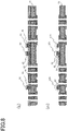
Fig. 12 is a diagram showing a circuit board according to an embodiment. - An embodiment of the present invention will now be described with reference to the drawings.
-
Fig. 1 is a schematic perspective view illustrating the structure of a coil (inductor) of a circuit board according to the embodiment, where (a) shows a glass substrate and through holes as transparent.Fig. 1(b) shows coil wirings as transparent in addition to the glass substrate and through holes. -
Fig. 2 is a schematic cross-sectional view illustrating the structure of a capacitor of the circuit board according to the embodiment. -
Fig. 3 is a circuit diagram illustrating an example of the circuit board according to the embodiment.Fig. 4 is a schematic cross-sectional view of a circuit board according to an embodiment corresponding to the circuit diagram ofFig. 3 . - A
circuit board 100 according to the present embodiment includes aglass substrate 31 having a first surface and a second surface facing away from the first surface; acoil wiring pattern 21 formed on the first surface and acoil wiring pattern 22 formed on the second surface, thecoil wiring patterns coil 110; a throughhole 23 extending through a predetermined portion of theglass substrate 31 from an end of thecoil wiring pattern 21 to an end of thecoil wiring pattern 22; a through hole innerconductive surface 24 formed on the inner side of the throughhole 23, the through hole innerconductive surface 24 enabling electrical connection between the end of thecoil wiring pattern 21 and the end of thecoil wiring pattern 22, thecoil wiring patterns conductive surface 24 constituting thecoil 110 wound around a direction perpendicular to an axis of the throughhole 23 and to a direction in which thecoil wiring patterns electromagnetic shielding layer 39 comprised of conductive material, theelectromagnetic shielding layer 39 disposed directly above thecoil 110. - An example of the
circuit board 100 according to the present embodiment will now be described in detail. Examples of a coil (inductor) and a capacitor formed as circuit elements of an LC circuit will now be described, where a coil (inductor), capacitance, and a substrate comprised of aglass substrate 31 as a core material having wiring layers and insulating resin layers alternately formed on both surfaces thereof are taken as an example. - The formation of the coil (i.e., inductor; represented by the letter L) will now be described. Helical coils can be built into a substrate having through
holes 23.Figs. 1(a) and (b) illustrate aglass substrate 31 as transparent. Theglass substrate 31 has a parallel-plate shape and two rows of through holes.Fig. 1(b) illustrates wiring layers as transparent in addition to theglass substrate 31. InFig. 1(b) ,coil wiring patterns holes 23 are connected to each other; a conductor layer is formed on the inner wall of each throughhole 23 extending from the front surface to the rear surface of theglass substrate 31, resulting in the inner surface of each throughhole 23 being a through hole innerconductive surface 24; thus, through glass vias (TGV) 60 are formed. - The position of the
TGVs 60 is defined as shown inFig. 1(b) . The position of any row of throughholes 23 is defined by X, while the position of throughholes 23 in any row thereof is defined as Y. - Here, a TGV (1, n) 61 is defined as a TGV located in the nth hole position in the first row (i.e., X = 1, Y = n); and a TGV (2, n) 62 is defined as a TGV located in the nth hole position in the second row. The TGV (1, n) 61 and the TGV (2, n) 62 are connected to each other using the
coil wiring pattern 22 on the rear surface, and the TGV (1, n) 61 and the TGV (2, n + 1) 63 are connected to each other using thecoil wiring pattern 21 on the front surface. Thus, thecoil wiring pattern 22, the TGV (1, n) 61, thecoil wiring pattern 21, and the TGV (2, n + 1) 63 form an open circuit such that a conductor extends through the inside and the surface of theglass substrate 31 to produce one turn. When supplied with current, this circuit functions as an inductor. The characteristics of the inductor can be adjusted by changing the number of turns. - The capacitor (represented by the letter C) has a structure in which a dielectric is sandwiched between two conductive plates. As shown in
Fig. 2 , an example of the capacitor is produced as follows: a conductor layer (lower electrode of capacitor) 12 is laminated directly over a glass substrate (not shown) or on an insulating resin layer 11 formed on a glass substrate to form a conductor pattern; and the conductor pattern is further laminated with adielectric layer 13 and a conductor layer (upper electrode of capacitor) 14 in this order. The conductor layer (lower electrode of capacitor) 12 and the conductor layer (upper electrode of capacitor) 14 may each have a multilayer structure comprised of a seed layer and a conductor layer. - A band-pass filter (BPF) using an LC circuit will now be described as an example of a circuit board comprised of a coil (i.e., inductor; represented by the letter L) and a capacitor (represented by the letter C).
Fig. 3 is a basic circuit diagram of a BPF. The electrical capacitance (hereinafter, capacitance) of a capacitor and the induction coefficient (hereinafter, inductance) of an inductor in the circuit can be appropriately set to achieve a bandpass effect of passing frequencies in a desired range and blocking others. -
Fig. 4 is a schematic diagram illustrating an LC circuit formed in thecircuit board 100. The LC circuit is comprised of a coil (i.e., inductor; represented by the letter L) and a capacitor (represented by the letter C) as shown in the circuit diagram ofFig. 3 . InFig. 4 , L1, L2 and L3 each indicate a coil (inductor), while C1, C2 and C3 each indicate a capacitor. - Inductors L1, L2 and L3 can connect TGVs in the
glass substrate 31 and coil wiring patterns on the front and rear surfaces of theglass substrate 31 to form a coil. The inductors L1, L2, and L3 are embedded in theglass substrate 31 and in the insulating resin layers 32 on the front and rear surfaces thereof, and, similarly to the capacitors C1, C2 and C3, conduction with electrodes of the outermost layers of the circuit board can be performed through the via holes in the insulatingresin layer 32. The inductor L2 is a reactive element used in a circuit for suppressing interference between BPFs. - The capacitors C1, C2 and C3 are comprised of a conductor layer (lower electrode of capacitor) 33, a
dielectric layer 34, and a conductor layer (upper electrode of capacitor) 35. Theconductor layer 33, thedielectric layer 34, and theconductor layer 35 are disposed in this order on the upper surface of theglass substrate 31. The capacitors C1, C2 and C3 are embedded as a whole in the insulatingresin layer 32 on the upper surface of theglass substrate 31. These capacitors may be electrically connected to an external electrode of thecircuit board 100 via a conductor inside a via hole formed in the insulatingresin layer 32. - With reference to
Figs. 5 to 12 , an example production process for a circuit board using aglass substrate 31 will now be described. - First, in order to design a circuit, a required capacitance and inductance depending on the frequency bands of the radio waves intended to be passed or blocked are calculated using simulation software. Tables 1 and 2 show the specifications of elements for achieving desired characteristics in the circuit configuration as shown in
Fig. 3 for the band of 3400 MHz or higher and 3600 MHz or lower, for example. For the inductors L1 and L3, having very small inductance, it is not necessary to form a coil shape, and the self-inductance of a single wire is sufficient. For this reason, the dimensions of the wire are shown in the table.[Table 1] C1 C2 C3 Capacitance 5.37 pF 53.59 fF 35.07 pF Dielectric SiN SiN SiN Relative permittivity 6.3 6.3 6.3 Dielectric thickness 200 nm 200 nm 200 nm Side length 138.7 µm 13.9 µm 354.5 µm [Table 2] L1 L2 L3 Inductance 385.4 pH 38.62 nH 59.01 pH Number of turns 11 Coil width 1.6 mm Coil length 1.5 mm Coil thickness 0.3 mm Wire length 1.33 mm 0.2mm Wire width 0.1 mm 0.1 mm Wire thickness 15 µm 15 µm - The capacitance and inductance of the BPFs for 2499 MHz or higher and 2690 MHz or lower are also calculated using the same procedure as that described above to design a required circuit (values are omitted).
- A required circuit board is fabricated on the basis of the circuit design described above. First, a low-expansion glass substrate 31 (
thickness 300 µm, coefficient of thermal expansion: 3.5 ppm/K) is prepared as shown inFig. 5(a) . Then, throughholes 43 having an opening diameter of 80 µm to 100 µm are formed in theglass substrate 31 as shown inFig. 5(b) . In the first step of formation of the throughholes 43, desired positions of theglass substrate 31 are pulse-irradiated with a UV laser beam to form weakened portions in the glass. In the second step, the entire glass plate is etched using a hydrofluoric acid aqueous solution. Thus, the weakened portions are selectively etched, and highly accurate throughholes 43 are quickly formed. In comparison with the case where a glass epoxy substrate is used, throughholes 43 having a more accurate inner diameter and an inner peripheral surface with a reduced unevenness can be formed. - Next, as shown in
Fig. 5(c) , a titanium (Ti) film and a copper (Cu) film are sputter-deposited in this order on the entire surface of theglass substrate 31 as two layers to form acontact layer 44 under the wiring layer and on the inner wall of the throughholes 43 of theglass substrate 31 so that the glass surface has electrical conductivity. The thickness of the Ti film is set to 50 nm, while the thickness of the Cu film is set to 300 nm. - Then, as shown in
Fig. 5(d) , in order to complement thin portions of the contact layer 44 (i.e., the sputter-deposited films) on the inner wall of the throughholes 43, electroless nickel (Ni) plating is applied to form an electrolessNi plating layer 45, resulting in a laminate of the contact layer 44 (i.e., Ti/Cu films)/theNi plating layer 45. This plating is applied to the entire front and rear surfaces of theglass substrate 31 and the inner wall of the throughholes 43, with the plating thickness set to 0.2 µm. Thus, a seed layer is formed. - Although not shown, both surfaces of the
glass substrate 31 are then laminated with, for example, a dry film resist manufactured by Hitachi Chemical Co., Ltd., product name RY-3525 (25 µm thickness) to thereby form aconductor pattern 46 of the inductor wirings, the lower electrode of the capacitor, the pads for external connection and the like by a semi-additive method using the laminate of thecontact layer 44/theNi plating layer 45 as the seed layer. The resist layer may be formed by applying a liquid resist. Then, the resist layer is exposed and developed via a mask for forming a conductor pattern, that is, a wiring pattern, by photolithography to form a wiring pattern (opening) in the resist layer. - Next, copper is deposited in the opening by electrolytic copper plating to form the
conductor pattern 46 as a conductive member with a thickness of 15 µm. In this step, copper plating is also deposited on the inner wall of the throughholes 43 of theglass substrate 31. Subsequently, the dry film resist is removed. In this step, as shown inFig. 6(e) , parts of the front and rear surfaces of theglass substrate 31 are covered with a laminate of the contact layer 44 (i.e., Ti/Cu films)/theNi plating layer 45, and parts of the laminate are copper-plated to form aconductor pattern 46. In the step shown inFig. 6(e) , a lower electrode of the capacitor is formed at a predetermined position on theconductor pattern 46. Alternatively, a lower electrode of the capacitor can also be formed using parts of theconductor pattern 46. - Then, as shown in
Fig. 6(f) , a silicon nitride (SiN) film having a thickness of 200 nm to 400 nm is formed as adielectric layer 34 of the capacitor across a surface of theglass substrate 31 on which the capacitor is to be formed, using a chemical vapor deposition (CVD) method. Further, as shown inFig. 6(g) , a Ti film and a Cu film are formed in this order on the entire surface of thedielectric layer 34 by sputtering at a thickness of 50 nm and 300 nm, respectively, to form aseed layer 48 for formation of the upper electrode of the capacitor. - Subsequently, as shown in
Fig. 7(h) , only portions where the upper electrode of the capacitor is to be formed are exposed through the dry film resistlayer 70 by photolithography. Then, as shown inFig. 7(i) , electrolytic copper plating is applied to form anupper electrode 49 having a thickness of 9 to 10 µm. After that, as shown inFig. 7(j) , the dry film resistlayer 70 is removed. At this time, thedielectric layer 34, SiN layer, and the like are still laminated. - As shown in
Fig. 8(k) , only theupper electrode 49 of the capacitor is first protected by a dry film resistlayer 50 by photolithography in order to remove excess portions of the contact layer, the plating seed layer, and the like. - Then, the substrate is processed by wet etching to remove excess portions of the sputtered copper layer produced during film formation of the
upper electrode 49 of the capacitor, and the substrate is processed by dry etching to remove excess portions of the Ti layer and SiN layer. - More specifically, the uppermost sputtered Cu layer of the excess portions is removed with an etching solution. Then, the sputtered Ti layer and the SiN layer formed by CVD are removed by dry etching. Subsequently, the dry film resist
layer 50 protecting theupper electrode 49 of the capacitor is peeled and removed. As shown inFig. 9(m) , the seed layer directly above theglass substrate 31 is still left. - Then, as shown in
Fig. 9(n) , in order to remove the seed layer of the conductive layer for the lower electrode of the capacitor and the like formed on the surface of theglass substrate 31, the Ni plating layer is processed by wet etching. This processing also removes the sputtered Cu layer thereunder. The Cu layer forming the wiring, capacitor electrode, and the like has a relatively large thickness and is thus not completely removed although dissolved in the etching solution to some extent. Then, the sputtered Ti layer is removed by etching. At this point, theglass substrate 31 is exposed at portions where the wiring, electrode, and the like are not disposed. As a result, acapacitor 120 is formed on the surface of theglass substrate 31, and part of acontinuous wiring 80 which is to form an inductor 110 (seeFig. 10(r) ) is formed, thus connecting to aTGV 60. The contact layer and the seed layer in remaining regions of theglass substrate 31, referred to as glasssubstrate surface regions 90, are removed so that the glasssubstrate surface regions 90 are externally exposed. - Next, as shown in
Fig. 9(o) , an insulating resin, for example, manufactured by Ajinomoto Fine-Techno Co., Inc. (product name "ABF GX-T31R") is attached to both surfaces of theglass substrate 31 to form an insulating resin layer (resin build layer) 32. This processing is performed using a vacuum laminating press machine, and the throughholes 43 of theglass substrate 31 are sealed with an insulating resin without voids. The thickness of the insulatingresin layer 32 is set to approximately 35 µm so that theupper electrode 49 of the capacitor is completely embedded therein. - Further, the insulating
resin layer 32 is processed by laser at a position where electric conduction is desired to thereby form ahole 52 that reaches the wiring layer of theglass substrate 31 as shown inFig. 9(p) . Thehole 52 preferably has a diameter of approximately 60 µm. - Although not shown, the insulating
resin layer 32 on the front and rear surfaces of theglass substrate 31 is processed with an alkaline surface roughening solution to thereby adjust the arithmetic surface roughness Ra to 60 nm. The purpose of this processing is to increase the adhesion of the seed layer in the next step. - Next, as shown in
Fig. 10(q) , electroless Cu plating is applied to the insulatingresin layer 32 on the front and rear surfaces of theglass substrate 31 to form aconductive seed layer 53. Theconductive seed layer 53 preferably has a thickness of 0.6 µm. With this processing, theconductive seed layer 53 is formed not only on the front and rear surfaces of theglass substrate 31 but also on the inner wall of the hole that has been previously formed by laser processing. - Then, as shown in
Fig. 10(r) , a dry film resist layer is attached to both surfaces of the substrate, and an opening is formed by photolithography at positions wherewirings 54 are to be provided. Then, electrolytic plating is applied to the substrate to form wirings having a thickness of 15 µm. Further, in the electrolytic plating, thehole 52 in the insulatingresin layer 32 is filled with copper, and is electrically connected to the conductor layer on the surface of theglass substrate 31. - Then, unnecessary portions of the conductive seed layer are removed by etching. Thus, a
basic circuit board 100 provided with the built-in elements for the LC circuit is completed. In the figure, the built-up wiring on the underside of theglass substrate 31 is shown as if it has a copper layer, which serves as a ground for the capacitor and inductor incorporated in thecircuit board 100. However, this is not necessarily required for an actual circuit board as long as predetermined capacitors and inductors are grounded when the circuit board is completed. - Then, if necessary, the steps of
Fig. 9(o) to Fig. 10(r) are repeated to laminate the insulatingresin layer 92 andconductor wiring layer 91 as shown inFigs. 11(s) and 11(t) , and electronic components are mounted thereon. - As shown in
Fig. 12 , anelectromagnetic shielding layer 39, which is a single-layer electromagnetic shielding layer made of copper, may be disposed directly above the coil (inductor) 110 to suppress mutual interference from passive components. The electromagnetic shielding layer may be formed by sputtering or plating. Disposing the electromagnetic shielding layer on both surfaces of the glass substrate reduces the influence of electromagnetic waves from a motherboard and mounted components. - Flat (e.g., a spiral shape) coils may be formed on the surface of the
glass substrate 31 or the insulatingresin layer 32. - Further, when the
conductor pattern 46 made of copper is laminated on theglass substrate 31, a silicon nitride layer or the like can be provided, for example, directly on theglass substrate 31 in order to prevent occurrence of warpage or cracking of theglass substrate 31 due to stress imbalance. The silicon nitride layer has a function of relieving the residual stress in theconductor pattern 46 of copper. Thus, a built-up wiring layer in which the stress is adjusted can be provided by this combination. However, it should be noted that the silicon nitride layer is merely an example, and is not limited thereto. - Conductive components on one surface of the
glass substrate 31 may be connected to passive components mounted on the circuit board, while conductive components on the other surface of theglass substrate 31 may be connected to a motherboard (not shown). - In the present embodiment, circuit elements are built into a circuit board. This configuration allows other components to be mounted on regions of the circuit board surface located above the circuit elements, thereby providing a compact and high-performance circuit board. When mounted with switching components, the circuit board according to the present embodiment was observed to operate with stability and less noise.
-
- 11 ... Insulating resin layer
- 12 ... Conductor layer (lower electrode of capacitor)
- 13 ... Dielectric layer
- 14 ... Conductor layer (upper electrode of capacitor)
- 21, 22 ... Coil wiring pattern
- 23 ... Through hole
- 24 ... Through hole inner conductive surface
- 31 ... Glass substrate
- 32 ... Insulating resin layer
- 33 ... Conductor layer (lower electrode of capacitor)
- 34 ... Dielectric layer
- 35 ... Conductor layer (upper electrode of capacitor)
- 36 ... Passive component
- 37 ... Active component
- 38 ... Mold resin
- 39 ... Electromagnetic shielding layer
- 43 ... Through hole
- 44 ... Contact layer (sputtered layer of titanium (Ti)/sputtered layer of copper (Cu))
- 45 ... Layer of nickel (Ni) plating
- 46 ... Conductor pattern (copper wiring directly above glass: including lower electrode of capacitor)
- 48 ... Seed layer (sputtered layer of titanium (Ti)/sputtered layer of copper (Cu); above dielectric layer)
- 49 ... Upper electrode of capacitor
- 50 ... Dry film resist layer (for capacitor protection)
- 52 ... Hole in insulating resin layer
- 53 ... Conductive seed layer
- 54 ... Wiring
- 60 ... Through glass via (TGV)
- 61 ... TGV (1, n)
- 62 ... TGV (2, n)
- 63 ... TGV (2, n + 1)
- 70 ... Dry film resist layer
- 80 ... Wiring
- 90 ... Glass substrate surface region
- 91 ... Conductor wiring layer
- 92 ... Insulating resin layer
- 100 ... Circuit board
- 110 ... Coil (inductor)
- 120 ... Capacitor
- C1, C2, C3 ... Capacitor
- X ... Row position
- Y ... Hole position in row
- n ... Position of any hole in row
Claims (6)
- A circuit board comprising:a glass substrate having a first surface and a second surface facing away from the first surface;a first coil wiring pattern formed on the first surface and a second coil wiring pattern formed on the second surface, the first and second coil wiring patterns each constituting part of at least one coil;a through hole extending through a predetermined portion of the glass substrate from an end of the first coil wiring pattern to an end of the second coil wiring pattern;a through hole inner conductive surface formed on an inner side of the through hole, the through hole inner conductive surface enabling electrical connection between the end of the first coil wiring pattern and the end of the second coil wiring pattern,the first and second coil wiring patterns and the through hole inner conductive surface constituting the at least one coil wound around a direction perpendicular to an axis of the through hole and to a direction in which the first and second coil wiring patterns extend; andan electromagnetic shielding layer comprised of conductive material, the electromagnetic shielding layer shielding against electromagnetic waves generated by the at least one coil.
- The circuit board according to claim 1, characterized in that the electromagnetic shielding layer is disposed directly above the at least one coil.
- The circuit board according to claim 1, characterized in that the electromagnetic shielding layer is disposed to entirely cover the at least one coil.
- The circuit board according to claim 1, characterized in that the electromagnetic shielding layer is comprised of an insulating resin layer and a conductor layer, an area of the conductor layer being greater than or equal to that of a coil pattern.
- The circuit board according to claim 4, characterized in that the electromagnetic shielding layer comprises a plurality of electromagnetic shielding layers each including at least one layer which is the insulating resin layer, the electromagnetic shielding layers being arranged such that one of the electromagnetic shielding layers may constitute an outermost layer of the circuit board.
- The circuit board according to claim 4 or 5, characterized in that the conductor layer of the electromagnetic shielding layer includes non-magnetic metal.
Applications Claiming Priority (2)
| Application Number | Priority Date | Filing Date | Title |
|---|---|---|---|
| JP2018227135 | 2018-12-04 | ||
| PCT/JP2019/046015 WO2020116228A1 (en) | 2018-12-04 | 2019-11-25 | Circuit board |
Publications (2)
| Publication Number | Publication Date |
|---|---|
| EP3893610A1 true EP3893610A1 (en) | 2021-10-13 |
| EP3893610A4 EP3893610A4 (en) | 2022-02-09 |
Family
ID=70975390
Family Applications (1)
| Application Number | Title | Priority Date | Filing Date |
|---|---|---|---|
| EP19891733.8A Pending EP3893610A4 (en) | 2018-12-04 | 2019-11-25 | Circuit board |
Country Status (5)
| Country | Link |
|---|---|
| US (1) | US20210298172A1 (en) |
| EP (1) | EP3893610A4 (en) |
| JP (1) | JPWO2020116228A1 (en) |
| CN (1) | CN112997589A (en) |
| WO (1) | WO2020116228A1 (en) |
Families Citing this family (4)
| Publication number | Priority date | Publication date | Assignee | Title |
|---|---|---|---|---|
| JP2022054538A (en) * | 2020-09-28 | 2022-04-07 | 凸版印刷株式会社 | Wiring board |
| WO2022203037A1 (en) * | 2021-03-26 | 2022-09-29 | 凸版印刷株式会社 | Wiring board manufacturing method and wiring board |
| WO2022222131A1 (en) * | 2021-04-23 | 2022-10-27 | 京东方科技集团股份有限公司 | Substrate integrated with passive device, and preparation method therefor |
| CN116209134A (en) | 2021-11-30 | 2023-06-02 | 鹏鼎控股(深圳)股份有限公司 | Circuit board assembly and manufacturing method thereof |
Family Cites Families (12)
| Publication number | Priority date | Publication date | Assignee | Title |
|---|---|---|---|---|
| US5461353A (en) * | 1994-08-30 | 1995-10-24 | Motorola, Inc. | Printed circuit board inductor |
| US6531945B1 (en) * | 2000-03-10 | 2003-03-11 | Micron Technology, Inc. | Integrated circuit inductor with a magnetic core |
| CN101040354B (en) * | 2004-10-18 | 2011-07-20 | 株式会社村田制作所 | Method for manufacturing monolithic ceramic electronic component, and multilayer composite |
| KR100750738B1 (en) * | 2005-06-27 | 2007-08-22 | 삼성전자주식회사 | Inductor and method for manufacturing thereof, micro device package and method for manufacturing cap of the micro device package |
| US20130207745A1 (en) * | 2012-02-13 | 2013-08-15 | Qualcomm Incorporated | 3d rf l-c filters using through glass vias |
| CN102800647A (en) * | 2012-08-22 | 2012-11-28 | 上海宏力半导体制造有限公司 | Three-dimensional spiral inductor and forming method thereof |
| US20140104284A1 (en) * | 2012-10-16 | 2014-04-17 | Qualcomm Mems Technologies, Inc. | Through substrate via inductors |
| US10070533B2 (en) * | 2015-09-30 | 2018-09-04 | 3D Glass Solutions, Inc. | Photo-definable glass with integrated electronics and ground plane |
| US10755190B2 (en) * | 2015-12-21 | 2020-08-25 | D-Wave Systems Inc. | Method of fabricating an electrical filter for use with superconducting-based computing systems |
| JP2018078133A (en) * | 2016-11-07 | 2018-05-17 | 凸版印刷株式会社 | Built-in coil glass substrate and build-up substrate |
| JP2018160607A (en) * | 2017-03-23 | 2018-10-11 | 大日本印刷株式会社 | Through-electrode substrate, mounting board with through-electrode substrate, and method for manufacturing through-electrode substrate |
| JP7068638B2 (en) * | 2017-05-19 | 2022-05-17 | 大日本印刷株式会社 | Wiring board and mounting board |
-
2019
- 2019-11-25 CN CN201980073968.8A patent/CN112997589A/en active Pending
- 2019-11-25 WO PCT/JP2019/046015 patent/WO2020116228A1/en unknown
- 2019-11-25 EP EP19891733.8A patent/EP3893610A4/en active Pending
- 2019-11-25 JP JP2020559067A patent/JPWO2020116228A1/en active Pending
-
2021
- 2021-06-03 US US17/338,524 patent/US20210298172A1/en active Pending
Also Published As
| Publication number | Publication date |
|---|---|
| JPWO2020116228A1 (en) | 2021-09-02 |
| US20210298172A1 (en) | 2021-09-23 |
| EP3893610A4 (en) | 2022-02-09 |
| CN112997589A (en) | 2021-06-18 |
| WO2020116228A1 (en) | 2020-06-11 |
Similar Documents
| Publication | Publication Date | Title |
|---|---|---|
| US20210298172A1 (en) | Circuit board | |
| KR101079347B1 (en) | Integrated passive devices fabricated utilizing multi-layer organic laminates | |
| EP3550942A1 (en) | Electronic component and method for manufacturing electronic component | |
| WO2003050909A1 (en) | Circuit board device and its manufacturing method | |
| EP4089724A1 (en) | Circuit board | |
| US11303261B2 (en) | Circuit board | |
| EP4064803A1 (en) | Glass-core multilayer wiring substrate and method for manufacturing same | |
| US10930435B2 (en) | Multilayer element and LC filter | |
| US20230039184A1 (en) | Glass core wiring substrate incorporating high-frequency filter, high-frequency module using the same, and method of manufacturing glass core wiring substrate incorporating high-frequency filter | |
| US12101074B2 (en) | Multilayer circuit board with LC resonant circuit and electronic component package including multilayer circuit board with LC resonant circuit | |
| JP4693588B2 (en) | Bandpass filter | |
| JP2007019292A (en) | Electronic component module and laminated substrate for it | |
| JP7383215B2 (en) | circuit board | |
| KR100660652B1 (en) | Mmic electromagnetic noise filter and microwave integrated circuit device incluing the same | |
| EP4221471A1 (en) | Wiring board | |
| EP4163941A1 (en) | Multilayer wiring board and module comprising multilayer wiring board | |
| JP2780166B2 (en) | Stripline filter bandwidth adjustment method | |
| JPH1051257A (en) | Lc low-pass filter | |
| JP2021007127A (en) | Glass-core multi-layer circuit board | |
| JP2021114582A (en) | Circuit board for mounting electronic component | |
| JP2020113674A (en) | Electronic substrate for high frequency module | |
| WO1998033229A1 (en) | Dielectric resonator, dielectric filter, dielectric duplexer, and method for manufacturing dielectric resonator |
Legal Events
| Date | Code | Title | Description |
|---|---|---|---|
| STAA | Information on the status of an ep patent application or granted ep patent |
Free format text: STATUS: THE INTERNATIONAL PUBLICATION HAS BEEN MADE |
|
| PUAI | Public reference made under article 153(3) epc to a published international application that has entered the european phase |
Free format text: ORIGINAL CODE: 0009012 |
|
| STAA | Information on the status of an ep patent application or granted ep patent |
Free format text: STATUS: REQUEST FOR EXAMINATION WAS MADE |
|
| 17P | Request for examination filed |
Effective date: 20210703 |
|
| AK | Designated contracting states |
Kind code of ref document: A1 Designated state(s): AL AT BE BG CH CY CZ DE DK EE ES FI FR GB GR HR HU IE IS IT LI LT LU LV MC MK MT NL NO PL PT RO RS SE SI SK SM TR |
|
| A4 | Supplementary search report drawn up and despatched |
Effective date: 20220111 |
|
| RIC1 | Information provided on ipc code assigned before grant |
Ipc: H01G 4/30 20060101ALI20220104BHEP Ipc: H01F 27/00 20060101ALI20220104BHEP Ipc: H05K 3/46 20060101ALI20220104BHEP Ipc: H03H 7/01 20060101ALI20220104BHEP Ipc: H01L 23/12 20060101ALI20220104BHEP Ipc: H01F 27/36 20060101ALI20220104BHEP Ipc: H01F 17/00 20060101ALI20220104BHEP Ipc: H05K 1/16 20060101AFI20220104BHEP |
|
| DAV | Request for validation of the european patent (deleted) | ||
| DAX | Request for extension of the european patent (deleted) |