EP3893414A1 - Wireless communication system, accommodation station device, and wireless communication method - Google Patents
Wireless communication system, accommodation station device, and wireless communication method Download PDFInfo
- Publication number
- EP3893414A1 EP3893414A1 EP20744618.8A EP20744618A EP3893414A1 EP 3893414 A1 EP3893414 A1 EP 3893414A1 EP 20744618 A EP20744618 A EP 20744618A EP 3893414 A1 EP3893414 A1 EP 3893414A1
- Authority
- EP
- European Patent Office
- Prior art keywords
- signals
- optically modulated
- wavelengths
- transmission
- optical
- Prior art date
- Legal status (The legal status is an assumption and is not a legal conclusion. Google has not performed a legal analysis and makes no representation as to the accuracy of the status listed.)
- Granted
Links
Images












Classifications
-
- H—ELECTRICITY
- H01—ELECTRIC ELEMENTS
- H01Q—ANTENNAS, i.e. RADIO AERIALS
- H01Q1/00—Details of, or arrangements associated with, antennas
- H01Q1/12—Supports; Mounting means
- H01Q1/22—Supports; Mounting means by structural association with other equipment or articles
- H01Q1/24—Supports; Mounting means by structural association with other equipment or articles with receiving set
- H01Q1/241—Supports; Mounting means by structural association with other equipment or articles with receiving set used in mobile communications, e.g. GSM
- H01Q1/246—Supports; Mounting means by structural association with other equipment or articles with receiving set used in mobile communications, e.g. GSM specially adapted for base stations
-
- H—ELECTRICITY
- H04—ELECTRIC COMMUNICATION TECHNIQUE
- H04B—TRANSMISSION
- H04B10/00—Transmission systems employing electromagnetic waves other than radio-waves, e.g. infrared, visible or ultraviolet light, or employing corpuscular radiation, e.g. quantum communication
- H04B10/50—Transmitters
- H04B10/516—Details of coding or modulation
- H04B10/548—Phase or frequency modulation
-
- H—ELECTRICITY
- H01—ELECTRIC ELEMENTS
- H01Q—ANTENNAS, i.e. RADIO AERIALS
- H01Q21/00—Antenna arrays or systems
- H01Q21/06—Arrays of individually energised antenna units similarly polarised and spaced apart
- H01Q21/08—Arrays of individually energised antenna units similarly polarised and spaced apart the units being spaced along or adjacent to a rectilinear path
-
- H—ELECTRICITY
- H01—ELECTRIC ELEMENTS
- H01Q—ANTENNAS, i.e. RADIO AERIALS
- H01Q3/00—Arrangements for changing or varying the orientation or the shape of the directional pattern of the waves radiated from an antenna or antenna system
- H01Q3/26—Arrangements for changing or varying the orientation or the shape of the directional pattern of the waves radiated from an antenna or antenna system varying the relative phase or relative amplitude of energisation between two or more active radiating elements; varying the distribution of energy across a radiating aperture
- H01Q3/2676—Optically controlled phased array
-
- H—ELECTRICITY
- H04—ELECTRIC COMMUNICATION TECHNIQUE
- H04B—TRANSMISSION
- H04B10/00—Transmission systems employing electromagnetic waves other than radio-waves, e.g. infrared, visible or ultraviolet light, or employing corpuscular radiation, e.g. quantum communication
- H04B10/11—Arrangements specific to free-space transmission, i.e. transmission through air or vacuum
-
- H—ELECTRICITY
- H04—ELECTRIC COMMUNICATION TECHNIQUE
- H04B—TRANSMISSION
- H04B10/00—Transmission systems employing electromagnetic waves other than radio-waves, e.g. infrared, visible or ultraviolet light, or employing corpuscular radiation, e.g. quantum communication
- H04B10/25—Arrangements specific to fibre transmission
- H04B10/2575—Radio-over-fibre, e.g. radio frequency signal modulated onto an optical carrier
- H04B10/25752—Optical arrangements for wireless networks
-
- H—ELECTRICITY
- H04—ELECTRIC COMMUNICATION TECHNIQUE
- H04J—MULTIPLEX COMMUNICATION
- H04J14/00—Optical multiplex systems
- H04J14/02—Wavelength-division multiplex systems
- H04J14/03—WDM arrangements
- H04J14/0305—WDM arrangements in end terminals
Definitions
- the present invention relates to a wireless communication system, an accommodation station apparatus, and a wireless communication method.
- millimeter wave bands are attracting attention as frequency bands capable of high-speed transmission.
- long-distance transmission is difficult with millimeter wave bands because their propagation loss is great.
- a radio over fiber (RoF) system is known as a solution to this problem.
- an accommodation station (a master station) modulates the intensity of an optical carrier with a radio frequency (RF) signal to be transmitted and transmits the modulated signal through an optical fiber.
- RF radio frequency
- a base station (a slave station) reconverts the optical signal received through the optical fiber to the RF signal and radiates the reconverted RF signal through an antenna as a radio wave.
- Use of such an RoF system enables long-distance transmission of RF signals of millimeter wave bands.
- One solution is beamforming using an array antenna.
- the phases of RF signals incident on antenna elements of the array antenna are controlled such that radio waves radiated from the antenna elements interfere with each other. This controls an overall radiation direction of radio waves.
- the phases of RF signals incident on antenna elements are controlled by controlling the wavelengths of optical carriers utilizing the fact that delay differences occur between optical signals of wavelengths due to chromatic dispersion during transmission through an optical fiber (see, for example, Patent Document 1).
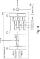
- Fig. 20 is a block diagram of an RoF system 900 to which the technique of Patent Document 1 is applied.
- a multi-wavelength variable light source 911 in an accommodation station 910 outputs a plurality of optical signals.
- the wavelength intervals between the optical signals can be changed arbitrarily.
- An optical modulator 912 modulates an optical signal of each wavelength with an RF signal to be transmitted.
- the optical modulator 912 outputs a plurality of optically modulated signals.
- Each optically modulated signal is transmitted though the optical fiber 920.
- the optically modulated signals undergo different delay differences depending on the wavelengths due to the influence of chromatic dispersion.
- An optical demultiplexer 931 in a base station 930 splits a plurality of optically modulated signals transmitted through the optical fiber 920 into respective optically modulated signals of the wavelengths.
- a plurality of optical to electrical (O/E) converters 932-1, ..., 932-n convert the split optically modulated signals of the wavelengths into electrical signals.
- Antenna elements 933-1, ..., 933-n radiate the converted electrical signals as RF signals. At this time, phase differences also occur between the RF signals because of the delay differences due to chromatic dispersion during transmission through the optical fiber 920, so that directivity can be formed.
- wavelengths are not controlled but fixed wavelengths are assigned to antenna elements and chromatic dispersion or path differences are used to cause delay differences between optical signals of the wavelengths (see, for example, Non Patent Document 1).
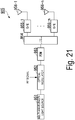
- Fig. 21 is a diagram of a wireless system 905 to which the technique of Non Patent Document 1 is applied.
- a multi-wavelength light source 951 outputs a plurality of optical signals of different wavelengths.
- An optical modulator 952 modulates an optical signal of each wavelength with an RF signal to be transmitted. Thus, the optical modulator 952 outputs a plurality of optically modulated signals.
- Each optically modulated signal is sent to a programmable dispersion matrix (PDM) 953.
- PDM programmable dispersion matrix
- Fig. 22 is a block diagram illustrating the configuration of the PDM 953.
- the PDM 953 includes n + 1 pieces of 2 ⁇ 2 optical switches 961-1, ..., 961-(n + 1) and n dispersion elements 962-1, 962-2, ..., 962-n which have dispersion values of D 0 , 2D 0 , ..., 2 n-1 D 0 , respectively.
- the dispersion elements 962-1, ..., 962-n are each made of a dispersion fiber, a grating fiber, or the like.
- the PDM 953 adjusts the dispersion values as a whole by switching the 2 ⁇ 2 optical switches 961-1, ..., 961-(n + 1).
- the optically modulated signals input to the PDM 953 undergo different delay differences depending on the dispersion values adjusted by the PDM 953.
- An optical demultiplexer 954 in the wireless system 905 illustrated in Fig. 21 splits a plurality of optically modulated signals output from the PDM 953 into respective optically modulated signals of the wavelengths. This optical splitting is fixed because the wavelengths are preset corresponding to antenna elements 956-1, ..., 956-n.
- a plurality of optical to electrical (O/E) converters 955-1, ..., 955-n convert the split optically modulated signal of the wavelengths into electrical signals.
- the antenna elements 956-1, ..., 956-n radiate the converted electrical signals as RF signals. At this time, phase differences also occur between the RF signals because of the delay differences due to the dispersion of the PDM 953, so that directivity can be formed.
- Patent Document 1 JP 4246724 B
- Non Patent Document 1 Dennis TK Tong, Ming C. Wu, "A Novel Multiwavelength Optically Controlled Phased Array Antenna with a Programmable Dispersion Matrix", IEEE Photonics Technology Letters, June 1996, VOL. 8, NO. 6, pp. 812-814
- Patent Document 1 makes wavelengths variable and dispersion fixed to cause delay differences between modulated optical signals as described above.
- This increases the width of a wavelength band to be used and thus the wavelength utilization efficiency seems to be lowered.
- Different wavelengths must be used for base stations particularly in a wavelength division multiplex-passive optical network (WDM-PON). If the technique of Patent Document 1 is applied to such a situation, a wavelength band for beamforming must also be preset in the WDM-PON, greatly expanding the wavelength band to be used.
- WDM-PON wavelength division multiplex-passive optical network
- the wavelengths are adjusted for directivity formation.
- the optical demultiplexer of the base station needs to change the wavelengths sent to the antenna elements of the base station every time the directivity is formed, and when the directivity is changed dynamically, splitting of the optical demultiplexer also needs to be changed dynamically. This means that it is necessary to control the optical demultiplexer of the base station.
- the base station can be simplified by consolidating the functions into the accommodation station, in addition to the long-distance transmission of RF signals.
- the technique of Patent Document 1 requires control of the optical demultiplexer of the base station, limiting the simplification of the base station.
- Patent Document 1 requires distance information of the optical fiber in the wavelength adjustment for adjusting the delay differences between optically modulated signals.
- the distance information of the optical fiber from the accommodation station to the base station is considered to be unknown, or even if known, the exact length cannot be known. It is very difficult to measure the fiber length particularly when the optical fiber is in a passive optical network (PON) configuration.
- PON passive optical network
- the applicable range of Patent Document 1 seems to be very limited because it requires accurate distance information of an optical fiber.
- Non Patent Document 1 makes the wavelengths fixed and the dispersion variable to cause delay differences between modulated optical signals.
- the wavelength utilization efficiency is better than that of Patent Document 1 because the wavelengths are fixed. It is also unnecessary to control the optical demultiplexer because the optical splitting is fixed.
- high accuracy seems to be required for the design and manufacture of the PDM for adjusting the dispersion. Thus, there is a risk of increasing the size and cost of apparatuses.
- Non Patent Document 1 does not mention application to RoF. Therefore, when RoF is applied to Non Patent Document 1 for long-distance optical fiber transmission, the influence of chromatic dispersion during transmission through the optical fiber must be taken into consideration, in addition to the dispersion adjustment by the PDM. Further, both Patent Document 1 and Non Patent Document 1 mention only beamforming of transmitting antennas and do not mention beamforming of receiving antennas.
- An aspect of the present invention provides a wireless communication system including an accommodation station apparatus; a base station apparatus that is connected to the accommodation station apparatus through an optical transmission line and has n antenna elements where n is an integer of 2 or more; and a terminal configured to wirelessly communicate with the base station apparatus.
- the accommodation station apparatus includes: a transmission unit configured to adjust phases of optically modulated transmission signals, obtained respectively by modulating light of n different first wavelengths with a transmission signal, by first amounts of phase adjustment corresponding respectively to the n different first wavelengths and output a combined optically modulated transmission signal obtained by combining the phase-adjusted optically modulated transmission signals of the n different first wavelengths to the optical transmission line; a transmission phase control unit configured to, when transmitting p beacon signals where p is an integer of 2 or more as the transmission signal, control the transmission unit such that the transmission unit adjusts phases of the p beacons signals by the first amounts of phase adjustment which differ between the p beacon signals; a reception unit configured to demultiplex a combined optically modulated received signal transmitted through the optical transmission line into optically modulated received signals of n different second wavelengths and convert the demultiplexed optically modulated received signals into electrical signals which have been phase-adjusted by second amounts of phase adjustment corresponding respectively to the n different second wavelengths; a reception phase
- the base station apparatus includes: a base station optical demultiplexing unit configured to demultiplex the combined optically modulated transmission signal transmitted through the optical transmission line into optically modulated transmission signals of the n different first wavelengths; an optical to electrical conversion unit configured to convert the optically modulated transmission signals of the n first wavelengths into electrical signals and radiate the electrical signals wirelessly from the antenna elements corresponding respectively to the n first wavelengths; an electrical to optical conversion unit configured to modulate optical signals of the n different second wavelengths corresponding respectively to the n antenna elements with wireless signals that the n antenna elements have received from the terminal to generate optically modulated received signals; and a base station optical combining unit configured to output a combined optically modulated received signal obtained by combining the optically modulated received signals of the n second wavelengths generated by the electrical to optical conversion unit to the optical transmission line.
- the terminal includes: a wireless reception unit configured to receive a wireless signal from the base station apparatus; a wireless transmission unit configured to transmit a wireless signal to the base station apparatus; and a beacon selection unit configured to, when the wireless reception unit has received the p beacon signals, cause the wireless transmission unit to transmit q wireless signals indicating the identification information of the beacon signal selected based on the received powers of the p beacon signals.
- An aspect of the present invention provides the above wireless communication system, wherein the n antenna elements are arranged at predetermined intervals, the n first wavelengths are wavelengths at first wavelength intervals included in a range in which chromatic dispersion in the optical transmission line is capable of being regarded as constant, the n second wavelengths are wavelengths at second wavelength intervals included in a range in which chromatic dispersion in the optical transmission line is capable of being regarded as constant, the n first amounts of phase adjustment are amounts of phase adjustment which make phases of wireless signals spaced at first phase intervals, and the n second amounts of phase adjustment are amounts of phase adjustment which make phases of wireless signals spaced at second phase intervals.
- the transmission unit includes: an optical modulation unit configured to modulate light of the n different first wavelengths with the transmission signal to generate optically modulated transmission signals; a phase adjustment unit configured to adjust phases of the optically modulated transmission signals of the n first wavelengths generated by the optical modulation unit by the first amounts of phase adjustment corresponding respectively to the first wavelengths; and an optical combining unit configured to combine the optically modulated transmission signals of the n first wavelengths which have been phase-adjusted by the phase adjustment unit to generate a combined optically modulated transmission signal and output the combined optically modulated transmission signal to the optical transmission line.
- the transmission unit includes: a splitting unit configured to split the transmission signal into n transmission signals corresponding respectively to the n different first wavelengths; a phase adjustment unit configured to adjust phases of the n transmission signals split by the splitting unit by the first amounts of phase adjustment corresponding to the first wavelengths corresponding to the n transmission signals; an optical modulation unit configured to modulate light of the n different first wavelengths with the transmission signals which have been phase-adjusted by the first amounts of phase adjustment corresponding to the first wavelengths to generate optically modulated transmission signals; and an optical combining unit configured to combine the optically modulated transmission signals of the n first wavelengths generated by the optical modulation unit to generate a combined optically modulated transmission signal and output the combined optically modulated transmission signal to the optical transmission line.
- the reception unit includes: a demultiplexing unit configured to demultiplex the combined optically modulated received signal into optically modulated received signals of the n second wavelengths; a phase adjustment unit configured to adjust phases of the optically modulated received signals of the n second wavelengths demultiplexed by the demultiplexing unit by the second amounts of phase adjustment corresponding to the second wavelengths; a combining unit configured to combine the optically modulated received signals of the n second wavelengths which have been phase-adjusted by the phase adjustment unit; and a conversion unit configured to convert the optically modulated received signals combined by the combining unit into electrical signals.
- the reception unit includes: a demultiplexing unit configured to demultiplex the combined optically modulated received signal into optically modulated received signals of the n second wavelengths; a conversion unit configured to convert the optically modulated received signals of the n second wavelengths demultiplexed by the demultiplexing unit into electrical signals; and a phase adjustment unit configured to adjust phases of the n electrical signals obtained through conversion of the conversion unit by the second amounts of phase adjustment corresponding to the second wavelengths.
- An aspect of the present invention provides an accommodation station apparatus connected to a base station apparatus through an optical transmission line, the base station apparatus being configured to perform wireless communication with a terminal through n antenna elements where n is an integer of 2 or more, the accommodation station apparatus including: a transmission unit configured to adjust phases of optically modulated transmission signals, obtained respectively by modulating light of n different first wavelengths corresponding to the n antenna elements with a transmission signal, by first amounts of phase adjustment corresponding respectively to the n first wavelengths and output a combined optically modulated transmission signal obtained by combining the phase-adjusted optically modulated transmission signals of the n first wavelengths to the optical transmission line; a transmission phase control unit configured to, when transmitting p beacon signals where p is an integer of 2 or more as the transmission signals, control the transmission unit such that the transmission unit adjusts phases of the p beacons signals by the first amounts of phase adjustment which differ between the p beacon signals; a reception unit configured to demultiplex a combined optically modulated received signal transmitted through the optical transmission line into optically
- An aspect of the present invention provides a wireless communication method for a wireless communication system including an accommodation station apparatus, a base station apparatus that is connected to the accommodation station apparatus through an optical transmission line and has n antenna elements where n is an integer of 2 or more, and a terminal configured to wirelessly communicate with the base station apparatus, the wireless communication method including: a transmission step in which the accommodation station apparatus adjusts phases of optically modulated transmission signals, obtained respectively by modulating light of n different first wavelengths with a transmission signal, by first amounts of phase adjustment corresponding respectively to the n different first wavelengths, and outputs a combined optically modulated transmission signal obtained by combining the phase-adjusted optically modulated transmission signals of the n different first wavelengths to the optical transmission line; a transmission phase control step in which the accommodation station apparatus, when transmitting p beacon signals where p is an integer of 2 or more as the transmission signals in the transmission step, performs control to adjust phases of the p beacons signals by the first amounts of phase adjustment which differ between the p beacon signals; a reception step
- the present invention it is possible to perform beamforming of transmitting and receiving antennas of an RoF system while limiting deterioration of wavelength utilization efficiency and cost increase without requiring base station control and optical fiber distance information.
- Fig. 1 is a diagram illustrating an overall configuration of a wireless communication system 10 according to an embodiment of the present invention.
- the wireless communication system 10 includes an accommodation station 20, a base station 40, and a terminal 50.
- the accommodation station 20 and the base station 40 are connected by an optical fiber 30.
- the accommodation station 20 and the base station 40 perform optical fiber communication, and the base station 40 and the terminal 50 perform wireless communication.
- the accommodation station 20, the optical fiber 30, and the base station 40 constitute, for example, an RoF system.
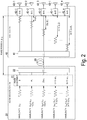
- Fig. 2 is a diagram illustrating the basic principle of beamforming of transmitting antennas according to the present embodiment.
- Fig. 2 illustrates only functional units relating to transmission.
- the accommodation station 20 includes a phase adjustment unit 21 and an optical combiner 22.
- the base station 40 includes an optical demultiplexer 41, n optical to electrical (O/E) converters 42 (where n is an integer of 2 or more), and n antenna elements 43.
- the n antenna elements 43-1, ..., 43-n of the base station 40 are fixedly associated with different wavelengths ⁇ 11 , ..., ⁇ 1n , respectively. This can eliminate the need to control the optical demultiplexer of the base station as in Patent Document 1.
- the dispersion values for the wavelengths ⁇ 11 , ..., ⁇ 1n can be considered to be equal because the wavelength interval is sufficiently small. Further, delay differences between optical signals of wavelengths ⁇ 11 , ..., ⁇ 1n due to chromatic dispersion when the optical signals are transmitted through the optical fiber by the same distance can be made equal because the wavelengths are at equal intervals.
- the optical combiner 22 of the accommodation station 20 wavelength-multiplexes the optically modulated signals of wavelengths ⁇ 11 , ..., ⁇ 1n which have been phase-adjusted by the phase adjustment unit 21 and transmits the multiplexed optically modulated signal up to the base station 40 through the single optical fiber 30. At this time, it is unnecessary to know distance information of the optical fiber 30.
- optically modulated signals of wavelengths ⁇ 11 , ..., ⁇ 1n When optically modulated signals of wavelengths ⁇ 11 , ..., ⁇ 1n are transmitted through an optical fiber, they undergo different delay differences under the influence of chromatic dispersion and thus experience different phase rotations. Because the wavelengths ⁇ 11 , ..., ⁇ 1n are arranged at equal intervals which are sufficiently small wavelength intervals, the delay differences due to chromatic dispersion can also be made at equal intervals. The amounts of phase rotation of the RF signals of the optically modulated signals of wavelengths ⁇ 11 , ..., ⁇ 1n are also at equal intervals.
- the amounts of phase rotation ⁇ 11 , ..., ⁇ 1n of the RF signals of the optically modulated signals of wavelengths ⁇ 11 , ..., ⁇ 1n are ⁇ 11 , ⁇ 11 - ⁇ 1 , ⁇ 11 - 2 ⁇ 1 , ..., ⁇ 11 - (n - 1) ⁇ 1 , respectively.
- the amounts of phase rotation ⁇ 11 , ..., ⁇ 1n of the RF signals are constants because the wavelengths ⁇ 11 , ..., ⁇ 1n are fixed. However, the values of the amounts of phase rotation ⁇ 11 , ..., ⁇ 1n of the RF signals cannot be specifically obtained if the distance information of the optical fiber 30 is unknown.
- the optically modulated signals of wavelengths ⁇ 11 , ..., ⁇ 1n are O/E converted respectively by the O/E converters 42-1, ..., 42-n and the RF signals thereof are radiated from the antenna elements 43-1, ..., 43-n, respectively.
- Fig. 3 is a diagram illustrating the beam direction of transmitted RF signals radiated from the base station 40.
- the antenna elements 43-1, ..., 43-n are assumed to be arranged at equal intervals d. That is, the interval between the antenna element 43-i and the antenna element 43-(i + 1) is d.
- ⁇ 1 is a constant whose specific value is unknown.
- a variable that determines the transmission beam direction ⁇ is only ⁇ 1 and the transmission beam direction ⁇ can be changed by changing the value of ⁇ 1 .
- the base station 40 in controlling the transmission beam direction because the accommodation station 20 controls the value of ⁇ 1 .
- the distance information of the optical fiber 30 is unknown, a specific value of ⁇ 1 is unknown and therefore a specific value of the transmission beam direction ⁇ is also unknown.
- the direction of the transmission beam formed by the base station 40 is unknown.
- feedback from the terminal 50, which is a communication partner of the base station 40 is required to determine the transmission beam direction.
- a beam direction determination process will be described in detail after beamforming of the receiving antennas is described.
- Fig. 4 is a diagram illustrating the basic principle of beamforming of receiving antennas in the wireless communication system 10 according to the present embodiment.
- Fig. 4 illustrates only functional units relating to reception.
- the accommodation station 20 includes an optical demultiplexer 23 and a phase adjustment unit 24.
- the base station 40 includes n antenna elements 43-1, ..., 43-n, n electrical to optical (E/O) converters 44, and an optical combiner 45.
- the n antenna elements 43-1, ..., 43-n of the base station 40 are fixedly associated with different wavelengths ⁇ 21 , ..., ⁇ 2n , respectively.
- the dispersion values for the wavelengths ⁇ 21 , ..., ⁇ 2n can be regarded equal because the wavelength interval is sufficiently small. Further, delay differences between optical signals of wavelengths ⁇ 21 , ..., ⁇ 2n due to chromatic dispersion when the optical signals are transmitted through the optical fiber by the same distance can be made equal because the wavelengths are at equal intervals.
- a signal from the terminal 50 is assumed to arrive at the base station 40 in the direction ⁇ as illustrated in Fig. 3 .
- optically modulated signals of wavelengths ⁇ 21 , ..., ⁇ 2n When optically modulated signals of wavelengths ⁇ 21 , ..., ⁇ 2n are transmitted through an optical fiber, they undergo different delay differences under the influence of chromatic dispersion and thus experience different phase rotations. Because the wavelengths ⁇ 21 , ..., ⁇ 2n are arranged at equal intervals which are sufficiently small wavelength intervals, the delay differences due to chromatic dispersion are at equal intervals and the amounts of phase rotation of the RF signals of the optically modulated signals of wavelengths ⁇ 21 , ..., ⁇ 2n are also at equal intervals.
- the amounts of phase rotation ⁇ 21 , ..., ⁇ 2n of the RF signals of the optically modulated signals of wavelengths ⁇ 21 , ..., ⁇ 2n are ⁇ 21 , ⁇ 21 - ⁇ 2 , ⁇ 21 - 2 ⁇ 2 , ..., ⁇ 21 - (n - 1) ⁇ 2 , respectively.
- the amounts of phase rotation ⁇ 21 , ..., ⁇ 2n of the RF signals are constants because the wavelengths ⁇ 21 , ..., ⁇ 2n are fixed.
- the values of the amounts of phase rotation ⁇ 21 , ..., ⁇ 2n of the RF signals cannot be specifically obtained if the distance information of the optical fiber 30 is unknown.
- the phases of the RF signals of the optically modulated signals of wavelengths ⁇ 21 , ⁇ 22 , ⁇ 23 , ..., ⁇ 2n received by the accommodation station 20 are ⁇ 21 + ⁇ 21 , ⁇ 21 + ⁇ 21 + ⁇ 2 - ⁇ 2 , ⁇ 21 + ⁇ 21 + 2( ⁇ 2 - ⁇ 2 ), ..., ⁇ 21 + ⁇ 21 + (n - 1)( ⁇ 2 - ⁇ 2 ).
- the accommodation station 20 adjusts the phases of the optically modulated signals of wavelengths ⁇ 21 , ..., ⁇ 2n by 0, ⁇ 2 , 2 ⁇ 2 , ..., (n - 1) ⁇ 2 such that the phases of RF signals of the optically modulated signals are at equal intervals.
- the phase adjustment unit 24 adjusts the phases of the RF signals of the optically modulated signals of wavelengths ⁇ 2i demultiplexed by the optical demultiplexer 23 by (i - 1) ⁇ 2 .
- the resulting phases of the RF signals of the optically modulated signals of wavelengths ⁇ 21 , ⁇ 22 , ⁇ 23 , ..., ⁇ 2n are ⁇ 21 + ⁇ 21 , ⁇ 21 + ⁇ 21 + ⁇ 2 - ⁇ 2 + ⁇ 2 , ⁇ 21 + ⁇ 21 + 2( ⁇ 2 - ⁇ 2 + ⁇ 2 ), ..., ⁇ 21 + ⁇ 21 + (n - 1)( ⁇ 2 - ⁇ 2 + ⁇ 2 ).
- the phases of the RF signals of the optically modulated signals of wavelengths ⁇ 21 , ..., ⁇ 2n are in phase at ⁇ 21 + ⁇ 21 and thus a receiving antenna beam is formed in the direction ⁇ .
- the accommodation station 20 may perform such phase adjustment not on the optically modulated signals of wavelengths ⁇ 21 , ..., ⁇ 2n , but on electrical signals obtained by E/O converting the optically modulated signals.
- there is no need to control the base station 40 in controlling the reception beam direction because the accommodation station 20 controls the value of ⁇ 2 .
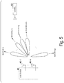
- Fig. 5 is a diagram illustrating p beacons B(1), ..., B(p) transmitted from the base station 40 (where p is an integer of 2 or more).
- the accommodation station 20 generates p beacons B(1), ..., B(p) as RF signals.
- the optical combiner 22 of the accommodation station 20 wavelength-multiplexes the optically modulated beacons B(j) of wavelengths ⁇ 11 , ..., ⁇ 1n which have been phase-adjusted by the phase adjustment unit 21 and transmits the wavelength-multiplexed optically modulated beacon B(j) up to the base station 40 through the optical fiber 30.
- the optical demultiplexer 41 of the base station 40 demultiplexes the wavelength-multiplexed optical signal transmitted through the optical fiber 30 into the optically modulated beacons B(j) of wavelengths ⁇ 11 , ..., ⁇ 1n .
- the O/E converter 42-i converts an optically modulated beacon B(j) of wavelength ⁇ 1i from an optical signal into a beacon B(j) of an electrical signal and the antenna element 43-i radiates the optically modulated beacon B(j) of wavelength ⁇ 1i which has been converted into the electrical signal.
- beacons B(j) are radiated from the antenna elements 43-1, ..., 43-n.
- the base station 40 converts the beacon number information fed back from the terminal 50 from electrical signals to optical signals through the E/O converters 44-1, ..., 44-n and wavelength-combines the optical signals through the optical combiner 45 as they are, and then transmits the wavelength-combined optical signal to the accommodation station 20 through the optical fiber 30.
- the phase adjustment unit 24 of the accommodation station 20 obtains received powers of q pieces of received beacon number information while performing phase adjustment using different values ⁇ 21 , ..., ⁇ 2q as the respective values of ⁇ 2 for the q pieces of received beacon number information.
- the accommodation station 20 determines the value of ⁇ 1 based on the received beacon number information to determine the beam direction of transmitting antennas. That is, if the beacon number information is j, the accommodation station 20 determines that the value of ⁇ 1 is ⁇ 1j .
- Fig. 6 is a diagram illustrating a process of determining beam directions in the wireless communication system 10.
- Fig. 6 illustrates the above operations of the accommodation station 20, the base station 40, and the terminal 50 on the same time axis.
- the accommodation station 20 generates optically modulated beacons B(1), ..., B(p) which have been phase-adjusted respectively using ⁇ 11 , ..., ⁇ 1p as ⁇ 1 and transmits them to the base station 40 (step S11).
- the base station 40 O/E converts optically modulated received beacons B(1), ..., B(p) into RF signals (step S12) and transmits the beacons B(1), ..., B(p) which have been converted into RF signals at different timings (step S13).
- the terminal 50 transmits beacon number information that identifies the selected beacon B(j) to the base station 40 q times (step S15).
- the base station 40 E/O converts q pieces of received beacon number information (step S16) and transmits them to the accommodation station 20 (step S17).
- the base station 40 only performs O/E and E/O conversion of signals received from the accommodation station 20 and the terminal 50, and basically does not need to perform any phase adjustment control.
- Fig. 7 is a block diagram illustrating the configuration of the accommodation station 20, where only functional blocks relating to the present embodiment are extracted and illustrated.
- the accommodation station 20 includes a transmission unit 210, a transmission phase control unit 220, a reception unit 230, a reception phase control unit 240, and an optical circulator 250.
- the transmission unit 210 generates optically modulated transmission signals of wavelengths ⁇ 11 , ..., ⁇ 1n .
- the transmission unit 210 adjusts the phases of optically modulated signals into which light of the wavelengths is modulated with an RF signal.
- a first transmission unit 211 illustrated in Fig. 8 which will be described later can be used as the transmission unit 210.
- the transmission unit 210 adjusts the phases of RF signals into which an RF signal is split for use in modulation of light of the wavelengths and then modulates light of the wavelengths with the phase-adjusted RF signals.
- a second transmission unit 212 illustrated in Fig. 9 which will be described later can be used as the transmission unit 210.
- the transmission phase control unit 220 instructs the transmission unit 210 with the magnitudes of phase adjustment.
- the reception unit 230 adjusts the phases of optically modulated received signals of wavelengths ⁇ 21 , ..., ⁇ 2n and obtains demodulated signals. For phase adjustment of the optically modulated received signals, the reception unit 230 adjusts the phases of demultiplexed optically modulated signals. In this case, a first reception unit 231 illustrated in Fig. 10 which will be described later can be used as the reception unit 230. Alternatively, for phase adjustment of the optically modulated received signals, the reception unit 230 adjusts the phases of RF signals obtained through O/E conversion of the demultiplexed optically modulated signals. In this case, a second reception unit 232 illustrated in Fig. 11 which will be described later can be used as the reception unit 230. The reception phase control unit 240 instructs the reception unit 230 with the magnitudes of phase adjustment.
- the optical circulator 250 receives as an input an optically modulated transmission signal output by the transmission unit 210 and outputs it to the optical fiber 30 and receives as an input an optically modulated received signal transmitted through the optical fiber 30 and outputs it to the reception unit 230.
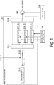
- Fig. 8 is a block diagram illustrating the configuration of the first transmission unit 211.
- the first transmission unit 211 includes a multi-wavelength light source 2111, an optical modulation unit 2112, an optical demultiplexer 2113, phase adjustment units 2114-2, ..., 2114-n, and an optical combiner 2115.
- the multi-wavelength light source 2111 outputs light of wavelengths ⁇ 11 , ..., ⁇ 1n .
- the optical modulation unit 2112 modulates the light of wavelengths ⁇ 11 , ..., ⁇ 1n output by the multi-wavelength light source 2111 with an RF signal.
- the optical demultiplexer 2113 splits optically modulated signals of wavelengths ⁇ 11 , ..., ⁇ 1n .
- the phase adjustment units 2114-2, ..., 2114-n correspond to the phase adjustment unit 21 in Fig. 2 .
- the optical combiner 2115 corresponds to the optical combiner 22 in Fig. 2 .
- the optical combiner 2115 combines the optically modulated signal of ⁇ 11 output by the optical demultiplexer 2113 and the optically modulated signals of ⁇ 12 , ..., ⁇ 1n output by the phase adjustment units 2114-2, ..., 2114-n and outputs the combined optically modulated signal to the optical circulator 250.
- the optical circulator 250 outputs the combined optically modulated signal to the optical fiber 30.
- Fig. 9 is a block diagram illustrating the configuration of the second transmission unit 212.
- the second transmission unit 212 includes a multi-wavelength light source 2121, an optical demultiplexer 2122, a splitting unit 2123, phase adjustment units 2124-2, ..., 2124-n, optical modulation units 2125-1, ..., 2125-n, and an optical combiner 2126.
- the multi-wavelength light source 2121 outputs light of wavelengths ⁇ 11 , ..., ⁇ 1n .
- the optical demultiplexer 2122 splits optically modulated signals of wavelengths ⁇ 11 , ..., ⁇ 1n .
- the splitting unit 2123 splits an RF signal into n RF signals and outputs the RF signals to the optical modulation unit 2125-1 and the phase adjustment units 2124-2, ..., 2124-n.
- the phase adjustment units 2124-2, ..., 2124-n correspond to the phase adjustment unit 21 in Fig. 2 .
- the optical modulation unit 2125-1 modulates light of wavelength ⁇ 11 demultiplexed by the optical demultiplexer 2122 with an RF signal and outputs the modulated light to the optical combiner 2126.
- the optical combiner 2126 corresponds to the optical combiner 22 in Fig. 2 .
- the optical combiner 2126 combines the optically modulated signals of ⁇ 11 , ..., ⁇ 1n output by the optical modulation units 2125-1, ..., 2125-n and outputs the combined optically modulated signal to the optical circulator 250.
- the optical circulator 250 outputs the combined optically modulated signal to the optical fiber 30.
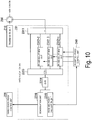
- Fig. 10 is a block diagram illustrating the configuration of the first reception unit 231.
- the first reception unit 231 includes an optical demultiplexer 2311, phase adjustment units 2312-2, ..., 2312-n, an optical combiner 2313, an O/E converter 2314, a received power calculation unit 2315, and a demodulation unit 2316.
- the optical demultiplexer 2311 receives an optically modulated received signal output from the base station 40 through the optical circulator 250 and splits it into optically modulated signals of wavelengths ⁇ 22 , ..., ⁇ 2n .
- the phase adjustment units 2312-2, ..., 2312-n correspond to the phase adjustment unit 24 in Fig. 4 .
- the optical combiner 2313 combines an optically modulated signal of wavelength ⁇ 21 output by the optical demultiplexer 2311 and optically modulated signals of wavelengths ⁇ 22 , ..., ⁇ 2n output by the phase adjustment units 2312-2, ..., 2312-n and outputs the combined optically modulated signals to the O/E converter 2314.
- the O/E converter 2314 outputs the optically modulated signals combined by the optical combiner 2313 as electrical signals and outputs the electrical signals to the received power calculation unit 2315 and the demodulation unit 2316.
- the received power calculation unit 2315 calculates the received powers of the electrical signals input from the O/E converter 2314 and outputs the calculation result to the reception phase control unit 240.
- the demodulation unit 2316 demodulates received signals which have been converted into the electrical signals. Upon obtaining beacon number information transmitted by the terminal 50 through demodulation, the demodulation unit 2316 outputs the obtained beacon number information to the transmission phase control unit 220.
- Fig. 11 is a block diagram illustrating the configuration of the second reception unit 232.
- the second reception unit 232 includes an optical demultiplexer 2321, O/E converters 2322-1, ..., 2322-n, phase adjustment units 2323-2, ..., 2323-n, a received power calculation unit 2324, and a demodulation unit 2325.
- the optical demultiplexer 2321 receives an optically modulated received signal output by the base station 40 through the optical circulator 250 and splits it into optically modulated signals of wavelengths ⁇ 22 , ..., ⁇ 2n .
- the received power calculation unit 2324 calculates a received power using an electrical signal output by the O/E converter 2322-1 and electrical signals output by the phase adjustment units 2323-2, ..., 2323-n and outputs the calculation result to the reception phase control unit 240.
- the demodulation unit 2325 demodulates a signal transmitted from the terminal 50 using the electrical signal output by the O/E converter 2322-1 and the electrical signals output by the phase adjustment units 2323-2, ..., 2323-n. Upon obtaining beacon number information transmitted by the terminal 50 through demodulation, the demodulation unit 2325 outputs the obtained beacon number information to the transmission phase control unit 220.
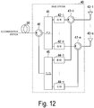
- Fig. 12 is a block diagram illustrating the configuration of the base station 40, where only functional blocks relating to the present embodiment are extracted and illustrated.
- the base station 40 includes an optical demultiplexer 41, O/E converters 42-1, ..., 42-n, antenna elements 43-1, ..., 43-n, E/O converters 44-1, ..., 44-n, an optical combiner 45, an optical circulator 46, and electrical circulators 47-1, ..., 47-n.
- the optical combiner 45 outputs an optically modulated received signal obtained by combining the optically modulated signals of wavelengths ⁇ 21 , ..., ⁇ 2n output from the E/O converters 44-1, ..., 44-n.
- the optical circulator 46 receives as an input an optically modulated transmission signal transmitted through the optical fiber 30 and outputs it to the optical demultiplexer 41.
- the optical circulator 46 also receives as an input a combined optically modulated received signal obtained by the optical combiner 45 and outputs it to the optical fiber 30.
- Fig. 13 is a block diagram illustrating the configuration of the terminal 50, where only functional blocks relating to the present embodiment are extracted and illustrated.
- the terminal 50 includes antenna elements 51-1, ..., 51-m (m is an integer of 1 or more), electrical circulators 52-1, ..., 52-m, a receiving antenna control unit 53, a received power calculation unit 54, a demodulation unit 55, a maximum received power beacon selection unit 56, and a transmitting antenna control unit 57.
- the antenna elements 51-1, ..., 51-m output wirelessly received RF signals to the receiving antenna control unit 53.
- the antenna elements 51-1, ..., 51-m also radiate RF signals output by the transmitting antenna control unit 57.
- the receiving antenna control unit 53 has a function of controlling beamforming of the receiving antennas of the terminal 50 and the like.
- the received power calculation unit 54 calculates received powers of received beacons and outputs the calculation result to the maximum received power beacon selection unit 56.
- the demodulation unit 55 demodulates received signals. Upon demodulating beacons, the demodulation unit 55 outputs beacon number information obtained from information contained in the beacons to the maximum received power beacon selection unit 56.
- the maximum received power beacon selection unit 56 acquires beacon number information of a beacon having the maximum received power based on the received powers calculated by the received power calculation unit 54 and outputs the beacon number information to the transmitting antenna control unit 57.
- the transmitting antenna control unit 57 performs control such that RF signals in which the beacon number information is set are transmitted p times through the antenna elements 51-1, ..., 51-m.
- the transmitting antenna control unit 57 also has a function of controlling beamforming of the transmitting antennas of the terminal 50 and the like.
- the first transmission unit 211 illustrated in Fig. 8 and the first reception unit 231 illustrated in Fig. 10 are used as the transmission unit 210 and the reception unit 230 of the accommodation station 20.
- the accommodation station 20 adjusts the phases of optically modulated signals of wavelengths for phase adjustment of optically modulated transmission signals and optically modulated received signals.
- the multi-wavelength light source 2111 of the accommodation station 20 generates optical signals of n different wavelengths ⁇ 11 , ..., ⁇ 1n .
- the optical signals of wavelengths ⁇ 11 , ..., ⁇ 1n are input to the single optical modulation unit 2112.
- the optical modulation unit 2112 modulates the optical signals of wavelengths ⁇ 11 , ..., ⁇ 1n input from the multi-wavelength light source 2111 using an input RF signal and outputs optically modulated signals of wavelengths ⁇ 11 , ..., ⁇ 1n .
- a signal obtained by modulating an optical signal with an RF signal is a double side band (DSB) signal.
- the optical modulation unit 2112 may have a function of handling fading due to chromatic dispersion, such as using single side band (SSB) signals or two-tone signals as optically modulated signals.
- SSB single side band
- the optical demultiplexer 2113 fixedly splits the optically modulated signals of wavelengths ⁇ 11 , ..., ⁇ 1n .
- the optically modulated signal of wavelength ⁇ 11 is sent to the optical combiner 2115 as it is, and the optically modulated signals of wavelengths ⁇ 12 , ..., ⁇ 1n are sent to the phase adjustment units 2114-2, ..., 2114-n, respectively.
- the transmission phase control unit 220 inputs values of ⁇ 1 to the n-1 phase adjustment units 2114-2, ..., 2114-n.
- the optical combiner 2115 combines the optically modulated signal of wavelength ⁇ 11 and the phase-adjusted optically modulated signals of wavelengths ⁇ 12 , ..., ⁇ 1n .
- the combined optically modulated signal is sent to the base station 40 via the optical circulator 250 and the optical fiber 30. At this time, it is unnecessary to know distance information of the optical fiber 30.
- optically modulated signals of wavelengths ⁇ 11 , ..., ⁇ 1n When optically modulated signals of wavelengths ⁇ 11 , ..., ⁇ 1n are transmitted through an optical fiber, they undergo different delay differences under the influence of chromatic dispersion and thus experience different phase rotations. Because the wavelengths ⁇ 11 , ..., ⁇ 1n are arranged at equal intervals which are sufficiently small wavelength intervals, the delay differences due to chromatic dispersion can also be made at equal intervals and the amounts of phase rotation of the RF signals of the optically modulated signals of wavelengths ⁇ 11 , ..., ⁇ 1n are also at equal intervals.
- the amounts of phase rotation ⁇ 11 , ..., ⁇ 1n of the RF signals are constants because the wavelengths ⁇ 11 , ..., ⁇ 1n are fixed. However, the values of the amounts of phase rotation ⁇ 11 , ..., ⁇ 1n of the RF signals cannot be specifically obtained if the distance information of the optical fiber 30 is unknown.
- optically modulated signals of wavelengths ⁇ 11 , ..., ⁇ 1n which have been transmitted from the accommodation station 20 to the base station 40 through the optical fiber are fixedly split by the optical demultiplexer 41 after passing through the optical circulator 46 and are sent to the antenna elements 43-1, ..., 43-n. At this time, it is unnecessary to control the optical demultiplexer 41 because the optical splitting is fixed.
- the O/E converters 42-1, ..., 42-n convert the optically modulated signals of wavelengths ⁇ 11 , ..., ⁇ 1n into RF signals through O/E conversion, respectively.
- the wavelength of the transmitted RF signal is ⁇ RF1 and the transmission beam direction ⁇ is defined as illustrated in Fig. 3 assuming that the antenna elements 43-1, ..., 43-n are arranged at equal intervals d, a transmission beam is formed in a direction satisfying the above equation (1).
- the wavelength ⁇ RF1 of the transmitted RF signal and the antenna element interval d are known constants. Because the wavelengths ⁇ 11 , ..., ⁇ 1n are fixed, ⁇ 1 is also a constant. However, if the distance information of the optical fiber 30 is unknown, the values of the amounts of phase rotation ⁇ 11 , ..., ⁇ 1n of the RF signals cannot be specifically obtained and a specific value of ⁇ 1 cannot be obtained. Thus, ⁇ 1 alone determines the transmission beam direction ⁇ . This means that a transmission beam can be formed in a certain direction ⁇ by changing the value of ⁇ 1 , while the specific direction is unknown. However, basically, there is no need to control the base station 40 in forming the transmission beam because the accommodation station 20 alone controls ⁇ 1 .
- the direction ⁇ of the transmission beam formed by the base station 40 is unknown as described above.
- feedback from the terminal 50, which is a communication partner of the base station 40 is required to determine the transmission beam direction.
- a process of determining the transmission beam direction will be described in detail after beamforming of the receiving antennas is described.
- the received RF signals are sent to the E/O converters 44-1, ..., 44-n via the electrical circulators 47-1, ..., 47-n.
- the E/O converters 44-1, ..., 44-n corresponding to the antenna elements 43-1, ..., 43-n modulate optical signals of wavelengths ⁇ 21 , ..., ⁇ 2n with the received RF signals and output optically modulated signals of wavelengths ⁇ 21 , ..., ⁇ 2n .
- a signal from the terminal 50 is assumed to arrive at the base station 40 in the direction ⁇ as illustrated in Fig. 3 .
- the optical combiner 45 combines the optically modulated signals of wavelengths ⁇ 21 , ..., ⁇ 2n .
- the combined optically modulated signal is sent to the accommodation station 20 via the optical circulator 46 and the optical fiber 30. At this time, it is unnecessary to know distance information of the optical fiber 30.
- optically modulated signals of wavelengths ⁇ 21 , ..., ⁇ 2n When optically modulated signals of wavelengths ⁇ 21 , ..., ⁇ 2n are transmitted through an optical fiber, they undergo different delay differences under the influence of chromatic dispersion and thus experience different phase rotations. Because the wavelengths ⁇ 21 , ..., ⁇ 2n are arranged at equal intervals which are sufficiently small wavelength intervals, the delay differences due to chromatic dispersion can be made at equal intervals and the amounts of phase rotation of the RF signals of the optically modulated signals of wavelengths ⁇ 21 , ..., ⁇ 2n are also at equal intervals.
- the amounts of phase rotation ⁇ 21 , ..., ⁇ 2n of the RF signals are constants because the wavelengths ⁇ 21 , ..., ⁇ 2n are fixed. However, the values of the amounts of phase rotation ⁇ 21 , ..., ⁇ 2n of the RF signals cannot be specifically obtained if the distance information of the optical fiber 30 is unknown.
- the phases of the RF signals of the optically modulated signals of wavelengths ⁇ 21 , ⁇ 22 , ⁇ 23 , ..., ⁇ 2n received by the accommodation station 20 are ⁇ 21 + ⁇ 21 , ⁇ 21 + ⁇ 21 + ⁇ 2 - ⁇ 2 , ⁇ 21 + ⁇ 21 + 2( ⁇ 2 - ⁇ 2 ), ..., ⁇ 21 + ⁇ 21 + (n - 1)( ⁇ 2 - ⁇ 2 ).
- the optically modulated signals of wavelengths ⁇ 21 , ..., ⁇ 2n that have been transmitted from the base station 40 through the optical fiber pass through the optical circulator 250 of the accommodation station 20 and are fixedly split by the optical demultiplexer 2311 of the first reception unit 231.
- the optically modulated signal of wavelength ⁇ 21 is sent to the optical combiner 2313 as it is and the optically modulated signals of wavelengths ⁇ 22 , ..., ⁇ 2n are sent to the phase adjustment units 2312-2, ..., 2312-n, respectively. At this time, it is unnecessary to control the optical demultiplexer 2311 because the optical splitting is fixed.
- the reception phase control unit 240 inputs values of ⁇ 2 to the n - 1 phase adjustment units 2312-2, ..., 2312-n.
- the phases of the RF signals of the optically modulated signals of wavelengths ⁇ 21 , ⁇ 22 , ⁇ 23 , ..., ⁇ 2n are ⁇ 21 + ⁇ 21 , ⁇ 21 + ⁇ 21 + ⁇ 2 - ⁇ 2 + ⁇ 2 , ⁇ 21 + ⁇ 21 + 2( ⁇ 2 - ⁇ 2 + ⁇ 2 ), ..., ⁇ 21 + ⁇ 21 + (n - 1)( ⁇ 2 - ⁇ 2 + ⁇ 2 ), respectively.
- ⁇ 2 ⁇ 2 - ⁇ 2
- the phases of the RF signals of the optically modulated signals of wavelengths ⁇ 21 , ..., ⁇ 2n are in phase at ⁇ 21 + ⁇ 21 and thus a receiving antenna beam is formed in the direction ⁇ .
- there is a need to scan the values of ⁇ 2 to obtain a value of ⁇ 2 ⁇ 2 - ⁇ 2 that maximizes the received power.
- a variable that determines the reception beam direction ⁇ is only ⁇ 2 and the reception beam direction ⁇ can be changed by changing the value of ⁇ 2 .
- the base station 40 in controlling the reception beam direction because the accommodation station 20 controls ⁇ 2 .
- the process of determining beam directions of the receiving/transmitting antennas is similar to that of Fig. 6 described above.
- the accommodation station 20 generates p beacons B(1), ..., B(p) as RF signals and inputs them to the optical modulation unit 2112 in order.
- the optical demultiplexer 2113 splits the optically modulated beacons B(j) of wavelengths ⁇ 11 , ..., ⁇ 1n .
- the optically modulated beacon B(j) of wavelength ⁇ 11 is output to the optical combiner 2115 as it is.
- the transmission phase control unit 220 instructs the phase adjustment units 2114-2, ..., 2114-n with a corresponding one of the different values ⁇ 11 , ..., ⁇ 1p which are values of ⁇ 1 corresponding to the p optically modulated beacons B(1), ..., B(p).
- the optical combiner 2115 combines the phase-adjusted optically modulated beacons B(j) of wavelengths ⁇ 11 , ..., ⁇ 1n .
- the combined optically modulated beacon B(j) is transmitted through the optical fiber, then O/E converted at the base station 40, and is radiated from the antenna elements 43-1, ..., 43-n as beacons B(j).
- the beacons B(j) are radiated in a direction ⁇ j that satisfies the above equation (3).
- Performing the above operations for the p beacons B(1), ..., B(p) allows the wireless communication system 10 to transmit the beacons B(1), ..., B(p) from the base station 40 in p different directions ⁇ 1 , ..., ⁇ p , respectively, as illustrated in Fig. 5 (steps S11 to S13 in Fig. 6 ).
- the antenna elements 51-1, ..., 51-m of the terminal 50 receive the p beacons B(1), ..., B(p) from the base station 40.
- the receiving antenna control unit 53 outputs the p beacons B(1), ..., B(p) received by the antenna elements 51-1, ..., 51-m to the received power calculation unit 54 and the demodulation unit 55.
- the received power calculation unit 54 calculates the received powers of the received p beacons B(1), ..., B(p) and outputs the calculation result.
- the demodulation unit 55 demodulates the received p beacons B(1), ..., B(p) and outputs beacon numbers.
- the maximum received power beacon selection unit 56 selects a beacon number with the maximum received power and outputs corresponding beacon number information (step S14 in Fig. 6 ).
- the transmitting antenna control unit 57 performs control such that the beacon number information output by the maximum received power beacon selection unit 56 is transmitted to the base station 40 through the antenna elements 51-1, ..., 51-m.
- the terminal 50 transmits this beacon number information q times (step S15 in Fig. 6 ).
- the E/O converters 44-1, ..., 44-n of the base station 40 E/O convert the beacon number information which the antenna elements 43-1, ..., 43-n have received from the terminal 50 (step S16 in Fig. 6 ).
- the optical combiner 45 combines optically modulated beacon number information of wavelengths ⁇ 21 , ..., ⁇ 2n obtained through the E/O conversion and transmits the combined information to the accommodation station 20. Because the beacon number information has been transmitted from the terminal 50 q times, the base station 40 transmits the optically modulated beacon number information to the accommodation station 20 q times at different timings (step S17 in Fig. 6 ).
- the optical demultiplexer 2311 of the accommodation station 20 splits the optically modulated beacon number information transmitted from the base station 40 into optically modulated beacon number information of wavelengths ⁇ 21 , ..., ⁇ 2n .
- the optically modulated beacon number information of wavelength ⁇ 21 is sent to the optical combiner 2313 as it is and the optically modulated beacon number information of the wavelengths ⁇ 22 , ..., ⁇ 2n is phase-adjusted by the phase adjustment units 2312-2, ..., 2312-n, respectively.
- the phase adjustment units 2312-2, ..., 2312-n adjust the phases of q pieces of received the optically modulated beacon number information using ⁇ 21 , ..., ⁇ 2q , which are different values of ⁇ 2 , under the control of the reception phase control unit 240. Therefore, each time the optically modulated beacon number information is received, the reception phase control unit 240 changes the value of ⁇ 2 in the order of ⁇ 21 , ..., ⁇ 2q and instructs the phase adjustment units 2312-2, ..., 2312-n with the changed value of ⁇ 2 .
- the optical combiner 2313 combines the optically modulated beacon number information of wavelength ⁇ 21 and the optically modulated beacon number information of wavelengths ⁇ 22 , ..., ⁇ 2n which have been phase-adjusted respectively by the phase adjustment units 2312-2, ..., 2312-n and outputs the combined optically modulated beacon number information to the O/E converter 2314.
- the O/E converter 2314 O/E converts the combined optically modulated beacon number information to obtain beacon number information.
- the O/E converter 2314 outputs the beacon number information to the received power calculation unit 2315 and the demodulation unit 2316.
- the received power calculation unit 2315 receives q pieces of beacon number information on which different phase adjustments have been performed, calculates their received powers, and notifies the reception phase control unit 240 of the calculated received powers.
- the reception phase control unit 240 determines a value of ⁇ 2 which maximizes the received power based on the notified received powers. In this way, the accommodation station 20 receives q pieces of beacon number information while scanning the values of ⁇ 2 and selects a value of ⁇ 2 which maximizes the received power to determine the value of ⁇ 2 . This determines the beam direction of receiving antennas (step S18 in Fig. 6 ).
- the reception phase control unit 240 controls the first reception unit 231 such that it uses the determined value of ⁇ 2 when receiving a signal from the terminal 50.
- the demodulation unit 2316 demodulates received beacon number information and outputs the demodulated beacon number information to the transmission phase control unit 220.
- the transmission phase control unit 220 determines a value of ⁇ 1 based on the beacon number information. This determines the beam direction of transmitting antennas (step S19 in Fig. 6 ).
- the transmission phase control unit 220 controls the first transmission unit 211 such that it uses the determined value of ⁇ 1 when transmitting a signal to the terminal 50.
- the base station 40 only needs to perform O/E and E/O conversion of signals received from the accommodation station 20 and the terminal 50 and does not need to perform control for the beam direction control.
- the second transmission unit 212 illustrated in Fig. 9 and the second reception unit 232 illustrated in Fig. 11 are used as the transmission unit 210 and the reception unit 230 of the accommodation station 20.
- the accommodation station 20 adjusts the phases of RF signals of the optically modulated transmission signals and optically modulated received signals.
- the multi-wavelength light source 2121 of the accommodation station 20 generates optical signals of n different wavelengths ⁇ 11 , ..., ⁇ 1n .
- the optical demultiplexer 2122 splits optical signals of wavelengths ⁇ 11 , ..., ⁇ 1n and inputs them to the optical modulation units 2125-1, ..., 2125-n, respectively.
- the transmission phase control unit 220 inputs values of ⁇ 1 to the n - 1 phase adjustment units 2124-2, ..., 2124-n.
- the splitting unit 2123 splits an RF signal into n RF signals and outputs the RF signals to the optical modulation unit 2125-1 and the phase adjustment units 2124-2, ..., 2124-n.
- the optical modulation unit 2125-1 modulates the optical signal of wavelength ⁇ 11 with the RF signal and outputs an optically modulated signal of wavelength X n .
- the optical modulation units 2125-1, ..., 2125-n may have a function of handling fading due to chromatic dispersion, similar to the operation example 1.
- the optical combiner 2115 combines the optically modulated signals of wavelengths ⁇ 11 , ..., ⁇ 1n .
- the combined optically modulated signal is sent to the base station 40 via the optical circulator 250 and the optical fiber 30. At this time, it is unnecessary to know distance information of the optical fiber 30.
- optically modulated signals of wavelengths ⁇ 11 , ..., ⁇ 1n are transmitted through an optical fiber, they undergo different delay differences under the influence of chromatic dispersion and thus experience different phase rotations. Because the wavelengths ⁇ 11 , ..., ⁇ 1n are arranged at equal intervals which are sufficiently small wavelength intervals, the delay differences due to chromatic dispersion can also be made at equal intervals and the amounts of phase rotation of the RF signals of the optically modulated signals of wavelengths ⁇ 11 , ..., ⁇ 1n are also at equal intervals.
- the amounts of phase rotation ⁇ 11 , ..., ⁇ 1n of the RF signals are constants because the wavelengths ⁇ 11 , ..., ⁇ 1n are fixed. However, the values of the amounts of phase rotation ⁇ 11 , ..., ⁇ 1n of the RF signals cannot be specifically obtained if the distance information of the optical fiber is unknown.
- the operations of the base station 40 and the terminal 50 are similar to those of the operation example 1. That is, the optically modulated signals of wavelengths ⁇ 11 , ..., ⁇ 1n which have been transmitted from the accommodation station 20 to the base station 40 through the optical fiber are fixedly split by the optical demultiplexer 41 after passing through the optical circulator 46. It is unnecessary to control the optical demultiplexer 41 because the optical splitting is fixed.
- the O/E converters 42-1, ..., 42-n convert the optically modulated signals of wavelengths ⁇ 11 , ..., ⁇ 1n split by the optical demultiplexer 41 into RF signals, respectively.
- the wavelength of the transmitted RF signal is ⁇ RF1 and the transmission beam direction ⁇ is defined as illustrated in Fig. 3 assuming that the antenna elements 43-1, ..., 43-n are arranged at equal intervals d, a transmission beam is formed in a direction satisfying the above equation (1).
- the wavelength ⁇ RF1 of the transmitted RF signal and the antenna element interval d are known constants. Because the wavelengths ⁇ 11 , ..., ⁇ 1n are fixed, ⁇ 1 is also a constant. However, if the distance information of the optical fiber 30 is unknown, the values of the amounts of phase rotation ⁇ 11 , ..., ⁇ 1n of the RF signals cannot be specifically obtained and a specific value of ⁇ 1 cannot be obtained. Thus, ⁇ 1 alone determines the transmission beam direction ⁇ . This means that a transmission beam can be formed in a certain direction ⁇ by changing the value of ⁇ 1 , while the specific direction is unknown. However, basically, there is no need to control the base station in forming the transmission beam because the accommodation station 20 alone controls ⁇ 1 .
- the direction ⁇ of the transmission beam formed by the base station 40 is unknown.
- feedback from the terminal 50, which is a communication partner of the base station 40 is required to determine the transmission beam direction.
- a process of determining the transmission beam direction will be described in detail after beamforming of the receiving antennas is described.
- the received RF signals are sent to the E/O converters 44-1, ..., 44-n via the electrical circulators 47-1, ..., 47-n.
- the E/O converters 44-1, ..., 44-n modulate optical signals of wavelengths ⁇ 21 , ..., ⁇ 2n with the received RF signals and output optically modulated signals of wavelengths ⁇ 21 , ..., ⁇ 2n .
- a signal from the terminal 50 is assumed to arrive at the base station 40 in the direction ⁇ as illustrated in Fig. 3 .
- the phase of an RF signal received by the antenna element 43-i is ⁇ 2i
- the E/O converter 44-i corresponding to the antenna element 43-i modulates an optical signal of wavelength ⁇ 2i with a received RF signal having a phase of ⁇ 2i and outputs an optically modulated signal of wavelength ⁇ 2i .
- the optical combiner 45 combines the optically modulated signals of wavelengths ⁇ 21 , ..., ⁇ 2n .
- the combined optically modulated signal is sent to the accommodation station 20 via the optical circulator 46 and the optical fiber 30. At this time, it is unnecessary to know distance information of the optical fiber 30.
- optically modulated signals of wavelengths ⁇ 21 , ..., ⁇ 2n are transmitted through an optical fiber, they undergo different delay differences under the influence of chromatic dispersion and thus experience different phase rotations. Because the wavelengths ⁇ 21 , ..., ⁇ 2n are arranged at equal intervals which are sufficiently small wavelength intervals, the delay differences due to chromatic dispersion can be made at equal intervals and the amounts of phase rotation of the RF signals of the optically modulated signals of wavelengths ⁇ 21 , ..., ⁇ 2n are also at equal intervals.
- the amounts of phase rotation ⁇ 21 , ..., ⁇ 2n of the RF signals are constants because the wavelengths ⁇ 21 , ..., ⁇ 2n are fixed.
- the values of the amounts of phase rotation ⁇ 21 , ..., ⁇ 2n of the RF signals cannot be specifically obtained if the distance information of the optical fiber 30 is unknown.
- the phases of the RF signals of the optically modulated signals of wavelengths ⁇ 21 , ⁇ 22 , ⁇ 23 , ..., ⁇ 2n received by the accommodation station 20 are ⁇ 21 + ⁇ 21 , ⁇ 21 + ⁇ 21 + ⁇ 2 - ⁇ 2 , ⁇ 21 + ⁇ 21 + 2( ⁇ 2 - ⁇ 2 ), ..., ⁇ 21 + ⁇ 21 + (n - 1)( ⁇ 2 - ⁇ 2 ).
- the optically modulated signals of wavelengths ⁇ 21 , ..., ⁇ 2n that have been transmitted from the base station 40 through the optical fiber pass through the optical circulator 250 of the accommodation station 20 and are fixedly split by the optical demultiplexer 2321 of the second reception unit 232.
- the O/E converters 2322-1, ..., and 2322-n perform O/E conversion of the optically modulated signals of wavelengths ⁇ 21 , ..., ⁇ 2n , respectively, to obtain received signals (1), ..., (n).
- the received signals (2), ..., (n) are input to the phase adjustment units 2323-2, ..., 2323-n, respectively.
- the reception phase control unit 240 inputs values of ⁇ 2 to the n - 1 phase adjustment units 2323-2, ..., 2323-n.
- the phases of the RF signals of the received signals (1), (2), (3), ..., (n) are ⁇ 21 + ⁇ 21 , ⁇ 21 + ⁇ 21 + ⁇ 2 - ⁇ 2 + ⁇ 2 , ⁇ 21 + ⁇ 21 + 2( ⁇ 2 - ⁇ 2 + ⁇ 2 ), ..., ⁇ 21 + ⁇ 21 + (n - 1)( ⁇ 2 - ⁇ 2 + ⁇ 2 ), respectively.
- ⁇ 2 ⁇ 2 - ⁇ 2
- the phases of the RF signals of the received signals (1), (2), (3), ..., (n) are in phase at ⁇ 21 + ⁇ 21 and thus a receiving antenna beam is formed in the direction ⁇ .
- ⁇ 2 ⁇ 2 - ⁇ 2 that maximizes the received power.
- a variable that determines the reception beam direction ⁇ is only ⁇ 2 and the reception beam direction ⁇ can be changed by changing the value of ⁇ 2 , similar to the operation example 1. Basically, there is no need to control the base station 40 in controlling the reception beam direction because the accommodation station 20 controls ⁇ 2 .
- the process of determining beam directions of the receiving/transmitting antennas is similar to that of Fig. 6 described above.
- the accommodation station 20 generates p beacons B(1), ..., B(p) as RF signals and the splitting unit 2123 inputs them to the optical modulation unit 2125-1 and the phase adjustment units 2124-2, ..., 2124-n in order.
- the transmission phase control unit 220 instructs the phase adjustment units 2124-2, ..., 2124-n with a corresponding one of the different values ⁇ 11 , ..., ⁇ 1p which are values of ⁇ 1 corresponding to the p beacons B(1), ..., B(p).
- the optical modulation unit 2125-1 modulates the optical signal of wavelength ⁇ 1 using the beacon B(j) and outputs an optically modulated beacon B(j) of wavelength ⁇ 11 .
- the optical combiner 2126 combines the phase-adjusted optically modulated beacons B(j) of wavelengths ⁇ 11 , ..., ⁇ 1n .
- the combined optically modulated beacon B(j) is transmitted through the optical fiber, then O/E converted at the base station 40, and is radiated from the antenna elements 43-1, ..., 43-n as beacons B(j).
- the beacons B(j) are radiated in a direction ⁇ j that satisfies the above equation (3).
- performing the above operations for the p beacons B(1), ..., B(p) allows the wireless communication system 10 to transmit the beacons B(1), ..., B(p) from the base station 40 in p different directions ⁇ 1 , ..., ⁇ p , respectively, as illustrated in Fig. 5 (steps S11 to S13 in Fig. 6 ).
- the terminal 50 operates similar to the operation example 1. That is, the receiving antenna control unit 53 of the terminal 50 outputs the p beacons B(1), ..., B(p) received by the antenna elements 51-1, ..., 51-m to the received power calculation unit 54 and the demodulation unit 55.
- the received power calculation unit 54 calculates the received powers of the received p beacons B(1), ..., B(p) and outputs the calculation result.
- the demodulation unit 55 demodulates the received p beacons B(1), ..., B(p) and outputs beacon numbers.
- the maximum received power beacon selection unit 56 selects a beacon number with the maximum received power and outputs corresponding beacon number information (step S14 in Fig. 6 ).
- the transmitting antenna control unit 57 performs control such that the beacon number information output by the maximum received power beacon selection unit 56 is transmitted to the base station 40 through the antenna elements 51-1, ..., 51-m.
- the terminal 50 transmits this beacon number information q times (step S15 in Fig. 6 ).
- the base station 40 E/O converts the beacon number information received from the terminal 50 and transmits optically modulated beacon number information of wavelengths ⁇ 21 , ..., ⁇ 2n to the accommodation station 20 (step S16 in Fig. 6 ). Because the beacon number information has been transmitted from the terminal 50 q times, the base station 40 transmits the optically modulated beacon number information to the accommodation station 20 q times (step S17 in Fig. 6 ).
- the optical demultiplexer 2321 of the accommodation station 20 splits the optically modulated beacon number information transmitted from the base station 40 into optically modulated beacon number information of wavelengths ⁇ 21 , ..., ⁇ 2n .
- the O/E converters 2322-1, ..., 2322-n O/E convert the optically modulated beacon number information of wavelengths ⁇ 21 , ..., ⁇ 2n to obtain received beacon number information (1), ..., (n).
- the received beacon number information (2), ..., (n) is output to the phase adjustment units 2323-2, ..., 2323-n, respectively.
- the phase adjustment units 2323-2, ..., 2323-n adjust the phases of the received beacon number information (2), ..., (n), respectively.
- the phase adjustment units 2323-2, ..., 2323-n adjust the phases of q pieces of received beacon number information using ⁇ 21 , ..., ⁇ 2q , which are different values of ⁇ 2 , under the control of the reception phase control unit 240. Therefore, each time the optically modulated beacon number information is received, the reception phase control unit 240 changes the value of ⁇ 2 in the order of ⁇ 21 , ..., ⁇ 2q and instructs the phase adjustment units 2323-2, ..., 2323-n with the changed value of ⁇ 2 .
- the received beacon number information (1) output by the O/E converter 2322-1 and the received beacon number information (2), ..., (n) which has been phase-adjusted respectively by the phase adjustment units 2323-2, ..., 2323-n are combined and output to the received power calculation unit 2324 and the demodulation unit 2325.
- the received power calculation unit 2324 receives q pieces of beacon number information on which different phase adjustments have been performed, calculates their received powers, and notifies the reception phase control unit 240 of the calculated received powers.
- the reception phase control unit 240 determines a value of ⁇ 2 which maximizes the received power based on the notified received powers. In this way, the accommodation station 20 receives q pieces of beacon number information while scanning the values of ⁇ 2 and selects a value of ⁇ 2 which maximizes the received power to determine the value of ⁇ 2 . This determines the beam direction of receiving antennas (step S18 in Fig. 6 ).
- the reception phase control unit 240 controls the second reception unit 232 such that it uses the determined value of ⁇ 2 when receiving a signal from the terminal 50.
- the demodulation unit 2325 demodulates received beacon number information and outputs the demodulated beacon number information to the transmission phase control unit 220.
- the transmission phase control unit 220 determines a value of ⁇ 1 based on the beacon number information. This determines the beam direction of transmitting antennas (step S19 in Fig. 6 ).
- the transmission phase control unit 220 controls the second transmission unit 212 such that it uses the determined value of ⁇ 1 when transmitting a signal to the terminal 50.
- the base station 40 only needs to perform O/E and E/O conversion of signals received from the accommodation station 20 and the terminal 50 and does not need to perform control for the beam direction control.
- the first transmission unit 211 illustrated in Fig. 8 and the second reception unit 232 illustrated in Fig. 11 are used as the transmission unit 210 and the reception unit 230 of the accommodation station 20.
- the accommodation station 20 adjusts the phases of optically modulated signals for phase adjustment of optically modulated transmission signals and adjusts the phases of RF signals for phase adjustment of optically modulated received signals. That is, the wireless communication system 10 performs operations similar to those of the operation example 1 in the beamforming of transmitting antennas and performs operations similar to those of the operation example 2 in the beamforming of receiving antennas.
- the second transmission unit 212 illustrated in Fig. 9 and the first reception unit 231 illustrated in Fig. 10 are used as the transmission unit 210 and the reception unit 230 of the accommodation station 20.
- the accommodation station 20 adjusts the phases of RF signals for phase adjustment of optically modulated transmission signals and adjusts the phases of optically modulated signals for phase adjustment of optically modulated received signals. That is, the wireless communication system 10 performs operations similar to those of the operation example 2 in the beamforming of transmitting antennas and performs operations similar to those of the operation example 1 in the beamforming of receiving antennas.
- first transmission units 211a, 211b, 211c, and 211d which are modifications of the first transmission unit 211 used as the transmission unit 210 of the accommodation station 20, will be described with reference to Figs. 14 , 15 , 16 , and 17 .
- Fig. 14 is a diagram illustrating the configuration of the first transmission unit 211a.
- the first transmission unit 211a illustrated in Fig. 14 differs from the first transmission unit 211 illustrated in Fig. 8 in that it includes n light sources 2611-1, ..., 2611-n and an optical combiner 2612 instead of the multi-wavelength light source 2111.
- the optical combiner 2612 combines light of the wavelengths ⁇ 11 , ..., ⁇ 1n output respectively by the light sources 2611-1, ..., 2611-n and outputs the combined light to the optical modulation unit 2112.
- Fig. 15 is a diagram illustrating the configuration of the first transmission unit 211b.
- the first transmission unit 211b illustrated in Fig. 15 differs from the first transmission unit 211 illustrated in Fig. 8 in that it includes an optical demultiplexer 2621 and optical modulation units 2622-1, ..., 2622-n instead of the optical modulation unit 2112.
- Fig. 16 is a diagram illustrating the configuration of the first transmission unit 211c.
- the first transmission unit 211c illustrated in Fig. 16 differs from the first transmission unit 211b illustrated in Fig. 15 in that it includes light sources 2611-1, ..., 2611-n instead of the multi-wavelength light source 2111 and the optical demultiplexer 2621.
- Fig. 17 is a diagram illustrating the configuration of the first transmission unit 211d.
- the first transmission unit 211d illustrated in Fig. 17 differs from the first transmission unit 211 illustrated in Fig. 8 in that it includes n direct optical modulation units 2631-1, ..., 2631-n instead of the multi-wavelength light source 2111, the optical modulation unit 2112, and the optical demultiplexer 2113.
- the optical combiner 2115 combines the optically modulated signal of ⁇ 11 output by the direct optical modulation unit 2631-1 and the optically modulated signals of ⁇ 12 to ⁇ 1n output by the phase adjustment units 2114-2, ..., 2114-n and outputs the combined optically modulated signal to the optical circulator 250.
- second transmission units 212a and 212b which are modifications of the second transmission unit 212 used as the transmission unit 210 of the accommodation station 20, will be described with reference to Figs. 18 and 19 below.
- Fig. 18 is a diagram illustrating the configuration of the second transmission unit 212a.
- the second transmission unit 212a illustrated in Fig. 18 differs from the second transmission unit 212 illustrated in Fig. 9 in that it includes n light sources 2711-1, ..., 2711-n instead of the multi-wavelength light source 2121 and the optical demultiplexer 2122.
- Fig. 19 is a diagram illustrating the configuration of the second transmission unit 212b.
- the second transmission unit 212b illustrated in Fig. 19 differs from the second transmission unit 212 illustrated in Fig. 9 in that it includes direct optical modulation units 2721-1, ..., 2721-n instead of the multi-wavelength light source 2121, the optical demultiplexer 2122, and the optical modulation units 2125-1, ..., 2125-n.
- the direct optical modulation unit 2721-1 outputs an optically modulated signal obtained by modulating light of wavelength ⁇ 1i with an RF signal to the optical combiner 2126.
- the optical combiner 2126 combines the optically modulated signals of ⁇ 11 , ..., ⁇ 1n output respectively by the direct optical modulation units 2721-1, ..., 2721-n and outputs the combined optically modulated signal to the optical circulator 250.
- n wavelengths that are set at equal intervals in a range in which chromatic dispersion in the optical fiber between the accommodation station and the base station can be regarded as constant are fixedly assigned to n antenna elements of the base station which are arranged at equal intervals.
- the accommodation station controls transmission and reception beam directions by adjusting the phases of optical signals of the wavelengths or modulated signals that modulate the optical signals of the wavelengths such that the amounts of phase shift of their RF signals are at equal intervals.
- the base station transmits beacon signals a plurality of times while the accommodation station varies the transmission phase shift interval ⁇ 1 , and the terminal transmits information on a beacon signal with the maximum received power a plurality of times.
- the base station receives information on the beacon signal from the terminal and the accommodation station varies the reception phase shift interval ⁇ 2 for information on each received beacon signal to determine a reception phase shift interval ⁇ 2 which maximizes the received power. Further, the accommodation station determines the transmission phase shift interval ⁇ 1 based on the information on the beacon signal received from the terminal.
- a beamforming type RoF system which has a good wavelength utilization efficiency and does not require base station control even if distance information of the optical fiber between the accommodation station and the base station is unclear can be realized at low cost.
- a wireless communication system includes an accommodation station apparatus, a base station apparatus that is connected to the accommodation station apparatus through an optical transmission line and has n antenna elements (where n is an integer of 2 or more), and a terminal that perform wireless communication with the base station apparatus.
- the accommodation station apparatus is the accommodation station 20
- the base station apparatus is the base station 40
- the terminal is the terminal 50
- the optical transmission line is the optical fiber 30.
- the accommodation station apparatus includes a transmission unit, a transmission phase control unit, a reception unit, a reception phase control unit, a transmission phase adjustment amount determination unit, and a reception phase adjustment amount determination unit.
- the transmission unit adjusts phases of optically modulated transmission signals, obtained respectively by modulating light of n different first wavelengths with a transmission signal, by first amounts of phase adjustment corresponding respectively to the n first wavelengths, and outputs a combined optically modulated transmission signal obtained by combining the phase-adjusted optically modulated transmission signals of the n first wavelengths to the optical transmission line.
- the transmission phase control unit controls the transmission unit such that the transmission unit adjusts phases of the p beacons signals by the first amounts of phase adjustment which differ between the p beacon signals.
- the reception unit demultiplexes a combined optically modulated received signal transmitted through the optical transmission line into optically modulated received signals of n different second wavelengths, and converts the demultiplexed optically modulated received signals into electrical signals which have been phase-adjusted by second amounts of phase adjustment corresponding respectively to the n second wavelengths.
- the reception phase control unit controls the reception unit such that the reception unit adjusts phases of the q combined optically modulated received signals by the second amounts of phase adjustment which differ between the q combined optically modulated received signals.
- the transmission phase adjustment amount determination unit controls the transmission unit such that the transmission unit performs phase adjustment by first amounts of phase adjustment that have been used for the beacon signal of the identification information indicated by the combined optically modulated received signals.
- the reception phase adjustment amount determination unit controls the reception unit such that the reception unit performs phase adjustment by second amounts of phase adjustment that have been used for a combined optically modulated received signal selected from the q combined optically modulated received signals based on received powers of electrical signals into which the q combined optically modulated received signals have been converted.
- the transmission phase adjustment amount determination unit is the transmission phase control unit 220 and the reception phase adjustment amount determination unit is the reception phase control unit 240.
- the base station apparatus includes a base station optical demultiplexing unit, an optical to electrical conversion unit, an electrical to optical conversion unit, and a base station optical combining unit.
- the base station optical demultiplexing unit is the optical demultiplexer 41
- the optical to electrical conversion unit is the O/E converter 42-1 to 42-n
- the electrical to optical conversion unit is the E/O converter 44-1 to 44-n
- the base station optical combining unit is the optical combiner 45.
- the base station optical demultiplexing unit demultiplexes the combined optically modulated transmission signal transmitted through the optical transmission line into optically modulated transmission signals of the n different first wavelengths.
- the optical to electrical conversion unit converts the optically modulated transmission signals of the n first wavelengths into electrical signals and radiates the electrical signals wirelessly from the antenna elements corresponding respectively to the n first wavelengths.
- the electrical to optical conversion unit modulates optical signals of the n different second wavelengths corresponding respectively to the n antenna elements with wireless signals that the n antenna elements have received from the terminal to generate optically modulated received signals.
- the base station optical combining unit outputs a combined optically modulated received signal obtained by combining the optically modulated received signals of the n second wavelengths generated by the electrical to optical conversion unit to the optical transmission line.
- the terminal includes a wireless reception unit, a wireless transmission unit, and a beacon selection unit.
- the wireless reception unit is a combination of the antenna elements 51-1 to 51-m and the receiving antenna control unit 53
- the wireless transmission unit is the transmitting antenna control unit 57 and the antenna elements 51-1 to 51-m
- the beacon selection unit is the maximum received power beacon selection unit 56.
- the wireless reception unit receives a wireless signal from the base station apparatus.
- the wireless transmission unit transmits a wireless signal to the base station apparatus.
- the beacon selection unit causes the wireless transmission unit to transmit q wireless signals indicating the identification information of the beacon signal selected based on the received powers of the p beacon signals.
- the n antenna elements may be arranged at intervals d.
- the n first wavelengths may be wavelengths ⁇ 11 , ..., ⁇ 1n at first wavelength intervals ⁇ 1 included in a range in which chromatic dispersion in the optical transmission line can be regarded as constant.
- the n second wavelengths may be wavelengths ⁇ 21 , ..., ⁇ 2n at second wavelength intervals ⁇ 2 included in a range in which chromatic dispersion in the optical transmission line can be regarded as constant.
- the n first amounts of phase adjustment may be amounts of phase adjustment which make phases of wireless signals spaced at first phase intervals ⁇ 1
- the n second amounts of phase adjustment may be amounts of phase adjustment which make phases of wireless signals spaced at second phase intervals ⁇ 2 .
- the transmission unit may include an optical modulation unit, a phase adjustment unit, and an optical combining unit.
- the optical modulation unit modulates light of the n different first wavelengths with the transmission signal to generate optically modulated transmission signals.
- the phase adjustment unit adjusts phases of the optically modulated transmission signals of the n first wavelengths generated by the optical modulation unit by the first amounts of phase adjustment corresponding respectively to the first wavelengths.
- the optical combining unit combines the optically modulated transmission signals of the n first wavelengths which have been phase-adjusted by the phase adjustment unit to generate a combined optically modulated transmission signal and outputs the combined optically modulated transmission signal to the optical transmission line.
- the transmission unit may include a splitting unit, a phase adjustment unit, an optical modulation unit, and an optical combining unit.
- the splitting unit splits the transmission signal into n transmission signals corresponding respectively to the n different first wavelengths.
- the phase adjustment unit adjusts phases of the n transmission signals split by the splitting unit by the first amounts of phase adjustment corresponding to the first wavelengths corresponding to the n transmission signals.
- the optical modulation unit modulates light of the n different first wavelengths with the transmission signals which have been phase-adjusted by the first amounts of phase adjustment corresponding to the first wavelengths to generate optically modulated transmission signals.
- the optical combining unit combines the optically modulated transmission signals of the n first wavelengths generated by the optical modulation unit to generate a combined optically modulated transmission signal and outputs the combined optically modulated transmission signal to the optical transmission line.
- the reception unit may include a demultiplexing unit, a phase adjustment unit, a combining unit, and a conversion unit.
- the demultiplexing unit demultiplexes the combined optically modulated received signal into optically modulated received signals of the n different second wavelengths.
- the phase adjustment unit adjusts phases of the optically modulated received signals of the n second wavelengths demultiplexed by the demultiplexing unit by the second amounts of phase adjustment corresponding to the second wavelengths.
- the combining unit combines the optically modulated received signals of the n second wavelengths which have been phase-adjusted by the phase adjustment unit.
- the conversion unit converts the optically modulated received signals combined by the combining unit into electrical signals.
- the reception unit may include a demultiplexing unit, a conversion unit, and a phase adjustment unit.
- the demultiplexing unit demultiplexes the combined optically modulated received signal into optically modulated received signals of the n different second wavelengths.
- the conversion unit converts the optically modulated received signals of the n second wavelengths demultiplexed by the demultiplexing unit into electrical signals.
- the phase adjustment unit adjusts phases of the n electrical signals obtained through conversion of the conversion unit by the second amounts of phase adjustment corresponding to the second wavelengths.
Landscapes
- Engineering & Computer Science (AREA)
- Computer Networks & Wireless Communication (AREA)
- Signal Processing (AREA)
- Physics & Mathematics (AREA)
- Electromagnetism (AREA)
- Optical Communication System (AREA)
- Variable-Direction Aerials And Aerial Arrays (AREA)
Abstract
Description
- The present invention relates to a wireless communication system, an accommodation station apparatus, and a wireless communication method.
- In wireless communication services, millimeter wave bands are attracting attention as frequency bands capable of high-speed transmission. However, there is a problem in which long-distance transmission is difficult with millimeter wave bands because their propagation loss is great.
- A radio over fiber (RoF) system is known as a solution to this problem. In the RoF system, an accommodation station (a master station) modulates the intensity of an optical carrier with a radio frequency (RF) signal to be transmitted and transmits the modulated signal through an optical fiber. A base station (a slave station) reconverts the optical signal received through the optical fiber to the RF signal and radiates the reconverted RF signal through an antenna as a radio wave. Use of such an RoF system enables long-distance transmission of RF signals of millimeter wave bands.
- However, when the RoF system is applied to millimeter wave bands, another issue arises involving expanding the coverage of the base station. One solution is beamforming using an array antenna. In the beamforming using an array antenna, the phases of RF signals incident on antenna elements of the array antenna are controlled such that radio waves radiated from the antenna elements interfere with each other. This controls an overall radiation direction of radio waves.
- Regarding beamforming in the RoF system, in the related art, the phases of RF signals incident on antenna elements are controlled by controlling the wavelengths of optical carriers utilizing the fact that delay differences occur between optical signals of wavelengths due to chromatic dispersion during transmission through an optical fiber (see, for example, Patent Document 1).
-
Fig. 20 is a block diagram of anRoF system 900 to which the technique ofPatent Document 1 is applied. A multi-wavelengthvariable light source 911 in anaccommodation station 910 outputs a plurality of optical signals. The wavelength intervals between the optical signals can be changed arbitrarily. Anoptical modulator 912 modulates an optical signal of each wavelength with an RF signal to be transmitted. Thus, theoptical modulator 912 outputs a plurality of optically modulated signals. Each optically modulated signal is transmitted though theoptical fiber 920. Here, the optically modulated signals undergo different delay differences depending on the wavelengths due to the influence of chromatic dispersion. Anoptical demultiplexer 931 in abase station 930 splits a plurality of optically modulated signals transmitted through theoptical fiber 920 into respective optically modulated signals of the wavelengths. A plurality of optical to electrical (O/E) converters 932-1, ..., 932-n convert the split optically modulated signals of the wavelengths into electrical signals. Antenna elements 933-1, ..., 933-n radiate the converted electrical signals as RF signals. At this time, phase differences also occur between the RF signals because of the delay differences due to chromatic dispersion during transmission through theoptical fiber 920, so that directivity can be formed. - Also, there are methods for performing beamforming of an array antenna using optical signals without being limited to the RoF system. As one of the methods, in the related art, wavelengths are not controlled but fixed wavelengths are assigned to antenna elements and chromatic dispersion or path differences are used to cause delay differences between optical signals of the wavelengths (see, for example, Non Patent Document 1).
-
Fig. 21 is a diagram of awireless system 905 to which the technique ofNon Patent Document 1 is applied. Amulti-wavelength light source 951 outputs a plurality of optical signals of different wavelengths. Anoptical modulator 952 modulates an optical signal of each wavelength with an RF signal to be transmitted. Thus, theoptical modulator 952 outputs a plurality of optically modulated signals. Each optically modulated signal is sent to a programmable dispersion matrix (PDM) 953. -
Fig. 22 is a block diagram illustrating the configuration of thePDM 953. ThePDM 953 includes n + 1 pieces of 2×2 optical switches 961-1, ..., 961-(n + 1) and n dispersion elements 962-1, 962-2, ..., 962-n which have dispersion values of D0, 2D0, ..., 2n-1D0, respectively. The dispersion elements 962-1, ..., 962-n are each made of a dispersion fiber, a grating fiber, or the like. ThePDM 953 adjusts the dispersion values as a whole by switching the 2×2 optical switches 961-1, ..., 961-(n + 1). The optically modulated signals input to thePDM 953 undergo different delay differences depending on the dispersion values adjusted by thePDM 953. - An optical demultiplexer 954 in the
wireless system 905 illustrated inFig. 21 splits a plurality of optically modulated signals output from thePDM 953 into respective optically modulated signals of the wavelengths. This optical splitting is fixed because the wavelengths are preset corresponding to antenna elements 956-1, ..., 956-n. A plurality of optical to electrical (O/E) converters 955-1, ..., 955-n convert the split optically modulated signal of the wavelengths into electrical signals. The antenna elements 956-1, ..., 956-n radiate the converted electrical signals as RF signals. At this time, phase differences also occur between the RF signals because of the delay differences due to the dispersion of thePDM 953, so that directivity can be formed. - Patent Document 1:
JP 4246724 B - Non Patent Document 1: Dennis TK Tong, Ming C. Wu, "A Novel Multiwavelength Optically Controlled Phased Array Antenna with a Programmable Dispersion Matrix", IEEE Photonics Technology Letters, June 1996, VOL. 8, NO. 6, pp. 812-814
- The technique of
Patent Document 1 makes wavelengths variable and dispersion fixed to cause delay differences between modulated optical signals as described above. Here, it is necessary to greatly adjust the wavelength interval between optically modulated signals depending on the direction in which the directivity is formed, the fiber length, and the frequency of the RF signal. This increases the width of a wavelength band to be used and thus the wavelength utilization efficiency seems to be lowered. Different wavelengths must be used for base stations particularly in a wavelength division multiplex-passive optical network (WDM-PON). If the technique ofPatent Document 1 is applied to such a situation, a wavelength band for beamforming must also be preset in the WDM-PON, greatly expanding the wavelength band to be used. - Further, in the technique of
Patent Document 1, the wavelengths are adjusted for directivity formation. Thus, it is also necessary to adjust wavelengths sent to the antenna elements of the base station. Therefore, the optical demultiplexer of the base station needs to change the wavelengths sent to the antenna elements of the base station every time the directivity is formed, and when the directivity is changed dynamically, splitting of the optical demultiplexer also needs to be changed dynamically. This means that it is necessary to control the optical demultiplexer of the base station. - One advantage of applying the RoF system is that the base station can be simplified by consolidating the functions into the accommodation station, in addition to the long-distance transmission of RF signals. However, the technique of
Patent Document 1 requires control of the optical demultiplexer of the base station, limiting the simplification of the base station. - Furthermore, the technique of
Patent Document 1 requires distance information of the optical fiber in the wavelength adjustment for adjusting the delay differences between optically modulated signals. In general, the distance information of the optical fiber from the accommodation station to the base station is considered to be unknown, or even if known, the exact length cannot be known. It is very difficult to measure the fiber length particularly when the optical fiber is in a passive optical network (PON) configuration. The applicable range ofPatent Document 1 seems to be very limited because it requires accurate distance information of an optical fiber. - On the other hand, the technique of
Non Patent Document 1 makes the wavelengths fixed and the dispersion variable to cause delay differences between modulated optical signals. Here, the wavelength utilization efficiency is better than that ofPatent Document 1 because the wavelengths are fixed. It is also unnecessary to control the optical demultiplexer because the optical splitting is fixed. However, high accuracy seems to be required for the design and manufacture of the PDM for adjusting the dispersion. Thus, there is a risk of increasing the size and cost of apparatuses. - In addition,
Non Patent Document 1 does not mention application to RoF. Therefore, when RoF is applied toNon Patent Document 1 for long-distance optical fiber transmission, the influence of chromatic dispersion during transmission through the optical fiber must be taken into consideration, in addition to the dispersion adjustment by the PDM. Further, bothPatent Document 1 andNon Patent Document 1 mention only beamforming of transmitting antennas and do not mention beamforming of receiving antennas. - In view of the above circumstances, it is an object of the present invention to provide a wireless communication system, an accommodation station apparatus, and a wireless communication method which can perform beamforming of transmitting and receiving antennas of an RoF system while limiting deterioration of wavelength utilization efficiency and cost increase without requiring base station control and optical fiber distance information.
- An aspect of the present invention provides a wireless communication system including an accommodation station apparatus; a base station apparatus that is connected to the accommodation station apparatus through an optical transmission line and has n antenna elements where n is an integer of 2 or more; and a terminal configured to wirelessly communicate with the base station apparatus. The accommodation station apparatus includes: a transmission unit configured to adjust phases of optically modulated transmission signals, obtained respectively by modulating light of n different first wavelengths with a transmission signal, by first amounts of phase adjustment corresponding respectively to the n different first wavelengths and output a combined optically modulated transmission signal obtained by combining the phase-adjusted optically modulated transmission signals of the n different first wavelengths to the optical transmission line; a transmission phase control unit configured to, when transmitting p beacon signals where p is an integer of 2 or more as the transmission signal, control the transmission unit such that the transmission unit adjusts phases of the p beacons signals by the first amounts of phase adjustment which differ between the p beacon signals; a reception unit configured to demultiplex a combined optically modulated received signal transmitted through the optical transmission line into optically modulated received signals of n different second wavelengths and convert the demultiplexed optically modulated received signals into electrical signals which have been phase-adjusted by second amounts of phase adjustment corresponding respectively to the n different second wavelengths; a reception phase control unit configured to, when q combined optically modulated received signals where q is an integer of 2 or more indicating identification information of a beacon signal selected from the p beacon signals based on the terminal's received powers of the p beacon signals have been input from the optical transmission line, control the reception unit such that the reception unit adjusts phases of the q combined optically modulated received signals by the second amounts of phase adjustment which differ between the q combined optically modulated received signals; a transmission phase adjustment amount determination unit configured to control the transmission unit such that the transmission unit performs phase adjustment by the first amounts of phase adjustment that have been used for the beacon signal of the identification information indicated by the combined optically modulated received signals; and a reception phase adjustment amount determination unit configured to control the reception unit such that the reception unit performs phase adjustment by the second amounts of phase adjustment that have been used for a combined optically modulated received signal selected from the q combined optically modulated received signals based on received powers of electrical signals into which the q combined optically modulated received signals have been converted. The base station apparatus includes: a base station optical demultiplexing unit configured to demultiplex the combined optically modulated transmission signal transmitted through the optical transmission line into optically modulated transmission signals of the n different first wavelengths; an optical to electrical conversion unit configured to convert the optically modulated transmission signals of the n first wavelengths into electrical signals and radiate the electrical signals wirelessly from the antenna elements corresponding respectively to the n first wavelengths; an electrical to optical conversion unit configured to modulate optical signals of the n different second wavelengths corresponding respectively to the n antenna elements with wireless signals that the n antenna elements have received from the terminal to generate optically modulated received signals; and a base station optical combining unit configured to output a combined optically modulated received signal obtained by combining the optically modulated received signals of the n second wavelengths generated by the electrical to optical conversion unit to the optical transmission line. The terminal includes: a wireless reception unit configured to receive a wireless signal from the base station apparatus; a wireless transmission unit configured to transmit a wireless signal to the base station apparatus; and a beacon selection unit configured to, when the wireless reception unit has received the p beacon signals, cause the wireless transmission unit to transmit q wireless signals indicating the identification information of the beacon signal selected based on the received powers of the p beacon signals.
- An aspect of the present invention provides the above wireless communication system, wherein the n antenna elements are arranged at predetermined intervals, the n first wavelengths are wavelengths at first wavelength intervals included in a range in which chromatic dispersion in the optical transmission line is capable of being regarded as constant, the n second wavelengths are wavelengths at second wavelength intervals included in a range in which chromatic dispersion in the optical transmission line is capable of being regarded as constant, the n first amounts of phase adjustment are amounts of phase adjustment which make phases of wireless signals spaced at first phase intervals, and the n second amounts of phase adjustment are amounts of phase adjustment which make phases of wireless signals spaced at second phase intervals.
- An aspect of the present invention provides the above wireless communication system, wherein the transmission unit includes: an optical modulation unit configured to modulate light of the n different first wavelengths with the transmission signal to generate optically modulated transmission signals; a phase adjustment unit configured to adjust phases of the optically modulated transmission signals of the n first wavelengths generated by the optical modulation unit by the first amounts of phase adjustment corresponding respectively to the first wavelengths; and an optical combining unit configured to combine the optically modulated transmission signals of the n first wavelengths which have been phase-adjusted by the phase adjustment unit to generate a combined optically modulated transmission signal and output the combined optically modulated transmission signal to the optical transmission line.
- An aspect of the present invention provides the above wireless communication system, wherein the transmission unit includes: a splitting unit configured to split the transmission signal into n transmission signals corresponding respectively to the n different first wavelengths; a phase adjustment unit configured to adjust phases of the n transmission signals split by the splitting unit by the first amounts of phase adjustment corresponding to the first wavelengths corresponding to the n transmission signals; an optical modulation unit configured to modulate light of the n different first wavelengths with the transmission signals which have been phase-adjusted by the first amounts of phase adjustment corresponding to the first wavelengths to generate optically modulated transmission signals; and an optical combining unit configured to combine the optically modulated transmission signals of the n first wavelengths generated by the optical modulation unit to generate a combined optically modulated transmission signal and output the combined optically modulated transmission signal to the optical transmission line.
- An aspect of the present invention provides the above wireless communication system, wherein the reception unit includes: a demultiplexing unit configured to demultiplex the combined optically modulated received signal into optically modulated received signals of the n second wavelengths; a phase adjustment unit configured to adjust phases of the optically modulated received signals of the n second wavelengths demultiplexed by the demultiplexing unit by the second amounts of phase adjustment corresponding to the second wavelengths; a combining unit configured to combine the optically modulated received signals of the n second wavelengths which have been phase-adjusted by the phase adjustment unit; and a conversion unit configured to convert the optically modulated received signals combined by the combining unit into electrical signals.
- An aspect of the present invention provides the above wireless communication system, wherein the reception unit includes: a demultiplexing unit configured to demultiplex the combined optically modulated received signal into optically modulated received signals of the n second wavelengths; a conversion unit configured to convert the optically modulated received signals of the n second wavelengths demultiplexed by the demultiplexing unit into electrical signals; and a phase adjustment unit configured to adjust phases of the n electrical signals obtained through conversion of the conversion unit by the second amounts of phase adjustment corresponding to the second wavelengths.
- An aspect of the present invention provides an accommodation station apparatus connected to a base station apparatus through an optical transmission line, the base station apparatus being configured to perform wireless communication with a terminal through n antenna elements where n is an integer of 2 or more, the accommodation station apparatus including: a transmission unit configured to adjust phases of optically modulated transmission signals, obtained respectively by modulating light of n different first wavelengths corresponding to the n antenna elements with a transmission signal, by first amounts of phase adjustment corresponding respectively to the n first wavelengths and output a combined optically modulated transmission signal obtained by combining the phase-adjusted optically modulated transmission signals of the n first wavelengths to the optical transmission line; a transmission phase control unit configured to, when transmitting p beacon signals where p is an integer of 2 or more as the transmission signals, control the transmission unit such that the transmission unit adjusts phases of the p beacons signals by the first amounts of phase adjustment which differ between the p beacon signals; a reception unit configured to demultiplex a combined optically modulated received signal transmitted through the optical transmission line into optically modulated received signals of n different second wavelengths corresponding to the n antenna elements and convert the demultiplexed optically modulated received signals into electrical signals which have been phase-adjusted by second amounts of phase adjustment corresponding respectively to the n second wavelengths; a reception phase control unit configured to, when q combined optically modulated received signals where q is an integer of 2 or more indicating identification information of a beacon signal selected from the p beacon signals based on the terminal's received powers of the p beacon signals have been input from the optical transmission line, control the reception unit such that the reception unit adjusts phases of the q combined optically modulated received signals by the second amounts of phase adjustment which differ between the q combined optically modulated received signals; a transmission phase adjustment amount determination unit configured to control the transmission unit such that the transmission unit performs phase adjustment by the first amounts of phase adjustment that have been used for the beacon signal of the identification information indicated by the combined optically modulated received signals; and a reception phase adjustment amount determination unit configured to control the reception unit such that the reception unit performs phase adjustment by the second amounts of phase adjustment that have been used for a combined optically modulated received signal selected from the q combined optically modulated received signals based on received powers of electrical signals into which the q combined optically modulated received signals have been converted.
- An aspect of the present invention provides a wireless communication method for a wireless communication system including an accommodation station apparatus, a base station apparatus that is connected to the accommodation station apparatus through an optical transmission line and has n antenna elements where n is an integer of 2 or more, and a terminal configured to wirelessly communicate with the base station apparatus, the wireless communication method including: a transmission step in which the accommodation station apparatus adjusts phases of optically modulated transmission signals, obtained respectively by modulating light of n different first wavelengths with a transmission signal, by first amounts of phase adjustment corresponding respectively to the n different first wavelengths, and outputs a combined optically modulated transmission signal obtained by combining the phase-adjusted optically modulated transmission signals of the n different first wavelengths to the optical transmission line; a transmission phase control step in which the accommodation station apparatus, when transmitting p beacon signals where p is an integer of 2 or more as the transmission signals in the transmission step, performs control to adjust phases of the p beacons signals by the first amounts of phase adjustment which differ between the p beacon signals; a reception step in which the accommodation station apparatus demultiplexes a combined optically modulated received signal transmitted through the optical transmission line into optically modulated received signals of n different second wavelengths and converts the demultiplexed optically modulated received signals into electrical signals which have been phase-adjusted by second amounts of phase adjustment corresponding respectively to the n second wavelengths; a reception phase control step in which the accommodation station apparatus, when q combined optically modulated received signals where q is an integer of 2 or more indicating identification information of a beacon signal selected from the p beacon signals based on the terminal's received powers of the p beacon signals have been input from the optical transmission line, performs control to adjust phases of the q combined optically modulated received signals by the second amounts of phase adjustment which differ between the q combined optically modulated received signals in the reception step; a transmission phase adjustment amount determination unit in which the accommodation station apparatus performs control to perform phase adjustment by the first amounts of phase adjustment that have been used for the beacon signal of the identification information indicated by the combined optically modulated received signals in the transmission step; a reception phase adjustment amount determination step in which the accommodation station apparatus performs control to perform phase adjustment by the second amounts of phase adjustment that have been used for a combined optically modulated received signal selected from the q combined optically modulated received signals based on received powers of electrical signals into which the q combined optically modulated received signals have been converted in the reception step; an optical demultiplexing step in which the base station apparatus demultiplexes the combined optically modulated transmission signal transmitted through the optical transmission line into optically modulated transmission signals of the n different first wavelengths; an optical to electrical conversion step in which the base station apparatus converts the optically modulated transmission signals of the n first wavelengths into electrical signals and radiates the electrical signals wirelessly from the antenna elements corresponding respectively to the n first wavelengths; an electrical to optical conversion step in which the base station apparatus modulates optical signals of the n different second wavelengths corresponding respectively to the n antenna elements with wireless signals that the n antenna elements have received from the terminal to generate optically modulated received signals; an optical combining step in which the base station apparatus outputs a combined optically modulated received signal obtained by combining the optically modulated received signals of the n second wavelengths generated in the electrical to optical conversion step to the optical transmission line; a wireless reception step in which the terminal receives a wireless signal from the base station apparatus; a wireless transmission step in which the terminal transmits a wireless signal to the base station apparatus; and a beacon selection step in which the terminal, when the p beacon signals have been received in the wireless reception step, causes q wireless signals indicating the identification information of the beacon signal selected based on the received powers of the p beacon signals to be transmitted in the wireless transmission step.
- According to the present invention, it is possible to perform beamforming of transmitting and receiving antennas of an RoF system while limiting deterioration of wavelength utilization efficiency and cost increase without requiring base station control and optical fiber distance information.
-
-
Fig. 1 is a diagram illustrating an overall configuration of a wireless communication system according to an embodiment of the present invention. -
Fig. 2 is a diagram illustrating the basic principle of beamforming of transmitting antennas according to the embodiment. -
Fig. 3 is a diagram illustrating a beam direction of a base station according to the embodiment. -
Fig. 4 is a diagram illustrating the basic principle of beamforming of receiving antennas according to the embodiment. -
Fig. 5 is a diagram illustrating beacons transmitted by the base station according to the embodiment. -
Fig. 6 is a diagram illustrating a process of determining beam directions according to the embodiment. -
Fig. 7 is a block diagram illustrating a configuration of an accommodation station according to the embodiment. -
Fig. 8 is a block diagram illustrating a configuration of a first transmission unit according to the embodiment. -
Fig. 9 is a block diagram illustrating a configuration of a second transmission unit according to the embodiment. -
Fig. 10 is a block diagram illustrating a configuration of a first reception unit according to the embodiment. -
Fig. 11 is a block diagram illustrating a configuration of a second reception unit according to the embodiment. -
Fig. 12 is a block diagram illustrating a configuration of the base station according to the embodiment. -
Fig. 13 is a block diagram illustrating a configuration of a terminal according to the embodiment. -
Fig. 14 is a block diagram illustrating a modification of the first transmission unit according to the embodiment. -
Fig. 15 is a block diagram illustrating a modification of the first transmission unit according to the embodiment. -
Fig. 16 is a block diagram illustrating a modification of the first transmission unit according to the embodiment. -
Fig. 17 is a block diagram illustrating a modification of the first transmission unit according to the embodiment. -
Fig. 18 is a block diagram illustrating a modification of the second transmission unit according to the embodiment. -
Fig. 19 is a block diagram illustrating a modification of the second transmission unit according to the embodiment. -
Fig. 20 is a block diagram illustrating a configuration of an RoF system to which the related art is applied. -
Fig. 21 is a block diagram illustrating a configuration of a wireless system to which the related art is applied. -
Fig. 22 is a block diagram illustrating a configuration of a PDM inFig. 21 . - Hereinafter, embodiments of the present invention will be described in detail with reference to the drawings.
-
Fig. 1 is a diagram illustrating an overall configuration of awireless communication system 10 according to an embodiment of the present invention. Thewireless communication system 10 includes anaccommodation station 20, abase station 40, and a terminal 50. Theaccommodation station 20 and thebase station 40 are connected by anoptical fiber 30. Theaccommodation station 20 and thebase station 40 perform optical fiber communication, and thebase station 40 and the terminal 50 perform wireless communication. Theaccommodation station 20, theoptical fiber 30, and thebase station 40 constitute, for example, an RoF system. - Basic principles used in the
wireless communication system 10 of the present embodiment will be described in the order of a principle of beamforming of transmitting antennas, a principle of beamforming of receiving antennas, and a process of determining beam directions. -
Fig. 2 is a diagram illustrating the basic principle of beamforming of transmitting antennas according to the present embodiment.Fig. 2 illustrates only functional units relating to transmission. Theaccommodation station 20 includes aphase adjustment unit 21 and anoptical combiner 22. Thebase station 40 includes anoptical demultiplexer 41, n optical to electrical (O/E) converters 42 (where n is an integer of 2 or more), andn antenna elements 43. In the following, then antenna elements 43 are referred to as antenna elements 43-1, ..., 43-n and an O/E converter 42 connected to an antenna element 43-i (i = 1, ..., n) is referred to as an O/E converter 42-i. - The n antenna elements 43-1, ..., 43-n of the
base station 40 are fixedly associated with different wavelengths λ11, ..., λ1n, respectively. This can eliminate the need to control the optical demultiplexer of the base station as inPatent Document 1. - The wavelengths λ11, ..., λ1n are assumed to be arranged at equal intervals which are sufficiently small wavelength intervals. That is, λ1i = λ11 + (i - 1)Δλ1 (where i = 1, ..., n) is assumed to hold for a sufficiently small wavelength interval Δλ1. The dispersion values for the wavelengths λ11, ..., λ1n can be considered to be equal because the wavelength interval is sufficiently small. Further, delay differences between optical signals of wavelengths λ11, ..., λ1n due to chromatic dispersion when the optical signals are transmitted through the optical fiber by the same distance can be made equal because the wavelengths are at equal intervals.
- Before transmitting optically modulated signals obtained by modulating light of wavelengths λ11, ..., λ1n with the same RF signal through the optical fiber, the
accommodation station 20 adjusts the phases of the optically modulated signals by 0, α1, 2α1, ..., (n - 1)α1 such that the phases of RF signals of the optically modulated signals are at equal intervals. That is, thephase adjustment unit 21 of theaccommodation station 20 adjusts the phase of the RF signal of each optically modulated signal of wavelength λ1i (i = 1, ..., n) by (i - 1)α1. - The
optical combiner 22 of theaccommodation station 20 wavelength-multiplexes the optically modulated signals of wavelengths λ11, ..., λ1n which have been phase-adjusted by thephase adjustment unit 21 and transmits the multiplexed optically modulated signal up to thebase station 40 through the singleoptical fiber 30. At this time, it is unnecessary to know distance information of theoptical fiber 30. - When optically modulated signals of wavelengths λ11, ..., λ1n are transmitted through an optical fiber, they undergo different delay differences under the influence of chromatic dispersion and thus experience different phase rotations. Because the wavelengths λ11, ..., λ1n are arranged at equal intervals which are sufficiently small wavelength intervals, the delay differences due to chromatic dispersion can also be made at equal intervals. The amounts of phase rotation of the RF signals of the optically modulated signals of wavelengths λ11, ..., λ1n are also at equal intervals. That is, the amounts of phase rotation β11, ..., β1n of the RF signals of the optically modulated signals of wavelengths λ11, ..., λ1n are β11, β11 - Δβ1, β11 - 2Δβ1, ..., β11 - (n - 1)Δβ1, respectively. The amount of phase rotation β1i (i = 1, ..., n) can be expressed as β1i = β11 - (i - 1)Δβ1. The amounts of phase rotation β11, ..., β1n of the RF signals are constants because the wavelengths λ11, ..., λ1n are fixed. However, the values of the amounts of phase rotation β11, ..., β1n of the RF signals cannot be specifically obtained if the distance information of the
optical fiber 30 is unknown. - The
optical demultiplexer 41 of thebase station 40 fixedly splits the optically modulated signals of wavelengths λ11, ..., λ1n transmitted through theoptical fiber 30 and outputs the split optically modulated signals of wavelengths λ1i (i = 1, ..., n) to the antenna elements 43-i. The optically modulated signals of wavelengths λ11, ..., λ1n are O/E converted respectively by the O/E converters 42-1, ..., 42-n and the RF signals thereof are radiated from the antenna elements 43-1, ..., 43-n, respectively. The RF signal of the optically modulated signal of wavelength λ1i (i = 1, ..., n) is phase-adjusted by (i - 1)α1 at theaccommodation station 20 and further experiences a phase rotation of β1i = β11 - (i - 1)Δβ1 during transmission through theoptical fiber 30. Thus, the phase φ1i of wavelength λ1i (i = 1, ..., n) is arranged such that φ1i = (i - 1)α1 + β1i = β11 + (i - 1)(α1 - Δβ1), and an RF signal with the phase φ1i is radiated from the antenna element 43-i. - The phase difference between a transmitted RF signal radiated from the antenna element 43-(i + 1) and a transmitted RF signal radiated from an adjacent antenna element 43-i is φ1(i + 1) - φ1i = α1 - Δβ1, which is constant regardless of the value of i.
-
Fig. 3 is a diagram illustrating the beam direction of transmitted RF signals radiated from thebase station 40. The antenna elements 43-1, ..., 43-n are assumed to be arranged at equal intervals d. That is, the interval between the antenna element 43-i and the antenna element 43-(i + 1) is d. Let θ be the transmission beam direction of eachantenna element 43 and λRF1 be the wavelength of the transmitted RF signal. In this case, a transmission beam is formed in the direction satisfying the following equation (1).
[Math. 1]
- If the distance information of the
optical fiber 30 is unknown, the values of the amounts of phase rotation β11, ..., β1n of the RF signals cannot be specifically obtained as described above. Therefore, Δβ1 is a constant whose specific value is unknown. - A variable that determines the transmission beam direction θ is only α1 and the transmission beam direction θ can be changed by changing the value of α1. Basically, there is no need to control the
base station 40 in controlling the transmission beam direction because theaccommodation station 20 controls the value of α1. However, if the distance information of theoptical fiber 30 is unknown, a specific value of Δβ1 is unknown and therefore a specific value of the transmission beam direction θ is also unknown. - If the distance information of the
optical fiber 30 is unknown, the direction of the transmission beam formed by thebase station 40 is unknown. Thus, feedback from the terminal 50, which is a communication partner of thebase station 40, is required to determine the transmission beam direction. A beam direction determination process will be described in detail after beamforming of the receiving antennas is described. -
Fig. 4 is a diagram illustrating the basic principle of beamforming of receiving antennas in thewireless communication system 10 according to the present embodiment.Fig. 4 illustrates only functional units relating to reception. - The
accommodation station 20 includes anoptical demultiplexer 23 and aphase adjustment unit 24. Thebase station 40 includes n antenna elements 43-1, ..., 43-n, n electrical to optical (E/O)converters 44, and anoptical combiner 45. An E/O converter 44 connected to an antenna element 43-i (i = 1, ..., n) is referred to as an E/O converter 44-i. - The n antenna elements 43-1, ..., 43-n of the
base station 40 are fixedly associated with different wavelengths λ21, ..., λ2n, respectively. The wavelengths λ21, ..., λ2n are assumed to be arranged at equal intervals which are sufficiently small wavelength intervals. That is, λ2i = λ21 + (i - 1)Δλ2 (where i = 1, ..., n) is assumed to hold for a sufficiently small wavelength interval Δλ2. The dispersion values for the wavelengths λ21, ..., λ2n can be regarded equal because the wavelength interval is sufficiently small. Further, delay differences between optical signals of wavelengths λ21, ..., λ2n due to chromatic dispersion when the optical signals are transmitted through the optical fiber by the same distance can be made equal because the wavelengths are at equal intervals. - A signal from the terminal 50 is assumed to arrive at the
base station 40 in the direction θ as illustrated inFig. 3 . When the phase of an RF signal received by the antenna element 43-i (i = 1, ..., n) is φ2i and the wavelength of the received RF signal is λRF2, the following equation (2) holds for i = 1, ..., n-1.
[Math. 2]
- Thus, φ2i = φ21 + (i - 1)Δφ2 (where i = 1, ..., n). The E/O converters 44-i (i = 1, ..., n) of the
base station 40 modulate optical signals of the wavelengths λ2i using received RF signals having phases of φ2i which have been received by the antenna elements 43-i and theoptical combiner 45 wavelength-multiplexes the modulated optical signals and transmits the multiplexed optical signal up to theaccommodation station 20 through the singleoptical fiber 30. At this time, it is unnecessary to know distance information of theoptical fiber 30. - When optically modulated signals of wavelengths λ21, ..., λ2n are transmitted through an optical fiber, they undergo different delay differences under the influence of chromatic dispersion and thus experience different phase rotations. Because the wavelengths λ21, ..., λ2n are arranged at equal intervals which are sufficiently small wavelength intervals, the delay differences due to chromatic dispersion are at equal intervals and the amounts of phase rotation of the RF signals of the optically modulated signals of wavelengths λ21, ..., λ2n are also at equal intervals. That is, the amounts of phase rotation β21, ..., β2n of the RF signals of the optically modulated signals of wavelengths λ21, ..., λ2n are β21, β21 - Δβ2, β21 - 2Δβ2, ..., β21 - (n - 1)Δβ2, respectively. The amount of phase rotation β2i can be expressed as β2i = β21 - (i - 1)Δβ2 (where i = 1, ..., n). The amounts of phase rotation β21, ..., β2n of the RF signals are constants because the wavelengths λ21, ..., λ2n are fixed. However, the values of the amounts of phase rotation β21, ..., β2n of the RF signals cannot be specifically obtained if the distance information of the
optical fiber 30 is unknown. - The phases of the RF signals of the optically modulated signals of wavelengths λ21, λ22, λ23, ..., λ2n received by the
accommodation station 20 are φ21 + β21, φ21 + β21 + Δφ2 - Δβ2, φ21 + β21 + 2(Δφ2 - Δβ2), ..., φ21 + β21 + (n - 1)(Δφ2 - Δβ2).
Theaccommodation station 20 adjusts the phases of the optically modulated signals of wavelengths λ21, ..., λ2n by 0, α2, 2α2, ..., (n - 1)α2 such that the phases of RF signals of the optically modulated signals are at equal intervals. That is, thephase adjustment unit 24 adjusts the phases of the RF signals of the optically modulated signals of wavelengths λ2i demultiplexed by theoptical demultiplexer 23 by (i - 1)α2. The resulting phases of the RF signals of the optically modulated signals of wavelengths λ21, λ22, λ23, ..., λ2n are φ21 + φ21, φ21 + β21 + Δφ2 - Δβ2 + α2, φ21 + β21 + 2(Δφ2 - Δβ2 + α2), ..., φ21 + β21 + (n - 1)(Δφ2 - Δβ2 + α2). At this time, if α2 = Δβ2 - Δφ2, the phases of the RF signals of the optically modulated signals of wavelengths λ21, ..., λ2n are in phase at φ21 + β21 and thus a receiving antenna beam is formed in the direction θ. Theaccommodation station 20 may perform such phase adjustment not on the optically modulated signals of wavelengths λ21, ..., λ2n, but on electrical signals obtained by E/O converting the optically modulated signals. - If the distance information of the
optical fiber 30 is unknown, the values of the amounts of phase rotation β21, ..., β2n of the RF signals cannot be specifically obtained as described above. Therefore, Δβ2 is a constant whose specific value is unknown and a value of α2 = Δβ2 - Δφ2 corresponding to the reception beam direction θ cannot be specifically obtained. Thus, values of α2 are scanned to obtain a value of α2 = Δβ2 - Δφ2 that maximizes the received power. Basically, there is no need to control thebase station 40 in controlling the reception beam direction because theaccommodation station 20 controls the value of α2. - 2.3 Process of Determining Beam Directions of Transmitting/Receiving Antennas
Fig. 5 is a diagram illustrating p beacons B(1), ..., B(p) transmitted from the base station 40 (where p is an integer of 2 or more). Theaccommodation station 20 generates p beacons B(1), ..., B(p) as RF signals. Theaccommodation station 20 generates optically modulated beacons B(j) of wavelengths λ11, ..., λ1n through modulation with each beacon B(j) (j = 1, ..., p). Before the optically modulated beacons B(1), ..., B(p) are transmitted through the optical fiber, thephase adjustment unit 21 of theaccommodation station 20 performs phase adjustment using different values α11, ..., α1p as the respective values of α1. That is, thephase adjustment unit 21 of theaccommodation station 20 adjusts the phases of optically modulated beacons B(j) of wavelength λ1i (i = 1, ..., n) generated through modulation with each beacon B(j) (j = 1, ..., p) by (i - 1)α1j. - The
optical combiner 22 of theaccommodation station 20 wavelength-multiplexes the optically modulated beacons B(j) of wavelengths λ11, ..., λ1n which have been phase-adjusted by thephase adjustment unit 21 and transmits the wavelength-multiplexed optically modulated beacon B(j) up to thebase station 40 through theoptical fiber 30. Theoptical demultiplexer 41 of thebase station 40 demultiplexes the wavelength-multiplexed optical signal transmitted through theoptical fiber 30 into the optically modulated beacons B(j) of wavelengths λ11, ..., λ1n. The O/E converter 42-i converts an optically modulated beacon B(j) of wavelength λ1i from an optical signal into a beacon B(j) of an electrical signal and the antenna element 43-i radiates the optically modulated beacon B(j) of wavelength λ1i which has been converted into the electrical signal. Thus, beacons B(j) are radiated from the antenna elements 43-1, ..., 43-n. At this time, the beacons B(j) are radiated in a direction θj that satisfies the following equation (3).
[Math. 3]
- Performing the above operations for the p beacons B(1), ..., B(p) allows the beacons B(1), ..., B(p) to be transmitted from the
base station 40 in p different directions θ1, ..., θp, respectively, as illustrated inFig. 5 . - The terminal 50 receives the p beacons B(1), ..., B(p) radiated from the
base station 40, selects a beacon B(j) (j = 1, ..., p) with the maximum received power among them, and feeds its beacon number information back to thebase station 40. At this time, the terminal 50 transmits the beacon number information q times (q is an integer of 2 or more). Beacon number information is an example of information that uniquely identifies each beacon B(1), ..., B(p). In the following, the beacon number information of the beacon B(j) is referred to as j. - The
base station 40 converts the beacon number information fed back from the terminal 50 from electrical signals to optical signals through the E/O converters 44-1, ..., 44-n and wavelength-combines the optical signals through theoptical combiner 45 as they are, and then transmits the wavelength-combined optical signal to theaccommodation station 20 through theoptical fiber 30. - The
phase adjustment unit 24 of theaccommodation station 20 obtains received powers of q pieces of received beacon number information while performing phase adjustment using different values α21, ..., α2q as the respective values of α2 for the q pieces of received beacon number information. Theaccommodation station 20 selects α2k (k = 1, ..., q) which maximizes the received power from α21, ..., α2q and sets it as the value of α2, thereby determining the beam direction of receiving antennas. Further, theaccommodation station 20 determines the value of α1 based on the received beacon number information to determine the beam direction of transmitting antennas. That is, if the beacon number information is j, theaccommodation station 20 determines that the value of α1 is α1j. -
Fig. 6 is a diagram illustrating a process of determining beam directions in thewireless communication system 10.Fig. 6 illustrates the above operations of theaccommodation station 20, thebase station 40, and the terminal 50 on the same time axis. Theaccommodation station 20 generates optically modulated beacons B(1), ..., B(p) which have been phase-adjusted respectively using α11, ..., α1p as α1 and transmits them to the base station 40 (step S11). The base station 40 O/E converts optically modulated received beacons B(1), ..., B(p) into RF signals (step S12) and transmits the beacons B(1), ..., B(p) which have been converted into RF signals at different timings (step S13). - The terminal 50 receives the beacons B(1), ..., B(p) and selects a beacon B(j) (j = 1, ..., p) having the maximum received power among them (step S14). The terminal 50 transmits beacon number information that identifies the selected beacon B(j) to the base station 40 q times (step S15). The base station 40 E/O converts q pieces of received beacon number information (step S16) and transmits them to the accommodation station 20 (step S17). The
accommodation station 20 receives the q pieces of beacon number information while scanning the values of α2 in the order of α21, ..., α2q, selects a value of α2k (k = 1, ..., q) which maximizes the received power, and determines that the selected value is the value of α2. This enables theaccommodation station 20 to determine the reception beam direction (step S18). Further, theaccommodation station 20 determines that the value of α1 is α1j that was used when the beacon B(j) indicated by the received beacon number information j was transmitted. This enables theaccommodation station 20 to determine the transmission beam direction (step S19). - The
base station 40 only performs O/E and E/O conversion of signals received from theaccommodation station 20 and the terminal 50, and basically does not need to perform any phase adjustment control. - The configuration of each apparatus used in the
wireless communication system 10 of the present embodiment will be described. -
Fig. 7 is a block diagram illustrating the configuration of theaccommodation station 20, where only functional blocks relating to the present embodiment are extracted and illustrated. Theaccommodation station 20 includes atransmission unit 210, a transmissionphase control unit 220, areception unit 230, a receptionphase control unit 240, and anoptical circulator 250. - The
transmission unit 210 generates optically modulated transmission signals of wavelengths λ11, ..., λ1n. For phase adjustment of the optically modulated transmission signals, thetransmission unit 210 adjusts the phases of optically modulated signals into which light of the wavelengths is modulated with an RF signal. In this case, afirst transmission unit 211 illustrated inFig. 8 which will be described later can be used as thetransmission unit 210. Alternatively, for phase adjustment of the optically modulated transmission signals, thetransmission unit 210 adjusts the phases of RF signals into which an RF signal is split for use in modulation of light of the wavelengths and then modulates light of the wavelengths with the phase-adjusted RF signals. In this case, asecond transmission unit 212 illustrated inFig. 9 which will be described later can be used as thetransmission unit 210. The transmissionphase control unit 220 instructs thetransmission unit 210 with the magnitudes of phase adjustment. - The
reception unit 230 adjusts the phases of optically modulated received signals of wavelengths λ21, ..., λ2n and obtains demodulated signals. For phase adjustment of the optically modulated received signals, thereception unit 230 adjusts the phases of demultiplexed optically modulated signals. In this case, afirst reception unit 231 illustrated inFig. 10 which will be described later can be used as thereception unit 230. Alternatively, for phase adjustment of the optically modulated received signals, thereception unit 230 adjusts the phases of RF signals obtained through O/E conversion of the demultiplexed optically modulated signals. In this case, asecond reception unit 232 illustrated inFig. 11 which will be described later can be used as thereception unit 230. The receptionphase control unit 240 instructs thereception unit 230 with the magnitudes of phase adjustment. - The
optical circulator 250 receives as an input an optically modulated transmission signal output by thetransmission unit 210 and outputs it to theoptical fiber 30 and receives as an input an optically modulated received signal transmitted through theoptical fiber 30 and outputs it to thereception unit 230. -
Fig. 8 is a block diagram illustrating the configuration of thefirst transmission unit 211. Thefirst transmission unit 211 includes a multi-wavelengthlight source 2111, anoptical modulation unit 2112, anoptical demultiplexer 2113, phase adjustment units 2114-2, ..., 2114-n, and anoptical combiner 2115. The multi-wavelengthlight source 2111 outputs light of wavelengths λ11, ..., λ1n. Theoptical modulation unit 2112 modulates the light of wavelengths λ11, ..., λ1n output by the multi-wavelengthlight source 2111 with an RF signal. Theoptical demultiplexer 2113 splits optically modulated signals of wavelengths λ11, ..., λ1n. The phase adjustment units 2114-2, ..., 2114-n correspond to thephase adjustment unit 21 inFig. 2 . Each phase adjustment unit 2114-i (i = 2, ..., n) adjusts the phase of an optically modulated signal of wavelength λ1i under the control of the transmissionphase control unit 220 and then outputs the phase-adjusted optically modulated signal to theoptical combiner 2115. Theoptical combiner 2115 corresponds to theoptical combiner 22 inFig. 2 . Theoptical combiner 2115 combines the optically modulated signal of λ11 output by theoptical demultiplexer 2113 and the optically modulated signals of λ12, ..., λ1n output by the phase adjustment units 2114-2, ..., 2114-n and outputs the combined optically modulated signal to theoptical circulator 250. Theoptical circulator 250 outputs the combined optically modulated signal to theoptical fiber 30. -
Fig. 9 is a block diagram illustrating the configuration of thesecond transmission unit 212. Thesecond transmission unit 212 includes a multi-wavelengthlight source 2121, anoptical demultiplexer 2122, asplitting unit 2123, phase adjustment units 2124-2, ..., 2124-n, optical modulation units 2125-1, ..., 2125-n, and anoptical combiner 2126. The multi-wavelengthlight source 2121 outputs light of wavelengths λ11, ..., λ1n. Theoptical demultiplexer 2122 splits optically modulated signals of wavelengths λ11, ..., λ1n. Thesplitting unit 2123 splits an RF signal into n RF signals and outputs the RF signals to the optical modulation unit 2125-1 and the phase adjustment units 2124-2, ..., 2124-n. The phase adjustment units 2124-2, ..., 2124-n correspond to thephase adjustment unit 21 inFig. 2 . Each phase adjustment unit 2124-i (i = 2, ..., n) adjusts the phase of an RF signal under the control of the transmissionphase control unit 220 and then outputs the phase-adjusted RF signal to an optical modulation unit 2125-i. The optical modulation unit 2125-1 modulates light of wavelength λ11 demultiplexed by theoptical demultiplexer 2122 with an RF signal and outputs the modulated light to theoptical combiner 2126. Each optical modulation unit 2125-i (i = 2, ..., n) modulates light of wavelength λ1i demultiplexed by theoptical demultiplexer 2122 with an RF signal which has been phase-adjusted by the phase adjustment unit 2124-i and outputs the modulated light to theoptical combiner 2126. Theoptical combiner 2126 corresponds to theoptical combiner 22 inFig. 2 . Theoptical combiner 2126 combines the optically modulated signals of λ11, ..., λ1n output by the optical modulation units 2125-1, ..., 2125-n and outputs the combined optically modulated signal to theoptical circulator 250. Theoptical circulator 250 outputs the combined optically modulated signal to theoptical fiber 30. -
Fig. 10 is a block diagram illustrating the configuration of thefirst reception unit 231. Thefirst reception unit 231 includes anoptical demultiplexer 2311, phase adjustment units 2312-2, ..., 2312-n, anoptical combiner 2313, an O/E converter 2314, a receivedpower calculation unit 2315, and ademodulation unit 2316. Theoptical demultiplexer 2311 receives an optically modulated received signal output from thebase station 40 through theoptical circulator 250 and splits it into optically modulated signals of wavelengths λ22, ..., λ2n. The phase adjustment units 2312-2, ..., 2312-n correspond to thephase adjustment unit 24 inFig. 4 . Each phase adjustment unit 2312-i (i = 2, ..., n) adjusts the phase of an optically modulated signal of wavelength λ2i under the control of the receptionphase control unit 240 and then outputs the phase-adjusted optically modulated signal to theoptical combiner 2313. Theoptical combiner 2313 combines an optically modulated signal of wavelength λ21 output by theoptical demultiplexer 2311 and optically modulated signals of wavelengths λ22, ..., λ2n output by the phase adjustment units 2312-2, ..., 2312-n and outputs the combined optically modulated signals to the O/E converter 2314. The O/E converter 2314 outputs the optically modulated signals combined by theoptical combiner 2313 as electrical signals and outputs the electrical signals to the receivedpower calculation unit 2315 and thedemodulation unit 2316. The receivedpower calculation unit 2315 calculates the received powers of the electrical signals input from the O/E converter 2314 and outputs the calculation result to the receptionphase control unit 240. Thedemodulation unit 2316 demodulates received signals which have been converted into the electrical signals. Upon obtaining beacon number information transmitted by the terminal 50 through demodulation, thedemodulation unit 2316 outputs the obtained beacon number information to the transmissionphase control unit 220. -
Fig. 11 is a block diagram illustrating the configuration of thesecond reception unit 232. Thesecond reception unit 232 includes anoptical demultiplexer 2321, O/E converters 2322-1, ..., 2322-n, phase adjustment units 2323-2, ..., 2323-n, a receivedpower calculation unit 2324, and ademodulation unit 2325.
Theoptical demultiplexer 2321 receives an optically modulated received signal output by thebase station 40 through theoptical circulator 250 and splits it into optically modulated signals of wavelengths λ22, ..., λ2n. Each O/E converter 2322-i (i = 1, ..., n) converts an optically modulated signal of wavelength λ2i demultiplexed by theoptical demultiplexer 2321 into an electrical signal. Each phase adjustment unit 2323-i (i = 2, ..., n) adjusts the phase of the electrical signal output by the O/E converter 2322-i under the control of the receptionphase control unit 240. The receivedpower calculation unit 2324 calculates a received power using an electrical signal output by the O/E converter 2322-1 and electrical signals output by the phase adjustment units 2323-2, ..., 2323-n and outputs the calculation result to the receptionphase control unit 240. Thedemodulation unit 2325 demodulates a signal transmitted from the terminal 50 using the electrical signal output by the O/E converter 2322-1 and the electrical signals output by the phase adjustment units 2323-2, ..., 2323-n. Upon obtaining beacon number information transmitted by the terminal 50 through demodulation, thedemodulation unit 2325 outputs the obtained beacon number information to the transmissionphase control unit 220. -
Fig. 12 is a block diagram illustrating the configuration of thebase station 40, where only functional blocks relating to the present embodiment are extracted and illustrated. Thebase station 40 includes anoptical demultiplexer 41, O/E converters 42-1, ..., 42-n, antenna elements 43-1, ..., 43-n, E/O converters 44-1, ..., 44-n, anoptical combiner 45, anoptical circulator 46, and electrical circulators 47-1, ..., 47-n. - The
optical demultiplexer 41 splits optically modulated signals of wavelengths λ11, ..., λ1n transmitted through theoptical fiber 30 and outputs the split optically modulated signals of wavelength λ1i (i = 1, ..., n) to the O/E converters 42-i. Each O/E converter 42-i (i = 1, ..., n) converts an optically modulated signal of wavelength λ1i into an RF signal and outputs the RF signal to the antenna element 43-i. The antenna element 43-i (i = 1, ..., n) radiates the RF signal output by the O/E converter 42-i. The antenna element 43-i (i = 1, ..., n) also outputs a wirelessly received RF signal to the E/O converter 44-i. The E/O converter 44-i (i = 1, ..., n) modulates light of wavelength λ2i using the RF signal received by the antenna element 43-i to convert the RF signal into an optical signal and outputs the optical signal to theoptical combiner 45. Theoptical combiner 45 outputs an optically modulated received signal obtained by combining the optically modulated signals of wavelengths λ21, ..., λ2n output from the E/O converters 44-1, ..., 44-n. - The
optical circulator 46 receives as an input an optically modulated transmission signal transmitted through theoptical fiber 30 and outputs it to theoptical demultiplexer 41. Theoptical circulator 46 also receives as an input a combined optically modulated received signal obtained by theoptical combiner 45 and outputs it to theoptical fiber 30. The electrical circulator 47-i (i = 1, ..., n) receives as an input an RF signal output by the O/E converter 42-i and outputs it to the antenna element 43-i. The electrical circulator 47-i (i = 1, ..., n) also receives as an input an RF signal received by the antenna element 43-i and outputs it to the E/O converter 44-i. -
Fig. 13 is a block diagram illustrating the configuration of the terminal 50, where only functional blocks relating to the present embodiment are extracted and illustrated. The terminal 50 includes antenna elements 51-1, ..., 51-m (m is an integer of 1 or more), electrical circulators 52-1, ..., 52-m, a receivingantenna control unit 53, a receivedpower calculation unit 54, ademodulation unit 55, a maximum received powerbeacon selection unit 56, and a transmittingantenna control unit 57. - The antenna elements 51-1, ..., 51-m output wirelessly received RF signals to the receiving
antenna control unit 53. The antenna elements 51-1, ..., 51-m also radiate RF signals output by the transmittingantenna control unit 57. Each electrical circulator 52-i (i = 1, ..., m) receives as an input an RF signal received by the antenna element 51-i and outputs it to the receivingantenna control unit 53 and receives as an input an RF signal output by the transmittingantenna control unit 57 and outputs it to the antenna element 51-i. The receivingantenna control unit 53 has a function of controlling beamforming of the receiving antennas of the terminal 50 and the like. The receivedpower calculation unit 54 calculates received powers of received beacons and outputs the calculation result to the maximum received powerbeacon selection unit 56. Thedemodulation unit 55 demodulates received signals. Upon demodulating beacons, thedemodulation unit 55 outputs beacon number information obtained from information contained in the beacons to the maximum received powerbeacon selection unit 56. The maximum received powerbeacon selection unit 56 acquires beacon number information of a beacon having the maximum received power based on the received powers calculated by the receivedpower calculation unit 54 and outputs the beacon number information to the transmittingantenna control unit 57. The transmittingantenna control unit 57 performs control such that RF signals in which the beacon number information is set are transmitted p times through the antenna elements 51-1, ..., 51-m. The transmittingantenna control unit 57 also has a function of controlling beamforming of the transmitting antennas of the terminal 50 and the like. - Next, the operation of the
wireless communication system 10 will be described. - 4.1 When First Transmission Unit and First Reception Unit are Used (Operation Example 1)
- In operation example 1, the
first transmission unit 211 illustrated inFig. 8 and thefirst reception unit 231 illustrated inFig. 10 are used as thetransmission unit 210 and thereception unit 230 of theaccommodation station 20. Theaccommodation station 20 adjusts the phases of optically modulated signals of wavelengths for phase adjustment of optically modulated transmission signals and optically modulated received signals. - The multi-wavelength
light source 2111 of theaccommodation station 20 generates optical signals of n different wavelengths λ11, ..., λ1n. Here, the wavelengths λ11, ..., λ1n are assumed to be arranged at equal intervals which are sufficiently small wavelength intervals. That is, λ1i = λ11 + (i - 1)Δλ1 is assumed to hold for a sufficiently small wavelength interval Δλ1. The optical signals of wavelengths λ11, ..., λ1n are input to the singleoptical modulation unit 2112. Theoptical modulation unit 2112 modulates the optical signals of wavelengths λ11, ..., λ1n input from the multi-wavelengthlight source 2111 using an input RF signal and outputs optically modulated signals of wavelengths λ11, ..., λ1n. - Generally, a signal obtained by modulating an optical signal with an RF signal is a double side band (DSB) signal.
- When such a DSB signal is transmitted through an optical fiber, a delay difference occurs between its lower and upper sidebands under the influence of chromatic dispersion, so that fading occurs. This limits the length of an optical fiber which enables transmission. The higher the frequency of an RF signal, the greater the interval between the sidebands and therefore the more significant the effect of fading. In order to avoid such fading due to chromatic dispersion, the
optical modulation unit 2112 may have a function of handling fading due to chromatic dispersion, such as using single side band (SSB) signals or two-tone signals as optically modulated signals. - The
optical demultiplexer 2113 fixedly splits the optically modulated signals of wavelengths λ11, ..., λ1n. The optically modulated signal of wavelength λ11 is sent to theoptical combiner 2115 as it is, and the optically modulated signals of wavelengths λ12, ..., λ1n are sent to the phase adjustment units 2114-2, ..., 2114-n, respectively. At this time, it is unnecessary to control theoptical demultiplexer 2113 because the optical splitting is fixed. - The transmission
phase control unit 220 inputs values of α1 to the n-1 phase adjustment units 2114-2, ..., 2114-n. The amounts of phase adjustment of RF signals of the optically modulated signals of wavelengths λ11, λ12, λ13, ..., λ1n are 0, α1, 2α1, ..., (n - 1)α1, respectively, which are at α1 intervals. That is, the phase of the RF signal of the optically modulated signal of each wavelength λ1i (i = 1, ..., n) can be adjusted by (i - 1)α1. When the amount of phase adjustment α1 of the optically modulated signal of wavelength λ12 is determined, the amounts of phase adjustment of the optically modulated signals of wavelengths λ13, ..., λ1n are automatically determined. That is, the phase adjustment unit 2114-i (i = 2, ..., n) adjusts the phase of the RF signal of an input optically modulated signal of wavelength λ1i by (i - 1)α1 and outputs the phase-adjusted optically modulated signal to theoptical combiner 2115. - The
optical combiner 2115 combines the optically modulated signal of wavelength λ11 and the phase-adjusted optically modulated signals of wavelengths λ12, ..., λ1n. The combined optically modulated signal is sent to thebase station 40 via theoptical circulator 250 and theoptical fiber 30. At this time, it is unnecessary to know distance information of theoptical fiber 30. - When optically modulated signals of wavelengths λ11, ..., λ1n are transmitted through an optical fiber, they undergo different delay differences under the influence of chromatic dispersion and thus experience different phase rotations. Because the wavelengths λ11, ..., λ1n are arranged at equal intervals which are sufficiently small wavelength intervals, the delay differences due to chromatic dispersion can also be made at equal intervals and the amounts of phase rotation of the RF signals of the optically modulated signals of wavelengths λ11, ..., λ1n are also at equal intervals. That is, the amounts of phase rotation β11, ..., β1n of the RF signals of the optically modulated signals of wavelengths λ11, ..., λ1n are β11, β11 - Δβ1, β11 - 2Δβ1, ..., β11 - (n - 1)Δβ1, respectively, and can be expressed as β1i = β11 - (i - 1)Δβ1. The amounts of phase rotation β11, ..., β1n of the RF signals are constants because the wavelengths λ11, ..., λ1n are fixed. However, the values of the amounts of phase rotation β11, ..., β1n of the RF signals cannot be specifically obtained if the distance information of the
optical fiber 30 is unknown. - The optically modulated signals of wavelengths λ11, ..., λ1n which have been transmitted from the
accommodation station 20 to thebase station 40 through the optical fiber are fixedly split by theoptical demultiplexer 41 after passing through theoptical circulator 46 and are sent to the antenna elements 43-1, ..., 43-n. At this time, it is unnecessary to control theoptical demultiplexer 41 because the optical splitting is fixed. - The O/E converters 42-1, ..., 42-n convert the optically modulated signals of wavelengths λ11, ..., λ1n into RF signals through O/E conversion, respectively. The RF signal of the optically modulated signal of wavelength λ1i is phase-adjusted by (i - 1)α1 at the
accommodation station 20 and further experiences a phase rotation of β1i = β11 - (i - 1)Δβ1 during transmission through the optical fiber. The phase φ1i of the wavelength λ1i is arranged such that φ1i = (i - 1)α1 + β1i = β11 + (i - 1)(α1 - Δβ1), and an RF signal with the phase φ1i is radiated from the antenna element 43-i. - The phase difference between transmitted RF signals radiated from adjacent antenna elements 43-(i + 1) and 43-i is φ1(i + 1) - φ1i = α1 - Δβ1, so that the phase difference between adjacent antenna elements is constant at α1 - Δβ1. When the wavelength of the transmitted RF signal is λRF1 and the transmission beam direction θ is defined as illustrated in
Fig. 3 assuming that the antenna elements 43-1, ..., 43-n are arranged at equal intervals d, a transmission beam is formed in a direction satisfying the above equation (1). - The wavelength λRF1 of the transmitted RF signal and the antenna element interval d are known constants. Because the wavelengths λ11, ..., λ1n are fixed, Δβ1 is also a constant. However, if the distance information of the
optical fiber 30 is unknown, the values of the amounts of phase rotation β11, ..., β1n of the RF signals cannot be specifically obtained and a specific value of Δβ1 cannot be obtained. Thus, α1 alone determines the transmission beam direction θ. This means that a transmission beam can be formed in a certain direction θ by changing the value of α1, while the specific direction is unknown. However, basically, there is no need to control thebase station 40 in forming the transmission beam because theaccommodation station 20 alone controls α1. - If the distance information of the
optical fiber 30 is unknown, the direction θ of the transmission beam formed by thebase station 40 is unknown as described above. Thus, feedback from the terminal 50, which is a communication partner of thebase station 40, is required to determine the transmission beam direction. A process of determining the transmission beam direction will be described in detail after beamforming of the receiving antennas is described. - When the n antenna elements 43-1, ..., 43-n of the
base station 40 receive RF signals from the terminal 50, the received RF signals are sent to the E/O converters 44-1, ..., 44-n via the electrical circulators 47-1, ..., 47-n. The E/O converters 44-1, ..., 44-n corresponding to the antenna elements 43-1, ..., 43-n modulate optical signals of wavelengths λ21, ..., λ2n with the received RF signals and output optically modulated signals of wavelengths λ21, ..., λ2n. Here, the wavelengths λ21, ..., λ2n are assumed to be arranged at equal intervals which are sufficiently small wavelength intervals. That is, λ2i = λ21 + (i - 1)Δλ2 is assumed to hold for a sufficiently small wavelength interval Δλ2. - A signal from the terminal 50 is assumed to arrive at the
base station 40 in the direction θ as illustrated inFig. 3 . - When the phase of an RF signal received by the antenna element 43-i is φ2i and the wavelength of the received RF signal is λRF2, the above equation (2) holds, and φ2i is expressed as φ2i = φ21 + (i - 1)Δφ2. That is, the E/O converter 44-i corresponding to the antenna element 43-i modulates an optical signal of wavelength λ2i with a received RF signal having a phase of φ2i and outputs an optically modulated signal of wavelength λ2i.
- The
optical combiner 45 combines the optically modulated signals of wavelengths λ21, ..., λ2n. The combined optically modulated signal is sent to theaccommodation station 20 via theoptical circulator 46 and theoptical fiber 30. At this time, it is unnecessary to know distance information of theoptical fiber 30. - When optically modulated signals of wavelengths λ21, ..., λ2n are transmitted through an optical fiber, they undergo different delay differences under the influence of chromatic dispersion and thus experience different phase rotations. Because the wavelengths λ21, ..., λ2n are arranged at equal intervals which are sufficiently small wavelength intervals, the delay differences due to chromatic dispersion can be made at equal intervals and the amounts of phase rotation of the RF signals of the optically modulated signals of wavelengths λ21, ..., λ2n are also at equal intervals. That is, the amounts of phase rotation β21, ..., β2n of the RF signals of the optically modulated signals of wavelengths λ21, ..., λ2n are β21, β21 - Δβ2, β21 - 2Δβ2, ..., β21 - (n - 1)Δβ2, respectively, and the amount of phase rotation can be expressed as β2i = β21 - (i - 1)Δβ2. The amounts of phase rotation β21, ..., β2n of the RF signals are constants because the wavelengths λ21, ..., λ2n are fixed. However, the values of the amounts of phase rotation β21, ..., β2n of the RF signals cannot be specifically obtained if the distance information of the
optical fiber 30 is unknown. - The phases of the RF signals of the optically modulated signals of wavelengths λ21, λ22, λ23, ..., λ2n received by the
accommodation station 20 are φ21 + β21, φ21 + β21 + Δφ2 - Δβ2, φ21 + β21 + 2(Δφ2 - Δβ2), ..., φ21 + β21 + (n - 1)(Δφ2 - Δβ2). - The optically modulated signals of wavelengths λ21, ..., λ2n that have been transmitted from the
base station 40 through the optical fiber pass through theoptical circulator 250 of theaccommodation station 20 and are fixedly split by theoptical demultiplexer 2311 of thefirst reception unit 231. The optically modulated signal of wavelength λ21 is sent to theoptical combiner 2313 as it is and the optically modulated signals of wavelengths λ22, ..., λ2n are sent to the phase adjustment units 2312-2, ..., 2312-n, respectively. At this time, it is unnecessary to control theoptical demultiplexer 2311 because the optical splitting is fixed. - The reception
phase control unit 240 inputs values of α2 to the n - 1 phase adjustment units 2312-2, ..., 2312-n. The amounts of phase adjustment of RF signals of the optically modulated signals of wavelengths λ21, λ22, λ23, ..., λ2n are 0, α2, 2α2, ..., (n - 1)α2, respectively, which are at intervals of α2. That is, the phase of the RF signal of the optically modulated signal of each wavelength λ2i (i = 1, ..., n) can be adjusted by (i - 1)α2. When the amount of phase adjustment α2 of the optically modulated signal of wavelength λ22 is determined, the amounts of phase adjustment of the optically modulated signals of wavelengths λ23, ..., λ2n are automatically determined. That is, the phase adjustment unit 2312-i (i = 2, ..., n) adjusts the phase of the RF signal of an input optically modulated signal of wavelength λ2i by (i - 1)α2. - When the above phase adjustment has been performed, the phases of the RF signals of the optically modulated signals of wavelengths λ21, λ22, λ23, ..., λ2n are φ21 + β21, φ21 + β21 + Δφ2 - Δβ2 + α2, φ21 + β21 + 2(Δφ2 - Δβ2 + α2), ..., φ21 + β21 + (n - 1)(Δφ2 - Δβ2 + α2), respectively. At this time, if α2 = Δβ2 - Δφ2, the phases of the RF signals of the optically modulated signals of wavelengths λ21, ..., λ2n are in phase at φ21 + β21 and thus a receiving antenna beam is formed in the direction θ. If the distance information of the
optical fiber 30 is unknown, the values of the amounts of phase rotation β21, ..., β2n of the RF signals cannot be specifically obtained as described above. Therefore, Δβ2 is a constant whose specific value is unknown and a value of α2 = Δβ2 - Δφ2 corresponding to the reception beam direction θ cannot be specifically obtained. Thus, there is a need to scan the values of α2 to obtain a value of α2 = Δβ2 - Δφ2 that maximizes the received power. - Here, a variable that determines the reception beam direction θ is only α2 and the reception beam direction θ can be changed by changing the value of α2. Basically, there is no need to control the
base station 40 in controlling the reception beam direction because theaccommodation station 20 controls α2. - 4.1.3 Process of Determining Beam Directions of Receiving/Transmitting Antennas The process of determining beam directions of the receiving/transmitting antennas is similar to that of
Fig. 6 described above.
Theaccommodation station 20 generates p beacons B(1), ..., B(p) as RF signals and inputs them to theoptical modulation unit 2112 in order. Theoptical modulation unit 2112 modulates optical signals of wavelengths λ11, ..., λ1n output by the multi-wavelengthlight source 2111 with each beacon B(j) (j = 1, ..., p) and outputs optically modulated beacons B(j) of wavelengths λ11, ..., λ1n. - The
optical demultiplexer 2113 splits the optically modulated beacons B(j) of wavelengths λ11, ..., λ1n. - The optically modulated beacon B(j) of wavelength λ11 is output to the
optical combiner 2115 as it is. The phase adjustment units 2114-2, ..., 2114-n adjust the phases of the optically modulated beacons B(j) of wavelengths λ12, ..., λ1n using α1 = α1j under the control of the transmissionphase control unit 220. Thus, for each of the p optically modulated beacons B(1), ..., B(p), the transmissionphase control unit 220 instructs the phase adjustment units 2114-2, ..., 2114-n with a corresponding one of the different values α11, ..., α1p which are values of α1 corresponding to the p optically modulated beacons B(1), ..., B(p). - The
optical combiner 2115 combines the phase-adjusted optically modulated beacons B(j) of wavelengths λ11, ..., λ1n. The combined optically modulated beacon B(j) is transmitted through the optical fiber, then O/E converted at thebase station 40, and is radiated from the antenna elements 43-1, ..., 43-n as beacons B(j). At this time, the beacons B(j) are radiated in a direction θj that satisfies the above equation (3). - Performing the above operations for the p beacons B(1), ..., B(p) allows the
wireless communication system 10 to transmit the beacons B(1), ..., B(p) from thebase station 40 in p different directions θ1, ..., θp, respectively, as illustrated inFig. 5 (steps S11 to S13 inFig. 6 ). - The antenna elements 51-1, ..., 51-m of the terminal 50 receive the p beacons B(1), ..., B(p) from the
base station 40. The receivingantenna control unit 53 outputs the p beacons B(1), ..., B(p) received by the antenna elements 51-1, ..., 51-m to the receivedpower calculation unit 54 and thedemodulation unit 55. The receivedpower calculation unit 54 calculates the received powers of the received p beacons B(1), ..., B(p) and outputs the calculation result. Thedemodulation unit 55 demodulates the received p beacons B(1), ..., B(p) and outputs beacon numbers. - Based on the received powers and beacon numbers of the beacons input from the received
power calculation unit 54 and thedemodulation unit 55, the maximum received powerbeacon selection unit 56 selects a beacon number with the maximum received power and outputs corresponding beacon number information (step S14 inFig. 6 ). The transmittingantenna control unit 57 performs control such that the beacon number information output by the maximum received powerbeacon selection unit 56 is transmitted to thebase station 40 through the antenna elements 51-1, ..., 51-m. The terminal 50 transmits this beacon number information q times (step S15 inFig. 6 ). - The E/O converters 44-1, ..., 44-n of the base station 40 E/O convert the beacon number information which the antenna elements 43-1, ..., 43-n have received from the terminal 50 (step S16 in
Fig. 6 ). Theoptical combiner 45 combines optically modulated beacon number information of wavelengths λ21, ..., λ2n obtained through the E/O conversion and transmits the combined information to theaccommodation station 20. Because the beacon number information has been transmitted from the terminal 50 q times, thebase station 40 transmits the optically modulated beacon number information to the accommodation station 20 q times at different timings (step S17 inFig. 6 ). - The
optical demultiplexer 2311 of theaccommodation station 20 splits the optically modulated beacon number information transmitted from thebase station 40 into optically modulated beacon number information of wavelengths λ21, ..., λ2n. The optically modulated beacon number information of wavelength λ21 is sent to theoptical combiner 2313 as it is and the optically modulated beacon number information of the wavelengths λ22, ..., λ2n is phase-adjusted by the phase adjustment units 2312-2, ..., 2312-n, respectively. At this time, the phase adjustment units 2312-2, ..., 2312-n adjust the phases of q pieces of received the optically modulated beacon number information using α21, ..., α2q, which are different values of α2, under the control of the receptionphase control unit 240. Therefore, each time the optically modulated beacon number information is received, the receptionphase control unit 240 changes the value of α2 in the order of α21, ..., α2q and instructs the phase adjustment units 2312-2, ..., 2312-n with the changed value of α2. - The
optical combiner 2313 combines the optically modulated beacon number information of wavelength λ21 and the optically modulated beacon number information of wavelengths λ22, ..., λ2n which have been phase-adjusted respectively by the phase adjustment units 2312-2, ..., 2312-n and outputs the combined optically modulated beacon number information to the O/E converter 2314. The O/E converter 2314 O/E converts the combined optically modulated beacon number information to obtain beacon number information. The O/E converter 2314 outputs the beacon number information to the receivedpower calculation unit 2315 and thedemodulation unit 2316. - The received
power calculation unit 2315 receives q pieces of beacon number information on which different phase adjustments have been performed, calculates their received powers, and notifies the receptionphase control unit 240 of the calculated received powers. The receptionphase control unit 240 determines a value of α2 which maximizes the received power based on the notified received powers. In this way, theaccommodation station 20 receives q pieces of beacon number information while scanning the values of α2 and selects a value of α2 which maximizes the received power to determine the value of α2. This determines the beam direction of receiving antennas (step S18 inFig. 6 ). The receptionphase control unit 240 controls thefirst reception unit 231 such that it uses the determined value of α2 when receiving a signal from the terminal 50. - The
demodulation unit 2316 demodulates received beacon number information and outputs the demodulated beacon number information to the transmissionphase control unit 220. The transmissionphase control unit 220 determines a value of α1 based on the beacon number information.
This determines the beam direction of transmitting antennas (step S19 inFig. 6 ). The transmissionphase control unit 220 controls thefirst transmission unit 211 such that it uses the determined value of α1 when transmitting a signal to the terminal 50. - Thus, the
base station 40 only needs to perform O/E and E/O conversion of signals received from theaccommodation station 20 and the terminal 50 and does not need to perform control for the beam direction control. - In operation example 2, the
second transmission unit 212 illustrated inFig. 9 and thesecond reception unit 232 illustrated inFig. 11 are used as thetransmission unit 210 and thereception unit 230 of theaccommodation station 20. For phase adjustment of optically modulated transmission signals and optically modulated received signals, theaccommodation station 20 adjusts the phases of RF signals of the optically modulated transmission signals and optically modulated received signals. - The multi-wavelength
light source 2121 of theaccommodation station 20 generates optical signals of n different wavelengths λ11, ..., λ1n. Here, the wavelengths λ11, ..., λ1n are assumed to be arranged at equal intervals which are sufficiently small wavelength intervals. That is, λ1i = λ11 + (i - 1)Δλ1 is assumed to hold for a sufficiently small wavelength interval Aλ1. Theoptical demultiplexer 2122 splits optical signals of wavelengths λ11, ..., λ1n and inputs them to the optical modulation units 2125-1, ..., 2125-n, respectively. - The transmission
phase control unit 220 inputs values of α1 to the n - 1 phase adjustment units 2124-2, ..., 2124-n. Thesplitting unit 2123 splits an RF signal into n RF signals and outputs the RF signals to the optical modulation unit 2125-1 and the phase adjustment units 2124-2, ..., 2124-n. Each phase adjustment unit 2124-i (i = 2, ..., n) adjusts the phase of an RF signal input from thesplitting unit 2123 by (i - 1)α1 and outputs an RF signal (i). - The optical modulation unit 2125-1 modulates the optical signal of wavelength λ11 with the RF signal and outputs an optically modulated signal of wavelength Xn. Each optical modulation unit 2125-i (i = 2, ..., n) modulates the optical signal of wavelength λ1i with the RF signal (i) and outputs an optically modulated signal of wavelength λ1i. The optical modulation units 2125-1, ..., 2125-n may have a function of handling fading due to chromatic dispersion, similar to the operation example 1.
- The
optical combiner 2115 combines the optically modulated signals of wavelengths λ11, ..., λ1n. The combined optically modulated signal is sent to thebase station 40 via theoptical circulator 250 and theoptical fiber 30. At this time, it is unnecessary to know distance information of theoptical fiber 30. - Similar to the operation example 1, when optically modulated signals of wavelengths λ11, ..., λ1n are transmitted through an optical fiber, they undergo different delay differences under the influence of chromatic dispersion and thus experience different phase rotations. Because the wavelengths λ11, ..., λ1n are arranged at equal intervals which are sufficiently small wavelength intervals, the delay differences due to chromatic dispersion can also be made at equal intervals and the amounts of phase rotation of the RF signals of the optically modulated signals of wavelengths λ11, ..., λ1n are also at equal intervals. That is, the amounts of phase rotation β11, ..., β1n of the RF signals of the optically modulated signals of wavelengths λ11, ..., λ1n are β11, β11 - Δβ1, β11 - 2Δβ1, ..., β11 - (n - 1)Δβ1, respectively, and can be expressed as β1i = β11 - (i - 1)Δβ1. The amounts of phase rotation β11, ..., β1n of the RF signals are constants because the wavelengths λ11, ..., λ1n are fixed. However, the values of the amounts of phase rotation β11, ..., β1n of the RF signals cannot be specifically obtained if the distance information of the optical fiber is unknown.
- The operations of the
base station 40 and the terminal 50 are similar to those of the operation example 1. That is, the optically modulated signals of wavelengths λ11, ..., λ1n which have been transmitted from theaccommodation station 20 to thebase station 40 through the optical fiber are fixedly split by theoptical demultiplexer 41 after passing through theoptical circulator 46. It is unnecessary to control theoptical demultiplexer 41 because the optical splitting is fixed. The O/E converters 42-1, ..., 42-n convert the optically modulated signals of wavelengths λ11, ..., λ1n split by theoptical demultiplexer 41 into RF signals, respectively. The RF signal of the optically modulated signal of wavelength λ1i is phase-adjusted by (i - 1)α1 at theaccommodation station 20 and further experiences a phase rotation of β1i = β11 - (i - 1)Δβ1 during transmission through the optical fiber. The phase φ1i of the wavelength λ1i is arranged such that φ1i = (i - 1)α1 + β1i = β11 + (i - 1)(α1 - Δβ1), and an RF signal with the phase φ1i is radiated from the antenna element 43-i. - Similar to the operation example 1, the phase difference between transmitted RF signals radiated from adjacent antenna elements 43-(i + 1) and 43-i is φ1(i + 1) - φ1i = α1 - Δβ1, so that the phase difference between adjacent antenna elements is constant at α1 - Δβ1. When the wavelength of the transmitted RF signal is λRF1 and the transmission beam direction θ is defined as illustrated in
Fig. 3 assuming that the antenna elements 43-1, ..., 43-n are arranged at equal intervals d, a transmission beam is formed in a direction satisfying the above equation (1). - Similar to the operation example 1, the wavelength λRF1 of the transmitted RF signal and the antenna element interval d are known constants. Because the wavelengths λ11, ..., λ1n are fixed, Δβ1 is also a constant. However, if the distance information of the
optical fiber 30 is unknown, the values of the amounts of phase rotation β11, ..., β1n of the RF signals cannot be specifically obtained and a specific value of Δβ1 cannot be obtained. Thus, α1 alone determines the transmission beam direction θ. This means that a transmission beam can be formed in a certain direction θ by changing the value of α1, while the specific direction is unknown. However, basically, there is no need to control the base station in forming the transmission beam because theaccommodation station 20 alone controls α1. - Similar to the operation example 1, if the distance information of the optical fiber is unknown, the direction θ of the transmission beam formed by the
base station 40 is unknown. Thus, feedback from the terminal 50, which is a communication partner of thebase station 40, is required to determine the transmission beam direction. A process of determining the transmission beam direction will be described in detail after beamforming of the receiving antennas is described. - Operations when the n antenna elements 43-1, ..., 43-n of the
base station 40 receive RF signals from the terminal 50 are similar to those of the operation example 1. That is, the received RF signals are sent to the E/O converters 44-1, ..., 44-n via the electrical circulators 47-1, ..., 47-n. The E/O converters 44-1, ..., 44-n modulate optical signals of wavelengths λ21, ..., λ2n with the received RF signals and output optically modulated signals of wavelengths λ21, ..., λ2n. Here, the wavelengths λ21, ..., λ2n are assumed to be arranged at equal intervals which are sufficiently small wavelength intervals. That is, λ2i = λ21 + (i - 1)Δλ2 is assumed to hold for a sufficiently small wavelength interval Δλ2. - Similar to the operation example 1, a signal from the terminal 50 is assumed to arrive at the
base station 40 in the direction θ as illustrated inFig. 3 . When the phase of an RF signal received by the antenna element 43-i is φ2i, the above equation (2) holds, and φ2i is expressed as φ2i = φ21 + (i - 1)Δφ2. The E/O converter 44-i corresponding to the antenna element 43-i modulates an optical signal of wavelength λ2i with a received RF signal having a phase of φ2i and outputs an optically modulated signal of wavelength λ2i. Theoptical combiner 45 combines the optically modulated signals of wavelengths λ21, ..., λ2n. The combined optically modulated signal is sent to theaccommodation station 20 via theoptical circulator 46 and theoptical fiber 30. At this time, it is unnecessary to know distance information of theoptical fiber 30. - Similar to the operation example 1, when optically modulated signals of wavelengths λ21, ..., λ2n are transmitted through an optical fiber, they undergo different delay differences under the influence of chromatic dispersion and thus experience different phase rotations. Because the wavelengths λ21, ..., λ2n are arranged at equal intervals which are sufficiently small wavelength intervals, the delay differences due to chromatic dispersion can be made at equal intervals and the amounts of phase rotation of the RF signals of the optically modulated signals of wavelengths λ21, ..., λ2n are also at equal intervals. That is, the amounts of phase rotation β21, ..., β2n of the RF signals of the optically modulated signals of wavelengths λ21, ..., λ2n are β21, β21 - Δβ2, β21 - 2Δβ2, ..., β21 - (n - 1)Δβ2, respectively, and the amount of phase rotation can be expressed as β2i = β21 - (i - 1)Δβ2. The amounts of phase rotation β21, ..., β2n of the RF signals are constants because the wavelengths λ21, ..., λ2n are fixed. However, the values of the amounts of phase rotation β21, ..., β2n of the RF signals cannot be specifically obtained if the distance information of the
optical fiber 30 is unknown. In addition, similar to the operation example 1, the phases of the RF signals of the optically modulated signals of wavelengths λ21, λ22, λ23, ..., λ2n received by theaccommodation station 20 are φ21 + β21, φ21 + β21 + Δφ2 - Δβ2, φ21 + β21 + 2(Δφ2 - Δβ2), ..., φ21 + β21 + (n - 1)(Δφ2 - Δβ2). - The optically modulated signals of wavelengths λ21, ..., λ2n that have been transmitted from the
base station 40 through the optical fiber pass through theoptical circulator 250 of theaccommodation station 20 and are fixedly split by theoptical demultiplexer 2321 of thesecond reception unit 232. The O/E converters 2322-1, ..., and 2322-n perform O/E conversion of the optically modulated signals of wavelengths λ21, ..., λ2n, respectively, to obtain received signals (1), ..., (n). The O/E converter 2322-i (i = 1, ..., n) outputs the received signal (i) obtained through the O/E conversion. The received signals (2), ..., (n) are input to the phase adjustment units 2323-2, ..., 2323-n, respectively. - The reception
phase control unit 240 inputs values of α2 to the n - 1 phase adjustment units 2323-2, ..., 2323-n. The amounts of phase adjustment of RF signals of the received signals (1), (2), (3), ..., (n) are 0, α2, 2α2, ..., (n - 1)α2, respectively, which are at intervals of α2. That is, the phase of the RF signal of each received signal (i) (i = 1, ..., n) can be adjusted by (i - 1)α2.
When the amount of phase adjustment α2 of the received signal (2) is determined, the amounts of phase adjustment of the received signals (3), ..., (n) are automatically determined. That is, the phase adjustment unit 2323-i (i = 2, ..., n) adjusts the phase of the RF signal of the received signal (i) by (i - 1)α2. - When the above phase adjustment has been performed, the phases of the RF signals of the received signals (1), (2), (3), ..., (n) are φ21 + β21, φ21 + β21 + Δφ2 - Δβ2 + α2, φ21 + β21 + 2(Δφ2 - Δβ2 + α2), ..., φ21 + β21 + (n - 1)(Δφ2 - Δβ2 + α2), respectively. At this time, if α2 = Δβ2 - Δφ2, the phases of the RF signals of the received signals (1), (2), (3), ..., (n) are in phase at φ21 + β21 and thus a receiving antenna beam is formed in the direction θ. If the distance information of the
optical fiber 30 is unknown, the values of the amounts of phase rotation β21, ..., β2n of the RF signals cannot be specifically obtained as described above. Therefore, Δβ2 is a constant whose specific value is unknown and a value of α2 = Δβ2 - Δφ2 corresponding to the reception beam direction θ cannot be specifically obtained. Thus, there is a need to scan the values of α2 to obtain a value of α2 = Δβ2 - Δφ2 that maximizes the received power. - Here, a variable that determines the reception beam direction θ is only α2 and the reception beam direction θ can be changed by changing the value of α2, similar to the operation example 1. Basically, there is no need to control the
base station 40 in controlling the reception beam direction because theaccommodation station 20 controls α2. - 4.2.3 Process of Determining Beam Directions of Receiving/Transmitting Antennas The process of determining beam directions of the receiving/transmitting antennas is similar to that of
Fig. 6 described above.
Theaccommodation station 20 generates p beacons B(1), ..., B(p) as RF signals and thesplitting unit 2123 inputs them to the optical modulation unit 2125-1 and the phase adjustment units 2124-2, ..., 2124-n in order. Each phase adjustment unit 2124-i (i = 2, ..., n) adjusts the phase of the beacon B(j) (j = 1, ..., p) using α1 = α1j under the control of the transmissionphase control unit 220. Thus, for each of the p beacons B(1), ..., B(p), the transmissionphase control unit 220 instructs the phase adjustment units 2124-2, ..., 2124-n with a corresponding one of the different values α11, ..., α1p which are values of α1 corresponding to the p beacons B(1), ..., B(p). - The optical modulation unit 2125-1 modulates the optical signal of wavelength λ1 using the beacon B(j) and outputs an optically modulated beacon B(j) of wavelength λ11. Each optical modulation unit 2125-i (i = 2, ..., n) modulates the optical signal of wavelength λ1i using the beacon B(j) which has been phase-modulated by the phase adjustment unit 2124-i and outputs an optically modulated beacon B(j) of wavelength λ1i.
- The
optical combiner 2126 combines the phase-adjusted optically modulated beacons B(j) of wavelengths λ11, ..., λ1n. The combined optically modulated beacon B(j) is transmitted through the optical fiber, then O/E converted at thebase station 40, and is radiated from the antenna elements 43-1, ..., 43-n as beacons B(j). At this time, the beacons B(j) are radiated in a direction θj that satisfies the above equation (3). - Similar to the operation example 1, performing the above operations for the p beacons B(1), ..., B(p) allows the
wireless communication system 10 to transmit the beacons B(1), ..., B(p) from thebase station 40 in p different directions θ1, ..., θp, respectively, as illustrated inFig. 5 (steps S11 to S13 inFig. 6 ). - The terminal 50 operates similar to the operation example 1. That is, the receiving
antenna control unit 53 of the terminal 50 outputs the p beacons B(1), ..., B(p) received by the antenna elements 51-1, ..., 51-m to the receivedpower calculation unit 54 and thedemodulation unit 55. The receivedpower calculation unit 54 calculates the received powers of the received p beacons B(1), ..., B(p) and outputs the calculation result. Thedemodulation unit 55 demodulates the received p beacons B(1), ..., B(p) and outputs beacon numbers. Based on the received powers and beacon numbers of the beacons input from the receivedpower calculation unit 54 and thedemodulation unit 55, the maximum received powerbeacon selection unit 56 selects a beacon number with the maximum received power and outputs corresponding beacon number information (step S14 inFig. 6 ). The transmittingantenna control unit 57 performs control such that the beacon number information output by the maximum received powerbeacon selection unit 56 is transmitted to thebase station 40 through the antenna elements 51-1, ..., 51-m. The terminal 50 transmits this beacon number information q times (step S15 inFig. 6 ). - Similar to the operation example 1, the base station 40 E/O converts the beacon number information received from the terminal 50 and transmits optically modulated beacon number information of wavelengths λ21, ..., λ2n to the accommodation station 20 (step S16 in
Fig. 6 ). Because the beacon number information has been transmitted from the terminal 50 q times, thebase station 40 transmits the optically modulated beacon number information to the accommodation station 20 q times (step S17 inFig. 6 ). - The
optical demultiplexer 2321 of theaccommodation station 20 splits the optically modulated beacon number information transmitted from thebase station 40 into optically modulated beacon number information of wavelengths λ21, ..., λ2n. The O/E converters 2322-1, ..., 2322-n O/E convert the optically modulated beacon number information of wavelengths λ21, ..., λ2n to obtain received beacon number information (1), ..., (n). The received beacon number information (2), ..., (n) is output to the phase adjustment units 2323-2, ..., 2323-n, respectively. - The phase adjustment units 2323-2, ..., 2323-n adjust the phases of the received beacon number information (2), ..., (n), respectively. At this time, the phase adjustment units 2323-2, ..., 2323-n adjust the phases of q pieces of received beacon number information using α21, ..., α2q, which are different values of α2, under the control of the reception
phase control unit 240. Therefore, each time the optically modulated beacon number information is received, the receptionphase control unit 240 changes the value of α2 in the order of α21, ..., α2q and instructs the phase adjustment units 2323-2, ..., 2323-n with the changed value of α2. - The received beacon number information (1) output by the O/E converter 2322-1 and the received beacon number information (2), ..., (n) which has been phase-adjusted respectively by the phase adjustment units 2323-2, ..., 2323-n are combined and output to the received
power calculation unit 2324 and thedemodulation unit 2325. - Similar to the operation example 1, the received
power calculation unit 2324 receives q pieces of beacon number information on which different phase adjustments have been performed, calculates their received powers, and notifies the receptionphase control unit 240 of the calculated received powers. The receptionphase control unit 240 determines a value of α2 which maximizes the received power based on the notified received powers. In this way, theaccommodation station 20 receives q pieces of beacon number information while scanning the values of α2 and selects a value of α2 which maximizes the received power to determine the value of α2. This determines the beam direction of receiving antennas (step S18 inFig. 6 ). The receptionphase control unit 240 controls thesecond reception unit 232 such that it uses the determined value of α2 when receiving a signal from the terminal 50. - Similar to the operation example 1, the
demodulation unit 2325 demodulates received beacon number information and outputs the demodulated beacon number information to the transmissionphase control unit 220. The transmissionphase control unit 220 determines a value of α1 based on the beacon number information. This determines the beam direction of transmitting antennas (step S19 inFig. 6 ). The transmissionphase control unit 220 controls thesecond transmission unit 212 such that it uses the determined value of α1 when transmitting a signal to the terminal 50. - Thus, the
base station 40 only needs to perform O/E and E/O conversion of signals received from theaccommodation station 20 and the terminal 50 and does not need to perform control for the beam direction control. - In operation example 3, the
first transmission unit 211 illustrated inFig. 8 and thesecond reception unit 232 illustrated inFig. 11 are used as thetransmission unit 210 and thereception unit 230 of theaccommodation station 20. Theaccommodation station 20 adjusts the phases of optically modulated signals for phase adjustment of optically modulated transmission signals and adjusts the phases of RF signals for phase adjustment of optically modulated received signals. That is, thewireless communication system 10 performs operations similar to those of the operation example 1 in the beamforming of transmitting antennas and performs operations similar to those of the operation example 2 in the beamforming of receiving antennas. - In operation example 4, the
second transmission unit 212 illustrated inFig. 9 and thefirst reception unit 231 illustrated inFig. 10 are used as thetransmission unit 210 and thereception unit 230 of theaccommodation station 20. Theaccommodation station 20 adjusts the phases of RF signals for phase adjustment of optically modulated transmission signals and adjusts the phases of optically modulated signals for phase adjustment of optically modulated received signals. That is, thewireless communication system 10 performs operations similar to those of the operation example 2 in the beamforming of transmitting antennas and performs operations similar to those of the operation example 1 in the beamforming of receiving antennas. - The configurations of
first transmission units first transmission unit 211 used as thetransmission unit 210 of theaccommodation station 20, will be described with reference toFigs. 14 ,15 ,16 , and17 . -
Fig. 14 is a diagram illustrating the configuration of thefirst transmission unit 211a. InFig. 14 , the same parts as those of thefirst transmission unit 211 illustrated inFig. 8 are denoted by the same reference signs and the description thereof will be omitted. Thefirst transmission unit 211a illustrated inFig. 14 differs from thefirst transmission unit 211 illustrated inFig. 8 in that it includes n light sources 2611-1, ..., 2611-n and anoptical combiner 2612 instead of the multi-wavelengthlight source 2111. The light sources 2611-i (i = 1, ..., n) output light of wavelengths λ1i. Theoptical combiner 2612 combines light of the wavelengths λ11, ..., λ1n output respectively by the light sources 2611-1, ..., 2611-n and outputs the combined light to theoptical modulation unit 2112. -
Fig. 15 is a diagram illustrating the configuration of thefirst transmission unit 211b. InFig. 15 , the same parts as those of thefirst transmission unit 211 illustrated inFig. 8 are denoted by the same reference signs and the description thereof will be omitted. Thefirst transmission unit 211b illustrated inFig. 15 differs from thefirst transmission unit 211 illustrated inFig. 8 in that it includes anoptical demultiplexer 2621 and optical modulation units 2622-1, ..., 2622-n instead of theoptical modulation unit 2112. Theoptical demultiplexer 2621 demultiplexes light of wavelengths λ11, ..., λ1n output by the multiwavelengthlight source 2111 and outputs the demultiplexed light of wavelengths λ1i (i = 1, ..., n) to the optical modulation units 2622-i. Each optical modulation unit 2622-i (i = 1, ..., n) modulates light of wavelength λ1i with an RF signal and outputs the modulated light to theoptical demultiplexer 2113. -
Fig. 16 is a diagram illustrating the configuration of thefirst transmission unit 211c. InFig. 16 , the same parts as those of thefirst transmission units Figs. 14 and15 are denoted by the same reference signs and the description thereof will be omitted. Thefirst transmission unit 211c illustrated inFig. 16 differs from thefirst transmission unit 211b illustrated inFig. 15 in that it includes light sources 2611-1, ..., 2611-n instead of the multi-wavelengthlight source 2111 and theoptical demultiplexer 2621. The light sources 2611-i (i = 1, ..., n) output light of wavelengths λ1i. Each optical modulation unit 2622-i (i = 1, ..., n) modulates light of wavelength λ1i output by the light source 2611-i with an RF signal and outputs the modulated light to theoptical demultiplexer 2113. -
Fig. 17 is a diagram illustrating the configuration of thefirst transmission unit 211d. InFig. 17 , the same parts as those of thefirst transmission unit 211 illustrated inFig. 8 are denoted by the same reference signs and the description thereof will be omitted. Thefirst transmission unit 211d illustrated inFig. 17 differs from thefirst transmission unit 211 illustrated inFig. 8 in that it includes n direct optical modulation units 2631-1, ..., 2631-n instead of the multi-wavelengthlight source 2111, theoptical modulation unit 2112, and theoptical demultiplexer 2113. Each direct optical modulation unit 2631-i (i = 1, ..., n) outputs an optically modulated signal obtained by modulating light of wavelength λ1i with an RF signal. The phase adjustment unit 2124-i (i = 2, ..., n) adjusts the phase of the optically modulated signal of wavelength λ1i output by the direct optical modulation unit 2631-i under the control of the transmissionphase control unit 220 and then outputs the phase-adjusted optically modulated signal to theoptical combiner 2115. Theoptical combiner 2115 combines the optically modulated signal of λ11 output by the direct optical modulation unit 2631-1 and the optically modulated signals of λ12 to λ1n output by the phase adjustment units 2114-2, ..., 2114-n and outputs the combined optically modulated signal to theoptical circulator 250. - The configurations of
second transmission units second transmission unit 212 used as thetransmission unit 210 of theaccommodation station 20, will be described with reference toFigs. 18 and19 below. -
Fig. 18 is a diagram illustrating the configuration of thesecond transmission unit 212a. InFig. 18 , the same parts as those of thesecond transmission unit 212 illustrated inFig. 9 are denoted by the same reference signs and the description thereof will be omitted. Thesecond transmission unit 212a illustrated inFig. 18 differs from thesecond transmission unit 212 illustrated inFig. 9 in that it includes n light sources 2711-1, ..., 2711-n instead of the multi-wavelengthlight source 2121 and theoptical demultiplexer 2122. The light sources 2711-i (i = 1, ..., n) output light of wavelengths λ1i. The optical modulation units 2125-i (i = 1, ..., n) receive as inputs light of wavelengths λ11, ..., λ1n from the light sources 2711-i. -
Fig. 19 is a diagram illustrating the configuration of thesecond transmission unit 212b. InFig. 19 , the same parts as those of thesecond transmission unit 212 illustrated inFig. 9 are denoted by the same reference signs and the description thereof will be omitted. Thesecond transmission unit 212b illustrated inFig. 19 differs from thesecond transmission unit 212 illustrated inFig. 9 in that it includes direct optical modulation units 2721-1, ..., 2721-n instead of the multi-wavelengthlight source 2121, theoptical demultiplexer 2122, and the optical modulation units 2125-1, ..., 2125-n. The direct optical modulation unit 2721-1 outputs an optically modulated signal obtained by modulating light of wavelength λ1i with an RF signal to theoptical combiner 2126. Each direct optical modulation unit 2721-i (i = 2, ..., n) outputs an optically modulated signal obtained by modulating light of wavelength λ1i with an RF signal which has been phase-adjusted by the phase adjustment unit 2124-i to theoptical combiner 2126. Theoptical combiner 2126 combines the optically modulated signals of λ11, ..., λ1n output respectively by the direct optical modulation units 2721-1, ..., 2721-n and outputs the combined optically modulated signal to theoptical circulator 250. - In the RoF system for beamforming according to the embodiment described above, n wavelengths that are set at equal intervals in a range in which chromatic dispersion in the optical fiber between the accommodation station and the base station can be regarded as constant are fixedly assigned to n antenna elements of the base station which are arranged at equal intervals. The accommodation station controls transmission and reception beam directions by adjusting the phases of optical signals of the wavelengths or modulated signals that modulate the optical signals of the wavelengths such that the amounts of phase shift of their RF signals are at equal intervals. In the control of the transmission beam direction, the base station transmits beacon signals a plurality of times while the accommodation station varies the transmission phase shift interval α1, and the terminal transmits information on a beacon signal with the maximum received power a plurality of times. In the control of the reception beam direction, the base station receives information on the beacon signal from the terminal and the accommodation station varies the reception phase shift interval α2 for information on each received beacon signal to determine a reception phase shift interval α2 which maximizes the received power. Further, the accommodation station determines the transmission phase shift interval α1 based on the information on the beacon signal received from the terminal. According to the present embodiment, a beamforming type RoF system which has a good wavelength utilization efficiency and does not require base station control even if distance information of the optical fiber between the accommodation station and the base station is unclear can be realized at low cost.
- According to the embodiment described above, a wireless communication system includes an accommodation station apparatus, a base station apparatus that is connected to the accommodation station apparatus through an optical transmission line and has n antenna elements (where n is an integer of 2 or more), and a terminal that perform wireless communication with the base station apparatus. For example, the accommodation station apparatus is the
accommodation station 20, the base station apparatus is thebase station 40, the terminal is the terminal 50, and the optical transmission line is theoptical fiber 30. - The accommodation station apparatus includes a transmission unit, a transmission phase control unit, a reception unit, a reception phase control unit, a transmission phase adjustment amount determination unit, and a reception phase adjustment amount determination unit. The transmission unit adjusts phases of optically modulated transmission signals, obtained respectively by modulating light of n different first wavelengths with a transmission signal, by first amounts of phase adjustment corresponding respectively to the n first wavelengths, and outputs a combined optically modulated transmission signal obtained by combining the phase-adjusted optically modulated transmission signals of the n first wavelengths to the optical transmission line. When transmitting p beacon signals (where p is an integer of 2 or more) as the transmission signals, the transmission phase control unit controls the transmission unit such that the transmission unit adjusts phases of the p beacons signals by the first amounts of phase adjustment which differ between the p beacon signals. The reception unit demultiplexes a combined optically modulated received signal transmitted through the optical transmission line into optically modulated received signals of n different second wavelengths, and converts the demultiplexed optically modulated received signals into electrical signals which have been phase-adjusted by second amounts of phase adjustment corresponding respectively to the n second wavelengths. When q combined optically modulated received signals (where q is an integer of 2 or more) indicating identification information (for example, beacon number information) of a beacon signal selected from the p beacon signals based on the terminal's received powers of the p beacon signals have been input from the optical transmission line, the reception phase control unit controls the reception unit such that the reception unit adjusts phases of the q combined optically modulated received signals by the second amounts of phase adjustment which differ between the q combined optically modulated received signals. The transmission phase adjustment amount determination unit controls the transmission unit such that the transmission unit performs phase adjustment by first amounts of phase adjustment that have been used for the beacon signal of the identification information indicated by the combined optically modulated received signals. The reception phase adjustment amount determination unit controls the reception unit such that the reception unit performs phase adjustment by second amounts of phase adjustment that have been used for a combined optically modulated received signal selected from the q combined optically modulated received signals based on received powers of electrical signals into which the q combined optically modulated received signals have been converted. For example, the transmission phase adjustment amount determination unit is the transmission
phase control unit 220 and the reception phase adjustment amount determination unit is the receptionphase control unit 240. - The base station apparatus includes a base station optical demultiplexing unit, an optical to electrical conversion unit, an electrical to optical conversion unit, and a base station optical combining unit. For example, the base station optical demultiplexing unit is the
optical demultiplexer 41, the optical to electrical conversion unit is the O/E converter 42-1 to 42-n, the electrical to optical conversion unit is the E/O converter 44-1 to 44-n, and the base station optical combining unit is theoptical combiner 45. The base station optical demultiplexing unit demultiplexes the combined optically modulated transmission signal transmitted through the optical transmission line into optically modulated transmission signals of the n different first wavelengths. The optical to electrical conversion unit converts the optically modulated transmission signals of the n first wavelengths into electrical signals and radiates the electrical signals wirelessly from the antenna elements corresponding respectively to the n first wavelengths. The electrical to optical conversion unit modulates optical signals of the n different second wavelengths corresponding respectively to the n antenna elements with wireless signals that the n antenna elements have received from the terminal to generate optically modulated received signals. The base station optical combining unit outputs a combined optically modulated received signal obtained by combining the optically modulated received signals of the n second wavelengths generated by the electrical to optical conversion unit to the optical transmission line. - The terminal includes a wireless reception unit, a wireless transmission unit, and a beacon selection unit. For example, the wireless reception unit is a combination of the antenna elements 51-1 to 51-m and the receiving
antenna control unit 53, the wireless transmission unit is the transmittingantenna control unit 57 and the antenna elements 51-1 to 51-m, and the beacon selection unit is the maximum received powerbeacon selection unit 56. The wireless reception unit receives a wireless signal from the base station apparatus. The wireless transmission unit transmits a wireless signal to the base station apparatus. When the wireless reception unit has received the p beacon signals, the beacon selection unit causes the wireless transmission unit to transmit q wireless signals indicating the identification information of the beacon signal selected based on the received powers of the p beacon signals. - The n antenna elements may be arranged at intervals d. The n first wavelengths may be wavelengths λ11, ..., λ1n at first wavelength intervals Δλ1 included in a range in which chromatic dispersion in the optical transmission line can be regarded as constant. The n second wavelengths may be wavelengths λ21, ..., λ2n at second wavelength intervals Δλ2 included in a range in which chromatic dispersion in the optical transmission line can be regarded as constant. The n first amounts of phase adjustment may be amounts of phase adjustment which make phases of wireless signals spaced at first phase intervals α1, and the n second amounts of phase adjustment may be amounts of phase adjustment which make phases of wireless signals spaced at second phase intervals α2.
- The transmission unit may include an optical modulation unit, a phase adjustment unit, and an optical combining unit. The optical modulation unit modulates light of the n different first wavelengths with the transmission signal to generate optically modulated transmission signals. The phase adjustment unit adjusts phases of the optically modulated transmission signals of the n first wavelengths generated by the optical modulation unit by the first amounts of phase adjustment corresponding respectively to the first wavelengths. The optical combining unit combines the optically modulated transmission signals of the n first wavelengths which have been phase-adjusted by the phase adjustment unit to generate a combined optically modulated transmission signal and outputs the combined optically modulated transmission signal to the optical transmission line.
- The transmission unit may include a splitting unit, a phase adjustment unit, an optical modulation unit, and an optical combining unit. The splitting unit splits the transmission signal into n transmission signals corresponding respectively to the n different first wavelengths.
The phase adjustment unit adjusts phases of the n transmission signals split by the splitting unit by the first amounts of phase adjustment corresponding to the first wavelengths corresponding to the n transmission signals. The optical modulation unit modulates light of the n different first wavelengths with the transmission signals which have been phase-adjusted by the first amounts of phase adjustment corresponding to the first wavelengths to generate optically modulated transmission signals. The optical combining unit combines the optically modulated transmission signals of the n first wavelengths generated by the optical modulation unit to generate a combined optically modulated transmission signal and outputs the combined optically modulated transmission signal to the optical transmission line. - The reception unit may include a demultiplexing unit, a phase adjustment unit, a combining unit, and a conversion unit. The demultiplexing unit demultiplexes the combined optically modulated received signal into optically modulated received signals of the n different second wavelengths. The phase adjustment unit adjusts phases of the optically modulated received signals of the n second wavelengths demultiplexed by the demultiplexing unit by the second amounts of phase adjustment corresponding to the second wavelengths. The combining unit combines the optically modulated received signals of the n second wavelengths which have been phase-adjusted by the phase adjustment unit. The conversion unit converts the optically modulated received signals combined by the combining unit into electrical signals.
- The reception unit may include a demultiplexing unit, a conversion unit, and a phase adjustment unit. The demultiplexing unit demultiplexes the combined optically modulated received signal into optically modulated received signals of the n different second wavelengths. The conversion unit converts the optically modulated received signals of the n second wavelengths demultiplexed by the demultiplexing unit into electrical signals. The phase adjustment unit adjusts phases of the n electrical signals obtained through conversion of the conversion unit by the second amounts of phase adjustment corresponding to the second wavelengths.
- Although embodiments of the present invention have been described in detail with reference to the drawings, the specific configurations thereof are not limited to those of the embodiments and also include designs or the like without departing from the spirit of the present invention.
-
- 10 Wireless communication system
- 20 Accommodation station
- 21 Phase adjustment unit
- 22 Optical combiner
- 23 Optical demultiplexer
- 24 Phase adjustment unit
- 30 Optical fiber
- 40 Base station
- 41 Optical demultiplexer
- 42-1 to 42-n O/E converter
- 43-1 to 43-n Antenna element
- 44-1 to 44-n E/O converter
- 45 Optical combiner
- 46 Optical circulator
- 47-1 to 47-n Electrical circulator
- 50 Terminal
- 51-1 to 51-m Antenna element
- 52-1 to 52-m Electrical circulator
- 53 Receiving antenna control unit
- 54 Received power calculation unit
- 55 Demodulation unit
- 56 Maximum received power beacon selection unit
- 57 Transmitting antenna control unit
- 210 Transmission unit
- 211, 211a, 211b, 211c, 211d First transmission unit
- 212, 212a, 212b Second transmission unit
- 220 Transmission phase control unit
- 230 Reception unit
- 231 First reception unit
- 232 Second reception unit
- 240 Reception phase control unit
- 250 Optical circulator
- 2111 Multi-wavelength light source
- 2112 Optical modulation unit
- 2113 Optical demultiplexer
- 2114-2 to 2114-n Phase adjustment unit
- 2115 Optical combiner
- 2121 Multi-wavelength light source
- 2122 Optical demultiplexer
- 2123 Splitting unit
- 2124-2 to 2124-n Phase adjustment unit
- 2125-1 to 2125-n Optical modulation unit
- 2126 Optical combiner
- 2311 Optical demultiplexer
- 2312-2 to 2312-n Phase adjustment unit
- 2313 Optical combiner
- 2314 O/E converter
- 2315 Received power calculation unit
- 2316 Demodulation unit
- 2321 Optical demultiplexer
- 2322-1 to 2322-n O/E converter
- 2323-2 to 2323-n Phase adjustment unit
- 2324 Received power calculation unit
- 2325 Demodulation unit
- 2611-1 to 2611-n Light source
- 2612 Optical combiner
- 2621 Optical demultiplexer
- 2622-1 to 2622-n Optical modulation unit
- 2631-1 to 2631-n Direct optical modulation unit
- 2711-1 to 2711-n Light source
- 2721-1 to 2721-n Direct optical modulation unit
Claims (8)
- A wireless communication system comprising:an accommodation station apparatus;a base station apparatus that is connected to the accommodation station apparatus through an optical transmission line and has n antenna elements where n is an integer of 2 or more; anda terminal configured to wirelessly communicate with the base station apparatus,whereinthe accommodation station apparatus comprises:a transmission unit configured to adjust phases of optically modulated transmission signals, obtained respectively by modulating light of n different first wavelengths with a transmission signal, by first amounts of phase adjustment corresponding respectively to the n different first wavelengths and output a combined optically modulated transmission signal obtained by combining the phase-adjusted optically modulated transmission signals of the n different first wavelengths to the optical transmission line;a transmission phase control unit configured to, when transmitting p beacon signals where p is an integer of 2 or more as the transmission signal, control the transmission unit such that the transmission unit adjusts phases of the p beacons signals by the first amounts of phase adjustment which differ between the p beacon signals;a reception unit configured to demultiplex a combined optically modulated received signal transmitted through the optical transmission line into optically modulated received signals of n different second wavelengths and convert the demultiplexed optically modulated received signals into electrical signals which have been phase-adjusted by second amounts of phase adjustment corresponding respectively to the n different second wavelengths;a reception phase control unit configured to, when q combined optically modulated received signals where q is an integer of 2 or more indicating identification information of a beacon signal selected from the p beacon signals based on the terminal's received powers of the p beacon signals have been input from the optical transmission line, control the reception unit such that the reception unit adjusts phases of the q combined optically modulated received signals by the second amounts of phase adjustment which differ between the q combined optically modulated received signals;a transmission phase adjustment amount determination unit configured to control the transmission unit such that the transmission unit performs phase adjustment by the first amounts of phase adjustment that have been used for the beacon signal of the identification information indicated by the combined optically modulated received signals; anda reception phase adjustment amount determination unit configured to control the reception unit such that the reception unit performs phase adjustment by the second amounts of phase adjustment that have been used for a combined optically modulated received signal selected from the q combined optically modulated received signals based on received powers of electrical signals into which the q combined optically modulated received signals have been converted, andthe base station apparatus comprises:a base station optical demultiplexing unit configured to demultiplex the combined optically modulated transmission signal transmitted through the optical transmission line into optically modulated transmission signals of the n different first wavelengths;an optical to electrical conversion unit configured to convert the optically modulated transmission signals of the n first wavelengths into electrical signals and radiate the electrical signals wirelessly from the antenna elements corresponding respectively to the n first wavelengths;an electrical to optical conversion unit configured to modulate optical signals of the n different second wavelengths corresponding respectively to the n antenna elements with wireless signals that the n antenna elements have received from the terminal to generate optically modulated received signals; anda base station optical combining unit configured to output a combined optically modulated received signal obtained by combining the optically modulated received signals of the n second wavelengths generated by the electrical to optical conversion unit to the optical transmission line, andthe terminal comprises:a wireless reception unit configured to receive a wireless signal from the base station apparatus;a wireless transmission unit configured to transmit a wireless signal to the base station apparatus; anda beacon selection unit configured to, when the wireless reception unit has received the p beacon signals, cause the wireless transmission unit to transmit q wireless signals indicating the identification information of the beacon signal selected based on the received powers of the p beacon signals.
- The wireless communication system according to claim 1, wherein the n antenna elements are arranged at predetermined intervals,the n first wavelengths are wavelengths at first wavelength intervals included in a range in which chromatic dispersion in the optical transmission line is capable of being regarded as constant,the n second wavelengths are wavelengths at second wavelength intervals included in a range in which chromatic dispersion in the optical transmission line is capable of being regarded as constant,the n first amounts of phase adjustment are amounts of phase adjustment which make phases of wireless signals spaced at first phase intervals, andthe n second amounts of phase adjustment are amounts of phase adjustment which make phases of wireless signals spaced at second phase intervals.
- The wireless communication system according to claim 1 or 2, wherein the transmission unit includes:an optical modulation unit configured to modulate light of the n different first wavelengths with the transmission signal to generate optically modulated transmission signals;a phase adjustment unit configured to adjust phases of the optically modulated transmission signals of the n first wavelengths generated by the optical modulation unit by the first amounts of phase adjustment corresponding respectively to the first wavelengths; andan optical combining unit configured to combine the optically modulated transmission signals of the n first wavelengths which have been phase-adjusted by the phase adjustment unit to generate a combined optically modulated transmission signal and output the combined optically modulated transmission signal to the optical transmission line.
- The wireless communication system according to claim 1 or 2, wherein the transmission unit includes:a splitting unit configured to split the transmission signal into n transmission signals corresponding respectively to the n different first wavelengths;a phase adjustment unit configured to adjust phases of the n transmission signals split by the splitting unit by the first amounts of phase adjustment corresponding to the first wavelengths corresponding to the n transmission signals;an optical modulation unit configured to modulate light of the n different first wavelengths with the transmission signals which have been phase-adjusted by the first amounts of phase adjustment corresponding to the first wavelengths to generate optically modulated transmission signals; andan optical combining unit configured to combine the optically modulated transmission signals of the n first wavelengths generated by the optical modulation unit to generate a combined optically modulated transmission signal and output the combined optically modulated transmission signal to the optical transmission line.
- The wireless communication system according to claim 1 or 2, wherein the reception unit includes:a demultiplexing unit configured to demultiplex the combined optically modulated received signal into optically modulated received signals of the n second wavelengths;a phase adjustment unit configured to adjust phases of the optically modulated received signals of the n second wavelengths demultiplexed by the demultiplexing unit by the second amounts of phase adjustment corresponding to the second wavelengths;a combining unit configured to combine the optically modulated received signals of the n second wavelengths which have been phase-adjusted by the phase adjustment unit; anda conversion unit configured to convert the optically modulated received signals combined by the combining unit into electrical signals.
- The wireless communication system according to claim 1 or 2, wherein the reception unit includes:a demultiplexing unit configured to demultiplex the combined optically modulated received signal into optically modulated received signals of the n second wavelengths;a conversion unit configured to convert the optically modulated received signals of the n second wavelengths demultiplexed by the demultiplexing unit into electrical signals; anda phase adjustment unit configured to adjust phases of the n electrical signals obtained through conversion of the conversion unit by the second amounts of phase adjustment corresponding to the second wavelengths.
- An accommodation station apparatus connected to a base station apparatus through an optical transmission line, the base station apparatus being configured to perform wireless communication with a terminal through n antenna elements where n is an integer of 2 or more, the accommodation station apparatus comprising:a transmission unit configured to adjust phases of optically modulated transmission signals, obtained respectively by modulating light of n different first wavelengths corresponding to the n antenna elements with a transmission signal, by first amounts of phase adjustment corresponding respectively to the n first wavelengths and output a combined optically modulated transmission signal obtained by combining the phase-adjusted optically modulated transmission signals of the n first wavelengths to the optical transmission line;a transmission phase control unit configured to, when transmitting p beacon signals where p is an integer of 2 or more as the transmission signals, control the transmission unit such that the transmission unit adjusts phases of the p beacons signals by the first amounts of phase adjustment which differ between the p beacon signals;a reception unit configured to demultiplex a combined optically modulated received signal transmitted through the optical transmission line into optically modulated received signals of n different second wavelengths corresponding to the n antenna elements and convert the demultiplexed optically modulated received signals into electrical signals which have been phase-adjusted by second amounts of phase adjustment corresponding respectively to the n second wavelengths;a reception phase control unit configured to, when q combined optically modulated received signals where q is an integer of 2 or more indicating identification information of a beacon signal selected from the p beacon signals based on the terminal's received powers of the p beacon signals have been input from the optical transmission line, control the reception unit such that the reception unit adjusts phases of the q combined optically modulated received signals by the second amounts of phase adjustment which differ between the q combined optically modulated received signals;a transmission phase adjustment amount determination unit configured to control the transmission unit such that the transmission unit performs phase adjustment by the first amounts of phase adjustment that have been used for the beacon signal of the identification information indicated by the combined optically modulated received signals; anda reception phase adjustment amount determination unit configured to control the reception unit such that the reception unit performs phase adjustment by the second amounts of phase adjustment that have been used for a combined optically modulated received signal selected from the q combined optically modulated received signals based on received powers of electrical signals into which the q combined optically modulated received signals have been converted.
- A wireless communication method for a wireless communication system, the wireless communication system including an accommodation station apparatus, a base station apparatus that is connected to the accommodation station apparatus through an optical transmission line and has n antenna elements where n is an integer of 2 or more, and a terminal configured to wirelessly communicate with the base station apparatus, the wireless communication method comprising:a transmission step in which the accommodation station apparatus adjusts phases of optically modulated transmission signals, obtained respectively by modulating light of n different first wavelengths with a transmission signal, by first amounts of phase adjustment corresponding respectively to the n different first wavelengths, and outputs a combined optically modulated transmission signal obtained by combining the phase-adjusted optically modulated transmission signals of the n different first wavelengths to the optical transmission line;a transmission phase control step in which the accommodation station apparatus, when transmitting p beacon signals where p is an integer of 2 or more as the transmission signals in the transmission step, performs control to adjust phases of the p beacons signals by the first amounts of phase adjustment which differ between the p beacon signals;a reception step in which the accommodation station apparatus demultiplexes a combined optically modulated received signal transmitted through the optical transmission line into optically modulated received signals of n different second wavelengths and converts the demultiplexed optically modulated received signals into electrical signals which have been phase-adjusted by second amounts of phase adjustment corresponding respectively to the n second wavelengths;a reception phase control step in which the accommodation station apparatus, when q combined optically modulated received signals where q is an integer of 2 or more indicating identification information of a beacon signal selected from the p beacon signals based on the terminal's received powers of the p beacon signals have been input from the optical transmission line, performs control to adjust phases of the q combined optically modulated received signals by the second amounts of phase adjustment which differ between the q combined optically modulated received signals in the reception step;a transmission phase adjustment amount determination unit in which the accommodation station apparatus performs control to perform phase adjustment by the first amounts of phase adjustment that have been used for the beacon signal of the identification information indicated by the combined optically modulated received signals in the transmission step;a reception phase adjustment amount determination step in which the accommodation station apparatus performs control to perform phase adjustment by the second amounts of phase adjustment that have been used for a combined optically modulated received signal selected from the q combined optically modulated received signals based on received powers of electrical signals into which the q combined optically modulated received signals have been converted in the reception step;an optical demultiplexing step in which the base station apparatus demultiplexes the combined optically modulated transmission signal transmitted through the optical transmission line into optically modulated transmission signals of the n different first wavelengths;an optical to electrical conversion step in which the base station apparatus converts the optically modulated transmission signals of the n first wavelengths into electrical signals and radiates the electrical signals wirelessly from the antenna elements corresponding respectively to the n first wavelengths;an electrical to optical conversion step in which the base station apparatus modulates optical signals of the n different second wavelengths corresponding respectively to the n antenna elements with wireless signals that the n antenna elements have received from the terminal to generate optically modulated received signals;an optical combining step in which the base station apparatus outputs a combined optically modulated received signal obtained by combining the optically modulated received signals of the n second wavelengths generated in the electrical to optical conversion step to the optical transmission line;a wireless reception step in which the terminal receives a wireless signal from the base station apparatus;a wireless transmission step in which the terminal transmits a wireless signal to the base station apparatus; anda beacon selection step in which the terminal, when the p beacon signals have been received in the wireless reception step, causes q wireless signals indicating the identification information of the beacon signal selected based on the received powers of the p beacon signals to be transmitted in the wireless transmission step.
Applications Claiming Priority (2)
| Application Number | Priority Date | Filing Date | Title |
|---|---|---|---|
| JP2019009434A JP7111971B2 (en) | 2019-01-23 | 2019-01-23 | Wireless communication system, accommodation station device, and wireless communication method |
| PCT/JP2020/001249 WO2020153222A1 (en) | 2019-01-23 | 2020-01-16 | Wireless communication system, accommodation station device, and wireless communication method |
Publications (3)
| Publication Number | Publication Date |
|---|---|
| EP3893414A1 true EP3893414A1 (en) | 2021-10-13 |
| EP3893414A4 EP3893414A4 (en) | 2022-10-12 |
| EP3893414B1 EP3893414B1 (en) | 2023-08-02 |
Family
ID=71736055
Family Applications (1)
| Application Number | Title | Priority Date | Filing Date |
|---|---|---|---|
| EP20744618.8A Active EP3893414B1 (en) | 2019-01-23 | 2020-01-16 | Wireless communication system, accommodation station device, and wireless communication method |
Country Status (4)
| Country | Link |
|---|---|
| US (1) | US11374657B2 (en) |
| EP (1) | EP3893414B1 (en) |
| JP (1) | JP7111971B2 (en) |
| WO (1) | WO2020153222A1 (en) |
Families Citing this family (9)
| Publication number | Priority date | Publication date | Assignee | Title |
|---|---|---|---|---|
| WO2020261406A1 (en) * | 2019-06-26 | 2020-12-30 | 日本電信電話株式会社 | Wireless communication system, accommodation station device, and wireless communication method |
| JP7502680B2 (en) * | 2020-08-31 | 2024-06-19 | 日本電信電話株式会社 | Wireless communication method, base station device, and wireless communication system |
| JP7557150B2 (en) | 2021-02-12 | 2024-09-27 | 日本電信電話株式会社 | Wireless communication system and wireless communication method |
| US20220397596A1 (en) * | 2021-06-15 | 2022-12-15 | Nucrypt, LLC | System and method for multiplexing and demultiplexing rf signals using a plurality of rf-to-optical antennas |
| CN113376747A (en) * | 2021-06-18 | 2021-09-10 | 南京航空航天大学 | Programmable optical time delay matrix and light-operated multi-beam forming device |
| US20240267122A1 (en) * | 2021-06-23 | 2024-08-08 | Nippon Telegraph And Telephone Corporation | Wireless communication method |
| US11848703B2 (en) * | 2021-09-21 | 2023-12-19 | Apple Inc. | Communication devices and methods for direct detection and photonics receiver |
| US20250226885A1 (en) | 2022-04-14 | 2025-07-10 | Nippon Telegraph And Telephone Corporation | Wireless communication method, base station equipment, and wireless communication system |
| WO2026023018A1 (en) * | 2024-07-25 | 2026-01-29 | Ntt株式会社 | Optical signal output device and transmission directivity control device |
Family Cites Families (12)
| Publication number | Priority date | Publication date | Assignee | Title |
|---|---|---|---|---|
| US7085497B2 (en) * | 2002-04-03 | 2006-08-01 | Lockheed Martin Corporation | Vehicular communication system |
| US20050041746A1 (en) * | 2003-08-04 | 2005-02-24 | Lowell Rosen | Software-defined wideband holographic communications apparatus and methods |
| JP4246724B2 (en) | 2005-08-31 | 2009-04-02 | 日本電信電話株式会社 | Beam forming type ROF system |
| GB201006907D0 (en) * | 2010-04-26 | 2010-06-09 | Cambridge Entpr Ltd | RFID TAG interrogation systems |
| JP2013146039A (en) * | 2011-12-13 | 2013-07-25 | Kddi Corp | Rf signal optical transmission system |
| JP6249838B2 (en) | 2014-03-18 | 2017-12-20 | Kddi株式会社 | ANTENNA LIGHT CONTROL DEVICE, ANTENNA LIGHT CONTROL SYSTEM, ANTENNA LIGHT CONTROL METHOD, AND PROGRAM |
| JP6440574B2 (en) | 2015-05-29 | 2018-12-19 | 三菱電機株式会社 | Optical microwave transmission device |
| EP3373391B1 (en) * | 2015-11-04 | 2019-05-29 | Fujikura Ltd. | Phased array antenna |
| US10978801B2 (en) * | 2015-11-25 | 2021-04-13 | Fujikura Ltd. | Phased array antenna |
| WO2017106868A1 (en) * | 2015-12-17 | 2017-06-22 | Legba, Inc. | High-bandwidth beamforming lte base station |
| US10326532B2 (en) * | 2016-08-05 | 2019-06-18 | Nxgen Partners Ip, Llc | System and method providing network optimization for broadband networks |
| CN107332618B (en) * | 2017-06-27 | 2019-07-12 | 电子科技大学 | A 5G-RoF central base station control beamforming access communication system |
-
2019
- 2019-01-23 JP JP2019009434A patent/JP7111971B2/en active Active
-
2020
- 2020-01-16 US US17/422,330 patent/US11374657B2/en active Active
- 2020-01-16 WO PCT/JP2020/001249 patent/WO2020153222A1/en not_active Ceased
- 2020-01-16 EP EP20744618.8A patent/EP3893414B1/en active Active
Also Published As
| Publication number | Publication date |
|---|---|
| EP3893414A4 (en) | 2022-10-12 |
| US11374657B2 (en) | 2022-06-28 |
| JP2020120252A (en) | 2020-08-06 |
| EP3893414B1 (en) | 2023-08-02 |
| WO2020153222A1 (en) | 2020-07-30 |
| US20220109505A1 (en) | 2022-04-07 |
| JP7111971B2 (en) | 2022-08-03 |
Similar Documents
| Publication | Publication Date | Title |
|---|---|---|
| EP3893414B1 (en) | Wireless communication system, accommodation station device, and wireless communication method | |
| EP2180614B1 (en) | Optical line terminal, passive optical network and radio frequency signal transmission method | |
| US11405124B2 (en) | Wireless communication system, parent station apparatus and wireless communication method | |
| JP7328578B2 (en) | Radio transmission system, radio reception system, base station apparatus, radio communication system, radio transmission method, and radio reception method | |
| EP3886340A1 (en) | Microwave photonics enabled beam-forming and channelization | |
| WO2018153321A1 (en) | Weight assignment method and apparatus in beamforming (bf) | |
| JP7323826B2 (en) | Radio transmission system, radio reception system, base station apparatus, radio communication system, radio transmission method, and radio reception method | |
| US20240275491A1 (en) | Wireless communication method and wireless communication system | |
| US11736191B2 (en) | Wireless communication system, accommodation apparatus and wireless communication method | |
| EP1639727B1 (en) | System, device, and method for radio frequency optical transmission | |
| US11804901B2 (en) | Derivation method, communication system and accommodation station apparatus | |
| EP3382797B1 (en) | Phased array antenna | |
| US20110091217A1 (en) | Apparatus and method for transporting multiple radio signals over optical fiber | |
| US20240259098A1 (en) | Wireless communication method and wireless communication system | |
| JP7502680B2 (en) | Wireless communication method, base station device, and wireless communication system | |
| US20240267122A1 (en) | Wireless communication method | |
| US12160268B2 (en) | Communication system, communication method, accommodation station device and base station device | |
| JP7333295B2 (en) | Radio systems and equipment for such radio systems |
Legal Events
| Date | Code | Title | Description |
|---|---|---|---|
| STAA | Information on the status of an ep patent application or granted ep patent |
Free format text: STATUS: THE INTERNATIONAL PUBLICATION HAS BEEN MADE |
|
| PUAI | Public reference made under article 153(3) epc to a published international application that has entered the european phase |
Free format text: ORIGINAL CODE: 0009012 |
|
| STAA | Information on the status of an ep patent application or granted ep patent |
Free format text: STATUS: REQUEST FOR EXAMINATION WAS MADE |
|
| 17P | Request for examination filed |
Effective date: 20210709 |
|
| AK | Designated contracting states |
Kind code of ref document: A1 Designated state(s): AL AT BE BG CH CY CZ DE DK EE ES FI FR GB GR HR HU IE IS IT LI LT LU LV MC MK MT NL NO PL PT RO RS SE SI SK SM TR |
|
| DAV | Request for validation of the european patent (deleted) | ||
| DAX | Request for extension of the european patent (deleted) | ||
| A4 | Supplementary search report drawn up and despatched |
Effective date: 20220912 |
|
| RIC1 | Information provided on ipc code assigned before grant |
Ipc: H01Q 1/24 20060101ALI20220906BHEP Ipc: H01Q 3/26 20060101ALI20220906BHEP Ipc: H04B 10/2575 20130101ALI20220906BHEP Ipc: H01Q 21/08 20060101ALI20220906BHEP Ipc: H01Q 3/30 20060101ALI20220906BHEP Ipc: H04J 14/02 20060101AFI20220906BHEP |
|
| GRAP | Despatch of communication of intention to grant a patent |
Free format text: ORIGINAL CODE: EPIDOSNIGR1 |
|
| STAA | Information on the status of an ep patent application or granted ep patent |
Free format text: STATUS: GRANT OF PATENT IS INTENDED |
|
| INTG | Intention to grant announced |
Effective date: 20230221 |
|
| GRAS | Grant fee paid |
Free format text: ORIGINAL CODE: EPIDOSNIGR3 |
|
| GRAA | (expected) grant |
Free format text: ORIGINAL CODE: 0009210 |
|
| STAA | Information on the status of an ep patent application or granted ep patent |
Free format text: STATUS: THE PATENT HAS BEEN GRANTED |
|
| AK | Designated contracting states |
Kind code of ref document: B1 Designated state(s): AL AT BE BG CH CY CZ DE DK EE ES FI FR GB GR HR HU IE IS IT LI LT LU LV MC MK MT NL NO PL PT RO RS SE SI SK SM TR |
|
| REG | Reference to a national code |
Ref country code: GB Ref legal event code: FG4D |
|
| REG | Reference to a national code |
Ref country code: CH Ref legal event code: EP |
|
| REG | Reference to a national code |
Ref country code: DE Ref legal event code: R096 Ref document number: 602020015050 Country of ref document: DE |
|
| REG | Reference to a national code |
Ref country code: IE Ref legal event code: FG4D |
|
| REG | Reference to a national code |
Ref country code: LT Ref legal event code: MG9D |
|
| REG | Reference to a national code |
Ref country code: NL Ref legal event code: MP Effective date: 20230802 |
|
| REG | Reference to a national code |
Ref country code: AT Ref legal event code: MK05 Ref document number: 1596006 Country of ref document: AT Kind code of ref document: T Effective date: 20230802 |
|
| PG25 | Lapsed in a contracting state [announced via postgrant information from national office to epo] |
Ref country code: GR Free format text: LAPSE BECAUSE OF FAILURE TO SUBMIT A TRANSLATION OF THE DESCRIPTION OR TO PAY THE FEE WITHIN THE PRESCRIBED TIME-LIMIT Effective date: 20231103 |
|
| PG25 | Lapsed in a contracting state [announced via postgrant information from national office to epo] |
Ref country code: IS Free format text: LAPSE BECAUSE OF FAILURE TO SUBMIT A TRANSLATION OF THE DESCRIPTION OR TO PAY THE FEE WITHIN THE PRESCRIBED TIME-LIMIT Effective date: 20231202 |
|
| PG25 | Lapsed in a contracting state [announced via postgrant information from national office to epo] |
Ref country code: SE Free format text: LAPSE BECAUSE OF FAILURE TO SUBMIT A TRANSLATION OF THE DESCRIPTION OR TO PAY THE FEE WITHIN THE PRESCRIBED TIME-LIMIT Effective date: 20230802 Ref country code: RS Free format text: LAPSE BECAUSE OF FAILURE TO SUBMIT A TRANSLATION OF THE DESCRIPTION OR TO PAY THE FEE WITHIN THE PRESCRIBED TIME-LIMIT Effective date: 20230802 Ref country code: PT Free format text: LAPSE BECAUSE OF FAILURE TO SUBMIT A TRANSLATION OF THE DESCRIPTION OR TO PAY THE FEE WITHIN THE PRESCRIBED TIME-LIMIT Effective date: 20231204 Ref country code: NO Free format text: LAPSE BECAUSE OF FAILURE TO SUBMIT A TRANSLATION OF THE DESCRIPTION OR TO PAY THE FEE WITHIN THE PRESCRIBED TIME-LIMIT Effective date: 20231102 Ref country code: NL Free format text: LAPSE BECAUSE OF FAILURE TO SUBMIT A TRANSLATION OF THE DESCRIPTION OR TO PAY THE FEE WITHIN THE PRESCRIBED TIME-LIMIT Effective date: 20230802 Ref country code: LV Free format text: LAPSE BECAUSE OF FAILURE TO SUBMIT A TRANSLATION OF THE DESCRIPTION OR TO PAY THE FEE WITHIN THE PRESCRIBED TIME-LIMIT Effective date: 20230802 Ref country code: LT Free format text: LAPSE BECAUSE OF FAILURE TO SUBMIT A TRANSLATION OF THE DESCRIPTION OR TO PAY THE FEE WITHIN THE PRESCRIBED TIME-LIMIT Effective date: 20230802 Ref country code: IS Free format text: LAPSE BECAUSE OF FAILURE TO SUBMIT A TRANSLATION OF THE DESCRIPTION OR TO PAY THE FEE WITHIN THE PRESCRIBED TIME-LIMIT Effective date: 20231202 Ref country code: HR Free format text: LAPSE BECAUSE OF FAILURE TO SUBMIT A TRANSLATION OF THE DESCRIPTION OR TO PAY THE FEE WITHIN THE PRESCRIBED TIME-LIMIT Effective date: 20230802 Ref country code: GR Free format text: LAPSE BECAUSE OF FAILURE TO SUBMIT A TRANSLATION OF THE DESCRIPTION OR TO PAY THE FEE WITHIN THE PRESCRIBED TIME-LIMIT Effective date: 20231103 Ref country code: FI Free format text: LAPSE BECAUSE OF FAILURE TO SUBMIT A TRANSLATION OF THE DESCRIPTION OR TO PAY THE FEE WITHIN THE PRESCRIBED TIME-LIMIT Effective date: 20230802 Ref country code: AT Free format text: LAPSE BECAUSE OF FAILURE TO SUBMIT A TRANSLATION OF THE DESCRIPTION OR TO PAY THE FEE WITHIN THE PRESCRIBED TIME-LIMIT Effective date: 20230802 |
|
| PG25 | Lapsed in a contracting state [announced via postgrant information from national office to epo] |
Ref country code: PL Free format text: LAPSE BECAUSE OF FAILURE TO SUBMIT A TRANSLATION OF THE DESCRIPTION OR TO PAY THE FEE WITHIN THE PRESCRIBED TIME-LIMIT Effective date: 20230802 |
|
| PG25 | Lapsed in a contracting state [announced via postgrant information from national office to epo] |
Ref country code: ES Free format text: LAPSE BECAUSE OF FAILURE TO SUBMIT A TRANSLATION OF THE DESCRIPTION OR TO PAY THE FEE WITHIN THE PRESCRIBED TIME-LIMIT Effective date: 20230802 |
|
| PG25 | Lapsed in a contracting state [announced via postgrant information from national office to epo] |
Ref country code: SM Free format text: LAPSE BECAUSE OF FAILURE TO SUBMIT A TRANSLATION OF THE DESCRIPTION OR TO PAY THE FEE WITHIN THE PRESCRIBED TIME-LIMIT Effective date: 20230802 Ref country code: RO Free format text: LAPSE BECAUSE OF FAILURE TO SUBMIT A TRANSLATION OF THE DESCRIPTION OR TO PAY THE FEE WITHIN THE PRESCRIBED TIME-LIMIT Effective date: 20230802 Ref country code: ES Free format text: LAPSE BECAUSE OF FAILURE TO SUBMIT A TRANSLATION OF THE DESCRIPTION OR TO PAY THE FEE WITHIN THE PRESCRIBED TIME-LIMIT Effective date: 20230802 Ref country code: EE Free format text: LAPSE BECAUSE OF FAILURE TO SUBMIT A TRANSLATION OF THE DESCRIPTION OR TO PAY THE FEE WITHIN THE PRESCRIBED TIME-LIMIT Effective date: 20230802 Ref country code: DK Free format text: LAPSE BECAUSE OF FAILURE TO SUBMIT A TRANSLATION OF THE DESCRIPTION OR TO PAY THE FEE WITHIN THE PRESCRIBED TIME-LIMIT Effective date: 20230802 Ref country code: CZ Free format text: LAPSE BECAUSE OF FAILURE TO SUBMIT A TRANSLATION OF THE DESCRIPTION OR TO PAY THE FEE WITHIN THE PRESCRIBED TIME-LIMIT Effective date: 20230802 Ref country code: SK Free format text: LAPSE BECAUSE OF FAILURE TO SUBMIT A TRANSLATION OF THE DESCRIPTION OR TO PAY THE FEE WITHIN THE PRESCRIBED TIME-LIMIT Effective date: 20230802 |
|
| REG | Reference to a national code |
Ref country code: DE Ref legal event code: R097 Ref document number: 602020015050 Country of ref document: DE |
|
| PG25 | Lapsed in a contracting state [announced via postgrant information from national office to epo] |
Ref country code: IT Free format text: LAPSE BECAUSE OF FAILURE TO SUBMIT A TRANSLATION OF THE DESCRIPTION OR TO PAY THE FEE WITHIN THE PRESCRIBED TIME-LIMIT Effective date: 20230802 |
|
| PLBE | No opposition filed within time limit |
Free format text: ORIGINAL CODE: 0009261 |
|
| STAA | Information on the status of an ep patent application or granted ep patent |
Free format text: STATUS: NO OPPOSITION FILED WITHIN TIME LIMIT |
|
| 26N | No opposition filed |
Effective date: 20240503 |
|
| PG25 | Lapsed in a contracting state [announced via postgrant information from national office to epo] |
Ref country code: SI Free format text: LAPSE BECAUSE OF FAILURE TO SUBMIT A TRANSLATION OF THE DESCRIPTION OR TO PAY THE FEE WITHIN THE PRESCRIBED TIME-LIMIT Effective date: 20230802 |
|
| PG25 | Lapsed in a contracting state [announced via postgrant information from national office to epo] |
Ref country code: MC Free format text: LAPSE BECAUSE OF FAILURE TO SUBMIT A TRANSLATION OF THE DESCRIPTION OR TO PAY THE FEE WITHIN THE PRESCRIBED TIME-LIMIT Effective date: 20230802 |
|
| PG25 | Lapsed in a contracting state [announced via postgrant information from national office to epo] |
Ref country code: MC Free format text: LAPSE BECAUSE OF FAILURE TO SUBMIT A TRANSLATION OF THE DESCRIPTION OR TO PAY THE FEE WITHIN THE PRESCRIBED TIME-LIMIT Effective date: 20230802 |
|
| REG | Reference to a national code |
Ref country code: CH Ref legal event code: PL |
|
| PG25 | Lapsed in a contracting state [announced via postgrant information from national office to epo] |
Ref country code: LU Free format text: LAPSE BECAUSE OF NON-PAYMENT OF DUE FEES Effective date: 20240116 |
|
| PG25 | Lapsed in a contracting state [announced via postgrant information from national office to epo] |
Ref country code: LU Free format text: LAPSE BECAUSE OF NON-PAYMENT OF DUE FEES Effective date: 20240116 |
|
| PG25 | Lapsed in a contracting state [announced via postgrant information from national office to epo] |
Ref country code: BE Free format text: LAPSE BECAUSE OF NON-PAYMENT OF DUE FEES Effective date: 20240131 |
|
| PG25 | Lapsed in a contracting state [announced via postgrant information from national office to epo] |
Ref country code: CH Free format text: LAPSE BECAUSE OF NON-PAYMENT OF DUE FEES Effective date: 20240131 |
|
| PG25 | Lapsed in a contracting state [announced via postgrant information from national office to epo] |
Ref country code: CH Free format text: LAPSE BECAUSE OF NON-PAYMENT OF DUE FEES Effective date: 20240131 Ref country code: BE Free format text: LAPSE BECAUSE OF NON-PAYMENT OF DUE FEES Effective date: 20240131 |
|
| REG | Reference to a national code |
Ref country code: BE Ref legal event code: MM Effective date: 20240131 |
|
| PG25 | Lapsed in a contracting state [announced via postgrant information from national office to epo] |
Ref country code: BG Free format text: LAPSE BECAUSE OF FAILURE TO SUBMIT A TRANSLATION OF THE DESCRIPTION OR TO PAY THE FEE WITHIN THE PRESCRIBED TIME-LIMIT Effective date: 20230802 |
|
| PG25 | Lapsed in a contracting state [announced via postgrant information from national office to epo] |
Ref country code: BG Free format text: LAPSE BECAUSE OF FAILURE TO SUBMIT A TRANSLATION OF THE DESCRIPTION OR TO PAY THE FEE WITHIN THE PRESCRIBED TIME-LIMIT Effective date: 20230802 |
|
| PG25 | Lapsed in a contracting state [announced via postgrant information from national office to epo] |
Ref country code: IE Free format text: LAPSE BECAUSE OF NON-PAYMENT OF DUE FEES Effective date: 20240116 |
|
| PG25 | Lapsed in a contracting state [announced via postgrant information from national office to epo] |
Ref country code: IE Free format text: LAPSE BECAUSE OF NON-PAYMENT OF DUE FEES Effective date: 20240116 |
|
| PG25 | Lapsed in a contracting state [announced via postgrant information from national office to epo] |
Ref country code: CY Free format text: LAPSE BECAUSE OF FAILURE TO SUBMIT A TRANSLATION OF THE DESCRIPTION OR TO PAY THE FEE WITHIN THE PRESCRIBED TIME-LIMIT; INVALID AB INITIO Effective date: 20200116 |
|
| PG25 | Lapsed in a contracting state [announced via postgrant information from national office to epo] |
Ref country code: HU Free format text: LAPSE BECAUSE OF FAILURE TO SUBMIT A TRANSLATION OF THE DESCRIPTION OR TO PAY THE FEE WITHIN THE PRESCRIBED TIME-LIMIT; INVALID AB INITIO Effective date: 20200116 |
|
| PG25 | Lapsed in a contracting state [announced via postgrant information from national office to epo] |
Ref country code: TR Free format text: LAPSE BECAUSE OF FAILURE TO SUBMIT A TRANSLATION OF THE DESCRIPTION OR TO PAY THE FEE WITHIN THE PRESCRIBED TIME-LIMIT Effective date: 20230802 |
|
| REG | Reference to a national code |
Ref country code: DE Ref legal event code: R081 Ref document number: 602020015050 Country of ref document: DE Owner name: NTT, INC., JP Free format text: FORMER OWNER: NIPPON TELEGRAPH AND TELEPHONE CORPORATION, TOKYO, JP |
|
| PGFP | Annual fee paid to national office [announced via postgrant information from national office to epo] |
Ref country code: GB Payment date: 20260123 Year of fee payment: 7 |
|
| PGFP | Annual fee paid to national office [announced via postgrant information from national office to epo] |
Ref country code: DE Payment date: 20260121 Year of fee payment: 7 |
|
| PGFP | Annual fee paid to national office [announced via postgrant information from national office to epo] |
Ref country code: FR Payment date: 20260123 Year of fee payment: 7 |