EP3893337A1 - Système de connecteur électrique - Google Patents
Système de connecteur électrique Download PDFInfo
- Publication number
- EP3893337A1 EP3893337A1 EP20315144.4A EP20315144A EP3893337A1 EP 3893337 A1 EP3893337 A1 EP 3893337A1 EP 20315144 A EP20315144 A EP 20315144A EP 3893337 A1 EP3893337 A1 EP 3893337A1
- Authority
- EP
- European Patent Office
- Prior art keywords
- electrical connector
- mating
- connector
- attachment means
- electrical
- Prior art date
- Legal status (The legal status is an assumption and is not a legal conclusion. Google has not performed a legal analysis and makes no representation as to the accuracy of the status listed.)
- Pending
Links
Images


Classifications
-
- H—ELECTRICITY
- H01—ELECTRIC ELEMENTS
- H01R—ELECTRICALLY-CONDUCTIVE CONNECTIONS; STRUCTURAL ASSOCIATIONS OF A PLURALITY OF MUTUALLY-INSULATED ELECTRICAL CONNECTING ELEMENTS; COUPLING DEVICES; CURRENT COLLECTORS
- H01R13/00—Details of coupling devices of the kinds covered by groups H01R12/70 or H01R24/00 - H01R33/00
- H01R13/62—Means for facilitating engagement or disengagement of coupling parts or for holding them in engagement
- H01R13/627—Snap or like fastening
- H01R13/6275—Latching arms not integral with the housing
-
- H—ELECTRICITY
- H01—ELECTRIC ELEMENTS
- H01R—ELECTRICALLY-CONDUCTIVE CONNECTIONS; STRUCTURAL ASSOCIATIONS OF A PLURALITY OF MUTUALLY-INSULATED ELECTRICAL CONNECTING ELEMENTS; COUPLING DEVICES; CURRENT COLLECTORS
- H01R13/00—Details of coupling devices of the kinds covered by groups H01R12/70 or H01R24/00 - H01R33/00
- H01R13/62—Means for facilitating engagement or disengagement of coupling parts or for holding them in engagement
- H01R13/627—Snap or like fastening
- H01R13/6276—Snap or like fastening comprising one or more balls engaging in a hole or a groove
-
- H—ELECTRICITY
- H01—ELECTRIC ELEMENTS
- H01R—ELECTRICALLY-CONDUCTIVE CONNECTIONS; STRUCTURAL ASSOCIATIONS OF A PLURALITY OF MUTUALLY-INSULATED ELECTRICAL CONNECTING ELEMENTS; COUPLING DEVICES; CURRENT COLLECTORS
- H01R13/00—Details of coupling devices of the kinds covered by groups H01R12/70 or H01R24/00 - H01R33/00
- H01R13/64—Means for preventing incorrect coupling
- H01R13/641—Means for preventing incorrect coupling by indicating incorrect coupling; by indicating correct or full engagement
-
- H—ELECTRICITY
- H01—ELECTRIC ELEMENTS
- H01R—ELECTRICALLY-CONDUCTIVE CONNECTIONS; STRUCTURAL ASSOCIATIONS OF A PLURALITY OF MUTUALLY-INSULATED ELECTRICAL CONNECTING ELEMENTS; COUPLING DEVICES; CURRENT COLLECTORS
- H01R13/00—Details of coupling devices of the kinds covered by groups H01R12/70 or H01R24/00 - H01R33/00
- H01R13/73—Means for mounting coupling parts to apparatus or structures, e.g. to a wall
- H01R13/74—Means for mounting coupling parts in openings of a panel
- H01R13/741—Means for mounting coupling parts in openings of a panel using snap fastening means
- H01R13/745—Means for mounting coupling parts in openings of a panel using snap fastening means separate from the housing
-
- H—ELECTRICITY
- H01—ELECTRIC ELEMENTS
- H01R—ELECTRICALLY-CONDUCTIVE CONNECTIONS; STRUCTURAL ASSOCIATIONS OF A PLURALITY OF MUTUALLY-INSULATED ELECTRICAL CONNECTING ELEMENTS; COUPLING DEVICES; CURRENT COLLECTORS
- H01R13/00—Details of coupling devices of the kinds covered by groups H01R12/70 or H01R24/00 - H01R33/00
- H01R13/62—Means for facilitating engagement or disengagement of coupling parts or for holding them in engagement
- H01R13/629—Additional means for facilitating engagement or disengagement of coupling parts, e.g. aligning or guiding means, levers, gas pressure electrical locking indicators, manufacturing tolerances
Definitions
- the invention relates to an electrical connector system comprising an electrical connector, a panel and a mating second electrical connector, especially for connectors systems used in aircraft interiors for transmitting signals and/or power.
- the electrical connector also called “receptacle” is fixed against one face of the panel and the second electrical connector, also called “plug” is connected to the receptacle on the other side of the panel.
- the two electrical connectors are mount to the panel, electric cables can be connected to the electrical connectors to establish electrical connections on both sides of the panel to transmit signals and/or power.
- Such connector systems are, in particular, designed to satisfy the requirements of certain standards of the aeronautics industry, e.g. EN3545 in its version dated November 2008.
- FIG. 7 illustrates a state of the art connector system.
- the first electrical connector 2 or the receptacle which in this example is a pin connector, comprises two attachment devices in the form of pins 10 to mount the first electrical connector 2 to one main side 4a of a panel 4.
- the pin 10 is attached to the second electrical connector 2 by a clipping device 18.
- the pin 10 is inserted through a through hole14' in the panel 4 and mechanically fixed to the panel 4 using a washer and a nut 16 screwed onto a thread of the pin 10 from the other side 4b of the panel 4.
- the mating second electrical connector 6 or plug here a socket connector, is then mount onto the pins 10 using screws 8. Cable clamps 12 can be clipped onto the connectors 2 and/or 6.
- an electrical connector system comprising an electrical connector for receiving a plurality of electrical cables, and a mating second electrical connector for receiving a plurality of electrical cables, wherein, the mating second electrical connector is mechanically connectable to the electrical connector , and wherein, in the mount state, the mechanical connection is a push pull type connection or a snap fit connection between an connector attachment means and a mating second connector attachment means of the mating second electrical connector.
- the push pull type connection or a snap-fit connection are simple and fast ways of mechanically connecting two elements together. They do not require any external tools. As a result, the electrical connector and the mating second electrical connector can be assembled quicker than the state-of-the-art connector system.
- the electrical connector can comprise a panel, wherein the electrical connector is mount to one main side of the panel via the at least one connector attachment means extending through a through hole in the panel.
- the connector attachment means is used to connect both to the panel and to the mating second electrical connector.
- the electrical connector and the panel can be mechanically connected via a snap-fit connection.
- a snap-fit connection no tools are needed. The entire assembly process can thus be realized without tools and not needing any loose parts.
- the connector attachment means can comprise a connection axis with a groove and the mating second connector attachment means comprises an inner hollow structure for receiving the connection axis and a movable connecting element, movable in a direction perpendicular to the connection axis, in particular one or more balls, and positioned in the groove in the mount state.
- a reliable push pull connection can be established.
- the mating second connector attachment means can further comprise a spring configured to impose a force on a movable locking element, the locking element being external to the inner hollow structure and the movable connecting element, wherein the restoring force keeps the locking element in a locked position when the movable connecting element is positioned in the groove and wherein in the locked position the locking element forces the movable connecting element in the groove.
- the locking element thus essentially automatically locks the connection, once the movable connecting element is positioned in the groove.
- the mating second connector attachment means can comprises visual markings, only visible when the locking element is in the locked position. The presence of visual markings on the mating second attachment means provides a simple verification system of the attachment of the mating second electrical connector to an electrical connector mount onto a panel.
- the entire mating second connector attachment means can be attached to the mating second connector body.
- the design of the mating second attachment means according to the invention is simplified without any loose parts.
- a faster assembly process of the mating second electrical connector onto the electrical connector mount on a panel can be realized as the attachment can be realized without requiring extra tools and extra verification steps as in the state-of-the-art assembly process.
- the mating second connector attachment means can comprise mechanical coding means, in particular a slit, aligned with a mating mechanical coding means, in particular a protrusion, of the connector attachment means of the electrical connector.
- FIG. 1 shows a connector system according to a first embodiment of the invention.
- the connector system 100 comprises an electricalconnector 102 mount onto a panel 104 and a mating second electrical connector 106 attached to the electrical connector 102.
- the electrical connector 102 is also called receptacle, whereas the mating second electrical connector 106 is also called plug.
- the electrical connector 102 comprises a connector body 112, two connector attachment means 114, 116 and a connecting portion 118, as shown on fig. 1 .
- the two connector attachment means 114, 116 are located on each side of the connector body 112.
- Each connector attachment means 114, 116 is inserted into a corresponding through hole 120a, 120b, visible on figs. 2b , of the connector body 112.
- the electrical connector 102 can comprise one or more than two connector attachment means 114, 116.
- the mating second electrical connector 106 comprises a mating second connector body 122, two mating second connector attachment means 124, 126 and a connecting portion 128.
- the two mating second connector attachment means 124, 126 are located on each side of the mating second connector body 122, inserted into a corresponding through hole 130a, 130b, visible on fig. 2b , of the mating second connector body 122.
- the mating second electrical connector 106 can comprise one or more than two mating second connector attachment means 124, 126.
- the connecting portion 116 can be a pin connector and the mating connecting portion 128 a socket connector. They can be of a sealed or unsealed type and are used for transmitting control signals and/or power. They find application in the aeronautic industry.
- the connecting portion 118 of the electrical connector 102 comprise five contact arrangements 136.
- the connecting portion 128 of the mating second electrical connector also comprises five contact arrangements 138, visible on Figure 2a .
- the contact arrangements 136 of the electrical connector 102 mechanically and electrically connect with the contact arrangements 138 of the mating second electrical connector 106.
- electrical cables connected to the electrical connector 102 on the side 104a of the panel 104 can be connected to electrical cables connected to the mating second electrical connector 106 on the other side 104b of the panel 104.
- the electrical connector 102 further comprises a bent cable clamp 110.
- the mating second electrical connector 106 further comprises a straight cable clamp 108.
- the cable clamps 108 and 110 are configured to receive electrical cables and/or male and/or female electrical connectors to be connected with each other within the connector system 100.
- the cable clamps 108 and 110 can be clipped, see reference numeral 111, onto the connector body 112 and the mating second connector body 120.
- the straight cable clamp 108 has a straight shape for receiving cables that arrive perpendicularly to the panel 104 while the bent cable clamp 110 has a bent shape for receiving cables that arrive in parallel to the panel 104.
- Other shapes depending on the direction of the electrical cables or connectors with respect to the panel 104 may be used as well.
- the bent cable clamp 110 can be connected to the mating second electrical connector 106 and the straight cable clamp 108 can be connected to the electrical connector 102 or two straight cable clamps 108 or two bent cable clamps 110 can be used with the connector system 100.
- the electrical connector 102 is located on one main side 104a of the panel 104 while the mating second electrical connector 106 is located on the opposite main side 104b of the panel 104.
- the electrical connector 102 is attached or mount to the panel 104 via a snap-fit connection using the two connector attachment means 114, 116.
- Using the snap-fit connection allows an easy and fast yet safe mechanical connection, which can be realized without needing a tool to establish the connection. Furthermore, as no loose parts, like washers or nuts are needed, no parts can get lost.
- the electrical connector 102 could also be mount like in the prior art using screws, washers and nuts.
- the mating second electrical connector 106 is mount onto the connector attachment means 114, 116 of the electrical connector 102 using the two mating secondconnector attachment means 124, 126.
- the electricalconnector 102 and the mating second electrical connector 106 are designed and configured to satisfy the EN3545 or ASNE 0390 standard for aeronautical applications.
- Figure 2a illustrates a three-dimensional side view of the mating second electrical connector 106 to be mount onto the electrical connector 102 in the sense of the arrow.
- the electrical connector 102 in turn is already mount to the panel 104.
- Figure 2a illustrates a protruding connecting portion 118c, part of the connecting portion 118 with its five contact arrangements 136.
- the connecting portion 128 of the mating second connector body 118 comprises corresponding contact arrangements 138 which extend through to a protruding connecting portion 128c of the connecting portion 128.
- the two mating second connector attachment means 124, 126 of the second mating electrical connector 106 receive the connecting axis 132, 134 of the connector attachment means 114, 116 when the second mating electrical connector 106 is mount onto the electrical connector 102.
- Figure 2b illustrates a three-dimensional partial cut view of the mating second electrical connector 106 now partially mount with the electrical connector 102.
- the protruding connecting portion 118c of the electrical connector 102 is facing the protruding connecting portion 128c of the mating second electrical connector 106.
- the mating second connector attachment means 124 is mount onto the body 122 of the mating second electrical connector106 with a clipping device 140, like known in the art.
- connection axis 132 of the connector attachment means 114 enters an inner hollow structure 166 of the connector attachment body 142 of the mating second connector attachment means 124
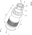
- the mating second connector attachment means 124 illustrated in Figure 2b will be described in more details also using Figures 3a and 3b .
- the mating second connector attachment means 124 is an elongated piece comprising different cross sections along its length.
- the mating secondconnector attachment means 124 comprises the connector attachment body 142 on its one end portion 124a and which is inserted into a locking element 144, itself connected to a portion carrying visual markings 146 on the other end portion 124b.
- the connector attachment body 142 of the mating second connector attachment means 124 comprises an inner hollow structure 148 into which is inserted a pushing element 150, a first spring 152, a second spring 154 and at least one movable connecting element 156.
- the mating second connector attachment means 124 comprises three movable connecting elements in the form of balls 156. The balls 156 are movable in a direction perpendicular to the central axis X of the inner hollow structure 148 as will be explained in detail further down.
- the balls 156 are located in through holes 158 situated on the lateral side parallel to the central axis X of the connector attachment body 142. The balls extend partially beyond the outside surface of the connector attachment body 142.
- the balls 156 are flush aligned with the wall of the hollow structure 148 and the pushing element 150 is placed in front of the balls 156, forced by the spring 152 against a stop element 153 on the hollow structure 148.
- the locking element 144 comprises an inner hollow structure with side walls 160 such that the connector attachment body 142 can be partially inserted into the inner hollow structure of the locking element 144 until the end portion 160a of the side walls 160 of the locking element 144 abuts against a base element 162 of the connector attachment body 142.
- the through holes 158 with the balls 156 are located inside the hollow structure of the locking element 144, adjacent to the base element 162.
- the balls 156 abut against a concave section 164 of the sidewall 160.
- the concave section 164 is pushed against the balls 156 by spring 154.
- the balls 156 are kept in place in the through holes 158, when the mating second electrical connector 106 is in it's unmount state.
- the balls 156 are pushed out of the hollow structure 148 by the pushing element 150.
- the concave section 164 is blocked by the balls 156 even under the force of the spring 154 and cannot move further in the mounting direction.
- the end portion 124a of the mating second connector attachment means 124 has a slit 166 that opens towards the end portion 124a and serves as a mechanical coding means.
- the slit 166 receives the protrusion 168 located on the connection axis 132 of the connector attachment means 114 and ensures a proper alignment.
- Figure 2b also illustrates the snap fit connection between the electrical connector 102 and the panel 104.
- Flexible hooks 200 engage with the backside 104b of the panel 104 and thereby mechanically connect the electrical connector 102 to the panel 104.
- Figure 2c illustrates a three-dimensional partial side cut view of the mating second electrical connector 106 being further mount onto the electrical connector 102.
- the connecting axis 132 of the connector attachment means 114 is now further inserted into the mating second connector attachment means 124.
- the end portion 132a of the connecting axis 132 of the connector attachment means 114 has pushed the pushing means 150 of the mating second connector attachment means 124 against the force of the first spring 152 such that the ball 156 is no positioned next to the end portion 132a of the connecting axis 132.
- the ball 156 no longer blocks the way for the locking element 144 and the second spring 154 pushes the locking element further in the mounting direction so that its flat section 172 blocks the ball 156 from moving out of the groove 170.
- the mechanical connection between the electrical connector 102 and its mating second electrical connector 106 is established and locked. This kind of connection is called a push-pull connection allowing the establishment of a locked connection, as well as its unlocking, without tools.
- the user can support the force of the second spring 154 and push the locking element 144 in the mounting direction to realize the mechanical connection and the locking.
- the visual marking 146 become visible confirming the user that the connection has been correctly realized.
- Figure 2e illustrates a three-dimensional view of the connector system according to the invention, the mating second electrical connector 106 being mount and locked onto the electrical connector 102.
- the mating second electrical connector 106 is mount and locked to the electrical connector 102 mount on a panel 104 without needing a tool and without loose parts. Due to the visual indication, a user always knows when the connection is correctly established. Thus a simple, yet reliable connection can be realized needing only one person and which is faster than the method of the prior art.
- the locking element 144 of the mating second connector attachment means 124 needs to be pushed in the direction opposite, as illustrated by the arrow to the direction of insertion, so that the concave section 164 is positioned next to the balls 156 which thereby become free to move out of the groove 170. Then the mating second electrical connector 106 can be pulled back.
Landscapes
- Details Of Connecting Devices For Male And Female Coupling (AREA)
Priority Applications (1)
| Application Number | Priority Date | Filing Date | Title |
|---|---|---|---|
| EP20315144.4A EP3893337A1 (fr) | 2020-04-09 | 2020-04-09 | Système de connecteur électrique |
Applications Claiming Priority (1)
| Application Number | Priority Date | Filing Date | Title |
|---|---|---|---|
| EP20315144.4A EP3893337A1 (fr) | 2020-04-09 | 2020-04-09 | Système de connecteur électrique |
Publications (1)
| Publication Number | Publication Date |
|---|---|
| EP3893337A1 true EP3893337A1 (fr) | 2021-10-13 |
Family
ID=70861405
Family Applications (1)
| Application Number | Title | Priority Date | Filing Date |
|---|---|---|---|
| EP20315144.4A Pending EP3893337A1 (fr) | 2020-04-09 | 2020-04-09 | Système de connecteur électrique |
Country Status (1)
| Country | Link |
|---|---|
| EP (1) | EP3893337A1 (fr) |
Cited By (3)
| Publication number | Priority date | Publication date | Assignee | Title |
|---|---|---|---|---|
| WO2023143664A1 (fr) * | 2022-01-26 | 2023-08-03 | HARTING Electronics GmbH | Connecteur enfichable, en particulier connecteur enfichable secondaire |
| EP4228107A1 (fr) * | 2022-02-11 | 2023-08-16 | Connecteurs Electriques Deutsch | Système d'installation rapide pour connecteurs électriques montés sur panneau |
| CN117039538A (zh) * | 2023-08-23 | 2023-11-10 | 康思立达(上海)汽车科技有限公司 | 一种新能源汽车的充电枪头锁紧装置 |
Citations (5)
| Publication number | Priority date | Publication date | Assignee | Title |
|---|---|---|---|---|
| JPH0660981U (ja) * | 1993-02-01 | 1994-08-23 | 矢崎総業株式会社 | パネル固定型コネクタ |
| EP0691712A1 (fr) * | 1994-07-04 | 1996-01-10 | Framatome Connectors International | Dispositif d'accouplement d'une paire de modules et son application à des connecteurs électriques complémentaires |
| DE102005034496A1 (de) * | 2005-07-20 | 2007-01-25 | Ims Connector Systems Gmbh | Steckverbinder und Gegenstecker |
| CN105428912A (zh) * | 2015-12-28 | 2016-03-23 | 苏州卓德电子有限公司 | 一种线束连接器 |
| US9608369B1 (en) * | 2016-05-09 | 2017-03-28 | Te Connectivity Corporation | Connector system with connector position assurance |
-
2020
- 2020-04-09 EP EP20315144.4A patent/EP3893337A1/fr active Pending
Patent Citations (5)
| Publication number | Priority date | Publication date | Assignee | Title |
|---|---|---|---|---|
| JPH0660981U (ja) * | 1993-02-01 | 1994-08-23 | 矢崎総業株式会社 | パネル固定型コネクタ |
| EP0691712A1 (fr) * | 1994-07-04 | 1996-01-10 | Framatome Connectors International | Dispositif d'accouplement d'une paire de modules et son application à des connecteurs électriques complémentaires |
| DE102005034496A1 (de) * | 2005-07-20 | 2007-01-25 | Ims Connector Systems Gmbh | Steckverbinder und Gegenstecker |
| CN105428912A (zh) * | 2015-12-28 | 2016-03-23 | 苏州卓德电子有限公司 | 一种线束连接器 |
| US9608369B1 (en) * | 2016-05-09 | 2017-03-28 | Te Connectivity Corporation | Connector system with connector position assurance |
Cited By (4)
| Publication number | Priority date | Publication date | Assignee | Title |
|---|---|---|---|---|
| WO2023143664A1 (fr) * | 2022-01-26 | 2023-08-03 | HARTING Electronics GmbH | Connecteur enfichable, en particulier connecteur enfichable secondaire |
| EP4228107A1 (fr) * | 2022-02-11 | 2023-08-16 | Connecteurs Electriques Deutsch | Système d'installation rapide pour connecteurs électriques montés sur panneau |
| CN117039538A (zh) * | 2023-08-23 | 2023-11-10 | 康思立达(上海)汽车科技有限公司 | 一种新能源汽车的充电枪头锁紧装置 |
| CN117039538B (zh) * | 2023-08-23 | 2024-05-10 | 康思立达(上海)汽车科技有限公司 | 一种新能源汽车的充电枪头锁紧装置 |
Similar Documents
| Publication | Publication Date | Title |
|---|---|---|
| EP3893337A1 (fr) | Système de connecteur électrique | |
| US6468100B1 (en) | BMA interconnect adapter | |
| US6409534B1 (en) | Coax cable connector assembly with latching housing | |
| US20160186792A1 (en) | Connection assembly with bayonet locking of the connection elements | |
| US5386486A (en) | Connecting system for field installation and cleaning | |
| US11600947B2 (en) | Electrical connector | |
| EP2311152A2 (fr) | Ensemble connecteur électrique pourvu d'un connecteur électrique sollicité par ressort | |
| BRPI0806235A2 (pt) | montagem de conector de três posições elétricas | |
| EP3291384B1 (fr) | Connecteur coudé | |
| US9490582B2 (en) | Insulation body of a plug-in connector | |
| US20170110824A1 (en) | Plug | |
| CN107925183B (zh) | 插拔连接器 | |
| JP6665117B2 (ja) | ケーブルの緊張緩和装置 | |
| US6450834B1 (en) | Panel mounting system for electrical connectors | |
| US7101192B1 (en) | Secondary locking device for a multi-pin connector | |
| JP2001035565A (ja) | 同軸ケーブル用電気コネクタ | |
| US6394856B1 (en) | Electrical connector with programmable keying | |
| US20230387627A1 (en) | Poke-in wire connector for power connector assembly | |
| US6805575B2 (en) | Guide system for contact plugs | |
| WO2022043823A1 (fr) | Connecteur électrique à déconnexion rapide activé par magnétique | |
| US5641298A (en) | Locking device for plug-socket electrical connector | |
| US5381308A (en) | Electrical component arranged for locking and electrically conecting in an opening of a panel fromexternally of the panel | |
| US10326239B2 (en) | Hydraulic tool for uncoupling a connection assembly, in particular with multi-contact connectors | |
| US9923303B2 (en) | Electrical connector with terminal centering system | |
| US6688922B2 (en) | Plug connector |
Legal Events
| Date | Code | Title | Description |
|---|---|---|---|
| PUAI | Public reference made under article 153(3) epc to a published international application that has entered the european phase |
Free format text: ORIGINAL CODE: 0009012 |
|
| STAA | Information on the status of an ep patent application or granted ep patent |
Free format text: STATUS: THE APPLICATION HAS BEEN PUBLISHED |
|
| AK | Designated contracting states |
Kind code of ref document: A1 Designated state(s): AL AT BE BG CH CY CZ DE DK EE ES FI FR GB GR HR HU IE IS IT LI LT LU LV MC MK MT NL NO PL PT RO RS SE SI SK SM TR |
|
| STAA | Information on the status of an ep patent application or granted ep patent |
Free format text: STATUS: REQUEST FOR EXAMINATION WAS MADE |
|
| 17P | Request for examination filed |
Effective date: 20220321 |
|
| RBV | Designated contracting states (corrected) |
Designated state(s): AL AT BE BG CH CY CZ DE DK EE ES FI FR GB GR HR HU IE IS IT LI LT LU LV MC MK MT NL NO PL PT RO RS SE SI SK SM TR |
|
| STAA | Information on the status of an ep patent application or granted ep patent |
Free format text: STATUS: EXAMINATION IS IN PROGRESS |
|
| 17Q | First examination report despatched |
Effective date: 20230620 |