EP3892986A1 - Foreign substance checking system - Google Patents
Foreign substance checking system Download PDFInfo
- Publication number
- EP3892986A1 EP3892986A1 EP19892210.6A EP19892210A EP3892986A1 EP 3892986 A1 EP3892986 A1 EP 3892986A1 EP 19892210 A EP19892210 A EP 19892210A EP 3892986 A1 EP3892986 A1 EP 3892986A1
- Authority
- EP
- European Patent Office
- Prior art keywords
- container
- foreign substance
- hammer
- powder
- checking system
- Prior art date
- Legal status (The legal status is an assumption and is not a legal conclusion. Google has not performed a legal analysis and makes no representation as to the accuracy of the status listed.)
- Pending
Links
Images

Classifications
-
- G—PHYSICS
- G01—MEASURING; TESTING
- G01N—INVESTIGATING OR ANALYSING MATERIALS BY DETERMINING THEIR CHEMICAL OR PHYSICAL PROPERTIES
- G01N21/00—Investigating or analysing materials by the use of optical means, i.e. using sub-millimetre waves, infrared, visible or ultraviolet light
- G01N21/84—Systems specially adapted for particular applications
- G01N21/88—Investigating the presence of flaws or contamination
- G01N21/90—Investigating the presence of flaws or contamination in a container or its contents
- G01N21/9009—Non-optical constructional details affecting optical inspection, e.g. cleaning mechanisms for optical parts, vibration reduction
-
- G—PHYSICS
- G01—MEASURING; TESTING
- G01N—INVESTIGATING OR ANALYSING MATERIALS BY DETERMINING THEIR CHEMICAL OR PHYSICAL PROPERTIES
- G01N21/00—Investigating or analysing materials by the use of optical means, i.e. using sub-millimetre waves, infrared, visible or ultraviolet light
- G01N21/84—Systems specially adapted for particular applications
- G01N21/88—Investigating the presence of flaws or contamination
- G01N21/90—Investigating the presence of flaws or contamination in a container or its contents
- G01N21/9018—Dirt detection in containers
- G01N21/9027—Dirt detection in containers in containers after filling
-
- G—PHYSICS
- G01—MEASURING; TESTING
- G01N—INVESTIGATING OR ANALYSING MATERIALS BY DETERMINING THEIR CHEMICAL OR PHYSICAL PROPERTIES
- G01N21/00—Investigating or analysing materials by the use of optical means, i.e. using sub-millimetre waves, infrared, visible or ultraviolet light
- G01N21/84—Systems specially adapted for particular applications
- G01N21/88—Investigating the presence of flaws or contamination
- G01N21/94—Investigating contamination, e.g. dust
-
- G—PHYSICS
- G06—COMPUTING OR CALCULATING; COUNTING
- G06T—IMAGE DATA PROCESSING OR GENERATION, IN GENERAL
- G06T7/00—Image analysis
- G06T7/0002—Inspection of images, e.g. flaw detection
- G06T7/0004—Industrial image inspection
-
- G—PHYSICS
- G01—MEASURING; TESTING
- G01N—INVESTIGATING OR ANALYSING MATERIALS BY DETERMINING THEIR CHEMICAL OR PHYSICAL PROPERTIES
- G01N21/00—Investigating or analysing materials by the use of optical means, i.e. using sub-millimetre waves, infrared, visible or ultraviolet light
- G01N21/84—Systems specially adapted for particular applications
- G01N21/88—Investigating the presence of flaws or contamination
- G01N21/90—Investigating the presence of flaws or contamination in a container or its contents
- G01N21/9036—Investigating the presence of flaws or contamination in a container or its contents using arrays of emitters or receivers
-
- G—PHYSICS
- G01—MEASURING; TESTING
- G01N—INVESTIGATING OR ANALYSING MATERIALS BY DETERMINING THEIR CHEMICAL OR PHYSICAL PROPERTIES
- G01N33/00—Investigating or analysing materials by specific methods not covered by groups G01N1/00 - G01N31/00
- G01N33/0078—Testing material properties on manufactured objects
- G01N33/0081—Containers; Packages; Bottles
Definitions
- a weight of the powder sealed in the container is within a range of 0.20 to 10 grams.
- the hammer comprises an elastic body.
- Examples of the pharmaceutical agents include ampicillin, bacampicillin, amoxicillin, pivmecillinam, amoxicillin, sultamicillin, piperacillin, aspoxicillin, benzylpenicillin, cloxacillin, oxacillin, carbenicillin, cefaclor, cefroxadine, cefadroxil, cefixime, cefteram pivoxil, cefuroxime axetil, cefpodoxime proxetil, cefotiam hexetil, cefdinir, ceftibuten, cefditoren pivoxil, cefcapene pivoxil, cefazolin, cefozopran, cefmetazole, cefotiam, cefsulodin, cefoperazone, cefotaxime, cefmenoxime, ceftriaxone, ceftazidime, cefodizime, cefpirome, cefepime
- the container 20 has a rectangular bag shape in a plan view, capable of containing the powder 21 therein.
- the container 20 is formed by thermally fusion-bonding laminate sheets obtained by laminating a plurality of synthetic resin sheets, for example.
- a transparent region 22 is formed in one surface of the bag-like container 20, a transparent region 22 is formed.
- the transparent region 22 is formed of a transparent resin sheet. The powder 21 contained in the internal space is visible through the transparent region 22.
- the transparent region 22 is formed on an outer surface of the container 20 over an entire space in which the powder 21 can be contained. Therefore, the transparent region 22 is a work area with which a hammer 32 can collide.
- the work area is preferably within a range of 4000 mm 2 to 7000 mm 2 , and more preferably within a range of 4800 mm 2 to 6000 mm 2 .
- a crack is likely to be generated, because an impact caused by the collision of the hammer 32 becomes local.
- the work area is larger than the above ranges, the impact caused by the collision of the hammer 32 is dispersed, and the foreign substance mixed in the powder 21 is less likely to appear.
- the collision area can be adjusted by the distance between the rotating shaft 31 and the container 20, the projecting length of the convex portion 34, and a projecting width of the convex portion 34. Since the portion 36 of the outer surface 35 of the hammer 32 has a flat surface, the crack is less likely to be generated in the powder 21, and the foreign substance that appears from the powder 21 is less likely to disappear.
- Example 1 The number of the hammers 32 was seven, and an outer surface of a collision portion of each hammer 32 had a flat surface.
- the collision area of each hammer 32 was within a range of 15 mm 2 to 25 mm 2 .
- a total collision area of the seven hammers 32 was within a range of 105 mm 2 to 175 mm 2 .
- the work area of the container 20 was set to 6000 mm 2 . Therefore, a ratio of the collision area of the hammers 32 to the work area was about 1.75% to 2.92%.
- Comparative Example 1 The number of the hammers 32 was seven, and the collision portion of each hammer 32 was a convex portion which was a corner of a triangular prism. The collision area of each hammer 32 was 5 mm 2 . The total collision area of the seven hammers 32 was 35 mm 2 . Further, the work area of the container 20 was set to 6000 mm 2 . Therefore, the ratio of the collision area of the hammers 32 to the work area was about 0.58%.
Landscapes
- Physics & Mathematics (AREA)
- General Physics & Mathematics (AREA)
- General Health & Medical Sciences (AREA)
- Chemical & Material Sciences (AREA)
- Analytical Chemistry (AREA)
- Biochemistry (AREA)
- Life Sciences & Earth Sciences (AREA)
- Health & Medical Sciences (AREA)
- Immunology (AREA)
- Pathology (AREA)
- Engineering & Computer Science (AREA)
- Quality & Reliability (AREA)
- Computer Vision & Pattern Recognition (AREA)
- Theoretical Computer Science (AREA)
- Investigating Materials By The Use Of Optical Means Adapted For Particular Applications (AREA)
Abstract
Description
- The present invention relates to a foreign substance checking system that checks whether a foreign substance is present inside a bag-like container in which a powder is sealed and which has a region where the powder is visible from the outside.
- Conventionally, as a form in which powdered pharmaceuticals, such as powdered medicines, fine granules, granules, and injections are packaged, a bag-like container having a region where a powder is visible from the outside is mentioned. As a checking for the presence of a foreign substance in the powder contained in the container, a visual checking and a checking performed by analyzing optically obtained image data are known (Patent Document 1). A foreign substance detecting device described in
Patent Document 1 optically detects a foreign substance in a powder when a vibration is applied to a bag-like body containing the powder. - Patent Document 1:
Japanese Patent Application Laid-Open No. 2001-4549 - However, when the vibration is applied to the bag-like body, a crack is sometimes generated in a powder mass. Since this crack appears as a shadow in an image, the shadow is sometimes determined as the foreign substance when the image is analyzed. As a result, a product, which is actually a good product in which no foreign substance is present, may be determined to be a defective product in which the foreign substance is present.
- The present invention has been made in view of the above-described circumstances. An object of the present invention is to provide a means that is less likely to misidentify a crack as a foreign substance during an image checking in which a vibration is applied to a powder contained in a bag-like container.
- (1) The present invention relates to a foreign substance checking system that checks whether a foreign substance is present inside a bag-like container in which a powder is sealed and which has a region where the powder is visible from an outside. The foreign substance checking system includes a vibration device configured to apply a vibration to the container, a photography device configured to optically photograph an inside of the container through the region from the outside, and a determination device configured to determine whether the foreign substance is present inside the container based on an image of the container photographed by the photography device. The vibration device includes a rotating shaft and a hammer rotating in conjunction with the rotating shaft and colliding with the container. A region of an outer surface of the hammer to collide with the container has a flat surface.
- By making the hammer collide with the container to apply a vibration to the container, the foreign substance buried inside the powder can be made to appear so that the foreign substance can be photographed. By making the hammer collide with the container to apply a vibration to the container, the foreign substance buried inside the powder can be made to appear so that the foreign substance can be photographed. Since the region of the outer surface of the hammer to collide with the container has the flat surface, a crack is less likely to be generated in the powder and the foreign substance that appears is less likely to disappear. With this, based on the obtained image, an accuracy of determining whether the foreign substance other than the powder is present inside the container is improved.
- (2) Preferably, a ratio of a collision area of an outer surface, on the hammer, which collides with the outer surface of the container to a work area corresponding to a space in which the powder can be sealed, on an outer surface of the container on which the hammer abuts is within a range of 1 to 4%.
- Since the collision area with respect to the work area is within the range of 1 to 4%, the crack is less likely to be generated in the powder and the foreign substance that appears is less likely to disappear. With this, based on the obtained image, the accuracy of determining whether the foreign substance other than the powder is present inside the container is improved.
- (3) Preferably, the vibration device includes a plurality of the hammers in conjunction with one rotating shaft, and the collision area is a sum of an area of an outer surface, on each of the hammers, the region colliding with the outer surface of the container.
- (4) Preferably, the vibration device includes a plurality of sets of the plurality of the hammers in conjunction with one rotating shaft.
- (5) Preferably, an area of an outer surface of one hammer to collide with the outer surface of the container is within a range of 15 to 25 square millimeters.
- (6) Preferably, the work area is within a range of 4000 to 7000 square millimeters.
- (7) Preferably, a weight of the powder sealed in the container is within a range of 0.20 to 10 grams.
- (8) Preferably, the hammer comprises an elastic body.
- (9) Preferably, an outer surface of the container with which the outer surface of the hammer collides has a flat surface.
- According to the present invention, it is less likely to misidentify a crack as the foreign substance during an image checking in which the vibration is applied to the powder contained in the bag-like container.
-
-
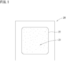
FIG. 1 is a plan view of acontainer 20. -
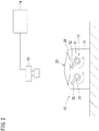
FIG. 2 is a schematic view of a foreignsubstance checking system 10. -
FIG. 3 is an external perspective view of ahammer 32. - Hereinafter, an embodiment of the present invention will be described with reference to the drawings as appropriate. It is a matter of course that the embodiment described below is merely an example of the present invention, and the embodiment of the present invention can be appropriately modified without changing the gist of the present invention. In the following description, a vertical direction 5 is defined based on the top and the bottom, a forward and backward direction 6 (direction perpendicular to the sheet surface of
FIG. 2 ) is defined in a direction perpendicular to the vertical direction 5, and a left and right direction 7 is defined in a direction perpendicular to each of the vertical direction 5 and the forward and backward direction 6. - As illustrated in
FIG. 1 , an object to be checked by a foreignsubstance checking system 10 described later is acontainer 20 in which apowder 21 is contained. Thepowder 21 is a pharmaceutical agent, such as powdered medicines, fine granules, granules, and injections. The pharmaceutical agents are not particularly limited, and, for example, cell wall synthesis inhibitor antibiotics, cell membrane inhibitor antibiotics, nucleic acid synthesis inhibitor antibiotics, protein synthesis inhibitor antibiotics, folic acid metabolic pathway inhibitor antibiotics, β-lactamase inhibitors, sulfa drugs, and anti-infective drugs are preferable. Examples of the pharmaceutical agents include ampicillin, bacampicillin, amoxicillin, pivmecillinam, amoxicillin, sultamicillin, piperacillin, aspoxicillin, benzylpenicillin, cloxacillin, oxacillin, carbenicillin, cefaclor, cefroxadine, cefadroxil, cefixime, cefteram pivoxil, cefuroxime axetil, cefpodoxime proxetil, cefotiam hexetil, cefdinir, ceftibuten, cefditoren pivoxil, cefcapene pivoxil, cefazolin, cefozopran, cefmetazole, cefotiam, cefsulodin, cefoperazone, cefotaxime, cefmenoxime, ceftriaxone, ceftazidime, cefodizime, cefpirome, cefepime, faropenem, imipenem, panipenem, meropenem, biapenem, doripenem, aztreonam, vancomycin, teicoplanin, fosmicin, polymixin B sulfate, colistin sulfate, gramicidin S, amphotericin B, levofloxacin, ofloxacin, norfloxacin, enoxacin, ciprofloxacin, lomefloxacin, tosufloxacin, sparfloxacin, gatifloxacin, prulifloxacin, moxifloxacin, pazufloxacin, rifampicin, dibekacin, tobramycin, amikacin, isepamicin, micronomicin, streptomycin, kanamycin, gentamicin, erythromycin, rokitamycin, josamycin, roxithromycin, clarithromycin, azithromycin, telithromycin, doxycycline, minocycline, chloramphenicol, lincomycin, clindamycin, trimethoprim, clavulanic acid, sulbactam, tazobactam, sulfamethoxazole, salazopyrin, isoniazid, rifampicin, pyrazinamide, ethambutol, griseofulvin, amphotericin B, 5-fluorocytosine, fluconazole, miconazole, itraconazole, aciclovir, ganciclovir, foscavir, idoxuridine, amantadine, interferon γ, ribavirin, lamivudine, metronidazole, tinidazole, fluconazole, mebendazole, pyrantel pamoate, diethylcarbamazine, praziquantel, albendazole, ivermectin, quinupristin, dalfopristin, linezolid, spectinomycin, netilmicin, sisomycin, lincosamin, ramoplanin, telithromycin, nystatin, fusidic acid, chlorhexidine, polyhexanide, and the like. - As the properties of the
powder 21 that is easily cracked by the application of a vibration, the angle of repose, the particle size, and the filling amount can be mentioned, for example. The angle of repose of thepowder 21 is relatively low and specifically less than 46° and preferably less than 45°. The particle size of thepowder 21 is large, and specifically the average particle size is 60 µm or more and preferably 64 µm or more. - The filling amount of the
powder 21 contained in thecontainer 20 is preferably within a range of 0.2 g to 10 g, and more preferably within a range of 0.2 g to 5 g. When the filling amount of thepowder 21 contained in thecontainer 20 is less than each of the above ranges, a crack is less likely to be generated in thepowder 21. Meanwhile, when the filling amount of thepowder 21 contained in thecontainer 20 is larger than each of the above ranges, a foreign substance mixed in thepowder 21 is less likely to appear. - The
container 20 has a rectangular bag shape in a plan view, capable of containing thepowder 21 therein. Thecontainer 20 is formed by thermally fusion-bonding laminate sheets obtained by laminating a plurality of synthetic resin sheets, for example. In one surface of the bag-like container 20, atransparent region 22 is formed. Thetransparent region 22 is formed of a transparent resin sheet. Thepowder 21 contained in the internal space is visible through thetransparent region 22. - In the present embodiment, the
transparent region 22 is formed on an outer surface of thecontainer 20 over an entire space in which thepowder 21 can be contained. Therefore, thetransparent region 22 is a work area with which ahammer 32 can collide. The work area is preferably within a range of 4000 mm2 to 7000 mm2, and more preferably within a range of 4800 mm2 to 6000 mm2. When the work area is smaller than the above ranges, a crack is likely to be generated, because an impact caused by the collision of thehammer 32 becomes local. Meanwhile, when the work area is larger than the above ranges, the impact caused by the collision of thehammer 32 is dispersed, and the foreign substance mixed in thepowder 21 is less likely to appear. - As illustrated in
FIG. 2 , the foreignsubstance checking system 10 includes asupport base 11, avibration device 12, aphotography device 13, and adetermination device 14. - The
support base 11 is a flat base on which thecontainer 20 can be mounted on its upper surface.Hammers 32 of thevibration device 12 are located in a cavity at the center of theupper surface 30 of thesupport base 11. Theupper surface 30 of thesupport base 11 supports a peripheral portion of thecontainer 20. Thecontainer 20 is supported by thesupport base 11 so that thetransparent region 22 faces upward. An outer surface of thecontainer 20 exposed downward from the cavity of theupper surface 30 of thesupport base 11 forms a flat surface which is substantially along a horizontal direction. An area of the outer surface of thecontainer 20 exposed downward from the cavity of theupper surface 30 of thesupport base 11 is the work area. Although not illustrated, thesupport base 11 may be provided with a clip for fixing thecontainer 20 or a suction port for sucking and fixing thecontainer 20. Further, to make thesupport base 11 support thecontainers 20 sequentially, a transport device may be provided. - Below the
upper surface 30 of thesupport base 11, thevibration device 12 is located. Thevibration device 12 has rotatingshafts 31 and thehammers 32 rotating in conjunction with therotating shafts 31 and colliding with thecontainer 20. In this embodiment, two rotatingshafts 31 are located apart from each other in the left and right direction 7 along the forward and backward direction 6 (direction perpendicular to the sheet surface ofFIG. 2 ). Each of the tworotating shafts 31 rotates by the transmission of rotation from a motor (not illustrated). - Two or more of the
hammers 32 are fixed apart from each other in the forward and backward direction 6 with respect to one rotatingshaft 31. Thehammers 32 are formed of an elastic material, such as chlorinated butyl rubber, butyl rubber, and silicone rubber. Although in this embodiment, the plurality ofhammers 32 fixed to one rotatingshaft 31 project in the same direction from the rotatingshaft 31, the directions in which the plurality ofhammers 32 project from the rotatingshaft 31 may be different. - Since a shape of each
hammer 32 is the same, a shape of onehammer 32 will be described. As illustrated inFIG. 3 , thehammer 32 has anannular portion 33 that is externally fitted to therotating shaft 31, and aconvex portion 34 that projects from theannular portion 33 in a radial direction of therotating shaft 31. Theannular portion 33 has a cylindrical shape. The rotatingshaft 31 is inserted into a hollow of theannular portion 33, and theannular portion 33 rotates integrally with the rotatingshaft 31. - The
convex portion 34 has a quadrangular prism shape. Among outer surfaces of theconvex portion 34,outer surfaces 35 along the rotatingshaft 31 have a flat surface. One of the twoouter surfaces 35 is a surface that can collide with the outer surface of thecontainer 20. Whichouter surface 35 of the twoouter surfaces 35 collides with the outer surface of thecontainer 20 depends on a rotation direction of therotating shaft 31. Further, a portion of theouter surface 35 of theconvex portion 34 collides with the outer surface of thecontainer 20. The portion of theouter surface 35 that can collide with the outer surface of thecontainer 20 depends on a distance between therotating shaft 31 and the outer surface of thecontainer 20 and a projecting length of theconvex portion 34. It is preferable that a portion of theouter surface 35 including a tip in a projecting direction collide with the outer surface of thecontainer 20. That is, theouter surface 35 of thehammer 32 and the outer surface of thecontainer 20 are in a surface contact in which flat surfaces are in contact with each other. InFIG. 3 , the portion of theouter surface 35 that can collide with the outer surface of thecontainer 20 is hatched and is indicated by areference numeral 36. An area of the portion 36 (an example of a region) is a collision area. In the present embodiment, since a plurality ofhammers 32 are provided, the collision area is a total value of an area of theportion 36 of theouter surface 35 of eachhammer 32. The collision area can be adjusted by the distance between therotating shaft 31 and thecontainer 20, the projecting length of theconvex portion 34, and a projecting width of theconvex portion 34. Since theportion 36 of theouter surface 35 of thehammer 32 has a flat surface, the crack is less likely to be generated in thepowder 21, and the foreign substance that appears from thepowder 21 is less likely to disappear. - The area of the
portion 36 of theouter surface 35 with respect to the work area, that is, a ratio of the collision area is preferably 0.8% or more, more preferably within a range of 1% to 4%, particularly preferably within a range of 1.1% to 3.7%, and further preferably within a range of 1.7% to 3.05%. When the ratio of the collision area to the work area is smaller than the above ranges, an area where the impact of thehammer 32 colliding with thecontainer 20 is transmitted becomes small, and the crack is less likely to be generated in thepowder 21. When the ratio of the collision area to the work area is larger than the above ranges, the impact caused by the collision of thehammer 32 is dispersed, and the foreign substance mixed in thepowder 21 is less likely to appear. - In the
convex portion 34, a length L1 along an axial direction of therotating shaft 31 is longer than a length L2 along a tangential direction with respect to a circumferential direction of the rotating shaft 31 (L1 > L2) . In a state where thehammer 32 projects substantially upward from the rotatingshaft 31, thehammer 32 can abut on thecontainer 20 supported by theupper surface 30 of thesupport base 11. The rotation of rotatingshaft 31 alternately generates timings when thehammers 32 abut on thecontainer 20 and timings when thehammers 32 are separated from thecontainer 20, and as a result, thehammers 32 strike thecontainer 20. By the striking of thehammers 32 described above, a vibration is applied to thecontainer 20. - By making the
hammers 32 collide with thecontainer 20 to apply a vibration to thecontainer 20, the foreign substance buried inside thepowder 21 can be made to appear so that the foreign substance can be photographed. Since the collision area with respect to the work area is within the range of 1 to 4%, the crack is less likely to be generated in thepowder 21 and the foreign substance that appears is less likely to disappear. With this, based on the obtained image, an accuracy of determining whether the foreign substance other than thepowder 21 is present inside thecontainer 20 is improved. - The
photography device 13 is located above theupper surface 30 of thesupport base 11. In other words, thephotography device 13 is located on the opposite side to thevibration device 12 in the vertical direction 5, with thecontainer 20 supported by theupper surface 30 of thesupport base 11 interposed between thevibration device 12 and thephotography device 13. Thephotography device 13 optically photographs the inside of thecontainer 20 through thetransparent region 22 from the outside of thecontainer 20, and is a monochrome CCD camera, for example. Thephotography device 13 outputs the photographed image as image data. Thephotography device 13photographs 30 images per second, for example, and outputs the images as the image data. - The
determination device 14 can receive the image data output from thephotography device 13. Thedetermination device 14 determines whether a foreign substance is present inside thecontainer 20 based on the images of thecontainer 20 photographed by thephotography device 13, i.e., the image data. Specifically, the obtained one piece of image data is vertically and horizontally divided into a predetermined number of regions, and the color density of each region is identified in a plurality of stages. When thepowder 21 is white, the foreign substance is recognized as black. Then, it is determined whether the foreign substance is present from a peak value (color density of foreign substance), an intensity volume value (height × width × color density of foreign substance), and an intensity area value (height × width of foreign substance) in the image data. For example, when all of the peak value, the intensity volume value, and the intensity area value are within predetermined conditions, e.g., when there is a predetermined continuous range where each value is equal to or higher than a threshold value, thedetermination device 14 determines that the foreign substance is present in thecontainer 20. - Hereinafter, an example of a foreign substance checking method using the foreign
substance checking system 10 will be described. - Example 1: The number of the
hammers 32 was seven, and an outer surface of a collision portion of eachhammer 32 had a flat surface. The collision area of eachhammer 32 was within a range of 15 mm2 to 25 mm2. A total collision area of the seven hammers 32 was within a range of 105 mm2 to 175 mm2. Further, the work area of thecontainer 20 was set to 6000 mm2. Therefore, a ratio of the collision area of thehammers 32 to the work area was about 1.75% to 2.92%. - Comparative Example 1: The number of the
hammers 32 was seven, and the collision portion of eachhammer 32 was a convex portion which was a corner of a triangular prism. The collision area of eachhammer 32 was 5 mm2. The total collision area of the seven hammers 32 was 35 mm2. Further, the work area of thecontainer 20 was set to 6000 mm2. Therefore, the ratio of the collision area of thehammers 32 to the work area was about 0.58%. - Good product misdetection rate: A test was performed on 88 bags of the
container 20 using the foreignsubstance checking system 10 according to Example 1, and a percentage was obtained by counting the number ofcontainers 20 with respect to which the foreign substance was determined to be mixed. Further, a test was performed on 10 bags of the container using the foreignsubstance checking system 10 according to Comparative Example 1, and a percentage was obtained by counting the number of containers with respect to which the foreign substance was determined to be mixed. The results are shown in Table 1. - Foreign substance detection rate: One of a carbon powder having an outer diameter of about 300 µm, a stainless powder having an outer diameter of about 1000 µm, and a black polypropylene powder having an outer diameter of about 3000 µm was mixed in each
container 20, a test was performed on 20 bags of thecontainer 20 using the foreignsubstance checking system 10 according to Example 1, and a percentage was obtained by counting the number ofcontainers 20 with respect to which the foreign substance was determined to be mixed. The results are shown in Table 1.Table 1: Good product misdetection rate and foreign substance detection rate Good product misdetection rate Carbon powder Stainless powder Polypropylene powder Example 1 0 % 100 % 100 % 100 % Comparative Example 1 30 % - - - - As illustrated in Table 1, the good product misdetection rate was 0% in Example 1. In contrast, the good product misdetection rate was 30% in Comparative Example 1. Further, in Example 1, a foreign substance contamination was detected in all of the
containers 20 in which the carbon powder, the stainless powder, or the polypropylene powder was mixed. -
- 10
- foreign substance checking system
- 12
- vibration device
- 13
- photography device
- 14
- determination device
- 20
- container
- 21
- powder
- 22
- transparent region (work area)
- 31
- rotating shaft
- 32
- hammer
- 35
- outer surface
- 36
- portion (collision area)
Claims (9)
- A foreign substance checking system that checks whether a foreign substance is present inside a bag-like container in which a powder is sealed and which has a region where the powder is visible from an outside,
the foreign substance checking system comprising:a vibration device configured to apply a vibration to the container;a photography device configured to optically photograph an inside of the container through the region from the outside; anda determination device configured to determine whether the foreign substance is present inside the container based on an image of the container photographed by the photography device, whereinthe vibration device includes a rotating shaft and a hammer rotating in conjunction with the rotating shaft and colliding with the container, anda region of an outer surface of the hammer to collide with the container has a flat surface. - The foreign substance checking system according to Claim 1, wherein
a ratio of a collision area, which is an area of the region on the outer surface of the hammer, to a work area corresponding to a space in which the powder can be sealed, on an outer surface of the container on which the hammer abuts is within a range of 1 to 4%. - The foreign substance checking system according to Claim 2, wherein
the vibration device includes a plurality of the hammers in conjunction with one rotating shaft, and the collision area is a sum of an area of a region of an outer surface, on each of the hammers, the region colliding with the outer surface of the container. - The foreign substance checking system according to Claim 3, wherein
the vibration device includes a plurality of sets of the plurality of the hammers in conjunction with one rotating shaft. - The foreign substance checking system according to any one of Claims 2 to 4, wherein
an area of an outer surface of one hammer to collide with the outer surface of the container is within a range of 15 to 25 square millimeters. - The foreign substance checking system according to any one of Claims 2 to 5, wherein
the work area is within a range of 4000 to 7000 square millimeters. - The foreign substance checking system according to any one of Claims 1 to 6, wherein
a weight of the powder sealed in the container is within a range of 0.20 to 10 grams. - The foreign substance checking system according to any one of Claims 1 to 7, wherein
the hammer comprises an elastic body. - The foreign substance checking system according to any one of Claims 1 to 8, wherein
an outer surface of the container with which the region of the outer surface of the hammer collides has a flat surface.
Applications Claiming Priority (2)
| Application Number | Priority Date | Filing Date | Title |
|---|---|---|---|
| JP2018228259 | 2018-12-05 | ||
| PCT/JP2019/042321 WO2020116053A1 (en) | 2018-12-05 | 2019-10-29 | Foreign substance checking system |
Publications (2)
| Publication Number | Publication Date |
|---|---|
| EP3892986A1 true EP3892986A1 (en) | 2021-10-13 |
| EP3892986A4 EP3892986A4 (en) | 2022-08-10 |
Family
ID=70974608
Family Applications (1)
| Application Number | Title | Priority Date | Filing Date |
|---|---|---|---|
| EP19892210.6A Pending EP3892986A4 (en) | 2018-12-05 | 2019-10-29 | FOREIGN SUBSTANCE VERIFICATION SYSTEM |
Country Status (4)
| Country | Link |
|---|---|
| US (1) | US11761902B2 (en) |
| EP (1) | EP3892986A4 (en) |
| JP (1) | JP7318664B2 (en) |
| WO (1) | WO2020116053A1 (en) |
Family Cites Families (12)
| Publication number | Priority date | Publication date | Assignee | Title |
|---|---|---|---|---|
| JPH01155238A (en) * | 1987-12-14 | 1989-06-19 | Takeda Chem Ind Ltd | Method for inspecting foreign matter in powder allowed to fill transparent container |
| JPH0752161B2 (en) * | 1988-12-02 | 1995-06-05 | 富士電機株式会社 | Inspection device for foreign matter in powder in transparent container |
| JP2719410B2 (en) * | 1989-07-19 | 1998-02-25 | 日鉄鉱業株式会社 | Automatic inspection equipment for powder sealed transparent containers |
| JP2000298103A (en) * | 1999-04-15 | 2000-10-24 | Nittetsu Mining Co Ltd | Foreign particle inspection device for powder in transparent containers |
| JP4279945B2 (en) | 1999-06-24 | 2009-06-17 | 第一三共株式会社 | Foreign matter detection device in powder |
| US6854348B2 (en) | 2001-08-30 | 2005-02-15 | Shin-Etsu Chemical Co., Ltd. | Method for counting foreign matter particles in vinyl chloride-based resin powder and apparatus system therefor |
| JP3722437B2 (en) * | 2001-08-30 | 2005-11-30 | 信越化学工業株式会社 | Automatic measurement system for foreign matter in vinyl chloride resin powder |
| US20090294469A1 (en) * | 2008-05-30 | 2009-12-03 | Ecolab Inc. | Mass-Based Powder Dispensing |
| JP5307459B2 (en) | 2008-06-30 | 2013-10-02 | 株式会社 デクシス | Foreign matter inspection method and foreign matter inspection device in powder in transparent container |
| JP2014006186A (en) * | 2012-06-26 | 2014-01-16 | Fuji Electric Co Ltd | Foreign matter inspection device |
| US20140250835A1 (en) * | 2013-03-05 | 2014-09-11 | Howmedica Osteonics Corp. | Process for removing contaminants from polymeric powders |
| JP7294349B2 (en) | 2018-10-31 | 2023-06-20 | ニプロ株式会社 | Foreign matter inspection system and foreign matter inspection method |
-
2019
- 2019-10-29 JP JP2020559789A patent/JP7318664B2/en active Active
- 2019-10-29 WO PCT/JP2019/042321 patent/WO2020116053A1/en not_active Ceased
- 2019-10-29 US US17/298,989 patent/US11761902B2/en active Active
- 2019-10-29 EP EP19892210.6A patent/EP3892986A4/en active Pending
Also Published As
| Publication number | Publication date |
|---|---|
| JPWO2020116053A1 (en) | 2021-10-14 |
| WO2020116053A1 (en) | 2020-06-11 |
| US20220050059A1 (en) | 2022-02-17 |
| JP7318664B2 (en) | 2023-08-01 |
| EP3892986A4 (en) | 2022-08-10 |
| US11761902B2 (en) | 2023-09-19 |
Similar Documents
| Publication | Publication Date | Title |
|---|---|---|
| JP2024026817A (en) | Manufacturing method for powder enclosure | |
| US11071782B2 (en) | Method of filling a container with no headspace | |
| US11971363B2 (en) | Foreign matter inspection system and foreign matter inspection method | |
| CN102573967B (en) | Negatively biased sealed nebulizer systems and methods | |
| AU2002342479A1 (en) | System for filling and assembling pharmaceutical delivery devices | |
| ZA200801361B (en) | Solid pharmaceutical dosage form | |
| US20120018338A1 (en) | Method for avoiding glass fogging | |
| WO2014121342A1 (en) | Methods of treating topical microbial infections | |
| KR20090042995A (en) | Antibiotic composition consisting of β-lactam antibiotics and buffers | |
| CA3054947A1 (en) | Treatment of a disease of the gastrointestinal tract with live biotherapeutics | |
| WO2012102216A1 (en) | Medical device containing a cake composition comprising aripiprazole as an active ingredient, and a cake composition comprising aripiprazole as an active ingredient | |
| CA2597812A1 (en) | Parenteral combination therapy for infective conditions with drug resistant bacterium | |
| US11761902B2 (en) | Foreign substance checking system | |
| US20180043020A1 (en) | Method of reducing immunogenicity of drug products | |
| WO2019064263A1 (en) | Novel formulations which stabilize low dose antibody compositions | |
| EP3618813B1 (en) | Improved extended release highly loaded drug compositions | |
| EP4374848A1 (en) | Antibiotic pharmaceutical composition capable of subcutaneous administration | |
| WO2016157061A1 (en) | Aseptic wet milling process for paliperidone palmitate | |
| CN103025318A (en) | Suspension and cake composition containing carbostyryl derivative and silicone oil and/or silicone oil derivative | |
| EP4005555B1 (en) | Methods for ensuring resuspension of paliperidone palmitate formulations | |
| US20140018323A1 (en) | Sustained-release injectable formulation | |
| Dakdouki et al. | Azithromycin-induced rash in infectious mononucleosis | |
| WO2018002956A1 (en) | Stable injectable solution of pemetrexed | |
| ES2759004T3 (en) | Oral administration of unstable or poorly absorbed medications | |
| CN116782865A (en) | Atomic layer deposition coated pharmaceutical packaging and improved syringes and vials e.g. for lyophilized/cold chain pharmaceuticals/vaccines |
Legal Events
| Date | Code | Title | Description |
|---|---|---|---|
| STAA | Information on the status of an ep patent application or granted ep patent |
Free format text: STATUS: THE INTERNATIONAL PUBLICATION HAS BEEN MADE |
|
| PUAI | Public reference made under article 153(3) epc to a published international application that has entered the european phase |
Free format text: ORIGINAL CODE: 0009012 |
|
| STAA | Information on the status of an ep patent application or granted ep patent |
Free format text: STATUS: REQUEST FOR EXAMINATION WAS MADE |
|
| 17P | Request for examination filed |
Effective date: 20210624 |
|
| AK | Designated contracting states |
Kind code of ref document: A1 Designated state(s): AL AT BE BG CH CY CZ DE DK EE ES FI FR GB GR HR HU IE IS IT LI LT LU LV MC MK MT NL NO PL PT RO RS SE SI SK SM TR |
|
| DAV | Request for validation of the european patent (deleted) | ||
| DAX | Request for extension of the european patent (deleted) | ||
| A4 | Supplementary search report drawn up and despatched |
Effective date: 20220708 |
|
| RIC1 | Information provided on ipc code assigned before grant |
Ipc: G01N 21/90 20060101AFI20220704BHEP |
|
| STAA | Information on the status of an ep patent application or granted ep patent |
Free format text: STATUS: EXAMINATION IS IN PROGRESS |
|
| 17Q | First examination report despatched |
Effective date: 20250221 |