EP3892824A1 - Pin attachment for cmc components - Google Patents
Pin attachment for cmc components Download PDFInfo
- Publication number
- EP3892824A1 EP3892824A1 EP21161855.8A EP21161855A EP3892824A1 EP 3892824 A1 EP3892824 A1 EP 3892824A1 EP 21161855 A EP21161855 A EP 21161855A EP 3892824 A1 EP3892824 A1 EP 3892824A1
- Authority
- EP
- European Patent Office
- Prior art keywords
- pin
- hole
- component
- radius
- component assembly
- Prior art date
- Legal status (The legal status is an assumption and is not a legal conclusion. Google has not performed a legal analysis and makes no representation as to the accuracy of the status listed.)
- Granted
Links
Images




Classifications
-
- F—MECHANICAL ENGINEERING; LIGHTING; HEATING; WEAPONS; BLASTING
- F01—MACHINES OR ENGINES IN GENERAL; ENGINE PLANTS IN GENERAL; STEAM ENGINES
- F01D—NON-POSITIVE DISPLACEMENT MACHINES OR ENGINES, e.g. STEAM TURBINES
- F01D25/00—Component parts, details, or accessories, not provided for in, or of interest apart from, other groups
- F01D25/24—Casings; Casing parts, e.g. diaphragms, casing fastenings
- F01D25/246—Fastening of diaphragms or stator-rings
-
- F—MECHANICAL ENGINEERING; LIGHTING; HEATING; WEAPONS; BLASTING
- F01—MACHINES OR ENGINES IN GENERAL; ENGINE PLANTS IN GENERAL; STEAM ENGINES
- F01D—NON-POSITIVE DISPLACEMENT MACHINES OR ENGINES, e.g. STEAM TURBINES
- F01D11/00—Preventing or minimising internal leakage of working-fluid, e.g. between stages
- F01D11/08—Preventing or minimising internal leakage of working-fluid, e.g. between stages for sealing space between rotor blade tips and stator
-
- F—MECHANICAL ENGINEERING; LIGHTING; HEATING; WEAPONS; BLASTING
- F16—ENGINEERING ELEMENTS AND UNITS; GENERAL MEASURES FOR PRODUCING AND MAINTAINING EFFECTIVE FUNCTIONING OF MACHINES OR INSTALLATIONS; THERMAL INSULATION IN GENERAL
- F16B—DEVICES FOR FASTENING OR SECURING CONSTRUCTIONAL ELEMENTS OR MACHINE PARTS TOGETHER, e.g. NAILS, BOLTS, CIRCLIPS, CLAMPS, CLIPS OR WEDGES; JOINTS OR JOINTING
- F16B19/00—Bolts without screw-thread; Pins, including deformable elements; Rivets
-
- F—MECHANICAL ENGINEERING; LIGHTING; HEATING; WEAPONS; BLASTING
- F05—INDEXING SCHEMES RELATING TO ENGINES OR PUMPS IN VARIOUS SUBCLASSES OF CLASSES F01-F04
- F05D—INDEXING SCHEME FOR ASPECTS RELATING TO NON-POSITIVE-DISPLACEMENT MACHINES OR ENGINES, GAS-TURBINES OR JET-PROPULSION PLANTS
- F05D2220/00—Application
- F05D2220/30—Application in turbines
- F05D2220/32—Application in turbines in gas turbines
-
- F—MECHANICAL ENGINEERING; LIGHTING; HEATING; WEAPONS; BLASTING
- F05—INDEXING SCHEMES RELATING TO ENGINES OR PUMPS IN VARIOUS SUBCLASSES OF CLASSES F01-F04
- F05D—INDEXING SCHEME FOR ASPECTS RELATING TO NON-POSITIVE-DISPLACEMENT MACHINES OR ENGINES, GAS-TURBINES OR JET-PROPULSION PLANTS
- F05D2230/00—Manufacture
- F05D2230/60—Assembly methods
- F05D2230/64—Assembly methods using positioning or alignment devices for aligning or centring, e.g. pins
- F05D2230/642—Assembly methods using positioning or alignment devices for aligning or centring, e.g. pins using maintaining alignment while permitting differential dilatation
-
- F—MECHANICAL ENGINEERING; LIGHTING; HEATING; WEAPONS; BLASTING
- F05—INDEXING SCHEMES RELATING TO ENGINES OR PUMPS IN VARIOUS SUBCLASSES OF CLASSES F01-F04
- F05D—INDEXING SCHEME FOR ASPECTS RELATING TO NON-POSITIVE-DISPLACEMENT MACHINES OR ENGINES, GAS-TURBINES OR JET-PROPULSION PLANTS
- F05D2240/00—Components
- F05D2240/55—Seals
-
- F—MECHANICAL ENGINEERING; LIGHTING; HEATING; WEAPONS; BLASTING
- F05—INDEXING SCHEMES RELATING TO ENGINES OR PUMPS IN VARIOUS SUBCLASSES OF CLASSES F01-F04
- F05D—INDEXING SCHEME FOR ASPECTS RELATING TO NON-POSITIVE-DISPLACEMENT MACHINES OR ENGINES, GAS-TURBINES OR JET-PROPULSION PLANTS
- F05D2250/00—Geometry
- F05D2250/70—Shape
- F05D2250/75—Shape given by its similarity to a letter, e.g. T-shaped
-
- F—MECHANICAL ENGINEERING; LIGHTING; HEATING; WEAPONS; BLASTING
- F05—INDEXING SCHEMES RELATING TO ENGINES OR PUMPS IN VARIOUS SUBCLASSES OF CLASSES F01-F04
- F05D—INDEXING SCHEME FOR ASPECTS RELATING TO NON-POSITIVE-DISPLACEMENT MACHINES OR ENGINES, GAS-TURBINES OR JET-PROPULSION PLANTS
- F05D2260/00—Function
- F05D2260/30—Retaining components in desired mutual position
- F05D2260/36—Retaining components in desired mutual position by a form fit connection, e.g. by interlocking
-
- F—MECHANICAL ENGINEERING; LIGHTING; HEATING; WEAPONS; BLASTING
- F05—INDEXING SCHEMES RELATING TO ENGINES OR PUMPS IN VARIOUS SUBCLASSES OF CLASSES F01-F04
- F05D—INDEXING SCHEME FOR ASPECTS RELATING TO NON-POSITIVE-DISPLACEMENT MACHINES OR ENGINES, GAS-TURBINES OR JET-PROPULSION PLANTS
- F05D2300/00—Materials; Properties thereof
- F05D2300/60—Properties or characteristics given to material by treatment or manufacturing
- F05D2300/603—Composites; e.g. fibre-reinforced
- F05D2300/6033—Ceramic matrix composites [CMC]
-
- Y—GENERAL TAGGING OF NEW TECHNOLOGICAL DEVELOPMENTS; GENERAL TAGGING OF CROSS-SECTIONAL TECHNOLOGIES SPANNING OVER SEVERAL SECTIONS OF THE IPC; TECHNICAL SUBJECTS COVERED BY FORMER USPC CROSS-REFERENCE ART COLLECTIONS [XRACs] AND DIGESTS
- Y02—TECHNOLOGIES OR APPLICATIONS FOR MITIGATION OR ADAPTATION AGAINST CLIMATE CHANGE
- Y02T—CLIMATE CHANGE MITIGATION TECHNOLOGIES RELATED TO TRANSPORTATION
- Y02T50/00—Aeronautics or air transport
- Y02T50/60—Efficient propulsion technologies, e.g. for aircraft
Definitions
- This application relates to an attachment pin for a component, such as a flowpath component.
- Gas turbine engines typically include a compressor compressing air and delivering it into a combustor.
- the air is mixed with fuel in the combustor and ignited. Products of the combustion pass downstream over turbine rotors, driving them to rotate.
- Ceramic materials may be used for various components within a gas turbine engine. Ceramic materials have a high thermal resistance and low toughness. Ceramic materials may withstand higher gaspath temperatures than some known materials, such as certain metallic materials.
- a component assembly in one exemplary embodiment, includes a first component that has a first hole.
- the first hole has a non-circular cross section.
- a first portion of the first hole has a first radius of curvature and a second component.
- a pin extends from the second component and through the first hole.
- the pin has a non-circular cross section.
- a second portion of the pin has a second radius of curvature. The first radius of curvature and the second radius of curvature are substantially the same.
- the first radius of curvature is within 0.005 inches (0.127 mm) of the second radius of curvature.
- the first component is a ceramic material.
- the second component has a second hole.
- the pin extends through the first hole and the second hole.
- the pin and the first hole have substantially D-shaped cross-sections.
- the second portion of the pin is configured to contact the first portion of the first hole.
- the pin has a substantially flat portion opposite the first portion.
- the substantially flat portion is spaced from the first hole to provide a clearance between the pin and the first hole.
- the pin has a surface that is configured to contact the first hole at a location outside of the first portion.
- the pin is at least partially hollow.
- the pin has a cross-section that is substantially symmetric about a plane.
- the pin is a metallic material.
- the second component is one of a blade outer air seal, a combustor liner, a transition duct, an exhaust nozzle panel, and an airfoil platform.
- a section of a gas turbine engine in another exemplary embodiment, includes a first component formed from a ceramic material and is has a first hole.
- the first hole has a non-circular cross section.
- a first portion of the first hole has a first radius of curvature.
- a second component is statically mounted within the gas turbine engine.
- a pin extends from the second component and through the first hole.
- the pin has a non-circular cross section.
- a second portion of the pin has a second radius of curvature. The first radius of curvature and the second radius of curvature are substantially the same.
- the first radius of curvature is within 0.005 inches (0.127 mm) of the second radius of curvature.
- the pin has a substantially flat portion opposite the second portion.
- the substantially flat portion is spaced from the first hole to provide a clearance between the pin and the first hole.
- the pin and the first hole have substantially D-shaped cross-sections.
- the second portion of the pin is configured to contact the first portion of the first hole.
- a blade outer air seal assembly in another exemplary embodiment, includes a carrier that has a first aperture.
- a blade outer air seal has at least one segment mounted in the carrier.
- the at least one segment has a first wall that has a first hole.
- a pin extends through the first aperture and through the first hole.
- the pin has a non-circular cross-section.
- the carrier has a second aperture.
- a second hole extends through the first wall.
- a second pin extends through the second aperture and the second hole.
- the second aperture has a different cross section from the first aperture.
- FIG. 1 schematically illustrates a gas turbine engine 20.
- the gas turbine engine 20 is disclosed herein as a two-spool turbofan that generally incorporates a fan section 22, a compressor section 24, a combustor section 26 and a turbine section 28.
- the fan section 22 drives air along a bypass flow path B in a bypass duct defined within a housing 15 such as a fan case or nacelle, and also drives air along a core flow path C for compression and communication into the combustor section 26 then expansion through the turbine section 28.
- the exemplary engine 20 generally includes a low speed spool 30 and a high speed spool 32 mounted for rotation about an engine central longitudinal axis A relative to an engine static structure 36 via several bearing systems 38. It should be understood that various bearing systems 38 at various locations may alternatively or additionally be provided, and the location of bearing systems 38 may be varied as appropriate to the application.
- the low speed spool 30 generally includes an inner shaft 40 that interconnects, a first (or low) pressure compressor 44 and a first (or low) pressure turbine 46.
- the inner shaft 40 is connected to the fan 42 through a speed change mechanism, which in the exemplary gas turbine engine 20 is illustrated as a geared architecture 48 to drive a fan 42 at a lower speed than the low speed spool 30.
- the high speed spool 32 includes an outer shaft 50 that interconnects a second (or high) pressure compressor 52 and a second (or high) pressure turbine 54.
- a combustor 56 is arranged in the exemplary gas turbine 20 between the high pressure compressor 52 and the high pressure turbine 54.
- a mid-turbine frame 57 of the engine static structure 36 may be arranged generally between the high pressure turbine 54 and the low pressure turbine 46.
- the mid-turbine frame 57 further supports bearing systems 38 in the turbine section 28.
- the inner shaft 40 and the outer shaft 50 are concentric and rotate via bearing systems 38 about the engine central longitudinal axis A which is collinear with their longitudinal axes.
- the core airflow is compressed by the low pressure compressor 44 then the high pressure compressor 52, mixed and burned with fuel in the combustor 56, then expanded over the high pressure turbine 54 and low pressure turbine 46.
- the mid-turbine frame 57 includes airfoils 59 which are in the core airflow path C.
- the turbines 46, 54 rotationally drive the respective low speed spool 30 and high speed spool 32 in response to the expansion.
- gear system 48 may be located aft of the low pressure compressor, or aft of the combustor section 26 or even aft of turbine section 28, and fan 42 may be positioned forward or aft of the location of gear system 48.
- the engine 20 in one example is a high-bypass geared aircraft engine.
- the engine 20 bypass ratio is greater than about six (6), with an example embodiment being greater than about ten (10)
- the geared architecture 48 is an epicyclic gear train, such as a planetary gear system or other gear system, with a gear reduction ratio of greater than about 2.3
- the low pressure turbine 46 has a pressure ratio that is greater than about five.
- the engine 20 bypass ratio is greater than about ten (10:1)
- the fan diameter is significantly larger than that of the low pressure compressor 44
- the low pressure turbine 46 has a pressure ratio that is greater than about five 5:1.
- Low pressure turbine 46 pressure ratio is pressure measured prior to inlet of low pressure turbine 46 as related to the pressure at the outlet of the low pressure turbine 46 prior to an exhaust nozzle.
- the geared architecture 48 may be an epicycle gear train, such as a planetary gear system or other gear system, with a gear reduction ratio of greater than about 2.3:1 and less than about 5:1. It should be understood, however, that the above parameters are only exemplary of one embodiment of a geared architecture engine and that the present invention is applicable to other gas turbine engines including direct drive turbofans.
- the fan section 22 of the engine 20 is designed for a particular flight condition -- typically cruise at about 0.8 Mach and about 35,000 feet (10,668 meters).
- the flight condition of 0.8 Mach and 35,000 ft (10,668 meters), with the engine at its best fuel consumption - also known as "bucket cruise Thrust Specific Fuel Consumption ('TSFC')" - is the industry standard parameter of lbm of fuel being burned divided by lbf of thrust the engine produces at that minimum point.
- "Low fan pressure ratio” is the pressure ratio across the fan blade alone, without a Fan Exit Guide Vane (“FEGV”) system.
- the low fan pressure ratio as disclosed herein according to one non-limiting embodiment is less than about 1.45.
- Low corrected fan tip speed is the actual fan tip speed in ft/sec divided by an industry standard temperature correction of [(Tram °R) / (518.7 °R)] 0.5 .
- the "Low corrected fan tip speed” as disclosed herein according to one non-limiting embodiment is less than about 1150 ft / second (350.5 meters/second).
- Figures 2 and 3 show a portion of an example component assembly 100, which may be incorporated into a gas turbine engine such as the one shown in Figure 1 .
- the component assembly 100 may include any components in the gas path or that have a pressure change across them, such as a shroud or duct.
- the component assembly 100 may be part of a blade outer air seal (BOAS), combustor liner panel, transition duct, exhaust nozzle liner, and separate turbine airfoil platforms, or other CMC components, for example.
- BOAS blade outer air seal
- combustor liner panel combustor liner panel
- transition duct transition duct
- exhaust nozzle liner exhaust nozzle liner
- separate turbine airfoil platforms or other CMC components
- the component assembly 100 includes a first component 102 that is formed from a ceramic material.
- the first component 102 is a ceramic matrix composite ("CMC") material.
- the first component 102 is formed of a plurality of CMC laminates.
- the laminates may be silicon carbide fibers, formed into a braided or woven fabric in each layer.
- the first component 102 may be made of a monolithic ceramic.
- CMC components such as the first component 102 are formed by laying fiber material, such as laminate sheets or braids, in tooling, injecting a gaseous infiltrant into the tooling, and reacting to form a solid composite component.
- the component may be further densified by adding additional material to coat the laminates.
- the fibers extend in a first direction 110 and a second direction 112 that is perpendicular to the first direction 110.
- the first direction 110 may be a radial direction, for example.
- the first component 102 is mounted to a second component 104 via a pin 108.
- the second component 104 is statically mounted within the engine 20.
- the second component 104 may be mounted to the engine static structure 36, or another structure within the engine 20, for example.
- the second component 104 may be any material, including a metallic material, ceramic material, or other material.
- the pin 108 extends through a hole 106 in the first component 102 and a hole 107 in the second component 104.
- the pin 108 contacts the hole 106 of the first component 102 at a side opposite a direction of a load 111 on the first component 102.
- the load 111 may be radially inward, for example.
- a pin attachment assembly may transmit load in the direction of some fibers. That is, the loads may be in-plane with the fiber directions 110, 112, which may minimize interlaminar stresses.
- known pins 108 and holes 106 have a circular cross-section.
- the pin 108 has a radius R P and the hole 106 has a radius R H .
- the hole radius R H must be larger than the pin radius R P in order to provide clearance between the pin 108 and the hole 106. Because of the differing radii R P , R H , the pin 108 contacts the hole 106 over a very small area. This arrangement may provide large stresses on the component 102. One way of decreasing these stresses is to increase the pin size to increase the contact area. Such an arrangement with a circular pin increases the amount of radial space required for the pin 108.
- Figure 4 illustrates an example component assembly 200 according to an embodiment.
- the pin 208 has a generally D-shaped cross-sectional shape.
- the hole 206 has a similar D-shape. This unique pin shape provides a larger contact area in a smaller space in the radial direction.
- a portion 216 of the pin 208 has a radius R1 that is substantially identical to a radius of a portion 217 of the hole 206. In one example, the radius of the portion 216 and the portion 217 are within 0.005 inches (0.127 mm) of one another. The portion 216 of the pin 208 thus contacts the hole 206 over an area 214 that is much larger than for pins having a different radius from the hole.
- the pin 208 has a height H.
- a ratio of the height H to radius R1 is less than 2. Minimizing this ratio helps to minimize the contact stress between the pin 208 and the first component 102.
- the ratio of H to R1 is between 1 and 2. In other embodiments, the ratio H to R1 may be less than 1.
- the height H is smaller than a height of the hole 206 to provide a clearance C for installation of the pin 208 in the hole 206.
- the clearance C may also accommodate manufacturing tolerances and thermal expansion.
- the pin 108 may be formed from any material. In one example, the pin 108 is formed from a metallic material. In other examples, the pin 108 may be formed from a ceramic or other material.
- the pin 108 may have the disclosed D-shaped cross section along an entire length of the pin 108, or along a portion of the length.
- Figure 5 illustrates an example component assembly 300 according to another embodiment.
- the pin 308 has a surface 322 to that is configured to contact the hole 306 at a different point from the area 314.
- the radiused portion 316 contacts the hole 306 to support the load 111, while the surface 322 contacts the hole 306 to support a second load 115 in a different direction from the load 111.
- the load 111 may be a radial load, while the load 115 is a lateral load.
- the direction of the loads 111, 115 may be perpendicular to one another.
- a second clearance C 2 is arranged between the pin 308 and the hole 306 opposite the surface 322 to provide clearance for insertion of the pin 308.
- a channel 320 is machined into the pin 308 to form the surface 322.
- Figure 6 illustrates an example component assembly 400 according to another embodiment.
- the pin 408 is at least partially hollow.
- a wall 409 having a thickness 432 forms the pin 408 and encloses a cavity 430 within the pin 408.
- the cavity 430 may run the entire length of the pin 408 or for part of the length of the pin 408.
- This arrangement reduces radial stiffness of the pin 408.
- the reduced radial stiffness may add compliance to the joint for improved distribution of contact stresses.
- the pin 408 must be formed from a material that is able to withstand the high temperatures of the ceramic component 102.
- the hollow cross section of the pin 408 provides a reduced radial stiffness while still using materials that can withstand the temperature requirements of the assembly 400.
- Figure 7 illustrates an example component assembly 500 according to another embodiment.
- the pin 508 is at least partially hollow.
- an opening in the pin 508 is arranged within the portion 516 that connects with the cavity 530. This arrangement may also provide reduced radial stiffness.
- Figure 8 illustrates an example component assembly 600 according to another embodiment.
- the pin 608 has a substantially elliptical cross section.
- the hole 606 may be D-shaped, or may have another shape, such as an elliptical shape.
- the curved portion 616 of the pin 608 has a radius R1.
- a second portion 618 of the pin 608 opposite the portion 616 has the same radius R1.
- the pin is symmetrical about a plane 640 extending along a length of the pin 608. This symmetrical arrangement may prevent mis-installation of the pin 608 in the hole 606, while still providing an increased R1 and smaller radial height.
- Known attachment pins for CMC components may concentrate the load on the edge of the CMC hole, creating a bending moment when there is a difference in curvature between the CMC component and the pin. This can reduce the ultimate strength of the CMC component and lead to part fracture.
- the disclosed attachment pins 208, 308, 408, 508, 608 help maximize the load area on the CMC component 102, to minimize the stresses in the CMC component 102.
- This arrangement provides a larger radius for the contact surface while minimizing the pin height, which reduces the space required for the pin attachment.
- reduced contact stresses in the component 102 may be achieved within the same radial space as known circular pins.
- the matched radii of the pin 208 and hole 206 may substantially reduce nominal bearing contact stresses.
- the disclosed pins 208, 308, 408, 508, 608 may be used for securing a variety of ceramic components.
- the components may be simply supported components that are in the gas path or have a pressure change across them, such as shrouds or ducts.
- Other example ceramic components in gas turbine engines that could use this pin arrangement may include such as BOAS segments, combustor liner panels, transition ducts, exhaust nozzle liners, blades or vanes, and separate turbine airfoil platforms.
- FIG 9 illustrates an example blade outer air seal (BOAS) assembly 704 utilizing a pin attachment according to an embodiment.
- the BOAS assembly 704 is spaced from a radially outer tip of a turbine blade, and includes a BOAS 706.
- the BOAS 706 may be made up of a plurality of seal segments 705 that are circumferentially arranged in an annulus about the central axis A of the engine 20.
- the BOAS segments 705 may be monolithic bodies that are formed of a ceramic material, such as a ceramic matrix composite (“CMC”) or monolithic ceramic.
- CMC ceramic matrix composite
- the BOAS 706 may be mounted to an engine case or structure, such as engine static structure 36 via a carrier 712.
- Each seal segment 705 is a body that defines radially inner and outer sides R1, R2, respectively, first and second axial sides A1, A2, respectively, and first and second circumferential sides C1, C2 (shown in Figure 10 ), respectively.
- the radially inner side R1 faces in a direction toward the engine central axis A.
- the radially inner side R1 is thus the gas path side of the seal segment 105 that bounds a portion of the core flow path C.
- the first axial side A1 faces in a forward direction toward the front of the engine 20 (i.e., toward the fan 42), and the second axial side A2 faces in an aft direction toward the rear of the engine 20 (i.e., toward the exhaust end).
- each BOAS segment 705 includes a first wall 720 and a second wall 722.
- the first and second walls 720, 722 extend generally radially outward from a base portion 724.
- the first and second walls 720, 722 extend along a circumferential width of the seal segment 705 and are axially spaced from one another.
- the first and second walls 720, 722 may be substantially perpendicular to the base portion 724, in one example.
- the first and second walls 720, 722 are arranged near the first and second axial sides A1, A2, respectively.
- the base portion 724 extends between the first and second axial sides A1, A2 and defines a gas path on a radially inner side and a non-gas path on a radially outer side.
- forward, aft, upstream, downstream, axial, radial, or circumferential is in relation to the engine axis A unless stated otherwise.
- the base portion 724 may extend axially forward and/or aft of the first and second walls 720, 722 to provide a surface for sealing of the BOAS first and second axial sides A1, A2.
- At least one hole 730 extends through each of the first and second walls 720, 722.
- the carrier 712 includes a first hole 725 and a second hole 727.
- the carrier holes 725, 727 generally align circumferentially and radially with the holes 730 for securing the BOAS segment 705 to the carrier 712.
- a pin 708 extends through each of the carrier holes 725, 727 and the BOAS holes 730. The pin 708 extends in a generally axial direction and retains the BOAS segment 705 in the carrier 712.
- the two holes 730 in the BOAS segment 706 are generally the same size and shape as one another.
- the holes 730 in the BOAS segment 706 may be generally D-shaped to accommodate the pin 708.
- the holes 725, 727 in the carrier 712 may be generally rectangular, in one example.
- the holes 730 in the BOAS segment 706 includes a curved portion 716 having a radius R1 that matches a radius of a portion of the pin 708.
- the pin 708 may have a generally elliptical shape, for example. In other examples, the pin 708 may have any of the cross-sectional shapes described above.
- the hole 730 has a width that is close to a width W P of the pin 708.
- the hole 725 has a width Ws that is wider than the width W P or the width of the hole 730. This wider width Ws in the circumferential direction provides a large clearance in the circumferential direction.
- the hole 725 provides more circumferential clearance than the hole 727. This allows the hole 727 to locate the BOAS segment 706 in the circumferential direction, while the hole 725 allows circumferential thermal expansion of the carrier 712 relative to the BOAS segment 706.
- each of the holes 725, 727 has a clearance C R in the radial direction to provide enough space to accommodate pin rotation from BOAS uncurling during operation.
- the disclosed pin attachment for a BOAS provides enough clearance between the top of the pin and the above case to accommodate pin rotation driven by BOAS uncurling during operation. Bearing contact stresses from the pin may be reduced because of the matching radii between the pin 708 and the holes 730 in the BOAS, while utilizing less space in the radial direction compared to cylindrical pins. In some examples, sliding wear occurs at the interface between the pin and case, rather than the pin and BOAS, which may protect the CMC surface. This arrangement may provide tight circumferential control of a CMC BOAS relative to a metallic case, while allowing free thermal expansion within the components.
- generally axially means a direction having a vector component in the axial direction that is greater than a vector component in the circumferential direction
- generally radially means a direction having a vector component in the radial direction that is greater than a vector component in the axial direction
- generally circumferentially means a direction having a vector component in the circumferential direction that is greater than a vector component in the axial direction.
Landscapes
- Engineering & Computer Science (AREA)
- General Engineering & Computer Science (AREA)
- Mechanical Engineering (AREA)
- Turbine Rotor Nozzle Sealing (AREA)
Abstract
Description
- This application relates to an attachment pin for a component, such as a flowpath component.
- Gas turbine engines are known and typically include a compressor compressing air and delivering it into a combustor. The air is mixed with fuel in the combustor and ignited. Products of the combustion pass downstream over turbine rotors, driving them to rotate.
- Ceramic materials may be used for various components within a gas turbine engine. Ceramic materials have a high thermal resistance and low toughness. Ceramic materials may withstand higher gaspath temperatures than some known materials, such as certain metallic materials.
- In one exemplary embodiment, a component assembly includes a first component that has a first hole. The first hole has a non-circular cross section. A first portion of the first hole has a first radius of curvature and a second component. A pin extends from the second component and through the first hole. The pin has a non-circular cross section. A second portion of the pin has a second radius of curvature. The first radius of curvature and the second radius of curvature are substantially the same.
- In a further embodiment of any of the above, the first radius of curvature is within 0.005 inches (0.127 mm) of the second radius of curvature.
- In a further embodiment of any of the above, the first component is a ceramic material.
- In a further embodiment of any of the above, the second component has a second hole. The pin extends through the first hole and the second hole.
- In a further embodiment of any of the above, the pin and the first hole have substantially D-shaped cross-sections.
- In a further embodiment of any of the above, the second portion of the pin is configured to contact the first portion of the first hole.
- In a further embodiment of any of the above, the pin has a substantially flat portion opposite the first portion.
- In a further embodiment of any of the above, the substantially flat portion is spaced from the first hole to provide a clearance between the pin and the first hole.
- In a further embodiment of any of the above, the pin has a surface that is configured to contact the first hole at a location outside of the first portion.
- In a further embodiment of any of the above, the pin is at least partially hollow.
- In a further embodiment of any of the above, the pin has a cross-section that is substantially symmetric about a plane.
- In a further embodiment of any of the above, the pin is a metallic material.
- In a further embodiment of any of the above, the second component is one of a blade outer air seal, a combustor liner, a transition duct, an exhaust nozzle panel, and an airfoil platform.
- In another exemplary embodiment, a section of a gas turbine engine includes a first component formed from a ceramic material and is has a first hole. The first hole has a non-circular cross section. A first portion of the first hole has a first radius of curvature. A second component is statically mounted within the gas turbine engine. A pin extends from the second component and through the first hole. The pin has a non-circular cross section. A second portion of the pin has a second radius of curvature. The first radius of curvature and the second radius of curvature are substantially the same.
- In a further embodiment of any of the above, the first radius of curvature is within 0.005 inches (0.127 mm) of the second radius of curvature.
- In a further embodiment of any of the above, the pin has a substantially flat portion opposite the second portion. The substantially flat portion is spaced from the first hole to provide a clearance between the pin and the first hole.
- In a further embodiment of any of the above, the pin and the first hole have substantially D-shaped cross-sections.
- In a further embodiment of any of the above, the second portion of the pin is configured to contact the first portion of the first hole.
- In another exemplary embodiment, a blade outer air seal assembly includes a carrier that has a first aperture. A blade outer air seal has at least one segment mounted in the carrier. The at least one segment has a first wall that has a first hole. A pin extends through the first aperture and through the first hole. The pin has a non-circular cross-section.
- In a further embodiment of any of the above, the carrier has a second aperture. A second hole extends through the first wall. A second pin extends through the second aperture and the second hole. The second aperture has a different cross section from the first aperture.
-
-
Figure 1 schematically illustrates an example gas turbine engine. -
Figure 2 schematically illustrates an example known component assembly. -
Figure 3 schematically illustrates a cross-sectional view of the component assembly. -
Figure 4 schematically illustrates an exemplary component assembly according to an embodiment. -
Figure 5 schematically illustrates an exemplary component assembly according to another embodiment. -
Figure 6 schematically illustrates an exemplary component assembly according to another embodiment. -
Figure 7 schematically illustrates an exemplary component assembly according to another embodiment. -
Figure 8 schematically illustrates an exemplary component assembly according to another embodiment. -
Figure 9 schematically illustrates an exemplary blade outer air seal assembly according to an embodiment. -
Figure 10 schematically illustrates a front view of the blade outer air seal assembly ofFigure 9 . -
Figure 11 schematically illustrates a portion of the blade outer air seal assembly ofFigure 9 . -
Figure 1 schematically illustrates agas turbine engine 20. Thegas turbine engine 20 is disclosed herein as a two-spool turbofan that generally incorporates afan section 22, a compressor section 24, acombustor section 26 and aturbine section 28. Thefan section 22 drives air along a bypass flow path B in a bypass duct defined within ahousing 15 such as a fan case or nacelle, and also drives air along a core flow path C for compression and communication into thecombustor section 26 then expansion through theturbine section 28. Although depicted as a two-spool turbofan gas turbine engine in the disclosed non-limiting embodiment, it should be understood that the concepts described herein are not limited to use with two-spool turbofans as the teachings may be applied to other types of turbine engines including three-spool architectures. - The
exemplary engine 20 generally includes alow speed spool 30 and ahigh speed spool 32 mounted for rotation about an engine central longitudinal axis A relative to an engine static structure 36 viaseveral bearing systems 38. It should be understood that various bearingsystems 38 at various locations may alternatively or additionally be provided, and the location of bearingsystems 38 may be varied as appropriate to the application. - The
low speed spool 30 generally includes aninner shaft 40 that interconnects, a first (or low) pressure compressor 44 and a first (or low)pressure turbine 46. Theinner shaft 40 is connected to thefan 42 through a speed change mechanism, which in the exemplarygas turbine engine 20 is illustrated as a gearedarchitecture 48 to drive afan 42 at a lower speed than thelow speed spool 30. Thehigh speed spool 32 includes anouter shaft 50 that interconnects a second (or high)pressure compressor 52 and a second (or high) pressure turbine 54. Acombustor 56 is arranged in theexemplary gas turbine 20 between thehigh pressure compressor 52 and the high pressure turbine 54. Amid-turbine frame 57 of the engine static structure 36 may be arranged generally between the high pressure turbine 54 and thelow pressure turbine 46. Themid-turbine frame 57 furthersupports bearing systems 38 in theturbine section 28. Theinner shaft 40 and theouter shaft 50 are concentric and rotate via bearingsystems 38 about the engine central longitudinal axis A which is collinear with their longitudinal axes. - The core airflow is compressed by the low pressure compressor 44 then the
high pressure compressor 52, mixed and burned with fuel in thecombustor 56, then expanded over the high pressure turbine 54 andlow pressure turbine 46. Themid-turbine frame 57 includesairfoils 59 which are in the core airflow path C. Theturbines 46, 54 rotationally drive the respectivelow speed spool 30 andhigh speed spool 32 in response to the expansion. It will be appreciated that each of the positions of thefan section 22, compressor section 24,combustor section 26,turbine section 28, and fandrive gear system 48 may be varied. For example,gear system 48 may be located aft of the low pressure compressor, or aft of thecombustor section 26 or even aft ofturbine section 28, andfan 42 may be positioned forward or aft of the location ofgear system 48. - The
engine 20 in one example is a high-bypass geared aircraft engine. In a further example, theengine 20 bypass ratio is greater than about six (6), with an example embodiment being greater than about ten (10), the gearedarchitecture 48 is an epicyclic gear train, such as a planetary gear system or other gear system, with a gear reduction ratio of greater than about 2.3 and thelow pressure turbine 46 has a pressure ratio that is greater than about five. In one disclosed embodiment, theengine 20 bypass ratio is greater than about ten (10:1), the fan diameter is significantly larger than that of the low pressure compressor 44, and thelow pressure turbine 46 has a pressure ratio that is greater than about five 5:1.Low pressure turbine 46 pressure ratio is pressure measured prior to inlet oflow pressure turbine 46 as related to the pressure at the outlet of thelow pressure turbine 46 prior to an exhaust nozzle. The gearedarchitecture 48 may be an epicycle gear train, such as a planetary gear system or other gear system, with a gear reduction ratio of greater than about 2.3:1 and less than about 5:1. It should be understood, however, that the above parameters are only exemplary of one embodiment of a geared architecture engine and that the present invention is applicable to other gas turbine engines including direct drive turbofans. - A significant amount of thrust is provided by the bypass flow B due to the high bypass ratio. The
fan section 22 of theengine 20 is designed for a particular flight condition -- typically cruise at about 0.8 Mach and about 35,000 feet (10,668 meters). The flight condition of 0.8 Mach and 35,000 ft (10,668 meters), with the engine at its best fuel consumption - also known as "bucket cruise Thrust Specific Fuel Consumption ('TSFC')" - is the industry standard parameter of lbm of fuel being burned divided by lbf of thrust the engine produces at that minimum point. "Low fan pressure ratio" is the pressure ratio across the fan blade alone, without a Fan Exit Guide Vane ("FEGV") system. The low fan pressure ratio as disclosed herein according to one non-limiting embodiment is less than about 1.45. "Low corrected fan tip speed" is the actual fan tip speed in ft/sec divided by an industry standard temperature correction of [(Tram °R) / (518.7 °R)]0.5. The "Low corrected fan tip speed" as disclosed herein according to one non-limiting embodiment is less than about 1150 ft / second (350.5 meters/second). -
Figures 2 and 3 show a portion of anexample component assembly 100, which may be incorporated into a gas turbine engine such as the one shown inFigure 1 . Thecomponent assembly 100 may include any components in the gas path or that have a pressure change across them, such as a shroud or duct. Thecomponent assembly 100 may be part of a blade outer air seal (BOAS), combustor liner panel, transition duct, exhaust nozzle liner, and separate turbine airfoil platforms, or other CMC components, for example. - The
component assembly 100 includes afirst component 102 that is formed from a ceramic material. In one example, thefirst component 102 is a ceramic matrix composite ("CMC") material. Thefirst component 102 is formed of a plurality of CMC laminates. The laminates may be silicon carbide fibers, formed into a braided or woven fabric in each layer. In other examples, thefirst component 102 may be made of a monolithic ceramic. CMC components such as thefirst component 102 are formed by laying fiber material, such as laminate sheets or braids, in tooling, injecting a gaseous infiltrant into the tooling, and reacting to form a solid composite component. The component may be further densified by adding additional material to coat the laminates. In the illustrated example, the fibers extend in afirst direction 110 and asecond direction 112 that is perpendicular to thefirst direction 110. Thefirst direction 110 may be a radial direction, for example. - As shown in the cross-sectional view of
Figure 3 , thefirst component 102 is mounted to asecond component 104 via apin 108. Thesecond component 104 is statically mounted within theengine 20. Thesecond component 104 may be mounted to the engine static structure 36, or another structure within theengine 20, for example. Thesecond component 104 may be any material, including a metallic material, ceramic material, or other material. Thepin 108 extends through ahole 106 in thefirst component 102 and ahole 107 in thesecond component 104. In this example, thepin 108 contacts thehole 106 of thefirst component 102 at a side opposite a direction of aload 111 on thefirst component 102. Theload 111 may be radially inward, for example. A pin attachment assembly may transmit load in the direction of some fibers. That is, the loads may be in-plane with thefiber directions - As shown in
Figure 2 , knownpins 108 andholes 106 have a circular cross-section. Thepin 108 has a radius RP and thehole 106 has a radius RH. The hole radius RH must be larger than the pin radius RP in order to provide clearance between thepin 108 and thehole 106. Because of the differing radii RP, RH, thepin 108 contacts thehole 106 over a very small area. This arrangement may provide large stresses on thecomponent 102. One way of decreasing these stresses is to increase the pin size to increase the contact area. Such an arrangement with a circular pin increases the amount of radial space required for thepin 108. -
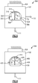
Figure 4 illustrates anexample component assembly 200 according to an embodiment. In this example, thepin 208 has a generally D-shaped cross-sectional shape. Thehole 206 has a similar D-shape. This unique pin shape provides a larger contact area in a smaller space in the radial direction. Aportion 216 of thepin 208 has a radius R1 that is substantially identical to a radius of aportion 217 of thehole 206. In one example, the radius of theportion 216 and theportion 217 are within 0.005 inches (0.127 mm) of one another. Theportion 216 of thepin 208 thus contacts thehole 206 over anarea 214 that is much larger than for pins having a different radius from the hole. - The
pin 208 has a height H. A ratio of the height H to radius R1 is less than 2. Minimizing this ratio helps to minimize the contact stress between thepin 208 and thefirst component 102. In a further embodiment, the ratio of H to R1 is between 1 and 2. In other embodiments, the ratio H to R1 may be less than 1. The height H is smaller than a height of thehole 206 to provide a clearance C for installation of thepin 208 in thehole 206. The clearance C may also accommodate manufacturing tolerances and thermal expansion. Thepin 108 may be formed from any material. In one example, thepin 108 is formed from a metallic material. In other examples, thepin 108 may be formed from a ceramic or other material. Thepin 108 may have the disclosed D-shaped cross section along an entire length of thepin 108, or along a portion of the length. -
Figure 5 illustrates anexample component assembly 300 according to another embodiment. In this example, thepin 308 has asurface 322 to that is configured to contact thehole 306 at a different point from thearea 314. Theradiused portion 316 contacts thehole 306 to support theload 111, while thesurface 322 contacts thehole 306 to support asecond load 115 in a different direction from theload 111. For example, theload 111 may be a radial load, while theload 115 is a lateral load. The direction of theloads pin 308 and thehole 306 opposite thesurface 322 to provide clearance for insertion of thepin 308. In some examples, achannel 320 is machined into thepin 308 to form thesurface 322. -
Figure 6 illustrates anexample component assembly 400 according to another embodiment. In this example, thepin 408 is at least partially hollow. Awall 409 having athickness 432 forms thepin 408 and encloses acavity 430 within thepin 408. Thecavity 430 may run the entire length of thepin 408 or for part of the length of thepin 408. This arrangement reduces radial stiffness of thepin 408. The reduced radial stiffness may add compliance to the joint for improved distribution of contact stresses. Thepin 408 must be formed from a material that is able to withstand the high temperatures of theceramic component 102. Thus, the hollow cross section of thepin 408 provides a reduced radial stiffness while still using materials that can withstand the temperature requirements of theassembly 400. -
Figure 7 illustrates anexample component assembly 500 according to another embodiment. In this example, thepin 508 is at least partially hollow. In this example, an opening in thepin 508 is arranged within theportion 516 that connects with thecavity 530. This arrangement may also provide reduced radial stiffness. -
Figure 8 illustrates anexample component assembly 600 according to another embodiment. In this example, thepin 608 has a substantially elliptical cross section. Thehole 606 may be D-shaped, or may have another shape, such as an elliptical shape. Thecurved portion 616 of thepin 608 has a radius R1. Asecond portion 618 of thepin 608 opposite theportion 616 has the same radius R1. Thus, the pin is symmetrical about aplane 640 extending along a length of thepin 608. This symmetrical arrangement may prevent mis-installation of thepin 608 in thehole 606, while still providing an increased R1 and smaller radial height. - Known attachment pins for CMC components may concentrate the load on the edge of the CMC hole, creating a bending moment when there is a difference in curvature between the CMC component and the pin. This can reduce the ultimate strength of the CMC component and lead to part fracture. The disclosed attachment pins 208, 308, 408, 508, 608 help maximize the load area on the
CMC component 102, to minimize the stresses in theCMC component 102. This arrangement provides a larger radius for the contact surface while minimizing the pin height, which reduces the space required for the pin attachment. Thus, reduced contact stresses in thecomponent 102 may be achieved within the same radial space as known circular pins. The matched radii of thepin 208 andhole 206 may substantially reduce nominal bearing contact stresses. - The disclosed pins 208, 308, 408, 508, 608 may be used for securing a variety of ceramic components. In particular, the components may be simply supported components that are in the gas path or have a pressure change across them, such as shrouds or ducts. Other example ceramic components in gas turbine engines that could use this pin arrangement may include such as BOAS segments, combustor liner panels, transition ducts, exhaust nozzle liners, blades or vanes, and separate turbine airfoil platforms.
-
Figure 9 illustrates an example blade outer air seal (BOAS)assembly 704 utilizing a pin attachment according to an embodiment. TheBOAS assembly 704 is spaced from a radially outer tip of a turbine blade, and includes aBOAS 706. TheBOAS 706 may be made up of a plurality ofseal segments 705 that are circumferentially arranged in an annulus about the central axis A of theengine 20. TheBOAS segments 705 may be monolithic bodies that are formed of a ceramic material, such as a ceramic matrix composite ("CMC") or monolithic ceramic. - The
BOAS 706 may be mounted to an engine case or structure, such as engine static structure 36 via acarrier 712. Eachseal segment 705 is a body that defines radially inner and outer sides R1, R2, respectively, first and second axial sides A1, A2, respectively, and first and second circumferential sides C1, C2 (shown inFigure 10 ), respectively. The radially inner side R1 faces in a direction toward the engine central axis A. The radially inner side R1 is thus the gas path side of the seal segment 105 that bounds a portion of the core flow path C. The first axial side A1 faces in a forward direction toward the front of the engine 20 (i.e., toward the fan 42), and the second axial side A2 faces in an aft direction toward the rear of the engine 20 (i.e., toward the exhaust end). - In the illustrated example, each
BOAS segment 705 includes afirst wall 720 and asecond wall 722. The first andsecond walls base portion 724. The first andsecond walls seal segment 705 and are axially spaced from one another. The first andsecond walls base portion 724, in one example. The first andsecond walls base portion 724 extends between the first and second axial sides A1, A2 and defines a gas path on a radially inner side and a non-gas path on a radially outer side. In this disclosure, forward, aft, upstream, downstream, axial, radial, or circumferential is in relation to the engine axis A unless stated otherwise. Thebase portion 724 may extend axially forward and/or aft of the first andsecond walls - At least one
hole 730 extends through each of the first andsecond walls holes 730 extend through the first andsecond walls carrier 712 includes afirst hole 725 and asecond hole 727. The carrier holes 725, 727 generally align circumferentially and radially with theholes 730 for securing theBOAS segment 705 to thecarrier 712. Apin 708 extends through each of the carrier holes 725, 727 and the BOAS holes 730. Thepin 708 extends in a generally axial direction and retains theBOAS segment 705 in thecarrier 712. - As can be seen in
Figure 10 , the twoholes 730 in theBOAS segment 706 are generally the same size and shape as one another. Theholes 730 in theBOAS segment 706 may be generally D-shaped to accommodate thepin 708. Theholes carrier 712 may be generally rectangular, in one example. - As shown in
Figure 11 , theholes 730 in theBOAS segment 706 includes acurved portion 716 having a radius R1 that matches a radius of a portion of thepin 708. Thepin 708 may have a generally elliptical shape, for example. In other examples, thepin 708 may have any of the cross-sectional shapes described above. - In the illustrated example, the
hole 730 has a width that is close to a width WP of thepin 708. Thehole 725 has a width Ws that is wider than the width WP or the width of thehole 730. This wider width Ws in the circumferential direction provides a large clearance in the circumferential direction. Thehole 725 provides more circumferential clearance than thehole 727. This allows thehole 727 to locate theBOAS segment 706 in the circumferential direction, while thehole 725 allows circumferential thermal expansion of thecarrier 712 relative to theBOAS segment 706. In the illustrated example, each of theholes - The disclosed pin attachment for a BOAS provides enough clearance between the top of the pin and the above case to accommodate pin rotation driven by BOAS uncurling during operation. Bearing contact stresses from the pin may be reduced because of the matching radii between the
pin 708 and theholes 730 in the BOAS, while utilizing less space in the radial direction compared to cylindrical pins. In some examples, sliding wear occurs at the interface between the pin and case, rather than the pin and BOAS, which may protect the CMC surface. This arrangement may provide tight circumferential control of a CMC BOAS relative to a metallic case, while allowing free thermal expansion within the components. - In this disclosure, "generally axially" means a direction having a vector component in the axial direction that is greater than a vector component in the circumferential direction, "generally radially" means a direction having a vector component in the radial direction that is greater than a vector component in the axial direction and "generally circumferentially" means a direction having a vector component in the circumferential direction that is greater than a vector component in the axial direction.
- Although an embodiment of this invention has been disclosed, a worker of ordinary skill in this art would recognize that certain modifications would come within the scope of this disclosure. For that reason, the following claims should be studied to determine the true scope and content of this disclosure.
Claims (15)
- A component assembly (200;300;400;500;600;704), comprising:a first component (102;705) having a first hole (206;306;406;506;606;730), the first hole (206;... ;730) having a non-circular cross section, a first portion (217;716) of the first hole (206;...;730) having a first radius of curvature (R1);a second component (104;712); anda pin (208;308;408;508;608;708) extending from the second component (104;712) and through the first hole (206;...;730), the pin (208;...;708) having a non-circular cross section, and a second portion (216;316;516;616) of the pin (208;... ;708) having a second radius of curvature (R2), wherein the first radius of curvature (R1) and the second radius of curvature (R2) are substantially the same.
- The component assembly of claim 1, wherein the first radius of curvature (R1) is within 0.005 inches (0.127 mm) of the second radius of curvature (R2).
- The component assembly of claim 1 or 2, wherein the first component (102;705) is a ceramic material, and/or the pin (208;...;708) is a metallic material.
- The component assembly of claim 1, 2 or 3, wherein the second component (104;712) has a second hole (725,727) and the pin (208;... ;708) extends through the first hole (206;... ;730) and the second hole (725,727).
- The component assembly of any preceding claim, wherein the second portion (216;...;616) of the pin (208;...;708) is configured to contact the first portion (217;716) of the first hole (206;...;730).
- The component assembly of any preceding claim, wherein the pin (208;...;708) and the first hole (206;...;730) have substantially D-shaped cross-sections.
- The component assembly of any preceding claim, wherein the pin (208;308;408;508) has a substantially flat portion (218;318) opposite the second portion (216;...;616).
- The component assembly of claim 7, wherein the substantially flat portion (218;318) is spaced from the first hole (206;306;406) to provide a clearance (C) between the pin (208;308;408;508) and the first hole (206;306;406).
- The component assembly of any of claims 1 to 5, wherein the pin (608;708) has a cross-section that is substantially symmetric about a plane (640).
- The component assembly of any preceding claim, wherein the pin (308) has a surface (322) that is configured to contact the first hole (306) at a location outside of the first portion (217;716).
- The component assembly of any preceding claim, wherein the pin (408;508) is at least partially hollow.
- The component assembly of any preceding claim, wherein the first component (102;705) is one of a blade outer air seal (706), a combustor liner, a transition duct, an exhaust nozzle panel, and an airfoil platform.
- A section of a gas turbine engine (20), comprising the component assembly of any preceding claim, wherein the second component (104;712) is statically mounted within the gas turbine engine (20).
- A blade outer air seal assembly (704), comprising:a carrier (712) having a first aperture (725);a blade outer air seal (706) having at least one segment (705) mounted in the carrier (712), the at least one segment (705) having a first wall (720) having a first hole (730); anda pin (708) extending through the first aperture (725) and through the first hole (730), the pin (708) having a non-circular cross-section.
- The blade outer air seal assembly of claim 14, wherein the carrier (712) has a second aperture (727) and a second hole (730) extends through the first wall (720), and a second pin (708) extends through the second aperture (727) and the second hole (730), wherein the second aperture (727) has a different cross section from the first aperture (725).
Priority Applications (1)
| Application Number | Priority Date | Filing Date | Title |
|---|---|---|---|
| EP25202543.2A EP4640993A3 (en) | 2020-03-13 | 2021-03-10 | Pin attachment for cmc components in a gas turbine engine |
Applications Claiming Priority (1)
| Application Number | Priority Date | Filing Date | Title |
|---|---|---|---|
| US16/817,990 US11215064B2 (en) | 2020-03-13 | 2020-03-13 | Compact pin attachment for CMC components |
Related Child Applications (1)
| Application Number | Title | Priority Date | Filing Date |
|---|---|---|---|
| EP25202543.2A Division EP4640993A3 (en) | 2020-03-13 | 2021-03-10 | Pin attachment for cmc components in a gas turbine engine |
Publications (2)
| Publication Number | Publication Date |
|---|---|
| EP3892824A1 true EP3892824A1 (en) | 2021-10-13 |
| EP3892824B1 EP3892824B1 (en) | 2025-09-17 |
Family
ID=74870760
Family Applications (2)
| Application Number | Title | Priority Date | Filing Date |
|---|---|---|---|
| EP25202543.2A Pending EP4640993A3 (en) | 2020-03-13 | 2021-03-10 | Pin attachment for cmc components in a gas turbine engine |
| EP21161855.8A Active EP3892824B1 (en) | 2020-03-13 | 2021-03-10 | Pin attachment for cmc components in a gas turbine engine |
Family Applications Before (1)
| Application Number | Title | Priority Date | Filing Date |
|---|---|---|---|
| EP25202543.2A Pending EP4640993A3 (en) | 2020-03-13 | 2021-03-10 | Pin attachment for cmc components in a gas turbine engine |
Country Status (2)
| Country | Link |
|---|---|
| US (1) | US11215064B2 (en) |
| EP (2) | EP4640993A3 (en) |
Families Citing this family (24)
| Publication number | Priority date | Publication date | Assignee | Title |
|---|---|---|---|---|
| US11773751B1 (en) | 2022-11-29 | 2023-10-03 | Rolls-Royce Corporation | Ceramic matrix composite blade track segment with pin-locating threaded insert |
| US12031443B2 (en) | 2022-11-29 | 2024-07-09 | Rolls-Royce Corporation | Ceramic matrix composite blade track segment with attachment flange cooling chambers |
| US11713694B1 (en) | 2022-11-30 | 2023-08-01 | Rolls-Royce Corporation | Ceramic matrix composite blade track segment with two-piece carrier |
| US11840936B1 (en) | 2022-11-30 | 2023-12-12 | Rolls-Royce Corporation | Ceramic matrix composite blade track segment with pin-locating shim kit |
| US11732604B1 (en) | 2022-12-01 | 2023-08-22 | Rolls-Royce Corporation | Ceramic matrix composite blade track segment with integrated cooling passages |
| US11976571B1 (en) * | 2022-12-13 | 2024-05-07 | Rtx Corporation | Machinable coating with thermal protection |
| US11885225B1 (en) | 2023-01-25 | 2024-01-30 | Rolls-Royce Corporation | Turbine blade track with ceramic matrix composite segments having attachment flange draft angles |
| US12188365B1 (en) | 2023-12-04 | 2025-01-07 | Rolls-Royce Corporation | Method and apparatus for ceramic matrix composite turbine shroud assembly |
| US12152499B1 (en) | 2023-12-04 | 2024-11-26 | Rolls-Royce Corporation | Turbine shroud segments with strip seal assemblies having dampened ends |
| US12158072B1 (en) | 2023-12-04 | 2024-12-03 | Rolls-Royce Corporation | Turbine shroud segments with damping strip seals |
| US12421862B2 (en) | 2023-12-04 | 2025-09-23 | Rolls-Royce Corporation | Turbine shroud assembly with angled cooling holes |
| US12241376B1 (en) | 2023-12-04 | 2025-03-04 | Rolls-Royce Corporation | Locating plate for use with turbine shroud assemblies |
| US12286885B1 (en) | 2023-12-04 | 2025-04-29 | Rolls-Royce Corporation | Turbine assembly with confronting vane and turbine shroud segment |
| US12286906B1 (en) | 2023-12-04 | 2025-04-29 | Rolls-Royce Corporation | Locating plate for use with turbine shroud assemblies |
| US12258867B1 (en) * | 2024-01-31 | 2025-03-25 | Rtx Corporation | Attachment for blade outer air seal |
| US12421870B1 (en) | 2024-04-30 | 2025-09-23 | Rolls-Royce Corporation | Pin mounted ceramic matrix composite heat shields with impingement cooling |
| US12215593B1 (en) | 2024-05-30 | 2025-02-04 | Rolls-Royce Corporation | Turbine shroud assembly with inter-segment damping |
| US12305525B1 (en) | 2024-05-30 | 2025-05-20 | Rolls-Royce Corporation | Turbine shroud assemblies with rod seal and strip seals |
| US12258880B1 (en) | 2024-05-30 | 2025-03-25 | Rolls-Royce Corporation | Turbine shroud assemblies with inter-segment strip seal |
| US12416241B1 (en) | 2024-05-30 | 2025-09-16 | Rolls-Royce Corporation | Turbine shroud assemblies with strip seals |
| US12410725B1 (en) | 2024-05-31 | 2025-09-09 | Rolls-Royce Corporation | Turbine shroud assemblies with air activated pistons for biasing buffer cavity seals |
| US12352176B1 (en) | 2024-05-31 | 2025-07-08 | Rolls-Royce Corporation | Turbine shroud assemblies with channels for buffer cavity seal thermal management |
| US12577881B2 (en) | 2024-05-31 | 2026-03-17 | Rolls-Royce Corporation | Turbine shroud assemblies with anti-migration seals |
| US12228044B1 (en) | 2024-06-26 | 2025-02-18 | Rolls-Royce Corporation | Turbine shroud system with ceramic matrix composite segments and dual inter-segment seals |
Citations (3)
| Publication number | Priority date | Publication date | Assignee | Title |
|---|---|---|---|---|
| US20070240423A1 (en) * | 2005-10-12 | 2007-10-18 | General Electric Company | Bolting configuration for joining ceramic combustor liner to metal mounting attachments |
| EP3196553A1 (en) * | 2016-01-15 | 2017-07-26 | Rolls-Royce plc | Gas turbine combustion chamber arrangement |
| EP3450694A2 (en) * | 2017-08-30 | 2019-03-06 | General Electric Company | Flow path assemblies for gas turbine engines and assembly methods therefore |
Family Cites Families (18)
| Publication number | Priority date | Publication date | Assignee | Title |
|---|---|---|---|---|
| US5163817A (en) * | 1989-10-16 | 1992-11-17 | United Technologies Corporation | Rotor blade retention |
| US5017092A (en) * | 1989-10-16 | 1991-05-21 | United Technologies Corporation | Rotor blade retention |
| US6884026B2 (en) | 2002-09-30 | 2005-04-26 | General Electric Company | Turbine engine shroud assembly including axially floating shroud segment |
| US6895761B2 (en) | 2002-12-20 | 2005-05-24 | General Electric Company | Mounting assembly for the aft end of a ceramic matrix composite liner in a gas turbine engine combustor |
| US7494317B2 (en) | 2005-06-23 | 2009-02-24 | Siemens Energy, Inc. | Ring seal attachment system |
| US7726936B2 (en) * | 2006-07-25 | 2010-06-01 | Siemens Energy, Inc. | Turbine engine ring seal |
| US7832972B2 (en) | 2008-03-05 | 2010-11-16 | United Technologies Corporation | Internal pocket fastener system for ceramic matrix composites |
| US9879558B2 (en) * | 2013-02-07 | 2018-01-30 | United Technologies Corporation | Low leakage multi-directional interface for a gas turbine engine |
| BR112016028858A2 (en) | 2014-06-12 | 2017-08-22 | Gen Electric | ? suspension and base tube assemblies? |
| US9587517B2 (en) | 2014-12-29 | 2017-03-07 | Rolls-Royce North American Technologies, Inc. | Blade track assembly with turbine tip clearance control |
| FR3033825B1 (en) * | 2015-03-16 | 2018-09-07 | Safran Aircraft Engines | TURBINE RING ASSEMBLY OF CERAMIC MATRIX COMPOSITE MATERIAL |
| US10030541B2 (en) | 2015-07-01 | 2018-07-24 | Rolls-Royce North American Technologies Inc. | Turbine shroud with clamped flange attachment |
| US10301960B2 (en) | 2015-07-13 | 2019-05-28 | General Electric Company | Shroud assembly for gas turbine engine |
| US10227880B2 (en) | 2015-11-10 | 2019-03-12 | General Electric Company | Turbine blade attachment mechanism |
| FR3045716B1 (en) * | 2015-12-18 | 2018-01-26 | Safran Aircraft Engines | TURBINE RING ASSEMBLY WITH COLD ELASTIC SUPPORT |
| FR3045715B1 (en) * | 2015-12-18 | 2018-01-26 | Safran Aircraft Engines | TURBINE RING ASSEMBLY WITH COLD AND HOT HOLDING |
| FR3068071B1 (en) * | 2017-06-26 | 2019-11-08 | Safran Aircraft Engines | ASSEMBLY FOR THE PALLET CONNECTION BETWEEN A TURBINE HOUSING AND AN ANNULAR TURBOMACHINE ELEMENT |
| US10677075B2 (en) | 2018-05-04 | 2020-06-09 | General Electric Company | Composite airfoil assembly for an interdigitated rotor |
-
2020
- 2020-03-13 US US16/817,990 patent/US11215064B2/en active Active
-
2021
- 2021-03-10 EP EP25202543.2A patent/EP4640993A3/en active Pending
- 2021-03-10 EP EP21161855.8A patent/EP3892824B1/en active Active
Patent Citations (3)
| Publication number | Priority date | Publication date | Assignee | Title |
|---|---|---|---|---|
| US20070240423A1 (en) * | 2005-10-12 | 2007-10-18 | General Electric Company | Bolting configuration for joining ceramic combustor liner to metal mounting attachments |
| EP3196553A1 (en) * | 2016-01-15 | 2017-07-26 | Rolls-Royce plc | Gas turbine combustion chamber arrangement |
| EP3450694A2 (en) * | 2017-08-30 | 2019-03-06 | General Electric Company | Flow path assemblies for gas turbine engines and assembly methods therefore |
Also Published As
| Publication number | Publication date |
|---|---|
| EP4640993A2 (en) | 2025-10-29 |
| EP4640993A3 (en) | 2026-04-22 |
| US20210285334A1 (en) | 2021-09-16 |
| EP3892824B1 (en) | 2025-09-17 |
| US11215064B2 (en) | 2022-01-04 |
Similar Documents
| Publication | Publication Date | Title |
|---|---|---|
| EP3892824B1 (en) | Pin attachment for cmc components in a gas turbine engine | |
| EP3779131B1 (en) | Flow path component assembly and corresponding turbine section for a gas turbine engine | |
| EP3819475B1 (en) | Blade outer air seal arrangement and method of sealing | |
| EP3792453B1 (en) | Cmc boas assembly | |
| US11255209B2 (en) | CMC BOAS arrangement | |
| EP4056811A1 (en) | Scalloped mateface seal arrangement for cmc platforms | |
| US11248480B2 (en) | Intersegment seal for CMC boas assembly | |
| US11808154B2 (en) | CMC component flow discourager flanges | |
| US20220049628A1 (en) | Gas turbine engine component | |
| EP3739168B1 (en) | Gas turbine boas assembly and method | |
| US10746049B2 (en) | Gas turbine engine case including bearing compartment | |
| EP3722569A1 (en) | Blade outer air seal and turbine section | |
| EP3825518B1 (en) | Vane retention assembly | |
| EP4086435B1 (en) | Variable thickness machinable coating for platform seals | |
| EP4086434A2 (en) | Cmc vane with platform cover | |
| EP4056812A1 (en) | Chevron grooved mateface seal | |
| US11125099B2 (en) | Boas arrangement with double dovetail attachments |
Legal Events
| Date | Code | Title | Description |
|---|---|---|---|
| PUAI | Public reference made under article 153(3) epc to a published international application that has entered the european phase |
Free format text: ORIGINAL CODE: 0009012 |
|
| STAA | Information on the status of an ep patent application or granted ep patent |
Free format text: STATUS: THE APPLICATION HAS BEEN PUBLISHED |
|
| AK | Designated contracting states |
Kind code of ref document: A1 Designated state(s): AL AT BE BG CH CY CZ DE DK EE ES FI FR GB GR HR HU IE IS IT LI LT LU LV MC MK MT NL NO PL PT RO RS SE SI SK SM TR |
|
| STAA | Information on the status of an ep patent application or granted ep patent |
Free format text: STATUS: REQUEST FOR EXAMINATION WAS MADE |
|
| 17P | Request for examination filed |
Effective date: 20220408 |
|
| RBV | Designated contracting states (corrected) |
Designated state(s): AL AT BE BG CH CY CZ DE DK EE ES FI FR GB GR HR HU IE IS IT LI LT LU LV MC MK MT NL NO PL PT RO RS SE SI SK SM TR |
|
| STAA | Information on the status of an ep patent application or granted ep patent |
Free format text: STATUS: EXAMINATION IS IN PROGRESS |
|
| 17Q | First examination report despatched |
Effective date: 20230329 |
|
| RAP3 | Party data changed (applicant data changed or rights of an application transferred) |
Owner name: RTX CORPORATION |
|
| GRAP | Despatch of communication of intention to grant a patent |
Free format text: ORIGINAL CODE: EPIDOSNIGR1 |
|
| STAA | Information on the status of an ep patent application or granted ep patent |
Free format text: STATUS: GRANT OF PATENT IS INTENDED |
|
| INTG | Intention to grant announced |
Effective date: 20250414 |
|
| GRAS | Grant fee paid |
Free format text: ORIGINAL CODE: EPIDOSNIGR3 |
|
| GRAA | (expected) grant |
Free format text: ORIGINAL CODE: 0009210 |
|
| STAA | Information on the status of an ep patent application or granted ep patent |
Free format text: STATUS: THE PATENT HAS BEEN GRANTED |
|
| AK | Designated contracting states |
Kind code of ref document: B1 Designated state(s): AL AT BE BG CH CY CZ DE DK EE ES FI FR GB GR HR HU IE IS IT LI LT LU LV MC MK MT NL NO PL PT RO RS SE SI SK SM TR |
|
| REG | Reference to a national code |
Ref country code: GB Ref legal event code: FG4D |
|
| REG | Reference to a national code |
Ref country code: CH Ref legal event code: EP |
|
| REG | Reference to a national code |
Ref country code: DE Ref legal event code: R096 Ref document number: 602021038600 Country of ref document: DE |
|
| REG | Reference to a national code |
Ref country code: IE Ref legal event code: FG4D |
|
| PG25 | Lapsed in a contracting state [announced via postgrant information from national office to epo] |
Ref country code: NO Free format text: LAPSE BECAUSE OF FAILURE TO SUBMIT A TRANSLATION OF THE DESCRIPTION OR TO PAY THE FEE WITHIN THE PRESCRIBED TIME-LIMIT Effective date: 20251217 |
|
| REG | Reference to a national code |
Ref country code: LT Ref legal event code: MG9D |
|
| PG25 | Lapsed in a contracting state [announced via postgrant information from national office to epo] |
Ref country code: FI Free format text: LAPSE BECAUSE OF FAILURE TO SUBMIT A TRANSLATION OF THE DESCRIPTION OR TO PAY THE FEE WITHIN THE PRESCRIBED TIME-LIMIT Effective date: 20250917 |
|
| PG25 | Lapsed in a contracting state [announced via postgrant information from national office to epo] |
Ref country code: HR Free format text: LAPSE BECAUSE OF FAILURE TO SUBMIT A TRANSLATION OF THE DESCRIPTION OR TO PAY THE FEE WITHIN THE PRESCRIBED TIME-LIMIT Effective date: 20250917 |
|
| PG25 | Lapsed in a contracting state [announced via postgrant information from national office to epo] |
Ref country code: GR Free format text: LAPSE BECAUSE OF FAILURE TO SUBMIT A TRANSLATION OF THE DESCRIPTION OR TO PAY THE FEE WITHIN THE PRESCRIBED TIME-LIMIT Effective date: 20251218 |
|
| PG25 | Lapsed in a contracting state [announced via postgrant information from national office to epo] |
Ref country code: SE Free format text: LAPSE BECAUSE OF FAILURE TO SUBMIT A TRANSLATION OF THE DESCRIPTION OR TO PAY THE FEE WITHIN THE PRESCRIBED TIME-LIMIT Effective date: 20250917 |
|
| REG | Reference to a national code |
Ref country code: NL Ref legal event code: MP Effective date: 20250917 |
|
| PG25 | Lapsed in a contracting state [announced via postgrant information from national office to epo] |
Ref country code: LV Free format text: LAPSE BECAUSE OF FAILURE TO SUBMIT A TRANSLATION OF THE DESCRIPTION OR TO PAY THE FEE WITHIN THE PRESCRIBED TIME-LIMIT Effective date: 20250917 |
|
| PG25 | Lapsed in a contracting state [announced via postgrant information from national office to epo] |
Ref country code: BG Free format text: LAPSE BECAUSE OF FAILURE TO SUBMIT A TRANSLATION OF THE DESCRIPTION OR TO PAY THE FEE WITHIN THE PRESCRIBED TIME-LIMIT Effective date: 20250917 |
|
| PG25 | Lapsed in a contracting state [announced via postgrant information from national office to epo] |
Ref country code: RS Free format text: LAPSE BECAUSE OF FAILURE TO SUBMIT A TRANSLATION OF THE DESCRIPTION OR TO PAY THE FEE WITHIN THE PRESCRIBED TIME-LIMIT Effective date: 20251217 |
|
| PG25 | Lapsed in a contracting state [announced via postgrant information from national office to epo] |
Ref country code: NL Free format text: LAPSE BECAUSE OF FAILURE TO SUBMIT A TRANSLATION OF THE DESCRIPTION OR TO PAY THE FEE WITHIN THE PRESCRIBED TIME-LIMIT Effective date: 20250917 |
|
| REG | Reference to a national code |
Ref country code: AT Ref legal event code: MK05 Ref document number: 1838431 Country of ref document: AT Kind code of ref document: T Effective date: 20250917 |
|
| PG25 | Lapsed in a contracting state [announced via postgrant information from national office to epo] |
Ref country code: SM Free format text: LAPSE BECAUSE OF FAILURE TO SUBMIT A TRANSLATION OF THE DESCRIPTION OR TO PAY THE FEE WITHIN THE PRESCRIBED TIME-LIMIT Effective date: 20250917 |
|
| PGFP | Annual fee paid to national office [announced via postgrant information from national office to epo] |
Ref country code: GB Payment date: 20260219 Year of fee payment: 6 |
|
| PG25 | Lapsed in a contracting state [announced via postgrant information from national office to epo] |
Ref country code: ES Free format text: LAPSE BECAUSE OF FAILURE TO SUBMIT A TRANSLATION OF THE DESCRIPTION OR TO PAY THE FEE WITHIN THE PRESCRIBED TIME-LIMIT Effective date: 20250917 |
|
| PGFP | Annual fee paid to national office [announced via postgrant information from national office to epo] |
Ref country code: DE Payment date: 20260219 Year of fee payment: 6 |
|
| PG25 | Lapsed in a contracting state [announced via postgrant information from national office to epo] |
Ref country code: AT Free format text: LAPSE BECAUSE OF FAILURE TO SUBMIT A TRANSLATION OF THE DESCRIPTION OR TO PAY THE FEE WITHIN THE PRESCRIBED TIME-LIMIT Effective date: 20250917 |
|
| PG25 | Lapsed in a contracting state [announced via postgrant information from national office to epo] |
Ref country code: IT Free format text: LAPSE BECAUSE OF FAILURE TO SUBMIT A TRANSLATION OF THE DESCRIPTION OR TO PAY THE FEE WITHIN THE PRESCRIBED TIME-LIMIT Effective date: 20250917 |
|
| PG25 | Lapsed in a contracting state [announced via postgrant information from national office to epo] |
Ref country code: IS Free format text: LAPSE BECAUSE OF FAILURE TO SUBMIT A TRANSLATION OF THE DESCRIPTION OR TO PAY THE FEE WITHIN THE PRESCRIBED TIME-LIMIT Effective date: 20260117 |
|
| PGFP | Annual fee paid to national office [announced via postgrant information from national office to epo] |
Ref country code: FR Payment date: 20260220 Year of fee payment: 6 |
|
| PG25 | Lapsed in a contracting state [announced via postgrant information from national office to epo] |
Ref country code: CZ Free format text: LAPSE BECAUSE OF FAILURE TO SUBMIT A TRANSLATION OF THE DESCRIPTION OR TO PAY THE FEE WITHIN THE PRESCRIBED TIME-LIMIT Effective date: 20250917 Ref country code: PT Free format text: LAPSE BECAUSE OF FAILURE TO SUBMIT A TRANSLATION OF THE DESCRIPTION OR TO PAY THE FEE WITHIN THE PRESCRIBED TIME-LIMIT Effective date: 20260119 |
|
| PG25 | Lapsed in a contracting state [announced via postgrant information from national office to epo] |
Ref country code: PL Free format text: LAPSE BECAUSE OF FAILURE TO SUBMIT A TRANSLATION OF THE DESCRIPTION OR TO PAY THE FEE WITHIN THE PRESCRIBED TIME-LIMIT Effective date: 20250917 |
|
| PG25 | Lapsed in a contracting state [announced via postgrant information from national office to epo] |
Ref country code: SK Free format text: LAPSE BECAUSE OF FAILURE TO SUBMIT A TRANSLATION OF THE DESCRIPTION OR TO PAY THE FEE WITHIN THE PRESCRIBED TIME-LIMIT Effective date: 20250917 Ref country code: EE Free format text: LAPSE BECAUSE OF FAILURE TO SUBMIT A TRANSLATION OF THE DESCRIPTION OR TO PAY THE FEE WITHIN THE PRESCRIBED TIME-LIMIT Effective date: 20250917 |