EP3892541B1 - Personal heating ventilation and air conditioning system in aircraft seat - Google Patents
Personal heating ventilation and air conditioning system in aircraft seat Download PDFInfo
- Publication number
- EP3892541B1 EP3892541B1 EP21166984.1A EP21166984A EP3892541B1 EP 3892541 B1 EP3892541 B1 EP 3892541B1 EP 21166984 A EP21166984 A EP 21166984A EP 3892541 B1 EP3892541 B1 EP 3892541B1
- Authority
- EP
- European Patent Office
- Prior art keywords
- seat
- heating
- branch
- sub
- branches
- Prior art date
- Legal status (The legal status is an assumption and is not a legal conclusion. Google has not performed a legal analysis and makes no representation as to the accuracy of the status listed.)
- Active
Links
Images

Classifications
-
- B—PERFORMING OPERATIONS; TRANSPORTING
- B64—AIRCRAFT; AVIATION; COSMONAUTICS
- B64D—EQUIPMENT FOR FITTING IN OR TO AIRCRAFT; FLIGHT SUITS; PARACHUTES; ARRANGEMENT OR MOUNTING OF POWER PLANTS OR PROPULSION TRANSMISSIONS IN AIRCRAFT
- B64D13/00—Arrangements or adaptations of air-treatment apparatus for aircraft crew or passengers, or freight space
- B64D13/06—Arrangements or adaptations of air-treatment apparatus for aircraft crew or passengers, or freight space the air being conditioned
- B64D13/08—Arrangements or adaptations of air-treatment apparatus for aircraft crew or passengers, or freight space the air being conditioned the air being heated or cooled
-
- B—PERFORMING OPERATIONS; TRANSPORTING
- B60—VEHICLES IN GENERAL
- B60N—SEATS SPECIALLY ADAPTED FOR VEHICLES; VEHICLE PASSENGER ACCOMMODATION NOT OTHERWISE PROVIDED FOR
- B60N2/00—Seats specially adapted for vehicles; Arrangement or mounting of seats in vehicles
- B60N2/56—Heating or ventilating devices
- B60N2/5607—Heating or ventilating devices characterised by convection
- B60N2/5621—Heating or ventilating devices characterised by convection by air
- B60N2/5635—Heating or ventilating devices characterised by convection by air coming from the passenger compartment
-
- B—PERFORMING OPERATIONS; TRANSPORTING
- B60—VEHICLES IN GENERAL
- B60N—SEATS SPECIALLY ADAPTED FOR VEHICLES; VEHICLE PASSENGER ACCOMMODATION NOT OTHERWISE PROVIDED FOR
- B60N2/00—Seats specially adapted for vehicles; Arrangement or mounting of seats in vehicles
- B60N2/56—Heating or ventilating devices
- B60N2/5607—Heating or ventilating devices characterised by convection
- B60N2/5621—Heating or ventilating devices characterised by convection by air
- B60N2/5657—Heating or ventilating devices characterised by convection by air blown towards the seat surface
-
- B—PERFORMING OPERATIONS; TRANSPORTING
- B60—VEHICLES IN GENERAL
- B60N—SEATS SPECIALLY ADAPTED FOR VEHICLES; VEHICLE PASSENGER ACCOMMODATION NOT OTHERWISE PROVIDED FOR
- B60N2/00—Seats specially adapted for vehicles; Arrangement or mounting of seats in vehicles
- B60N2/56—Heating or ventilating devices
- B60N2/5678—Heating or ventilating devices characterised by electrical systems
-
- B—PERFORMING OPERATIONS; TRANSPORTING
- B64—AIRCRAFT; AVIATION; COSMONAUTICS
- B64D—EQUIPMENT FOR FITTING IN OR TO AIRCRAFT; FLIGHT SUITS; PARACHUTES; ARRANGEMENT OR MOUNTING OF POWER PLANTS OR PROPULSION TRANSMISSIONS IN AIRCRAFT
- B64D11/00—Passenger or crew accommodation; Flight-deck installations not otherwise provided for
- B64D11/06—Arrangements of seats, or adaptations or details specially adapted for aircraft seats
- B64D11/0626—Arrangements of seats, or adaptations or details specially adapted for aircraft seats with individual temperature or ventilation control
Definitions
- the present disclosure relates to aircraft seating arrangements and, in particular, personal heating ventilation and air conditioning systems in aircraft seats.
- climate control of living and working spaces is traditionally provided to relatively large areas, including unoccupied zones, such as entire buildings, offices or suites of rooms within a building.
- unoccupied zones such as entire buildings, offices or suites of rooms within a building.
- the entire cabin is usually cooled or heated as a unit.
- it can be more beneficial to have more selective and dedicated control over the near environment of each passenger For example, it is often desirable to provide a personal climate control to a passenger for an improved comfort and flight experience.
- One temperature setpoint is controlled by the cabin crew for the whole cabin area, including unoccupied zones such as volume above heads, the galleys or the aisles.
- the passenger's back and other pressure points may remain sweaty while being seated for a few flight hours or after being exposed to hot outdoor conditions of a summer day (e.g. when boarding the aircraft). In winter, the gaspers may provide cold air which may be uncomfortable after boarding the aircraft on a cold winter day.
- a personal heating ventilation and air conditioning system for an aircraft seat.
- the personal HVAC system includes a plurality of aircraft seats, a heating/cooling device disposed on the plurality of aircraft seats, a plurality of branches configured to provide a plurality of flow paths from the heating/cooling device, a plurality of sub-branches provided within the plurality of aircraft seats, wherein the plurality of sub-branches are configured to provide flow from the plurality of branches through the plurality of aircraft seats, and means for expelling air from the plurality of sub-branches to an interior surface of the plurality of aircraft seats .
- the heating/cooling device may be one of a combination at least one thermoelectric device and at least one fan, or a combination of at least one heating pad and at least one fan.
- the means for expelling air may include one of at least one outlet and/or a plurality of holes.
- the plurality of aircraft seats may include at least one of a seat cushion, a seat back support, a seat neck support and/or a headrest.
- the plurality of aircraft seats may include a first seat, a second seat and a third seat.
- the plurality of branches may include a first branch, a second branch, and a third branch.
- the first branch may have a first sub-branch and a second sub-branch
- the second branch may have a first sub-branch and a second sub-branch
- the third branch may have a first sub-branch and a second sub-branch.
- the heating/cooling device may be controlled by a controller.
- the system may further include manual mechanic controls for adjusting the heating/cooling device through the controller; and/or a tablet connected to an advanced control system for adjusting the heating/cooling device; and/or a smart phone connected to an advanced control system for adjusting the heating/cooling device.
- the plurality of sub-branches may be adjustable.
- the plurality of aircraft seats may include a material provided over the seat, and wherein there may be an air spacer material provided between the material and the means for expelling air.
- an aircraft cabin including at least one personal HVAC system as described above.
- a method that includes providing a plurality of aircraft seats, providing a heating/cooling device on the plurality of aircraft seats, providing a plurality of branches that provide a plurality of flow paths from the heating/cooling device, providing a plurality of sub-branches within the plurality of aircraft seats, wherein the plurality of sub-branches provide flow from the plurality of branches through the plurality of aircraft seats, and expelling air from the plurality of sub-branches to an interior surface of the plurality of aircraft seats.
- the seating arrangement 10 as shown in this example, relates to seats for use in an aircraft.
- the seating arrangement 10 may include a first seat 10A, a second seat 10B and a third seat 10C.
- the seating arrangement 10 may include a first seat 10A, a second seat 10B and a third seat 10C.
- Figure 1 is not restricted to a three seat arrangement, such as the seating arrangement 10 including a first seat 10A, a second seat 10B and a third seat 10C.
- a heating/cooling device 100 on the underside of second seat 10B.
- the heating/cooling device 100 may be provided on the underside of more than three seats where necessary.
- the heating/cooling device is provided on the underside of the middle seat (i.e., the second seat 10B).
- the heating/cooling device 100 may include a first outlet, a second outlet and a third outlet (not shown).
- the first outlet may be connected to a first branch 101A providing a first flow path.
- the second outlet may be connected to a second branch 101B providing a second flow path.
- the third outlet may be connected to a third branch 101C providing a third flow path.
- the first, second and third flow path allow for heating or cooling air to flow through the first, second and third branches 101A, 101B and 101C.
- the first branch 101A may split into a first sub-branch 102A and a second sub-branch 102B which may provide flow through a seat cushion, a seat back support and a seat neck support of the first seat 10.
- the second branch 101B may split into a first sub-branch 103A and a second sub-branch 103B which may provide flow through a seat cushion, a seat back support and a seat neck support of the second seat 10B.
- the third branch 101C may also split into a first sub-branch 104A and a second sub-branch 104B which may provide flow through a seat cushion, a seat back support and a seat neck support of the third seat 10C.
- outlets O1, O2, O3, O4, O5 and O6 on the sub-branches 102A, 102B, 103A, 103B, 104A and 104B.
- the outlets O1...O6 are provided to expel air to an interior surface of two or more of the first seat 10A, the second seat 10B and the third seat 10C.
- the outlets 01...06 are directed to expel air to the seat back support through nozzles (not shown) above the shoulders.
- the outlets O1...O6 could also expel air through the seat neck support, entire seat back support and/or the seat cushion.
- the sub-branches 102A, 102B, 103A, 103B, 104A and 104B may include a plurality of holes along their surfaces to expel air from the sub-branches 102A, 102B, 103A, 103B, 104A and 104B. This would allow for air to be expelled alone their surfaces to one or more of the seat cushion, seat back support and seat neck support.
- the sub-branches 102A, 102B, 103A, 103B, 104A and 104B may also adjust with a telescopic arm with the adjustment of the seat neck support.
- the sub-branches 102A, 102B, 103A, 103B, 104A and 104B when supplying air to the back of the head are designed to be adjustable to passengers of varying sizes.
- the design is integrated in the headrest.
- the assembly may be composed of an air spacer material and perforated leather similar to the seat cushion assembly described below.
- FIG. 2 shows an example of the heating/cooling device 100 of Figure 1 .
- the heating/cooling device 100 includes the first branch 101A, the second branch 101B and the third branch 101C.
- a cross-section of the exemplary heat exchanger 100 can be seen also in Figure 2 .
- the heating/cooling device 100 is a layer of thermoelectric devices for conditioning the air.
- the heating/cooling device 100 can be dedicated to one seat only and duplicated for each seat.
- Another alternative, or additional feature, of the heating/cooling device 100 may be a combination of convective cooling with fans (not shown) only and resistive heating with heating pads (not shown).
- the heating pads can be integrated in the seat cushion and seat back support.
- the heating/cooling device could also be used as a cooling purposes only with a fan (not shown) delivering air to the different areas. Further, the fans (not shown) may also be directly integrated in each area; seat cushion, seat back support, seat neck support and headrest.
- the heating/cooling device may comprise a thermoelectric based heat pump configuration, such as that described in US 2018/0216855 .
- the heating/cooling device 100 can be adjusted by a passenger when sitting in, for example, one of the first seat 10A, the second seat 10B or the third seat 10C.
- Controls may be electrically connected to the heating/cooling device 100 to alter the heating and/or cooling of the specific seat in which the passenger is sat.
- the passenger could manually adjust the heating and/or cooling from the seat in which they are sat by pressing the controls (not shown).
- a tablet or smart phone may be connected to an advanced control system (not shown) in order to adjust the heating and/or cooling on the seat in which the passenger is sat.
- the seat 20 includes a seat cushion 24, a seat back support 23, a seat neck support 22 and a seat head support 21.
- the sub-branches 102A, 102B, 103A, 103B, 104A and 104B could be provided throughout the seat cushion 24, the seat back support 23, the seat neck support 22 and the seat head support 21.
- the sub-branches 102A, 102B, 103A, 103B, 104A and 104B are provided in an adjustable zone (e.g. the seat head support 21)
- the sub-branches 102A, 102B, 103A, 103B, 104A and 104B can also adjust with movement of the adjustable zone. Therefore, the passenger can enjoy the heating/cooling after adjusting for comfort.
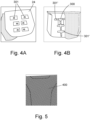
- FIGS 4A and 4B show an example of an air distribution pad 300 that can be used in addition to the first branch 101A, second branch 101B and third branch 101C of Figure 1 .
- the air distribution pad 300 is shown here to be in the interior of the seat cushion.
- the air distribution pad 300 may include one or more nozzles 301 for expelling air to the seat cushion 24.
- the air distribution pad 300 may include one or more branches 301' for providing air flow to the one or more nozzles 301.
- the air distribution pad 300 may be fluidly connected to the first branch 101A, the second branch 101B and/or the third branch 101C shown in Figure 1 .
- the air distribution pad 300 alternatively may be fluidly connected to the sub-branches 102A, 102B, 103A, 103B, 104A and 104B.
- Figure 5 shows an example of the material 400 which is provided over the seat.
- the material 400 may be perforated to allow for the air to expel through the seat material 400.
- the material 400 may be perforated leather.
- the material 400 is not limited to leather.
- there may be provided an air spacer material (not shown) between the material 400 and the outlets 01... 06 or plurality of holed that expel air. In this way, the air spacer material acts as a mesh to prevent passengers from blocking the outlet whilst sitting in the seat.
Landscapes
- Engineering & Computer Science (AREA)
- Aviation & Aerospace Engineering (AREA)
- Transportation (AREA)
- Mechanical Engineering (AREA)
- Health & Medical Sciences (AREA)
- General Health & Medical Sciences (AREA)
- Pulmonology (AREA)
- Chair Legs, Seat Parts, And Backrests (AREA)
- Air-Conditioning For Vehicles (AREA)
Description
- The present disclosure relates to aircraft seating arrangements and, in particular, personal heating ventilation and air conditioning systems in aircraft seats.
- Climate control of living and working spaces is traditionally provided to relatively large areas, including unoccupied zones, such as entire buildings, offices or suites of rooms within a building. In the case of vehicles, such as aircrafts, the entire cabin is usually cooled or heated as a unit. However, there are many situations in which it can be more beneficial to have more selective and dedicated control over the near environment of each passenger. For example, it is often desirable to provide a personal climate control to a passenger for an improved comfort and flight experience.
- Currently, passengers on commercial aircrafts have control on the gaspers providing fresh air from the above head area. The small nozzles are difficult to reach and adjust to meet the passenger's needs in terms of flow and direction. One temperature setpoint is controlled by the cabin crew for the whole cabin area, including unoccupied zones such as volume above heads, the galleys or the aisles.
- Further, even with the gaspers oriented towards the head and torso, the passenger's back and other pressure points may remain sweaty while being seated for a few flight hours or after being exposed to hot outdoor conditions of a summer day (e.g. when boarding the aircraft). In winter, the gaspers may provide cold air which may be uncomfortable after boarding the aircraft on a cold winter day.
- For such reasons, various types of personal seat control systems were developed mainly in the automotive sector. However, there is a need for an improved control device for a personalised micro-climate in aircraft seats.
- Various personal HVAC systems are disclosed in
WO 2020 128444 A1 ,EP 3 782 852 A1 ,US 2009 218855 A1 andWO 2004 020231 A1 . - In one aspect, there is provided a personal heating ventilation and air conditioning system (HVAC) for an aircraft seat. The personal HVAC system includes a plurality of aircraft seats, a heating/cooling device disposed on the plurality of aircraft seats, a plurality of branches configured to provide a plurality of flow paths from the heating/cooling device, a plurality of sub-branches provided within the plurality of aircraft seats, wherein the plurality of sub-branches are configured to provide flow from the plurality of branches through the plurality of aircraft seats, and means for expelling air from the plurality of sub-branches to an interior surface of the plurality of aircraft seats .
- The heating/cooling device may be one of a combination at least one thermoelectric device and at least one fan, or a combination of at least one heating pad and at least one fan.
- The means for expelling air may include one of at least one outlet and/or a plurality of holes.
- Further, the plurality of aircraft seats may include at least one of a seat cushion, a seat back support, a seat neck support and/or a headrest. The plurality of aircraft seats may include a first seat, a second seat and a third seat.
- Preferably, the plurality of branches may include a first branch, a second branch, and a third branch. The first branch may have a first sub-branch and a second sub-branch, and the second branch may have a first sub-branch and a second sub-branch, and the third branch may have a first sub-branch and a second sub-branch.
- The heating/cooling device may be controlled by a controller. Preferably, the system may further include manual mechanic controls for adjusting the heating/cooling device through the controller; and/or a tablet connected to an advanced control system for adjusting the heating/cooling device; and/or a smart phone connected to an advanced control system for adjusting the heating/cooling device.
- Further, the plurality of sub-branches may be adjustable.
- Preferably, the plurality of aircraft seats may include a material provided over the seat, and wherein there may be an air spacer material provided between the material and the means for expelling air.
- In another aspect, there is provided an aircraft cabin including at least one personal HVAC system as described above.
- In a further aspect, there is provided a method that includes providing a plurality of aircraft seats, providing a heating/cooling device on the plurality of aircraft seats, providing a plurality of branches that provide a plurality of flow paths from the heating/cooling device, providing a plurality of sub-branches within the plurality of aircraft seats, wherein the plurality of sub-branches provide flow from the plurality of branches through the plurality of aircraft seats, and expelling air from the plurality of sub-branches to an interior surface of the plurality of aircraft seats.
-
-
Figure 1 shows an example of a seating arrangement with a personal heating ventilation and air conditioning (HVAC) system. -
Figure 2 shows an assembly composed of thermoelectric devices, heat sinks and fans, both from a bird's eye view and as a cross section, for use in the seating arrangement shown inFigure 1 . -
Figure 3 shows an example of a seat that may be used in the seating arrangement shown inFigure 1 . -
Figure 4A shows the interior of the seat cushion shown in the seat ofFigure 3 . -
Figure 4B shows an example of another side of the interior of the seat cushion shown in the seat ofFigure 3 . -
Figure 5 shows an example of material used to cover the seat shown inFigure 3 . - Referring now to
Figure 1 , there is shown an example of aseating arrangement 10. Theseating arrangement 10, as shown in this example, relates to seats for use in an aircraft. As shown inFigure 1 , theseating arrangement 10 may include afirst seat 10A, asecond seat 10B and athird seat 10C. Although in the example shown inFigure 1 , there are threeseats seating arrangement 10, it is envisaged that there could be any number of seats greater than one that are required for the aircraft. - If the row of seats on the desired aircraft requires more than three seats in the seating arrangement, it is envisaged that there may be less than, or more than, three seats, but at least two seats. Therefore,
Figure 1 is not restricted to a three seat arrangement, such as theseating arrangement 10 including afirst seat 10A, asecond seat 10B and athird seat 10C. - As shown in
Figure 1 , there may be provided a heating/cooling device 100 on the underside ofsecond seat 10B. Again, as discussed above, the heating/cooling device 100 may be provided on the underside of more than three seats where necessary. Further, although there is only one heating/cooling device 100 shown inFigure 1 , it is envisaged that there may be more than one heating/cooling device 100 on any number of desired seats. In the example shown inFigure 1 , the heating/cooling device is provided on the underside of the middle seat (i.e., thesecond seat 10B). - In the example shown in
Figure 1 , the heating/cooling device 100 may include a first outlet, a second outlet and a third outlet (not shown). The first outlet may be connected to afirst branch 101A providing a first flow path. The second outlet may be connected to asecond branch 101B providing a second flow path. The third outlet may be connected to athird branch 101C providing a third flow path. The first, second and third flow path allow for heating or cooling air to flow through the first, second andthird branches - Also, as shown in
Figure 1 , thefirst branch 101A may split into afirst sub-branch 102A and asecond sub-branch 102B which may provide flow through a seat cushion, a seat back support and a seat neck support of thefirst seat 10. Similarly, thesecond branch 101B may split into afirst sub-branch 103A and asecond sub-branch 103B which may provide flow through a seat cushion, a seat back support and a seat neck support of thesecond seat 10B. Thethird branch 101C may also split into afirst sub-branch 104A and asecond sub-branch 104B which may provide flow through a seat cushion, a seat back support and a seat neck support of thethird seat 10C. - In an example shown in
Figure 1 , there are provided outlets O1, O2, O3, O4, O5 and O6 on thesub-branches first seat 10A, thesecond seat 10B and thethird seat 10C. In the example shown inFigure 1 , theoutlets 01...06 are directed to expel air to the seat back support through nozzles (not shown) above the shoulders. However, it is envisaged that the outlets O1...O6 could also expel air through the seat neck support, entire seat back support and/or the seat cushion. - Although not shown in
Figure 1 , and as an alternative, or in addition to the outlets O1...O6 described above, thesub-branches sub-branches sub-branches sub-branches sub-branches -
Figure 2 shows an example of the heating/cooling device 100 ofFigure 1 . Here, it can be seen that the heating/cooling device 100 includes thefirst branch 101A, thesecond branch 101B and thethird branch 101C. A cross-section of theexemplary heat exchanger 100 can be seen also inFigure 2 . In this example, there is provided a layer ofthermoelectric devices 11,heat sinks 12 and heat rejection side-blower 13. - These layers provide for active cooling/heating for expelled air through the
first branch 101A, thesecond branch 101B and thethird branch 101C. In the example shown inFigure 2 , the heating/cooling device 100 is a layer of thermoelectric devices for conditioning the air. Alternatively, but not part of the claimed invention, the heating/cooling device 100 can be dedicated to one seat only and duplicated for each seat. Another alternative, or additional feature, of the heating/cooling device 100 may be a combination of convective cooling with fans (not shown) only and resistive heating with heating pads (not shown). As an example, the heating pads can be integrated in the seat cushion and seat back support. The heating/cooling device could also be used as a cooling purposes only with a fan (not shown) delivering air to the different areas. Further, the fans (not shown) may also be directly integrated in each area; seat cushion, seat back support, seat neck support and headrest. - As an example, the heating/cooling device may comprise a thermoelectric based heat pump configuration, such as that described in
US 2018/0216855 . - Referring now to
Figures 1 and 2 , it is envisaged that the heating/cooling device 100 can be adjusted by a passenger when sitting in, for example, one of thefirst seat 10A, thesecond seat 10B or thethird seat 10C. Controls (not shown) may be electrically connected to the heating/cooling device 100 to alter the heating and/or cooling of the specific seat in which the passenger is sat. In this example, the passenger could manually adjust the heating and/or cooling from the seat in which they are sat by pressing the controls (not shown). Additionally, a tablet or smart phone may be connected to an advanced control system (not shown) in order to adjust the heating and/or cooling on the seat in which the passenger is sat. - Turning now to
Figure 3 , there is shown an example of aseat 20 that could be provided as afirst seat 10A, asecond seat 10B or athird seat 10C ofFigure 1 . As can be seen inFigure 3 , theseat 20 includes aseat cushion 24, a seat backsupport 23, aseat neck support 22 and aseat head support 21. It is envisaged that thesub-branches seat cushion 24, the seat backsupport 23, theseat neck support 22 and theseat head support 21. Again, as described above, when the sub-branches 102A, 102B, 103A, 103B, 104A and 104B are provided in an adjustable zone (e.g. the seat head support 21), thesub-branches -
Figures 4A and 4B show an example of anair distribution pad 300 that can be used in addition to thefirst branch 101A,second branch 101B andthird branch 101C ofFigure 1 . Theair distribution pad 300 is shown here to be in the interior of the seat cushion. Theair distribution pad 300 may include one ormore nozzles 301 for expelling air to theseat cushion 24. As shown inFigure 4B , theair distribution pad 300 may include one or more branches 301' for providing air flow to the one ormore nozzles 301. Theair distribution pad 300 may be fluidly connected to thefirst branch 101A, thesecond branch 101B and/or thethird branch 101C shown inFigure 1 . Theair distribution pad 300 alternatively may be fluidly connected to thesub-branches -
Figure 5 shows an example of the material 400 which is provided over the seat. In this Figure, it is shown that thematerial 400 may be perforated to allow for the air to expel through theseat material 400. In an example, thematerial 400 may be perforated leather. Of course, other materials are also envisaged and thematerial 400 is not limited to leather. In addition to thematerial 400, there may be provided an air spacer material (not shown) between the material 400 and theoutlets 01... 06 or plurality of holed that expel air. In this way, the air spacer material acts as a mesh to prevent passengers from blocking the outlet whilst sitting in the seat. - Although the invention has been described in terms of preferred embodiments as set forth above, it should be understood that these embodiments are illustrative only and that the claims are not limited to those embodiments. Those skilled in the art would be able to make modifications falling within the scope of the appended claims.
Claims (14)
- A personal heating ventilation and air conditioning system (HVAC) for an aircraft seat, comprising:a plurality of aircraft seats (10A, 10B, 10C);a heating/cooling device (100) disposed on the plurality of aircraft seats (10A, 10B, 10C);a plurality of branches (101A, 101B, 101C) configured to provide a plurality of flow paths from the heating/cooling device (100);a plurality of sub-branches (102A, 102B, 103A, 103B, 104A, 104B) provided within the plurality of aircraft seats (10A, 10B, 10C), wherein the plurality of sub-branches (102A, 102B, 103A, 103B, 104A, 104B) are configured to provide flow from the plurality of branches (101A, 101B, 101C) through the plurality of aircraft seats (10A, 10B, 10C); andmeans for expelling air from the plurality of sub-branches(102A, 102B, 103A, 103B, 104A, 104B) to an interior surface of the plurality of aircraft seats (10A, 10B, 10C).
- The personal HVAC system of claim 1, wherein the heating/cooling device (100) is one of a combination at least one thermoelectric device and at least one fan, or a combination of at least one heating pad and at least one fan.
- The personal HVAC system of claim 1 or 2, wherein the means for expelling air includes one of at least one outlet (01... 06) and/or a plurality of holes.
- The personal HVAC system of any preceding claim, wherein the plurality of aircraft seats includes at least one of a seat cushion, a seat back support, a seat neck support and/or a headrest.
- The personal HVAC system of any preceding claim, wherein the plurality of aircraft seats includes a first seat (10A), a second seat (10B) and a third seat (10C).
- The personal HVAC system of any preceding claim, wherein the plurality of branches comprises a first branch (101A), a second branch (101B), and a third branch (101C).
- The personal HVAC system of claim 6, wherein the first branch (101A) has a first sub-branch (102A), a second sub-branch (102B), and wherein the second branch (101B) has a first sub-branch (103A) and a second sub-branch (103B), and wherein the third branch (101C) has a first sub-branch (104A) and a second sub-branch (104B).
- The personal HVAC system of any preceding claim, wherein the heating/cooling device (100) is controlled by a controller.
- The personal HVAC system of claim 8, further comprising:manual mechanic controls for adjusting the heating/cooling device (100) through the controller; and/ora tablet connected to an advanced control system for adjusting the heating/cooling device (100); and/ora smart phone connected to an advanced control system for adjusting the heating/cooling device (100).
- The personal HVAC system of any preceding claim, wherein the plurality of sub-branches are adjustable.
- The personal HVAC system of any preceding claim, wherein the plurality of aircraft seats includes a material (400) provided over the seat, and wherein there is provided an air spacer material provided between the material (400) and the means for expelling air.
- An aircraft cabin comprising at least one personal HVAC system as required by any preceding claim.
- A method, comprising:providing a plurality of aircraft seats (10A, 10B, 10C);providing a heating/cooling device (100) on the plurality of aircraft seats (10A, 10B, 10C);providing a plurality of branches (101A, 101B, 101C) that provide a plurality of paths from the heating/cooling device (100);providing a plurality of sub-branches (102A, 102B, 103A, 103B, 104A, 104B) within the plurality of aircraft seats (10A, 10B, 10C), wherein the plurality of sub-branches (102A, 102B, 103A, 103B, 104A, 104B) provide flow from the plurality of branches (101A, 101B, 101C) through the plurality of aircraft seats (10A, 10B, 10C); andexpelling air from the plurality of sub-branches (102A, 102B, 103A, 103B, 104A, 104B) to an interior surface of the plurality of aircraft seats (10A, 10B, 10C).
- The method of claim 13, wherein the heating/cooling device (100) is one of a combination at least one thermoelectric device and at least one fan, or a combination of at least one heating pad and at least one fan.
Applications Claiming Priority (1)
| Application Number | Priority Date | Filing Date | Title |
|---|---|---|---|
| GBGB2005138.9A GB202005138D0 (en) | 2020-04-07 | 2020-04-07 | Personal heating ventilation and air conditioning system in aircraft seat |
Publications (2)
| Publication Number | Publication Date |
|---|---|
| EP3892541A1 EP3892541A1 (en) | 2021-10-13 |
| EP3892541B1 true EP3892541B1 (en) | 2023-08-23 |
Family
ID=70768828
Family Applications (1)
| Application Number | Title | Priority Date | Filing Date |
|---|---|---|---|
| EP21166984.1A Active EP3892541B1 (en) | 2020-04-07 | 2021-04-06 | Personal heating ventilation and air conditioning system in aircraft seat |
Country Status (3)
| Country | Link |
|---|---|
| US (1) | US20210309373A1 (en) |
| EP (1) | EP3892541B1 (en) |
| GB (1) | GB202005138D0 (en) |
Families Citing this family (1)
| Publication number | Priority date | Publication date | Assignee | Title |
|---|---|---|---|---|
| US12371170B2 (en) * | 2020-10-29 | 2025-07-29 | The Boeing Compnay | Ventilation systems and methods for internal cabins of vehicles |
Family Cites Families (28)
| Publication number | Priority date | Publication date | Assignee | Title |
|---|---|---|---|---|
| US5002336A (en) * | 1989-10-18 | 1991-03-26 | Steve Feher | Selectively cooled or heated seat and backrest construction |
| US5261855A (en) * | 1991-12-04 | 1993-11-16 | Law Herbert C | Smoke removal system for vehicles |
| US5617811A (en) * | 1996-01-23 | 1997-04-08 | Johnson; Brian | Temperature regulated seat pad for a motor boat |
| DE19634430A1 (en) * | 1996-06-07 | 1997-12-11 | Wurz Dieter | Seat, back or couch upholstery |
| JP2004082961A (en) * | 2002-08-28 | 2004-03-18 | Johnson Controls Automotive Systems Corp | Seat for vehicle |
| US7029065B2 (en) * | 2003-02-13 | 2006-04-18 | The Boeing Company | Ventilated seating system with improved low pressure performance |
| DE10316275B4 (en) * | 2003-04-08 | 2009-06-18 | Johnson Controls Gmbh | vehicle seat |
| JP2008529894A (en) * | 2005-02-17 | 2008-08-07 | べー.エー.テー. オートモーティブ システムズ アーゲー | Active ventilation system for vehicle seats |
| WO2006124835A1 (en) * | 2005-05-16 | 2006-11-23 | Amerigon, Inc. | Ventilated headrest |
| DE102006041030B4 (en) * | 2006-09-01 | 2014-11-20 | Airbus Operations Gmbh | An aircraft air conditioning system for individually conditioning areas of an aircraft cabin with a liquid coolant |
| US7823967B2 (en) * | 2007-03-26 | 2010-11-02 | Emteq, Inc. | Heater system for an aircraft seat |
| US20090218855A1 (en) * | 2008-02-26 | 2009-09-03 | Amerigon Incorporated | Climate control systems and devices for a seating assembly |
| US10029797B2 (en) * | 2008-09-30 | 2018-07-24 | The Boeing Company | Personal ventilation in an aircraft environment |
| DE102009006758A1 (en) * | 2009-01-30 | 2010-08-05 | Lufthansa Technik Ag | Seat for a transport |
| US20120017371A1 (en) * | 2010-07-26 | 2012-01-26 | Pollard Jan M | Blanket having two independently controlled cooling zones |
| US20160059954A1 (en) * | 2013-01-31 | 2016-03-03 | Bombardier Inc. | System and a method of operation of the system incorporating a graphical user interface on a mobile computing device for a passenger in a vehicle cabin |
| US9676246B2 (en) * | 2014-01-13 | 2017-06-13 | GM Global Technology Operations LLC | Systems for improving climate comfort for rear vehicle passengers |
| US20170115039A1 (en) | 2015-10-21 | 2017-04-27 | Ami Industries, Inc. | Thermoelectric based heat pump configuration |
| CN109689429B (en) * | 2016-09-09 | 2022-02-22 | 金瑟姆股份有限公司 | Vehicle area microclimate system |
| WO2018158987A1 (en) * | 2017-03-01 | 2018-09-07 | テイ・エス テック株式会社 | Vehicle seat |
| US10974619B2 (en) * | 2017-03-28 | 2021-04-13 | Ts Tech Co., Ltd. | Vehicle seat and passenger selection system |
| JP6766762B2 (en) * | 2017-06-22 | 2020-10-14 | 株式会社デンソー | Seat air conditioning system |
| US11223004B2 (en) * | 2018-07-30 | 2022-01-11 | Gentherm Incorporated | Thermoelectric device having a polymeric coating |
| GB2580026B (en) * | 2018-12-19 | 2023-02-22 | Safran Seats Gb Ltd | Aircraft seat |
| US20200377216A1 (en) * | 2019-05-31 | 2020-12-03 | Hamilton Sundstrand Corporation | Aircraft cabin air thermodynamic control |
| CN209987795U (en) * | 2019-06-13 | 2020-01-24 | 北京浩雨固定式护颈托枕科技有限公司 | a neck pillow |
| US10889378B1 (en) * | 2019-08-23 | 2021-01-12 | B/E Aerospace, Inc. | System for heating and cooling a seat and seat assemblies |
| US12116133B2 (en) * | 2021-06-30 | 2024-10-15 | The Boeing Company | Ventilation assembly in an aircraft |
-
2020
- 2020-04-07 GB GBGB2005138.9A patent/GB202005138D0/en not_active Ceased
-
2021
- 2021-04-02 US US17/221,069 patent/US20210309373A1/en not_active Abandoned
- 2021-04-06 EP EP21166984.1A patent/EP3892541B1/en active Active
Also Published As
| Publication number | Publication date |
|---|---|
| EP3892541A1 (en) | 2021-10-13 |
| US20210309373A1 (en) | 2021-10-07 |
| GB202005138D0 (en) | 2020-05-20 |
Similar Documents
| Publication | Publication Date | Title |
|---|---|---|
| CN106143242B (en) | Enhanced climate seat with asymmetric thermal management system and method | |
| CN101084135B (en) | Control system for vehicle temperature module | |
| EP2607155B1 (en) | Airflow management system for vehicle seat | |
| US7827805B2 (en) | Seat climate control system | |
| US20070001489A1 (en) | Vehicle seat with thermal elements | |
| US11161437B2 (en) | Seat heat and ventilation systems and vehicle seat assemblies | |
| EP3771643B1 (en) | Ventilated seat assembly with active air flow | |
| EP3892541B1 (en) | Personal heating ventilation and air conditioning system in aircraft seat | |
| US11383842B2 (en) | Ventilated vehicle seat systems and methods | |
| US10647231B2 (en) | Ventilated airline seating component | |
| US12447877B2 (en) | Air conditioning system | |
| US12109925B2 (en) | Ventilated seat with perforated electroconductive fabric heating elements | |
| WO2015027974A1 (en) | Regulating device and method for controlling vehicle interior heating systems | |
| EP3964442B1 (en) | Ventilated adjustable headrest | |
| EP3848284A1 (en) | Seat heat and ventilation systems and vehicle seat assemblies | |
| KR20230059613A (en) | Individual vehicle air conditioning system using car seat structure |
Legal Events
| Date | Code | Title | Description |
|---|---|---|---|
| PUAI | Public reference made under article 153(3) epc to a published international application that has entered the european phase |
Free format text: ORIGINAL CODE: 0009012 |
|
| STAA | Information on the status of an ep patent application or granted ep patent |
Free format text: STATUS: THE APPLICATION HAS BEEN PUBLISHED |
|
| AK | Designated contracting states |
Kind code of ref document: A1 Designated state(s): AL AT BE BG CH CY CZ DE DK EE ES FI FR GB GR HR HU IE IS IT LI LT LU LV MC MK MT NL NO PL PT RO RS SE SI SK SM TR |
|
| RAP1 | Party data changed (applicant data changed or rights of an application transferred) |
Owner name: UNITED TECHNOLOGIES RESEARCH CENTRE IRELAND, LIMITED |
|
| STAA | Information on the status of an ep patent application or granted ep patent |
Free format text: STATUS: REQUEST FOR EXAMINATION WAS MADE |
|
| RAP3 | Party data changed (applicant data changed or rights of an application transferred) |
Owner name: COLLINS AEROSPACE IRELAND, LIMITED |
|
| 17P | Request for examination filed |
Effective date: 20220412 |
|
| RBV | Designated contracting states (corrected) |
Designated state(s): AL AT BE BG CH CY CZ DE DK EE ES FI FR GB GR HR HU IE IS IT LI LT LU LV MC MK MT NL NO PL PT RO RS SE SI SK SM TR |
|
| GRAP | Despatch of communication of intention to grant a patent |
Free format text: ORIGINAL CODE: EPIDOSNIGR1 |
|
| STAA | Information on the status of an ep patent application or granted ep patent |
Free format text: STATUS: GRANT OF PATENT IS INTENDED |
|
| INTG | Intention to grant announced |
Effective date: 20230314 |
|
| GRAS | Grant fee paid |
Free format text: ORIGINAL CODE: EPIDOSNIGR3 |
|
| GRAA | (expected) grant |
Free format text: ORIGINAL CODE: 0009210 |
|
| STAA | Information on the status of an ep patent application or granted ep patent |
Free format text: STATUS: THE PATENT HAS BEEN GRANTED |
|
| AK | Designated contracting states |
Kind code of ref document: B1 Designated state(s): AL AT BE BG CH CY CZ DE DK EE ES FI FR GB GR HR HU IE IS IT LI LT LU LV MC MK MT NL NO PL PT RO RS SE SI SK SM TR |
|
| REG | Reference to a national code |
Ref country code: GB Ref legal event code: FG4D |
|
| REG | Reference to a national code |
Ref country code: CH Ref legal event code: EP |
|
| REG | Reference to a national code |
Ref country code: DE Ref legal event code: R096 Ref document number: 602021004423 Country of ref document: DE |
|
| REG | Reference to a national code |
Ref country code: IE Ref legal event code: FG4D |
|
| REG | Reference to a national code |
Ref country code: LT Ref legal event code: MG9D |
|
| REG | Reference to a national code |
Ref country code: NL Ref legal event code: MP Effective date: 20230823 |
|
| REG | Reference to a national code |
Ref country code: AT Ref legal event code: MK05 Ref document number: 1602338 Country of ref document: AT Kind code of ref document: T Effective date: 20230823 |
|
| PG25 | Lapsed in a contracting state [announced via postgrant information from national office to epo] |
Ref country code: GR Free format text: LAPSE BECAUSE OF FAILURE TO SUBMIT A TRANSLATION OF THE DESCRIPTION OR TO PAY THE FEE WITHIN THE PRESCRIBED TIME-LIMIT Effective date: 20231124 |
|
| PG25 | Lapsed in a contracting state [announced via postgrant information from national office to epo] |
Ref country code: IS Free format text: LAPSE BECAUSE OF FAILURE TO SUBMIT A TRANSLATION OF THE DESCRIPTION OR TO PAY THE FEE WITHIN THE PRESCRIBED TIME-LIMIT Effective date: 20231223 |
|
| PG25 | Lapsed in a contracting state [announced via postgrant information from national office to epo] |
Ref country code: SE Free format text: LAPSE BECAUSE OF FAILURE TO SUBMIT A TRANSLATION OF THE DESCRIPTION OR TO PAY THE FEE WITHIN THE PRESCRIBED TIME-LIMIT Effective date: 20230823 Ref country code: RS Free format text: LAPSE BECAUSE OF FAILURE TO SUBMIT A TRANSLATION OF THE DESCRIPTION OR TO PAY THE FEE WITHIN THE PRESCRIBED TIME-LIMIT Effective date: 20230823 Ref country code: PT Free format text: LAPSE BECAUSE OF FAILURE TO SUBMIT A TRANSLATION OF THE DESCRIPTION OR TO PAY THE FEE WITHIN THE PRESCRIBED TIME-LIMIT Effective date: 20231226 Ref country code: NO Free format text: LAPSE BECAUSE OF FAILURE TO SUBMIT A TRANSLATION OF THE DESCRIPTION OR TO PAY THE FEE WITHIN THE PRESCRIBED TIME-LIMIT Effective date: 20231123 Ref country code: NL Free format text: LAPSE BECAUSE OF FAILURE TO SUBMIT A TRANSLATION OF THE DESCRIPTION OR TO PAY THE FEE WITHIN THE PRESCRIBED TIME-LIMIT Effective date: 20230823 Ref country code: LV Free format text: LAPSE BECAUSE OF FAILURE TO SUBMIT A TRANSLATION OF THE DESCRIPTION OR TO PAY THE FEE WITHIN THE PRESCRIBED TIME-LIMIT Effective date: 20230823 Ref country code: LT Free format text: LAPSE BECAUSE OF FAILURE TO SUBMIT A TRANSLATION OF THE DESCRIPTION OR TO PAY THE FEE WITHIN THE PRESCRIBED TIME-LIMIT Effective date: 20230823 Ref country code: IS Free format text: LAPSE BECAUSE OF FAILURE TO SUBMIT A TRANSLATION OF THE DESCRIPTION OR TO PAY THE FEE WITHIN THE PRESCRIBED TIME-LIMIT Effective date: 20231223 Ref country code: HR Free format text: LAPSE BECAUSE OF FAILURE TO SUBMIT A TRANSLATION OF THE DESCRIPTION OR TO PAY THE FEE WITHIN THE PRESCRIBED TIME-LIMIT Effective date: 20230823 Ref country code: GR Free format text: LAPSE BECAUSE OF FAILURE TO SUBMIT A TRANSLATION OF THE DESCRIPTION OR TO PAY THE FEE WITHIN THE PRESCRIBED TIME-LIMIT Effective date: 20231124 Ref country code: FI Free format text: LAPSE BECAUSE OF FAILURE TO SUBMIT A TRANSLATION OF THE DESCRIPTION OR TO PAY THE FEE WITHIN THE PRESCRIBED TIME-LIMIT Effective date: 20230823 Ref country code: AT Free format text: LAPSE BECAUSE OF FAILURE TO SUBMIT A TRANSLATION OF THE DESCRIPTION OR TO PAY THE FEE WITHIN THE PRESCRIBED TIME-LIMIT Effective date: 20230823 |
|
| PG25 | Lapsed in a contracting state [announced via postgrant information from national office to epo] |
Ref country code: PL Free format text: LAPSE BECAUSE OF FAILURE TO SUBMIT A TRANSLATION OF THE DESCRIPTION OR TO PAY THE FEE WITHIN THE PRESCRIBED TIME-LIMIT Effective date: 20230823 |
|
| PG25 | Lapsed in a contracting state [announced via postgrant information from national office to epo] |
Ref country code: ES Free format text: LAPSE BECAUSE OF FAILURE TO SUBMIT A TRANSLATION OF THE DESCRIPTION OR TO PAY THE FEE WITHIN THE PRESCRIBED TIME-LIMIT Effective date: 20230823 |
|
| PG25 | Lapsed in a contracting state [announced via postgrant information from national office to epo] |
Ref country code: SM Free format text: LAPSE BECAUSE OF FAILURE TO SUBMIT A TRANSLATION OF THE DESCRIPTION OR TO PAY THE FEE WITHIN THE PRESCRIBED TIME-LIMIT Effective date: 20230823 Ref country code: RO Free format text: LAPSE BECAUSE OF FAILURE TO SUBMIT A TRANSLATION OF THE DESCRIPTION OR TO PAY THE FEE WITHIN THE PRESCRIBED TIME-LIMIT Effective date: 20230823 Ref country code: ES Free format text: LAPSE BECAUSE OF FAILURE TO SUBMIT A TRANSLATION OF THE DESCRIPTION OR TO PAY THE FEE WITHIN THE PRESCRIBED TIME-LIMIT Effective date: 20230823 Ref country code: EE Free format text: LAPSE BECAUSE OF FAILURE TO SUBMIT A TRANSLATION OF THE DESCRIPTION OR TO PAY THE FEE WITHIN THE PRESCRIBED TIME-LIMIT Effective date: 20230823 Ref country code: DK Free format text: LAPSE BECAUSE OF FAILURE TO SUBMIT A TRANSLATION OF THE DESCRIPTION OR TO PAY THE FEE WITHIN THE PRESCRIBED TIME-LIMIT Effective date: 20230823 Ref country code: CZ Free format text: LAPSE BECAUSE OF FAILURE TO SUBMIT A TRANSLATION OF THE DESCRIPTION OR TO PAY THE FEE WITHIN THE PRESCRIBED TIME-LIMIT Effective date: 20230823 Ref country code: SK Free format text: LAPSE BECAUSE OF FAILURE TO SUBMIT A TRANSLATION OF THE DESCRIPTION OR TO PAY THE FEE WITHIN THE PRESCRIBED TIME-LIMIT Effective date: 20230823 |
|
| REG | Reference to a national code |
Ref country code: DE Ref legal event code: R097 Ref document number: 602021004423 Country of ref document: DE |
|
| PG25 | Lapsed in a contracting state [announced via postgrant information from national office to epo] |
Ref country code: IT Free format text: LAPSE BECAUSE OF FAILURE TO SUBMIT A TRANSLATION OF THE DESCRIPTION OR TO PAY THE FEE WITHIN THE PRESCRIBED TIME-LIMIT Effective date: 20230823 |
|
| PLBE | No opposition filed within time limit |
Free format text: ORIGINAL CODE: 0009261 |
|
| STAA | Information on the status of an ep patent application or granted ep patent |
Free format text: STATUS: NO OPPOSITION FILED WITHIN TIME LIMIT |
|
| 26N | No opposition filed |
Effective date: 20240524 |
|
| PG25 | Lapsed in a contracting state [announced via postgrant information from national office to epo] |
Ref country code: SI Free format text: LAPSE BECAUSE OF FAILURE TO SUBMIT A TRANSLATION OF THE DESCRIPTION OR TO PAY THE FEE WITHIN THE PRESCRIBED TIME-LIMIT Effective date: 20230823 |
|
| PG25 | Lapsed in a contracting state [announced via postgrant information from national office to epo] |
Ref country code: BG Free format text: LAPSE BECAUSE OF FAILURE TO SUBMIT A TRANSLATION OF THE DESCRIPTION OR TO PAY THE FEE WITHIN THE PRESCRIBED TIME-LIMIT Effective date: 20230823 |
|
| PG25 | Lapsed in a contracting state [announced via postgrant information from national office to epo] |
Ref country code: MC Free format text: LAPSE BECAUSE OF FAILURE TO SUBMIT A TRANSLATION OF THE DESCRIPTION OR TO PAY THE FEE WITHIN THE PRESCRIBED TIME-LIMIT Effective date: 20230823 |
|
| PG25 | Lapsed in a contracting state [announced via postgrant information from national office to epo] |
Ref country code: MC Free format text: LAPSE BECAUSE OF FAILURE TO SUBMIT A TRANSLATION OF THE DESCRIPTION OR TO PAY THE FEE WITHIN THE PRESCRIBED TIME-LIMIT Effective date: 20230823 Ref country code: BG Free format text: LAPSE BECAUSE OF FAILURE TO SUBMIT A TRANSLATION OF THE DESCRIPTION OR TO PAY THE FEE WITHIN THE PRESCRIBED TIME-LIMIT Effective date: 20230823 |
|
| REG | Reference to a national code |
Ref country code: CH Ref legal event code: PL |
|
| PG25 | Lapsed in a contracting state [announced via postgrant information from national office to epo] |
Ref country code: LU Free format text: LAPSE BECAUSE OF NON-PAYMENT OF DUE FEES Effective date: 20240406 |
|
| REG | Reference to a national code |
Ref country code: BE Ref legal event code: MM Effective date: 20240430 |
|
| PG25 | Lapsed in a contracting state [announced via postgrant information from national office to epo] |
Ref country code: LU Free format text: LAPSE BECAUSE OF NON-PAYMENT OF DUE FEES Effective date: 20240406 |
|
| PG25 | Lapsed in a contracting state [announced via postgrant information from national office to epo] |
Ref country code: BE Free format text: LAPSE BECAUSE OF NON-PAYMENT OF DUE FEES Effective date: 20240430 |
|
| PG25 | Lapsed in a contracting state [announced via postgrant information from national office to epo] |
Ref country code: BE Free format text: LAPSE BECAUSE OF NON-PAYMENT OF DUE FEES Effective date: 20240430 Ref country code: CH Free format text: LAPSE BECAUSE OF NON-PAYMENT OF DUE FEES Effective date: 20240430 |
|
| PG25 | Lapsed in a contracting state [announced via postgrant information from national office to epo] |
Ref country code: IE Free format text: LAPSE BECAUSE OF NON-PAYMENT OF DUE FEES Effective date: 20240406 |
|
| PGFP | Annual fee paid to national office [announced via postgrant information from national office to epo] |
Ref country code: DE Payment date: 20250319 Year of fee payment: 5 |
|
| PG25 | Lapsed in a contracting state [announced via postgrant information from national office to epo] |
Ref country code: CY Free format text: LAPSE BECAUSE OF FAILURE TO SUBMIT A TRANSLATION OF THE DESCRIPTION OR TO PAY THE FEE WITHIN THE PRESCRIBED TIME-LIMIT; INVALID AB INITIO Effective date: 20210406 |
|
| PG25 | Lapsed in a contracting state [announced via postgrant information from national office to epo] |
Ref country code: HU Free format text: LAPSE BECAUSE OF FAILURE TO SUBMIT A TRANSLATION OF THE DESCRIPTION OR TO PAY THE FEE WITHIN THE PRESCRIBED TIME-LIMIT; INVALID AB INITIO Effective date: 20210406 |
|
| PG25 | Lapsed in a contracting state [announced via postgrant information from national office to epo] |
Ref country code: TR Free format text: LAPSE BECAUSE OF FAILURE TO SUBMIT A TRANSLATION OF THE DESCRIPTION OR TO PAY THE FEE WITHIN THE PRESCRIBED TIME-LIMIT Effective date: 20230823 |
|
| PGFP | Annual fee paid to national office [announced via postgrant information from national office to epo] |
Ref country code: GB Payment date: 20260319 Year of fee payment: 6 |
|
| PGFP | Annual fee paid to national office [announced via postgrant information from national office to epo] |
Ref country code: FR Payment date: 20260320 Year of fee payment: 6 |