EP3892425A1 - Robot and robot system - Google Patents
Robot and robot system Download PDFInfo
- Publication number
- EP3892425A1 EP3892425A1 EP21163024.9A EP21163024A EP3892425A1 EP 3892425 A1 EP3892425 A1 EP 3892425A1 EP 21163024 A EP21163024 A EP 21163024A EP 3892425 A1 EP3892425 A1 EP 3892425A1
- Authority
- EP
- European Patent Office
- Prior art keywords
- motor
- gap type
- robot
- manipulator
- joints
- Prior art date
- Legal status (The legal status is an assumption and is not a legal conclusion. Google has not performed a legal analysis and makes no representation as to the accuracy of the status listed.)
- Pending
Links
- 230000005415 magnetization Effects 0.000 description 25
- 239000012636 effector Substances 0.000 description 14
- 230000008859 change Effects 0.000 description 6
- 230000004907 flux Effects 0.000 description 6
- 230000009471 action Effects 0.000 description 5
- 230000000694 effects Effects 0.000 description 5
- 230000009467 reduction Effects 0.000 description 4
- 239000003638 chemical reducing agent Substances 0.000 description 3
- 238000001514 detection method Methods 0.000 description 3
- 230000006872 improvement Effects 0.000 description 2
- 238000004804 winding Methods 0.000 description 2
- 230000001133 acceleration Effects 0.000 description 1
- 238000006243 chemical reaction Methods 0.000 description 1
- 230000036461 convulsion Effects 0.000 description 1
- 238000010586 diagram Methods 0.000 description 1
- 230000020169 heat generation Effects 0.000 description 1
- 238000004519 manufacturing process Methods 0.000 description 1
- 239000000463 material Substances 0.000 description 1
- 238000000034 method Methods 0.000 description 1
- 238000005498 polishing Methods 0.000 description 1
- 239000004065 semiconductor Substances 0.000 description 1
- 230000000007 visual effect Effects 0.000 description 1
Images


Classifications
-
- B—PERFORMING OPERATIONS; TRANSPORTING
- B25—HAND TOOLS; PORTABLE POWER-DRIVEN TOOLS; MANIPULATORS
- B25J—MANIPULATORS; CHAMBERS PROVIDED WITH MANIPULATION DEVICES
- B25J17/00—Joints
- B25J17/02—Wrist joints
- B25J17/0258—Two-dimensional joints
-
- B—PERFORMING OPERATIONS; TRANSPORTING
- B25—HAND TOOLS; PORTABLE POWER-DRIVEN TOOLS; MANIPULATORS
- B25J—MANIPULATORS; CHAMBERS PROVIDED WITH MANIPULATION DEVICES
- B25J9/00—Programme-controlled manipulators
- B25J9/10—Programme-controlled manipulators characterised by positioning means for manipulator elements
- B25J9/12—Programme-controlled manipulators characterised by positioning means for manipulator elements electric
- B25J9/126—Rotary actuators
-
- B—PERFORMING OPERATIONS; TRANSPORTING
- B25—HAND TOOLS; PORTABLE POWER-DRIVEN TOOLS; MANIPULATORS
- B25J—MANIPULATORS; CHAMBERS PROVIDED WITH MANIPULATION DEVICES
- B25J9/00—Programme-controlled manipulators
- B25J9/16—Programme controls
- B25J9/1602—Programme controls characterised by the control system, structure, architecture
-
- H—ELECTRICITY
- H02—GENERATION; CONVERSION OR DISTRIBUTION OF ELECTRIC POWER
- H02K—DYNAMO-ELECTRIC MACHINES
- H02K1/00—Details of the magnetic circuit
- H02K1/06—Details of the magnetic circuit characterised by the shape, form or construction
- H02K1/22—Rotating parts of the magnetic circuit
- H02K1/27—Rotor cores with permanent magnets
- H02K1/2786—Outer rotors
- H02K1/2787—Outer rotors the magnetisation axis of the magnets being perpendicular to the rotor axis
- H02K1/2789—Outer rotors the magnetisation axis of the magnets being perpendicular to the rotor axis the rotor consisting of two or more circumferentially positioned magnets
- H02K1/2791—Surface mounted magnets; Inset magnets
-
- H—ELECTRICITY
- H02—GENERATION; CONVERSION OR DISTRIBUTION OF ELECTRIC POWER
- H02K—DYNAMO-ELECTRIC MACHINES
- H02K1/00—Details of the magnetic circuit
- H02K1/06—Details of the magnetic circuit characterised by the shape, form or construction
- H02K1/22—Rotating parts of the magnetic circuit
- H02K1/27—Rotor cores with permanent magnets
- H02K1/2793—Rotors axially facing stators
- H02K1/2795—Rotors axially facing stators the rotor consisting of two or more circumferentially positioned magnets
- H02K1/2796—Rotors axially facing stators the rotor consisting of two or more circumferentially positioned magnets where both axial sides of the rotor face a stator
-
- H—ELECTRICITY
- H02—GENERATION; CONVERSION OR DISTRIBUTION OF ELECTRIC POWER
- H02K—DYNAMO-ELECTRIC MACHINES
- H02K21/00—Synchronous motors having permanent magnets; Synchronous generators having permanent magnets
- H02K21/12—Synchronous motors having permanent magnets; Synchronous generators having permanent magnets with stationary armatures and rotating magnets
- H02K21/14—Synchronous motors having permanent magnets; Synchronous generators having permanent magnets with stationary armatures and rotating magnets with magnets rotating within the armatures
- H02K21/16—Synchronous motors having permanent magnets; Synchronous generators having permanent magnets with stationary armatures and rotating magnets with magnets rotating within the armatures having annular armature cores with salient poles
-
- H—ELECTRICITY
- H02—GENERATION; CONVERSION OR DISTRIBUTION OF ELECTRIC POWER
- H02K—DYNAMO-ELECTRIC MACHINES
- H02K21/00—Synchronous motors having permanent magnets; Synchronous generators having permanent magnets
- H02K21/12—Synchronous motors having permanent magnets; Synchronous generators having permanent magnets with stationary armatures and rotating magnets
- H02K21/22—Synchronous motors having permanent magnets; Synchronous generators having permanent magnets with stationary armatures and rotating magnets with magnets rotating around the armatures, e.g. flywheel magnetos
-
- H—ELECTRICITY
- H02—GENERATION; CONVERSION OR DISTRIBUTION OF ELECTRIC POWER
- H02K—DYNAMO-ELECTRIC MACHINES
- H02K21/00—Synchronous motors having permanent magnets; Synchronous generators having permanent magnets
- H02K21/12—Synchronous motors having permanent magnets; Synchronous generators having permanent magnets with stationary armatures and rotating magnets
- H02K21/24—Synchronous motors having permanent magnets; Synchronous generators having permanent magnets with stationary armatures and rotating magnets with magnets axially facing the armatures, e.g. hub-type cycle dynamos
-
- H—ELECTRICITY
- H02—GENERATION; CONVERSION OR DISTRIBUTION OF ELECTRIC POWER
- H02K—DYNAMO-ELECTRIC MACHINES
- H02K7/00—Arrangements for handling mechanical energy structurally associated with dynamo-electric machines, e.g. structural association with mechanical driving motors or auxiliary dynamo-electric machines
- H02K7/14—Structural association with mechanical loads, e.g. with hand-held machine tools or fans
Definitions
- the present disclosure relates to a robot and a robot system.
- Patent Literature 1 JP-A-2005-262340 discloses an industrial robot adopting, in joints of a vertical articulated robot between a rotating body and a lower arm and between the lower arm and an upper arm, a joint structure in which a speed reducer is directly connected to a servo motor.
- electromagnetic motors classified according to a conversion principle are often used in industrial robots. Further, the electromagnetic motors can be classified into an axial gap type and a radial gap type according to a relation of an arrangement direction of a rotor and a stator with respect to a rotation axis.
- An aspect is directed to a robot including: a manipulator including a plurality of joints; and a base configured to support the manipulator.
- a joint closest to the base side among the plurality of joints includes a first motor of an axial gap type, and a joint closest to a distal end side of the manipulator among the plurality of joints includes a distal end motor of a radial gap type.
- Another aspect is directed to a robot system including: the robot; and a mobile stand configured to move the robot with an axial gap type motor.
- Robot systems according to first to third embodiments of the present disclosure are explained below with reference to the drawings.
- the embodiments illustrate apparatuses and methods for embodying the technical idea of the present disclosure.
- the technical idea of the present disclosure does not limit materials, shapes, structures, dispositions, and the like of components to those described below.
- the same or similar elements are respectively denoted by the same or similar reference numerals and signs and redundant explanation of the elements is omitted.
- the drawings are schematic and are sometimes different from actual dimensions, relative ratios of the dimensions, dispositions, structures, and the like.
- a robot system 100 includes, for example, a robot 1 and a control device 40.
- the robot 1 includes, for example, a manipulator 10 including a plurality of joints J1 to J6, a base 11 that supports the manipulator 10, an end effector 20, and a force sensor 30.
- a general-purpose robot capable of performing various kinds of work according to programs generated by a not-shown teaching device is adopted.
- the manipulator 10 is, for example, a robotic arm including seven links coupled to one another by the six joints J1 to J6 to thereby move at six degrees of freedom.
- the manipulator 10 is a six-axis arm including the six joints J1 to J6, which are respectively rotary joints.
- the manipulator 10 may include any joint structure if the joint structure includes a plurality of joints. For example, the number of joints is three or more.
- the base 11 supports, in the joint J1, a first link of the manipulator 10, that is, one link closest to the base 11 side.
- the end effector 20 is a tool such as a screwdriver, a gripper, or a grinder.
- the end effector 20 performs various kinds of work such as screwing, gripping, polishing.
- the end effector 20 is attached to a mechanical interface at the distal end of the manipulator 10 via the force sensor 30.
- the manipulator 10 is controlled to be driven by the control device 40 to thereby determine a position and a posture, that is, a pose of the end effector 20.
- the force sensor 30 detects an external force acting on a tool center point (TCP), which is a reference of the position of the end effector 20, for example, via the end effector 20. Specifically, the force sensor 30 outputs a signal indicating the external force to the control device 40, whereby force on three detection axes and torques around the three detection axes acting on the TCP are detected as the external force in the control device 40.
- the three detection axes form, for example, a world coordinate system defined by an x axis, a y axis, and a z axis orthogonal to one another.
- the plurality of joints J1 to J6 include a plurality of motors M1 to M6 and a plurality of encoders E1 to E6.
- the motors M1 to M6 are driven by control by the control device 40 and respectively drive the joints J1 to J6.
- the encoders E1 to E6 detect rotation angles of the motors M1 to M6 and output the rotation angles to the control device 40.
- a first joint J1 disposed closest to the base 11 among the joints J1 to J6 includes a first motor M1 and a first encoder E1 that detects a rotation angle of the first motor M1.
- a rotation axis of the first joint J1 extends along the z axis in the world coordinate system.
- a second joint J2 second from the base 11 among the joints J1 to J6 includes a second motor M2 and a second encoder E2 that detects a rotation angle of the second motor M2.
- a rotation axis of the second joint J2 extends along an x-y plane in the world coordinate system.
- a distal end joint J6 disposed closest to the distal end side of the manipulator 10 among the joints J1 to J6 includes a distal end motor M6 and a distal end encoder E6 that detects a rotation angle of the distal end motor M6.
- the control device 40 includes a processing circuit 41 and a storage circuit 42 configuring a computer system.
- the processing circuit 41 executes, for example, a control program stored in the storage circuit 42 to thereby realize functions described in the embodiment.
- various logical operation circuits such as a central processing unit (CPU), a digital signal processor (DSP), a programmable logic device (PLD), and an application specific integrated circuit (ASIC) can be adopted.
- the storage circuit 42 is a computer-readable storage medium that stores a control program indicating a series of processing necessary for the operation of the robot system 100 and various data.
- a storage circuit 42 for example, a semiconductor memory can be adopted.
- Each of the processing circuit 41 and the storage circuit 42 may be configured from integrated hardware or may be configured from a separate plurality of kinds of hardware.
- a part or all of components of the control device 40 may be disposed on the inner side of a housing of the robot 1.
- the control device 40 executes, according to the control program, position control for driving the motors M1 to M6 to move the TCP to a pose, which is a target value.
- the control device 40 detects the pose of the TCP in the world coordinate system based on rotation angles acquired from the encoders E1 to E6.
- the control device 40 executes, according to the control program, based on information indicating an external force input from the force sensor 30, force control for correcting the target value of the TCP such that the external force acting on the TCP coincides with a target force.
- the control device 40 can control, according to the control program, driving of a motor included in the end effector 20.
- a type of the first motor M1, the second motor M2, and a third motor M3 is an axial gap type.
- a type of a fourth motor M4, a fifth motor M5, and the distal end motor M6 is a radial gap type.
- the number of change points where the axial gap type changes to the radial gap type is one. That is, in the motors M1 to M6, the number of pairs of motors of the axial gap type and the radial gap type adjacent to each other like a pair of the third motor M3 and the fourth motor M4 is one.
- all of the axial gap type motors included in the manipulator 10 are provided further on the base 11 side of the manipulator 10 than the radial gap type motors.
- an axial gap type motor Ma includes a shaft 50, an armature 51, field magnets 52 opposed to the armature 51, and back yokes 53 disposed on sides of the field magnets 52 opposite to the armature 51. Gaps between the armature 51 and the field magnets 52 are provided in a direction along the shaft 50. In an example shown in FIG. 4 , a pair of field magnets 52 are disposed to sandwich the armature 51. However, the number of the field magnets 52 may be one.
- the motor Ma includes the armature 51 as a rotor and includes the field magnet 52 as a stator.
- the motor Ma may include the armature 51 as the stator and include the field magnet 52 as the rotor.
- the shaft 50 can be equivalent to a rotating shaft of the rotor.
- the armature 51 generally has a disk shape.
- the armature 51 includes a plurality of cores 54 and a plurality of coils 55.
- Each of the cores 54 generally has a triangular prism shape having height along the shaft 50.
- the core 54 is made of, for example, an amorphous magnetic body and configured from a plurality of plates stacked in the radial direction of the shaft 50.
- the plurality of cores 54 are supported by, for example, bobbins, whereby a positional relation among the plurality of cores 54 is fixed.
- Each of the coils 55 is made of a winding wire wound on the side surface of the core 54.
- the number of pairs of the cores 54 and the coils 55 is, for example, eighteen.
- the plurality of cores 54 and the plurality of coils 55 are arrayed at equal intervals along the circumference of a circle centering on the shaft 50 to have eighteen times of rotational symmetry concerning the shaft 50.
- the field magnet 52 generally has a disk shape.
- the field magnet 52 includes a plurality of magnetic poles 58 arrayed along the circumference of the circle centering on the shaft 50.
- the plurality of magnetic poles 58 have magnetization directions cyclically different in an array direction.
- the plurality of magnetic poles 58 include, per cycle, a pair of main magnetic poles including a first main magnetic pole magnetized in a first direction along the shaft 50 and a second main magnetic pole magnetized in a second direction opposite to the first direction.
- the magnetic pole 58b has a magnetization direction different from a magnetization direction of an adjacent magnetic pole 58b by 90° when viewed from the radial direction of the shaft 50.
- Each of the plurality of magnetic poles 58b has a magnetization direction that changes to rotate 90° at a time with the radial direction of the shaft 50 as an axis in order in the array direction.
- the magnetic pole 58c has a magnetization direction different from a magnetization direction of an adjacent magnetic pole 58c by 60° when viewed from the radial direction of the shaft 50.
- Each of the plurality of magnetic poles 58c has a magnetization direction that changes to rotate 60° at a time with the radial direction of the shaft 50 as an axis in order in the array direction.
- the magnetic pole 58d has a magnetization direction different from an adjacent magnetic pole 58d by 45° when viewed from the radial direction of the shaft 50.
- Each of the plurality of magnetic poles 58d has a magnetization direction that changes to rotate 45° at a time with the radial direction of the shaft 50 as an axis in order in the array direction.
- the field magnet 52 with I ⁇ 2 such as field magnets 52b, 52c, and 52d forms a Halbach array.
- the armature 51 is disposed on a strong magnetic field side of the Halbach array.
- the back yoke 53 is disposed on a weak magnetic field side of the Halbach array.
- the motor Ma can increase magnetic flux density on the surface on the armature 51 side. Therefore, a torque constant can be improved.
- I is 3 or 4
- a change in the magnetic flux density in the array direction can be smoothed.
- the torque constant can be further improved.
- a radial gap type motor Mr includes a shaft 60, an armature 61, field magnets 62 opposed to the armature 61, and back yokes 63 disposed on sides of the field magnets 62 opposite to the armature 61. Gaps between the armature 61 and the field magnets 62 are provided in the radial direction of the shaft 60.
- the armature 61 generally having a columnar shape is disposed on the inner side of the field magnet 62 having a cylindrical shape.
- the motor Mr may have topology in which the armature 61 is disposed on the outer side of the field magnet 62.
- the motor Mr includes the armature 61 as a rotor and includes the field magnet 62 as a stator.
- the motor Mr may include the armature 61 as the stator and include the field magnet 62 as the rotor.
- the shaft 60 can be equivalent to a rotating shaft of the rotor.
- the armature 61 includes a core 64 and a plurality of coils 67.
- the core 64 includes a cylindrical yoke section 65 and a plurality of rib sections 66 projecting to the outer side from the side surface of the yoke section 65.
- the core 64 is made of, for example, an amorphous magnetic body.
- Each of the plurality of rib sections 66 extends along the shaft 60.
- Each of the plurality of rib sections 66 is configured from, for example, a plurality of plates stacked in a direction along the shaft 60.
- Each of the coils 67 is made of a winding wire wound on the rib section 66.
- the number of pairs of the rib sections 66 and the coils 67 is, for example, eighteen.
- the plurality of rib sections 66 and the plurality of coils 67 are disposed at equal intervals along the circumference of a circle centering on the shaft 60 to have eighteen times of rotational symmetry concerning the shaft 60.
- the field magnet 62 includes a plurality of magnetic poles 68 arrayed along the circumference of the circle centering on the shaft 60.
- the plurality of magnetic poles 68 have magnetization directions cyclically different in an array direction.
- the plurality of magnetic poles 68 include, per cycle, a pair of main magnetic poles, that is, a first main magnetic pole magnetized in the radial direction of the shaft 60 and a second main magnetic pole magnetized in a direction opposite to the magnetization direction of the first main magnetic pole.
- the magnetic pole 68b has a magnetization direction different from a magnetization direction of an adjacent magnetic pole 68b by 90° based on the axis P when viewed from a direction along the axis P. That is, each of the plurality of magnetic poles 68b has a magnetization direction that changes to rotate 90° at a time in the array direction in order based on the axis P.
- the magnetic pole 68c has a magnetization direction different from a magnetization direction of an adjacent magnetic pole 68c by 60° based on the axis P when viewed from the direction along the axis P. That is, each of the plurality of magnetic poles 68c has a magnetization direction that changes to rotate 60° at a time in the array direction in order based on the axis P.
- the magnetic pole 68d has a magnetization direction different from a magnetization direction of an adjacent magnetic pole 68d by 45° based on the axis P when viewed from the direction along the axis P. That is, each of the plurality of magnetic poles 68d has a magnetization direction that changes to rotate 45° at a time in the array direction in order based on the axis P.
- the field magnet 62 with I ⁇ 2 such as field magnets 62b, 62c, and 62d forms a Halbach array.
- the armature 61 is disposed on a strong magnetic field side of the Halbach array.
- the back yoke 63 is disposed on a weak magnetic field side of the Halbach array.
- each of the first motor M1, the second motor M2, and third motor M3 is equivalent to the axial gap type motor Ma.
- the third motor M3 may be the radial gap type motor Mr.
- the axial gap type motor Ma can prevent an increase in a dimension in a rotation axis direction compared with the radial gap type. Accordingly, when the first motor M1 relatively requiring torque because the first motor M1 is disposed closest to the base 11 side in the manipulator 10 is the axial gap type, it is possible to prevent the height of a first link of the base 11 and the manipulator 10 from increasing.
- Each of the fourth motor M4, the fifth motor M5, and the distal end motor M6 is equivalent to the radial gap type motor Mr.
- the radial gap type motor Mr can prevent an increase in a dimension in the radial direction of a rotation axis compared with the axial gap type. Accordingly, when the distal end motor M6 relatively not requiring torque because the distal end motor M6 is disposed closest to the distal end side of the manipulator 10 is the radial gap type, it is possible to prevent a dimension of a link coupled to the distal end joint J6 from increasing in the radial direction of the distal end motor M6.
- a field magnet of each of the first motor M1 to the distal end motor M6 forms a Halbach array. That is, the number of magnetic poles I per half cycle in the Halbach array is two or more. Consequently, since magnetic flux density on a strong magnetic field side of the Halbach array can be increased, a torque constant can be improved. In particular, when I is 3 or 4, a change in magnetic flux density in the array direction can be smoothed. The torque constant can be further improved.
- the first motor M1 drives the first joint J1 with direct drive.
- the third motor M3 drives the third joint J3 with the direct drive.
- each of all of the first motor M1, the second motor M2, and the third motor M3 of the axial gap type may drive any one of the joints J1 to J3 corresponding thereto with the direct drive.
- at least any one of the motors M1 to M6 may drive any one of the joints J1 to J6 corresponding thereto with the direct drive. Consequently, a speed reducer can be omitted. Low-speed torque can be improved. A reduction in weight and a reduction in manufacturing cost can be realized.
- the third motor M3 When the third motor M3 is the axial gap type motor Ma, the third motor M3 may include the armature 51 having a coreless structure not including the core 54. Similarly, when the third motor M3 is the radial gap type motor Mr, the third motor M3 may include the armature 61 having the coreless structure not including the core 64. Similarly, the third motor M3 may not include the back yoke 53 or the back yoke 63. Consequently, a reduction in the weight of the manipulator 10 can be realized.
- the heights of the first joint J1 and the second joint J2 based on the base 11 are fixed.
- the heights of the joints J3 to J6 further on the distal end side than the second joint J2 based on the base 11 can change.
- at least any one of the motors M3 to M6 further on the distal end side than the second motor M2 having the coreless structure can reduce a loss and heat generation due to an eddy current and further contribute to improvement of the motion performance of the manipulator 10 through a reduction in weight.
- the motors M1 to M6 include field magnets forming a Halbach array, the back yoke 53 or the back yoke 63 on the weak magnetic field side can be omitted. Consequently, the motion performance of the manipulator 10 can be further improved.
- the type of the first motor M1 is the axial gap type.
- the type of the other motors M2 to M6 is the radial gap type.
- the other components not explained in the example 2 may be the same as or may be different from the components in the example 1.
- the type of the first motor M1, the third motor M3, and the fifth motor M5 is the axial gap type and the type of the second motor M2, the fourth motor M4, and the distal end motor M6 is the radial gap type.
- the number of pairs of an axial gap type motor and a radial gap type motor adjacent to each other may be two or more.
- the other components, action, and effects not explained in the examples 2 and 3 are the same as those in the example 1.
- the type of the first motor M1 of the first joint J1 is the axial gap type and the type of the distal end motor M6 of the distal end joint J6 is the radial gap type. Since the first motor M1 relatively requiring torque is the axial gap type, it is possible to prevent the height of the first link of the base 11 and the manipulator 10 from increasing. Since the distal end motor M6 relatively not requiring torque is the radial gap type, it is possible to prevent the dimension of the link coupled to the distal end joint J6 from increasing in the radial direction of the distal end motor M6. Consequently, a weight balance and volume efficiency of the manipulator 10 are improved. Speed, motion performance such as speed, acceleration, jerk, and a movement range of the manipulator 10 can be improved.
- a robot system 100A includes, for example, a robot 1A, a mobile stand 12 that moves the robot 1A, and a not-shown control device.
- the other components, action, and effects not explained in the second embodiment are the same as those in the first embodiment. Therefore, redundant explanation of the components, the action, and the effects is omitted.
- the robot 1A includes the manipulator 10 including a plurality of joints J1 to J6, a base 11A that supports the manipulator 10, the end effector 20, and the force sensor 30.
- the mobile stand 12 moves the base 11A along the x axis in the world coordinate system with an axial gap type motor M0 to thereby move the robot 1A.
- the mobile stand 12 may move the robot 1A along a curve.
- a robot system 100B according to a third embodiment is different from the first and second embodiments in that, for example, the robot system 100B includes a robot 1B, which is a SCARA robot.
- the other components, action, and effects not explained in the third embodiment are the same as those in the first and second embodiments. Therefore, redundant explanation of the components, the action, and the effects is omitted.
- the robot 1B includes a manipulator 10B including a plurality of joints J1 to J4, a base 11B that supports the manipulator 10B, and the end effector 20.
- the robot 1B can include a not-shown force sensor that detects an external force acting on the end effector 20.
- the robot 1B includes the control device 40 housed on the inner side of the base 11B.
- the manipulator 10B includes a first link 101 and a second link 102.
- the first link 101 is coupled to the base 11B via the first joint J1 disposed closest to the base 11B side.
- the first joint J1 is driven by the first motor M1.
- the second joint J2 from the base 11B among the joints J1 to J4 is driven by the second motor M2.
- Rotation axes of the first joint J1 and the second joint J2 extend along the z axis in the world coordinate system. Rotation angles of the first motor M1 and the second motor M2 are detected by the first encoder E1 and the second encoder E2.
- the manipulator 10B includes a ball screw spline 21 provided in the second link 102.
- the ball screw spline 21 includes a screw spline shaft 22, a nut 23, and an outer cylinder 24.
- the screw spline shaft 22 includes a spiral screw groove and a spline groove extending along the axial direction of the screw spline shaft 22.
- the nut 23 and the outer cylinder 24 respectively include through-holes into which the screw spline shaft 22 is inserted.
- the center position of the nut 23 and the outer cylinder 24 is relatively fixed to a frame of the second link 102.
- the third joint J3 and the fourth joint J4 disposed closest to the distal end side among the joints J1 to J4 are respectively driven by the third motor M3 and the fourth motor M4. Rotation angles of the third motor M3 and the fourth motor M4 are detected by the third encoder E3 and the fourth encoder E4.
- the third motor M3 rotates the nut 23 via a speed reducer.
- the screw spline shaft 22 moves straight along the z axis according to the rotation of the nut 23. In this way, the screw spline shaft 22 and the nut 23 configuring the ball screw cause the end effector 20 to move straight with respect to the second link 102.
- the screw spline shaft 22 rotates together with the outer cylinder 24.
- the screw spline shaft 22 and the outer cylinder 24 configuring the ball spline cause the end effector 20 to rotate with respect to the second link 102.
- a type of the first motor M1 is the axial gap type.
- a type of at least any one distal end motor of the third motor M3 and the fourth motor M4 is the radial gap type.
- a type of the second motor M2 is the axial gap type or the radial gap type. Consequently, when viewed in order from the base 11B side to the distal end side, the number of change points where the axial gap type changes to the radial gap type is one.
- the number of manipulators and the number of end effectors included in a robot such as the robots 1, 1A, and 1B and a degree of freedom of the manipulators can be optionally changed.
- the robots in the robot systems 100, 100A, and 100B can be a Cartesian coordinate robot, a horizontal articulated robot, a vertical articulated robot, a double-arm robot, and the like.
Abstract
Description
- The present application is based on, and claims priority from
JP Application Serial Number 2020-055574, filed March 26, 2020 - The present disclosure relates to a robot and a robot system.
-
JP-A-2005-262340 - When all joints of an articulated robot include axial gap type motors or radial gap type motors, in some case, there remains room for improvement in motion performance such as operating speed.
- An aspect is directed to a robot including: a manipulator including a plurality of joints; and a base configured to support the manipulator. A joint closest to the base side among the plurality of joints includes a first motor of an axial gap type, and a joint closest to a distal end side of the manipulator among the plurality of joints includes a distal end motor of a radial gap type.
- Another aspect is directed to a robot system including: the robot; and a mobile stand configured to move the robot with an axial gap type motor.
-
-
FIG. 1 is a perspective view for explaining a robot system according to a first embodiment. -
FIG. 2 is a block diagram for explaining a basic configuration of a robot system. -
FIG. 3 is a table for explaining examples in the first embodiment. -
FIG. 4 is a sectional view for explaining an axial gap type motor. -
FIG. 5 is a plan view for explaining an armature of the axial gap type motor. -
FIG. 6 is a plan view for explaining a field magnet of the axial gap type motor. -
FIG. 7 is a sectional view for explaining a magnetization direction viewed from an A-A line inFIG. 6 for each number of magnetic poles per half cycle. -
FIG. 8 is a sectional view for explaining a radial gap type motor. -
FIG. 9 is a plan view for explaining the radial gap type motor. -
FIG. 10 is a plan view for explaining a magnetization direction of a field magnet with I=1. -
FIG. 11 is a plan view for explaining a magnetization direction of a field magnet with I=2. -
FIG. 12 is a plan view for explaining a magnetization direction of a field magnet with I=3. -
FIG. 13 is a plan view for explaining a magnetization direction of a field magnet with I=4. -
FIG. 14 is a perspective view for explaining a robot system according to a second embodiment. -
FIG. 15 is a side view for explaining a robot system according to a third embodiment. - Robot systems according to first to third embodiments of the present disclosure are explained below with reference to the drawings. The embodiments illustrate apparatuses and methods for embodying the technical idea of the present disclosure. The technical idea of the present disclosure does not limit materials, shapes, structures, dispositions, and the like of components to those described below. In the drawings, the same or similar elements are respectively denoted by the same or similar reference numerals and signs and redundant explanation of the elements is omitted. The drawings are schematic and are sometimes different from actual dimensions, relative ratios of the dimensions, dispositions, structures, and the like.
- Definitions of directions such as up-down and left-right directions in the following explanation are simply definitions for convenience of explanation and do not limit the technical idea of the present disclosure. For example, it goes without saying that, if an observation target is rotated 90° with a visual line direction as an axis, the up-down direction is converted into and understood as the left-right direction and the left-right direction is converted into and understood as the up-down direction and, if the observation target is rotated 180°, the up-down direction and the left-right direction are respectively reversed and understood. Various changes can be added to the technical idea of the present disclosure within the technical scope described in the appended claims.
- As shown in
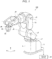
FIG. 1 , arobot system 100 according to a first embodiment includes, for example, arobot 1 and acontrol device 40. Therobot 1 includes, for example, amanipulator 10 including a plurality of joints J1 to J6, abase 11 that supports themanipulator 10, anend effector 20, and aforce sensor 30. As therobot 1, for example, a general-purpose robot capable of performing various kinds of work according to programs generated by a not-shown teaching device is adopted. - The
manipulator 10 is, for example, a robotic arm including seven links coupled to one another by the six joints J1 to J6 to thereby move at six degrees of freedom. In an example shown inFIG. 1 , themanipulator 10 is a six-axis arm including the six joints J1 to J6, which are respectively rotary joints. Themanipulator 10 may include any joint structure if the joint structure includes a plurality of joints. For example, the number of joints is three or more. Thebase 11 supports, in the joint J1, a first link of themanipulator 10, that is, one link closest to thebase 11 side. - The
end effector 20 is a tool such as a screwdriver, a gripper, or a grinder. Theend effector 20 performs various kinds of work such as screwing, gripping, polishing. Theend effector 20 is attached to a mechanical interface at the distal end of themanipulator 10 via theforce sensor 30. Themanipulator 10 is controlled to be driven by thecontrol device 40 to thereby determine a position and a posture, that is, a pose of theend effector 20. - The
force sensor 30 detects an external force acting on a tool center point (TCP), which is a reference of the position of theend effector 20, for example, via theend effector 20. Specifically, theforce sensor 30 outputs a signal indicating the external force to thecontrol device 40, whereby force on three detection axes and torques around the three detection axes acting on the TCP are detected as the external force in thecontrol device 40. The three detection axes form, for example, a world coordinate system defined by an x axis, a y axis, and a z axis orthogonal to one another. - As shown in
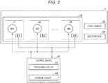
FIG. 2 , the plurality of joints J1 to J6 include a plurality of motors M1 to M6 and a plurality of encoders E1 to E6. The motors M1 to M6 are driven by control by thecontrol device 40 and respectively drive the joints J1 to J6. The encoders E1 to E6 detect rotation angles of the motors M1 to M6 and output the rotation angles to thecontrol device 40. - For example, a first joint J1 disposed closest to the
base 11 among the joints J1 to J6 includes a first motor M1 and a first encoder E1 that detects a rotation angle of the first motor M1. A rotation axis of the first joint J1 extends along the z axis in the world coordinate system. A second joint J2 second from thebase 11 among the joints J1 to J6 includes a second motor M2 and a second encoder E2 that detects a rotation angle of the second motor M2. A rotation axis of the second joint J2 extends along an x-y plane in the world coordinate system. Similarly, a distal end joint J6 disposed closest to the distal end side of themanipulator 10 among the joints J1 to J6 includes a distal end motor M6 and a distal end encoder E6 that detects a rotation angle of the distal end motor M6. - The
control device 40 includes aprocessing circuit 41 and astorage circuit 42 configuring a computer system. Theprocessing circuit 41 executes, for example, a control program stored in thestorage circuit 42 to thereby realize functions described in the embodiment. As a circuit configuring at least a part of theprocessing circuit 41, various logical operation circuits such as a central processing unit (CPU), a digital signal processor (DSP), a programmable logic device (PLD), and an application specific integrated circuit (ASIC) can be adopted. - The
storage circuit 42 is a computer-readable storage medium that stores a control program indicating a series of processing necessary for the operation of therobot system 100 and various data. As thestorage circuit 42, for example, a semiconductor memory can be adopted. Each of theprocessing circuit 41 and thestorage circuit 42 may be configured from integrated hardware or may be configured from a separate plurality of kinds of hardware. A part or all of components of thecontrol device 40 may be disposed on the inner side of a housing of therobot 1. - The
control device 40 executes, according to the control program, position control for driving the motors M1 to M6 to move the TCP to a pose, which is a target value. Thecontrol device 40 detects the pose of the TCP in the world coordinate system based on rotation angles acquired from the encoders E1 to E6. Thecontrol device 40 executes, according to the control program, based on information indicating an external force input from theforce sensor 30, force control for correcting the target value of the TCP such that the external force acting on the TCP coincides with a target force. Thecontrol device 40 can control, according to the control program, driving of a motor included in theend effector 20. - As shown in
FIG. 3 , in an example 1, a type of the first motor M1, the second motor M2, and a third motor M3 is an axial gap type. A type of a fourth motor M4, a fifth motor M5, and the distal end motor M6 is a radial gap type. In the plurality of motors M1 to M6 from the first motor M1 to the distal end motor M6, when viewed in order from the base 11 side to the distal end side, the number of change points where the axial gap type changes to the radial gap type is one. That is, in the motors M1 to M6, the number of pairs of motors of the axial gap type and the radial gap type adjacent to each other like a pair of the third motor M3 and the fourth motor M4 is one. In other words, all of the axial gap type motors included in themanipulator 10 are provided further on the base 11 side of themanipulator 10 than the radial gap type motors. - As shown in
FIG. 4 , an axial gap type motor Ma includes ashaft 50, anarmature 51,field magnets 52 opposed to thearmature 51, and back yokes 53 disposed on sides of thefield magnets 52 opposite to thearmature 51. Gaps between thearmature 51 and thefield magnets 52 are provided in a direction along theshaft 50. In an example shown inFIG. 4 , a pair offield magnets 52 are disposed to sandwich thearmature 51. However, the number of thefield magnets 52 may be one. For example, the motor Ma includes thearmature 51 as a rotor and includes thefield magnet 52 as a stator. The motor Ma may include thearmature 51 as the stator and include thefield magnet 52 as the rotor. Theshaft 50 can be equivalent to a rotating shaft of the rotor. - As shown in
FIG. 5 , thearmature 51 generally has a disk shape. Thearmature 51 includes a plurality ofcores 54 and a plurality ofcoils 55. Each of thecores 54 generally has a triangular prism shape having height along theshaft 50. Thecore 54 is made of, for example, an amorphous magnetic body and configured from a plurality of plates stacked in the radial direction of theshaft 50. The plurality ofcores 54 are supported by, for example, bobbins, whereby a positional relation among the plurality ofcores 54 is fixed. Each of thecoils 55 is made of a winding wire wound on the side surface of thecore 54. The number of pairs of thecores 54 and thecoils 55 is, for example, eighteen. The plurality ofcores 54 and the plurality ofcoils 55 are arrayed at equal intervals along the circumference of a circle centering on theshaft 50 to have eighteen times of rotational symmetry concerning theshaft 50. - As shown in
FIG. 6 , thefield magnet 52 generally has a disk shape. Thefield magnet 52 includes a plurality ofmagnetic poles 58 arrayed along the circumference of the circle centering on theshaft 50. The plurality ofmagnetic poles 58 have magnetization directions cyclically different in an array direction. The plurality ofmagnetic poles 58 include, per cycle, a pair of main magnetic poles including a first main magnetic pole magnetized in a first direction along theshaft 50 and a second main magnetic pole magnetized in a second direction opposite to the first direction. - As shown in
FIG. 7 , when the number of themagnetic poles 58 per half cycle in the array direction is represented as I, afield magnet 52a with I=1 includes twomagnetic poles 58a, that is, the pair of main magnetic poles including the first main magnetic pole and the second main magnetic pole per cycle. Afield magnet 52b with I=2 includes fourmagnetic poles 58b, that is, a pair of main magnetic poles and a pair of sub-magnetic poles per cycle. Themagnetic pole 58b has a magnetization direction different from a magnetization direction of an adjacentmagnetic pole 58b by 90° when viewed from the radial direction of theshaft 50. Each of the plurality ofmagnetic poles 58b has a magnetization direction that changes to rotate 90° at a time with the radial direction of theshaft 50 as an axis in order in the array direction. - A
field magnet 52c with I=3 includes sixmagnetic poles 58c, that is, a pair of main magnetic poles and four sub-magnetic poles per cycle. Themagnetic pole 58c has a magnetization direction different from a magnetization direction of an adjacentmagnetic pole 58c by 60° when viewed from the radial direction of theshaft 50. Each of the plurality ofmagnetic poles 58c has a magnetization direction that changes to rotate 60° at a time with the radial direction of theshaft 50 as an axis in order in the array direction. Afield magnet 52d with I=4 includes eightmagnetic poles 58d, that is, a pair of main magnetic poles and six sub-magnetic poles per cycle. Themagnetic pole 58d has a magnetization direction different from an adjacentmagnetic pole 58d by 45° when viewed from the radial direction of theshaft 50. Each of the plurality ofmagnetic poles 58d has a magnetization direction that changes to rotate 45° at a time with the radial direction of theshaft 50 as an axis in order in the array direction. - The
field magnet 52 with I≥2 such asfield magnets armature 51 is disposed on a strong magnetic field side of the Halbach array. On the other hand, theback yoke 53 is disposed on a weak magnetic field side of the Halbach array. When thefield magnet 52 forms the Halbach array, the motor Ma can increase magnetic flux density on the surface on thearmature 51 side. Therefore, a torque constant can be improved. In particular, when I is 3 or 4, a change in the magnetic flux density in the array direction can be smoothed. The torque constant can be further improved. - As shown in
FIG. 8 , a radial gap type motor Mr includes ashaft 60, anarmature 61,field magnets 62 opposed to thearmature 61, and back yokes 63 disposed on sides of thefield magnets 62 opposite to thearmature 61. Gaps between thearmature 61 and thefield magnets 62 are provided in the radial direction of theshaft 60. In an example shown inFIG. 8 , thearmature 61 generally having a columnar shape is disposed on the inner side of thefield magnet 62 having a cylindrical shape. However, the motor Mr may have topology in which thearmature 61 is disposed on the outer side of thefield magnet 62. For example, the motor Mr includes thearmature 61 as a rotor and includes thefield magnet 62 as a stator. The motor Mr may include thearmature 61 as the stator and include thefield magnet 62 as the rotor. Theshaft 60 can be equivalent to a rotating shaft of the rotor. - As shown in
FIG. 9 , thearmature 61 includes acore 64 and a plurality ofcoils 67. Thecore 64 includes acylindrical yoke section 65 and a plurality ofrib sections 66 projecting to the outer side from the side surface of theyoke section 65. Thecore 64 is made of, for example, an amorphous magnetic body. Each of the plurality ofrib sections 66 extends along theshaft 60. Each of the plurality ofrib sections 66 is configured from, for example, a plurality of plates stacked in a direction along theshaft 60. Each of thecoils 67 is made of a winding wire wound on therib section 66. The number of pairs of therib sections 66 and thecoils 67 is, for example, eighteen. The plurality ofrib sections 66 and the plurality ofcoils 67 are disposed at equal intervals along the circumference of a circle centering on theshaft 60 to have eighteen times of rotational symmetry concerning theshaft 60. - The
field magnet 62 includes a plurality ofmagnetic poles 68 arrayed along the circumference of the circle centering on theshaft 60. The plurality ofmagnetic poles 68 have magnetization directions cyclically different in an array direction. The plurality ofmagnetic poles 68 include, per cycle, a pair of main magnetic poles, that is, a first main magnetic pole magnetized in the radial direction of theshaft 60 and a second main magnetic pole magnetized in a direction opposite to the magnetization direction of the first main magnetic pole. When the number of themagnetic poles 68 per half cycle in the array direction is represented as I, as shown inFIG. 10 , afield magnet 62a with I=1 includes twomagnetic poles 68a, that is, a pair of main magnet poles including the first main magnetic pole and the second main magnetic pole per cycle. - As shown in
FIG. 11 , afield magnet 62b with I=2 includes fourmagnetic poles 68b, that is, a pair of main magnetic poles and a pair of sub-magnetic poles per cycle. When the center axis of theshaft 60 is represented as an axis P, themagnetic pole 68b has a magnetization direction different from a magnetization direction of an adjacentmagnetic pole 68b by 90° based on the axis P when viewed from a direction along the axis P. That is, each of the plurality ofmagnetic poles 68b has a magnetization direction that changes to rotate 90° at a time in the array direction in order based on the axis P. - As shown in
FIG. 12 , afield magnet 62c with I=3 includes sixmagnetic poles 68c, that is, a pair of main magnetic poles and four sub-magnetic poles per cycle. Themagnetic pole 68c has a magnetization direction different from a magnetization direction of an adjacentmagnetic pole 68c by 60° based on the axis P when viewed from the direction along the axis P. That is, each of the plurality ofmagnetic poles 68c has a magnetization direction that changes to rotate 60° at a time in the array direction in order based on the axis P. - As shown in
FIG. 13 , afield magnet 62d with I=4 includes eightmagnetic poles 68d, that is, a pair of main magnetic poles and six sub-magnetic poles per cycle. Themagnetic pole 68d has a magnetization direction different from a magnetization direction of an adjacentmagnetic pole 68d by 45° based on the axis P when viewed from the direction along the axis P. That is, each of the plurality ofmagnetic poles 68d has a magnetization direction that changes to rotate 45° at a time in the array direction in order based on the axis P. - The
field magnet 62 with I≥2 such asfield magnets armature 61 is disposed on a strong magnetic field side of the Halbach array. On the other hand, theback yoke 63 is disposed on a weak magnetic field side of the Halbach array. When thefield magnet 62 forms the Halbach array, the motor Mr can increase magnetic flux density on the surface on thearmature 61 side. Therefore, a torque constant can be improved. In particular, when I is 3 or 4, a change in the magnetic flux density in the array direction can be smoothed. The torque constant can be further improved. - In the example 1 shown in
FIG. 3 , each of the first motor M1, the second motor M2, and third motor M3 is equivalent to the axial gap type motor Ma. The third motor M3 may be the radial gap type motor Mr. When increasing torque, the axial gap type motor Ma can prevent an increase in a dimension in a rotation axis direction compared with the radial gap type. Accordingly, when the first motor M1 relatively requiring torque because the first motor M1 is disposed closest to the base 11 side in themanipulator 10 is the axial gap type, it is possible to prevent the height of a first link of thebase 11 and themanipulator 10 from increasing. - Each of the fourth motor M4, the fifth motor M5, and the distal end motor M6 is equivalent to the radial gap type motor Mr. When increasing torque, the radial gap type motor Mr can prevent an increase in a dimension in the radial direction of a rotation axis compared with the axial gap type. Accordingly, when the distal end motor M6 relatively not requiring torque because the distal end motor M6 is disposed closest to the distal end side of the
manipulator 10 is the radial gap type, it is possible to prevent a dimension of a link coupled to the distal end joint J6 from increasing in the radial direction of the distal end motor M6. - A field magnet of each of the first motor M1 to the distal end motor M6 forms a Halbach array. That is, the number of magnetic poles I per half cycle in the Halbach array is two or more. Consequently, since magnetic flux density on a strong magnetic field side of the Halbach array can be increased, a torque constant can be improved. In particular, when I is 3 or 4, a change in magnetic flux density in the array direction can be smoothed. The torque constant can be further improved.
- The first motor M1 drives the first joint J1 with direct drive. The third motor M3 drives the third joint J3 with the direct drive. Alternatively, each of all of the first motor M1, the second motor M2, and the third motor M3 of the axial gap type may drive any one of the joints J1 to J3 corresponding thereto with the direct drive. In this way, at least any one of the motors M1 to M6 may drive any one of the joints J1 to J6 corresponding thereto with the direct drive. Consequently, a speed reducer can be omitted. Low-speed torque can be improved. A reduction in weight and a reduction in manufacturing cost can be realized.
- When the third motor M3 is the axial gap type motor Ma, the third motor M3 may include the
armature 51 having a coreless structure not including thecore 54. Similarly, when the third motor M3 is the radial gap type motor Mr, the third motor M3 may include thearmature 61 having the coreless structure not including thecore 64. Similarly, the third motor M3 may not include theback yoke 53 or theback yoke 63. Consequently, a reduction in the weight of themanipulator 10 can be realized. - In particular, the heights of the first joint J1 and the second joint J2 based on the
base 11 are fixed. The heights of the joints J3 to J6 further on the distal end side than the second joint J2 based on the base 11 can change. Accordingly, at least any one of the motors M3 to M6 further on the distal end side than the second motor M2 having the coreless structure can reduce a loss and heat generation due to an eddy current and further contribute to improvement of the motion performance of themanipulator 10 through a reduction in weight. When the motors M1 to M6 include field magnets forming a Halbach array, theback yoke 53 or theback yoke 63 on the weak magnetic field side can be omitted. Consequently, the motion performance of themanipulator 10 can be further improved. - In an example 2, only the type of the first motor M1 is the axial gap type. The type of the other motors M2 to M6 is the radial gap type. The other components not explained in the example 2 may be the same as or may be different from the components in the example 1.
- In an example 3, the type of the first motor M1, the third motor M3, and the fifth motor M5 is the axial gap type and the type of the second motor M2, the fourth motor M4, and the distal end motor M6 is the radial gap type. In this way, in the motors M1 to M6, the number of pairs of an axial gap type motor and a radial gap type motor adjacent to each other may be two or more. The other components, action, and effects not explained in the examples 2 and 3 are the same as those in the example 1.
- In the
robot system 100 according to the first embodiment, the type of the first motor M1 of the first joint J1 is the axial gap type and the type of the distal end motor M6 of the distal end joint J6 is the radial gap type. Since the first motor M1 relatively requiring torque is the axial gap type, it is possible to prevent the height of the first link of thebase 11 and themanipulator 10 from increasing. Since the distal end motor M6 relatively not requiring torque is the radial gap type, it is possible to prevent the dimension of the link coupled to the distal end joint J6 from increasing in the radial direction of the distal end motor M6. Consequently, a weight balance and volume efficiency of themanipulator 10 are improved. Speed, motion performance such as speed, acceleration, jerk, and a movement range of themanipulator 10 can be improved. - As shown in
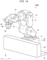
FIG. 14 , arobot system 100A according to a second embodiment includes, for example, arobot 1A, amobile stand 12 that moves therobot 1A, and a not-shown control device. The other components, action, and effects not explained in the second embodiment are the same as those in the first embodiment. Therefore, redundant explanation of the components, the action, and the effects is omitted. - The
robot 1A includes themanipulator 10 including a plurality of joints J1 to J6, abase 11A that supports themanipulator 10, theend effector 20, and theforce sensor 30. Themobile stand 12 moves thebase 11A along the x axis in the world coordinate system with an axial gap type motor M0 to thereby move therobot 1A. Themobile stand 12 may move therobot 1A along a curve. - As shown in
FIG. 15 , arobot system 100B according to a third embodiment is different from the first and second embodiments in that, for example, therobot system 100B includes arobot 1B, which is a SCARA robot. The other components, action, and effects not explained in the third embodiment are the same as those in the first and second embodiments. Therefore, redundant explanation of the components, the action, and the effects is omitted. - The
robot 1B includes amanipulator 10B including a plurality of joints J1 to J4, a base 11B that supports themanipulator 10B, and theend effector 20. Like therobot 1 according to the first embodiment, therobot 1B can include a not-shown force sensor that detects an external force acting on theend effector 20. Further, therobot 1B includes thecontrol device 40 housed on the inner side of the base 11B. - The
manipulator 10B includes afirst link 101 and asecond link 102. Thefirst link 101 is coupled to the base 11B via the first joint J1 disposed closest to the base 11B side. The first joint J1 is driven by the first motor M1. The second joint J2 from the base 11B among the joints J1 to J4 is driven by the second motor M2. Rotation axes of the first joint J1 and the second joint J2 extend along the z axis in the world coordinate system. Rotation angles of the first motor M1 and the second motor M2 are detected by the first encoder E1 and the second encoder E2. - The
manipulator 10B includes aball screw spline 21 provided in thesecond link 102. Theball screw spline 21 includes ascrew spline shaft 22, anut 23, and anouter cylinder 24. Thescrew spline shaft 22 includes a spiral screw groove and a spline groove extending along the axial direction of thescrew spline shaft 22. Thenut 23 and theouter cylinder 24 respectively include through-holes into which thescrew spline shaft 22 is inserted. The center position of thenut 23 and theouter cylinder 24 is relatively fixed to a frame of thesecond link 102. - The third joint J3 and the fourth joint J4 disposed closest to the distal end side among the joints J1 to J4 are respectively driven by the third motor M3 and the fourth motor M4. Rotation angles of the third motor M3 and the fourth motor M4 are detected by the third encoder E3 and the fourth encoder E4.
- The third motor M3 rotates the
nut 23 via a speed reducer. Thescrew spline shaft 22 moves straight along the z axis according to the rotation of thenut 23. In this way, thescrew spline shaft 22 and thenut 23 configuring the ball screw cause theend effector 20 to move straight with respect to thesecond link 102. When theouter cylinder 24 rotates according to the rotation of the fourth motor M4, thescrew spline shaft 22 rotates together with theouter cylinder 24. Thescrew spline shaft 22 and theouter cylinder 24 configuring the ball spline cause theend effector 20 to rotate with respect to thesecond link 102. - For example, a type of the first motor M1 is the axial gap type. A type of at least any one distal end motor of the third motor M3 and the fourth motor M4 is the radial gap type. A type of the second motor M2 is the axial gap type or the radial gap type. Consequently, when viewed in order from the base 11B side to the distal end side, the number of change points where the axial gap type changes to the radial gap type is one.
- The embodiments are explained above. However, the present disclosure is not limited to the disclosures of the embodiments. The components of the sections may be replaced with any components having the same functions. Any components in the embodiments may be omitted or added within the technical scope of the present disclosure. In this way, various alternative embodiments will be made clear for those skilled in the art from these disclosures.
- For example, the number of manipulators and the number of end effectors included in a robot such as the
robots robot systems - Besides, it goes without saying that the present disclosure includes various embodiments not explained above such as a configuration in which the components explained above are applied to one another. The technical scope of the present disclosure can be decided only by reasonable matters to define the inventions according to the appended claims from the above explanation.
Claims (7)
- A robot comprising:a manipulator including a plurality of joints; anda base configured to support the manipulator, whereina joint closest to the base side among the plurality of joints includes a first motor of an axial gap type, anda joint closest to a distal end side of the manipulator among the plurality of joints includes a distal end motor of a radial gap type.
- The robot according to claim 1, wherein
a number of the plurality of joints is three or more, and
a second joint from the base among the plurality of joints of the manipulator includes a second motor of the axial gap type. - The robot according to claim 1, wherein all motors of the axial gap type included in the manipulator are provided further on the base side of the manipulator than motors of the radial gap type.
- The robot according to claim 1, wherein a field magnet of the first motor forms a Halbach array.
- The robot according to claim 4, wherein a number of magnetic poles per half cycle of the Halbach array is three or four.
- The robot according to claim 1, wherein the first motor is driven by direct drive.
- A robot system comprising:the robot according to claim 1; anda mobile stand configured to move the robot with an axial gap type motor.
Applications Claiming Priority (1)
| Application Number | Priority Date | Filing Date | Title |
|---|---|---|---|
| JP2020055574A JP2021158751A (en) | 2020-03-26 | 2020-03-26 | Robot and robot system |
Publications (1)
| Publication Number | Publication Date |
|---|---|
| EP3892425A1 true EP3892425A1 (en) | 2021-10-13 |
Family
ID=75143428
Family Applications (1)
| Application Number | Title | Priority Date | Filing Date |
|---|---|---|---|
| EP21163024.9A Pending EP3892425A1 (en) | 2020-03-26 | 2021-03-17 | Robot and robot system |
Country Status (4)
| Country | Link |
|---|---|
| US (1) | US20210299859A1 (en) |
| EP (1) | EP3892425A1 (en) |
| JP (1) | JP2021158751A (en) |
| CN (1) | CN113442162B (en) |
Families Citing this family (3)
| Publication number | Priority date | Publication date | Assignee | Title |
|---|---|---|---|---|
| WO2020237721A1 (en) * | 2019-05-30 | 2020-12-03 | 苏州大学 | Planar articulated robot and inner rotor articulation apparatus |
| JP2023049172A (en) | 2021-09-29 | 2023-04-10 | 光洋シーリングテクノ株式会社 | Rubber composition for seal, and sealing member |
| DE102022106623A1 (en) | 2022-03-22 | 2023-09-28 | Schaeffler Technologies AG & Co. KG | Electric axial flux machine, drive module, method for producing an electric axial flux machine |
Citations (7)
| Publication number | Priority date | Publication date | Assignee | Title |
|---|---|---|---|---|
| US5270600A (en) * | 1991-05-08 | 1993-12-14 | Koyo Seiko Co. Ltd. | Magnetic drive device |
| JP2005262340A (en) | 2004-03-16 | 2005-09-29 | Fanuc Ltd | Industrial robot |
| JP2012120358A (en) * | 2010-12-02 | 2012-06-21 | Seiko Epson Corp | Coreless electromechanical device |
| US20130069450A1 (en) * | 2011-09-16 | 2013-03-21 | Persimmon Technologies, Corp. | Robot Drive With Passive Rotor |
| CN105305749A (en) * | 2015-10-23 | 2016-02-03 | 南京航空航天大学 | Axial flux motor of stator iron-core-free Halbach permanent magnet array |
| CN209140882U (en) * | 2018-10-23 | 2019-07-23 | 广东博智林机器人有限公司 | A kind of omni-directional moving mechanism and hoisting machine people's system |
| JP2020055574A (en) | 2018-09-28 | 2020-04-09 | 大日本印刷株式会社 | Card packaging container |
Family Cites Families (19)
| Publication number | Priority date | Publication date | Assignee | Title |
|---|---|---|---|---|
| JP2016190297A (en) * | 2015-03-31 | 2016-11-10 | セイコーエプソン株式会社 | Robot system |
| US7768157B2 (en) * | 2006-10-30 | 2010-08-03 | Seiko Epson Corporation | Brushless motor |
| US20110291532A1 (en) * | 2010-05-26 | 2011-12-01 | Seiko Epson Corporation | Coreless electromechanical device |
| JP2012147541A (en) * | 2011-01-11 | 2012-08-02 | Seiko Epson Corp | Electromechanical device, and actuator, motor, robot, and robot hand using the same |
| JP2012200045A (en) * | 2011-03-18 | 2012-10-18 | Seiko Epson Corp | Electric motor, robot and brake device |
| JP2012253922A (en) * | 2011-06-03 | 2012-12-20 | Seiko Epson Corp | Coreless electromechanical device, mobile object, robot, and coreless-electromechanical-device producing method |
| JP2012257413A (en) * | 2011-06-10 | 2012-12-27 | Seiko Epson Corp | Electromechanical device, robot, movable body, and manufacturing method of electromechanical device |
| JP2013058658A (en) * | 2011-09-09 | 2013-03-28 | Seiko Epson Corp | Electromagnetic coil, coreless electric machine device, moving body, robot, and manufacturing method of electromagnetic coil |
| JP2013062969A (en) * | 2011-09-14 | 2013-04-04 | Seiko Epson Corp | Coil back yoke, coreless electromechanical device, mobile object, robot, and method for manufacturing coil back yoke |
| JP2013078167A (en) * | 2011-09-29 | 2013-04-25 | Seiko Epson Corp | Coreless electromechanical device, moving body, robot and manufacturing method of coreless electromechanical device |
| US10807248B2 (en) * | 2014-01-31 | 2020-10-20 | Systems, Machines, Automation Components Corporation | Direct drive brushless motor for robotic finger |
| KR101688876B1 (en) * | 2014-07-09 | 2016-12-22 | 한국해양과학기술원 | Structure of magnetic coupling for obtaining high torque transmission performance |
| JP2018529302A (en) * | 2015-08-11 | 2018-10-04 | ジェネシス ロボティクス エルエルピー | Electric machine |
| JP2017159425A (en) * | 2016-03-11 | 2017-09-14 | セイコーエプソン株式会社 | robot |
| WO2017197497A1 (en) * | 2016-04-13 | 2017-11-23 | Genesis Robotics Llp | Electric machine comprising axial thrust bearings |
| WO2018010006A1 (en) * | 2016-07-13 | 2018-01-18 | Crosswing Inc. | Mobile robot |
| WO2018149499A1 (en) * | 2017-02-16 | 2018-08-23 | Halodi Robotics A/S | Human-like direct drive robot |
| JP6676014B2 (en) * | 2017-08-07 | 2020-04-08 | 三菱重工業株式会社 | Axial gap motor and rotor manufacturing method |
| JP2019155514A (en) * | 2018-03-09 | 2019-09-19 | セイコーエプソン株式会社 | Robot and robot system |
-
2020
- 2020-03-26 JP JP2020055574A patent/JP2021158751A/en not_active Withdrawn
-
2021
- 2021-03-17 EP EP21163024.9A patent/EP3892425A1/en active Pending
- 2021-03-25 US US17/211,909 patent/US20210299859A1/en not_active Abandoned
- 2021-03-25 CN CN202110320759.8A patent/CN113442162B/en active Active
Patent Citations (7)
| Publication number | Priority date | Publication date | Assignee | Title |
|---|---|---|---|---|
| US5270600A (en) * | 1991-05-08 | 1993-12-14 | Koyo Seiko Co. Ltd. | Magnetic drive device |
| JP2005262340A (en) | 2004-03-16 | 2005-09-29 | Fanuc Ltd | Industrial robot |
| JP2012120358A (en) * | 2010-12-02 | 2012-06-21 | Seiko Epson Corp | Coreless electromechanical device |
| US20130069450A1 (en) * | 2011-09-16 | 2013-03-21 | Persimmon Technologies, Corp. | Robot Drive With Passive Rotor |
| CN105305749A (en) * | 2015-10-23 | 2016-02-03 | 南京航空航天大学 | Axial flux motor of stator iron-core-free Halbach permanent magnet array |
| JP2020055574A (en) | 2018-09-28 | 2020-04-09 | 大日本印刷株式会社 | Card packaging container |
| CN209140882U (en) * | 2018-10-23 | 2019-07-23 | 广东博智林机器人有限公司 | A kind of omni-directional moving mechanism and hoisting machine people's system |
Also Published As
| Publication number | Publication date |
|---|---|
| JP2021158751A (en) | 2021-10-07 |
| CN113442162B (en) | 2024-01-16 |
| US20210299859A1 (en) | 2021-09-30 |
| CN113442162A (en) | 2021-09-28 |
Similar Documents
| Publication | Publication Date | Title |
|---|---|---|
| EP3892425A1 (en) | Robot and robot system | |
| US9785138B2 (en) | Robot and robot controller | |
| EP1084802B1 (en) | Four-degree-of-freedom parallel robot | |
| US20160101526A1 (en) | Robot and robot joint mechanism | |
| JP2005144627A (en) | Link operating device | |
| JP2017159425A (en) | robot | |
| JP2003070284A (en) | Servo actuator and its position detector | |
| US20220131452A1 (en) | Motor And Robot | |
| JP7336215B2 (en) | Robot system, control method, article manufacturing method, program, and recording medium | |
| Harada | Novel Schönflies motion parallel robot driven by differential mechanism | |
| US11476742B1 (en) | Multi-degree-of-freedom spherical motor | |
| JP2022107268A (en) | robot | |
| JP2023169981A (en) | Robot and robot system | |
| US20220352799A1 (en) | Rotary motor and robot arm | |
| Bianchini et al. | Arc linear motors for direct drive robots: Galileo sphere | |
| WO2022062192A1 (en) | Electric motor, power device, unmanned aerial vehicle and gimbal | |
| KR101766576B1 (en) | Driving apparatus having multi-degrees of freedom | |
| CN109968007B (en) | Macro-micro manipulator spiral part assembling device based on active-passive cooperative compliance | |
| US20210069896A1 (en) | 6-Dof Parallel Robot With A Double-Gyroscopic Component | |
| Ang Jr et al. | Passive compliance from robot limbs and its usefulness in robotic automation | |
| JPH11287303A (en) | Parallel link mechanism | |
| KR100239370B1 (en) | Robot joint using supersonic wave motor | |
| JP2019155514A (en) | Robot and robot system | |
| CN217572894U (en) | Seven-degree-of-freedom mechanical arm structure | |
| Yano | Proposal of a truncatedoctahedron-dodecahedron based spherical stepping motor |
Legal Events
| Date | Code | Title | Description |
|---|---|---|---|
| PUAI | Public reference made under article 153(3) epc to a published international application that has entered the european phase |
Free format text: ORIGINAL CODE: 0009012 |
|
| STAA | Information on the status of an ep patent application or granted ep patent |
Free format text: STATUS: THE APPLICATION HAS BEEN PUBLISHED |
|
| AK | Designated contracting states |
Kind code of ref document: A1 Designated state(s): AL AT BE BG CH CY CZ DE DK EE ES FI FR GB GR HR HU IE IS IT LI LT LU LV MC MK MT NL NO PL PT RO RS SE SI SK SM TR |
|
| STAA | Information on the status of an ep patent application or granted ep patent |
Free format text: STATUS: REQUEST FOR EXAMINATION WAS MADE |
|
| 17P | Request for examination filed |
Effective date: 20220331 |
|
| RBV | Designated contracting states (corrected) |
Designated state(s): AL AT BE BG CH CY CZ DE DK EE ES FI FR GB GR HR HU IE IS IT LI LT LU LV MC MK MT NL NO PL PT RO RS SE SI SK SM TR |
|
| STAA | Information on the status of an ep patent application or granted ep patent |
Free format text: STATUS: EXAMINATION IS IN PROGRESS |
|
| 17Q | First examination report despatched |
Effective date: 20240312 |