EP3892417A1 - Jig for tack welding of battery cell electrode lead - Google Patents
Jig for tack welding of battery cell electrode lead Download PDFInfo
- Publication number
- EP3892417A1 EP3892417A1 EP20738817.4A EP20738817A EP3892417A1 EP 3892417 A1 EP3892417 A1 EP 3892417A1 EP 20738817 A EP20738817 A EP 20738817A EP 3892417 A1 EP3892417 A1 EP 3892417A1
- Authority
- EP
- European Patent Office
- Prior art keywords
- battery cells
- tack welding
- electrode lead
- jig
- guide member
- Prior art date
- Legal status (The legal status is an assumption and is not a legal conclusion. Google has not performed a legal analysis and makes no representation as to the accuracy of the status listed.)
- Granted
Links
Images




Classifications
-
- B—PERFORMING OPERATIONS; TRANSPORTING
- B23—MACHINE TOOLS; METAL-WORKING NOT OTHERWISE PROVIDED FOR
- B23K—SOLDERING OR UNSOLDERING; WELDING; CLADDING OR PLATING BY SOLDERING OR WELDING; CUTTING BY APPLYING HEAT LOCALLY, e.g. FLAME CUTTING; WORKING BY LASER BEAM
- B23K37/00—Auxiliary devices or processes, not specially adapted for a procedure covered by only one of the other main groups of this subclass
- B23K37/04—Auxiliary devices or processes, not specially adapted for a procedure covered by only one of the other main groups of this subclass for holding or positioning work
- B23K37/0426—Fixtures for other work
- B23K37/0435—Clamps
- B23K37/0443—Jigs
-
- B—PERFORMING OPERATIONS; TRANSPORTING
- B23—MACHINE TOOLS; METAL-WORKING NOT OTHERWISE PROVIDED FOR
- B23K—SOLDERING OR UNSOLDERING; WELDING; CLADDING OR PLATING BY SOLDERING OR WELDING; CUTTING BY APPLYING HEAT LOCALLY, e.g. FLAME CUTTING; WORKING BY LASER BEAM
- B23K20/00—Non-electric welding by applying impact or other pressure, with or without the application of heat, e.g. cladding or plating
- B23K20/10—Non-electric welding by applying impact or other pressure, with or without the application of heat, e.g. cladding or plating making use of vibrations, e.g. ultrasonic welding
-
- B—PERFORMING OPERATIONS; TRANSPORTING
- B23—MACHINE TOOLS; METAL-WORKING NOT OTHERWISE PROVIDED FOR
- B23K—SOLDERING OR UNSOLDERING; WELDING; CLADDING OR PLATING BY SOLDERING OR WELDING; CUTTING BY APPLYING HEAT LOCALLY, e.g. FLAME CUTTING; WORKING BY LASER BEAM
- B23K26/00—Working by laser beam, e.g. welding, cutting or boring
- B23K26/70—Auxiliary operations or equipment
- B23K26/702—Auxiliary equipment
-
- H—ELECTRICITY
- H01—ELECTRIC ELEMENTS
- H01M—PROCESSES OR MEANS, e.g. BATTERIES, FOR THE DIRECT CONVERSION OF CHEMICAL ENERGY INTO ELECTRICAL ENERGY
- H01M50/00—Constructional details or processes of manufacture of the non-active parts of electrochemical cells other than fuel cells, e.g. hybrid cells
- H01M50/50—Current conducting connections for cells or batteries
- H01M50/531—Electrode connections inside a battery casing
- H01M50/536—Electrode connections inside a battery casing characterised by the method of fixing the leads to the electrodes, e.g. by welding
-
- B—PERFORMING OPERATIONS; TRANSPORTING
- B23—MACHINE TOOLS; METAL-WORKING NOT OTHERWISE PROVIDED FOR
- B23K—SOLDERING OR UNSOLDERING; WELDING; CLADDING OR PLATING BY SOLDERING OR WELDING; CUTTING BY APPLYING HEAT LOCALLY, e.g. FLAME CUTTING; WORKING BY LASER BEAM
- B23K2101/00—Articles made by soldering, welding or cutting
- B23K2101/36—Electric or electronic devices
- B23K2101/38—Conductors
-
- B—PERFORMING OPERATIONS; TRANSPORTING
- B23—MACHINE TOOLS; METAL-WORKING NOT OTHERWISE PROVIDED FOR
- B23K—SOLDERING OR UNSOLDERING; WELDING; CLADDING OR PLATING BY SOLDERING OR WELDING; CUTTING BY APPLYING HEAT LOCALLY, e.g. FLAME CUTTING; WORKING BY LASER BEAM
- B23K26/00—Working by laser beam, e.g. welding, cutting or boring
- B23K26/20—Bonding
- B23K26/21—Bonding by welding
- B23K26/22—Spot welding
-
- H—ELECTRICITY
- H01—ELECTRIC ELEMENTS
- H01M—PROCESSES OR MEANS, e.g. BATTERIES, FOR THE DIRECT CONVERSION OF CHEMICAL ENERGY INTO ELECTRICAL ENERGY
- H01M50/00—Constructional details or processes of manufacture of the non-active parts of electrochemical cells other than fuel cells, e.g. hybrid cells
- H01M50/50—Current conducting connections for cells or batteries
- H01M50/502—Interconnectors for connecting terminals of adjacent batteries; Interconnectors for connecting cells outside a battery casing
- H01M50/514—Methods for interconnecting adjacent batteries or cells
- H01M50/516—Methods for interconnecting adjacent batteries or cells by welding, soldering or brazing
-
- Y—GENERAL TAGGING OF NEW TECHNOLOGICAL DEVELOPMENTS; GENERAL TAGGING OF CROSS-SECTIONAL TECHNOLOGIES SPANNING OVER SEVERAL SECTIONS OF THE IPC; TECHNICAL SUBJECTS COVERED BY FORMER USPC CROSS-REFERENCE ART COLLECTIONS [XRACs] AND DIGESTS
- Y02—TECHNOLOGIES OR APPLICATIONS FOR MITIGATION OR ADAPTATION AGAINST CLIMATE CHANGE
- Y02E—REDUCTION OF GREENHOUSE GAS [GHG] EMISSIONS, RELATED TO ENERGY GENERATION, TRANSMISSION OR DISTRIBUTION
- Y02E60/00—Enabling technologies; Technologies with a potential or indirect contribution to GHG emissions mitigation
- Y02E60/10—Energy storage using batteries
-
- Y—GENERAL TAGGING OF NEW TECHNOLOGICAL DEVELOPMENTS; GENERAL TAGGING OF CROSS-SECTIONAL TECHNOLOGIES SPANNING OVER SEVERAL SECTIONS OF THE IPC; TECHNICAL SUBJECTS COVERED BY FORMER USPC CROSS-REFERENCE ART COLLECTIONS [XRACs] AND DIGESTS
- Y02—TECHNOLOGIES OR APPLICATIONS FOR MITIGATION OR ADAPTATION AGAINST CLIMATE CHANGE
- Y02P—CLIMATE CHANGE MITIGATION TECHNOLOGIES IN THE PRODUCTION OR PROCESSING OF GOODS
- Y02P70/00—Climate change mitigation technologies in the production process for final industrial or consumer products
- Y02P70/50—Manufacturing or production processes characterised by the final manufactured product
Definitions
- the present disclosure relates to an electrode lead tack welding jig for a battery cell.
- Secondary batteries which are highly applicable to various products and exhibit superior electrical properties such as high energy density, etc. are commonly used not only in portable devices but also in electric vehicles (EVs) or hybrid electric vehicles (HEVs) driven by electrical power sources.
- EVs electric vehicles
- HEVs hybrid electric vehicles
- the secondary battery is drawing attentions as a new energy source for enhancing environment friendliness and energy efficiency in that the use of fossil fuels can be reduced greatly and no byproduct is generated during energy consumption.
- Secondary batteries widely used at present include lithium ion batteries, lithium polymer batteries, nickel cadmium batteries, nickel hydrogen batteries, nickel zinc batteries and the like.
- An operating voltage of the unit secondary battery cell namely a unit battery cell, is about 2.5V to 4.5V. Therefore, if a higher output voltage is required, a plurality of battery cells may be connected in series to configure a battery pack. In addition, depending on the charge/discharge capacity required for the battery pack, a plurality of battery cells may be connected in parallel to configure a battery pack. Thus, the number of battery cells included in the battery pack may be variously set according to the required output voltage or the demanded charge/discharge capacity.
- electrode leads of at least two battery cells are tack-welded in advance, then the tack-welded electrode leads are cut into a required length, and then the entire battery cells are stacked.
- the electrode leads of the at least two battery cells are disposed at a predetermined point for tack welding by using an electrode lead guide jig. After that, the electrode leads of the at least two battery cells are brought into close contact with each other using a separate electrode lead close contact jig, and then the electrode leads in close contact are tack-welded using an ultrasonic welding machine or a laser welding machine.
- the electrode lead guide jig and the electrode lead close contact jig are required separately, thereby increasing manufacturing costs since the jigs must be prepared separately. Moreover, since individual jigs are used separately, the overall manufacture time is also increased, thereby giving a disadvantage in terms of process efficiency.
- the present disclosure is directed to providing an electrode lead tack welding jig for a battery cell, which may improve the process efficiency by reducing manufacture cost and time.
- an electrode lead tack welding jig for a battery cell comprising: a jig body configured to support at least two battery cells; and a close contact guide unit provided to both ends of the jig body to guide electrode leads of the at least two battery cells to come into close contact when tack welding is performed to the electrode leads by laser.
- the jig body may include a first support member configured to support a lower side of the at least two battery cells; and a second support member pivotally coupled to the first support member by a hinge and configured to support an upper side of the at least two battery cells.
- the close contact guide unit may include a first guide member provided to both ends of the first support member; and a second guide member arranged to face the first guide member in a state where the electrode leads of the at least two battery cells are interposed therebetween, the second guide member being provided to both ends of the second support member.
- the close contact guide unit may include at least one knob bolt configured to bring the first guide member and the second guide member into closer contact with each other according to a manipulation of a manufacturer or the like.
- the second guide member may include a vertical plate mounted to both ends of the second support member; and a horizontal plate bent from a bottom end of the vertical plate and disposed to face the first guide member in a state where the electrode leads of the at least two battery cells are interposed therebetween.
- the horizontal plate may have a tack welding guide slit formed to partially expose the electrode leads of the at least two battery cells for tack-welding the electrode leads of the at least two battery cells by laser.
- the tack welding guide slit may be formed by a predetermined length along a longitudinal direction of the horizontal plate.
- a bottom width of the horizontal plate may correspond to a top width of the first guide member.
- the knob bolt may be provided in a pair, and the pair of knob bolts may be disposed to face each other in a state where the electrode leads of the at least two battery cells are interposed therebetween.
- the plurality of battery cells may include three battery cells mounted to the jig body, and the electrode leads of the three battery cells may be tack-welded by laser after coming into close contact with each other by the close contact guide unit.
- an electrode lead tack welding jig for a battery cell, which may improve the process efficiency by reducing manufacture cost and time.
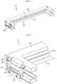
- FIG. 1 is a diagram for illustrating an electrode lead tack welding jig for a battery cell according to an embodiment of the present disclosure
- FIGS. 2 and 3 are diagrams for illustrating a rotating operation of the electrode lead tack welding jig of FIG. 1
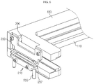
- FIGS. 4 and 5 are diagrams for illustrating main parts of the electrode lead tack welding jig of FIG. 1
- FIG. 6 is a diagram for illustrating another embodiment of a knob bolt of the electrode lead tack welding jig of FIG. 4 .
- an electrode lead tack welding jig 10 may perform tack welding to electrode leads 55 of battery cells 50 to each other.
- the battery cells 50 may be stacked in a predetermined number or more to form a battery module or a battery pack.
- the electrode leads 55 of the battery cells 50 are welded for electrical connection of the battery cells 50.
- the electrode leads 55 of the battery cells 50 may be tack-welded preferentially, and at this time, a welding process may also be applied to the electrode leads 55 of the battery cells 50.
- the electrode lead tack welding jig 10 may be applied in the welding process for the tack welding.
- the electrode lead tack welding jig 10 may be mainly applied to a so-called non-bending lead concept module that welds the electrode leads 55 of the battery cells 50 without bending.
- the non-bending lead concept module may, for example, perform tack welding to electrode leads 55 of three battery cells 50 to each other, and the electrode lead tack welding jig 10 brings three battery cells 50 into close contact with each other and then perform tack welding to the electrode leads 55 of the three battery cells 50.
- the tack welding may be performed through laser tack welding using laser.
- the electrode lead tack welding jig 10 may include a jig body 100 and a close contact guide unit 200.
- the jig body 100 serves to support at least two battery cells 50.
- the jig body 100 will be described as supporting three battery cells 50.
- the jig body 100 may include a first support member 110 and a second support member 130.
- the first support member 110 may support a lower side of the at least two battery cells 50. In this embodiment, the first support member 110 may support the lower side of three battery cells 50.
- the second support member 130 is pivotally coupled to the first support member 110 by a hinge and may support an upper side of the at least two battery cells 50. In this embodiment, the second support member 130 may support the upper side of the three battery cells 50.
- the close contact guide unit 200 is provided at both ends of the jig body 100, and may guide the electrode leads 55 to make close contact with each other when the electrode leads 55 of the at least two battery cells 50 are tack-welded by laser.
- the close contact guide unit 200 may include a first guide member 210, a second guide member 230 and a knob bolt 250.
- the first guide member 210 may be provided at both ends of the first support member 110.
- the first guide member 210 may include a tack welding guide slit 215 and a knob bolt hole 217.
- the tack welding guide slit 215 may partially expose the electrode leads 55 of the at least two battery cells 50 out of the close contact guide unit 200 for tack-welding the electrode leads 55 of the at least two battery cells 50 by laser.
- the knob bolt hole 217 may allow a knob bolt 250, explained later, to be fastened therethrough.
- the knob bolt hole 217 may guide the first guide member 210 and the second guide member 230, explained later, to make close contact with each other according to the degree of fastening with the knob bolt 250, explained later.
- the second guide member 230 is provided at both ends of the second support member 130, and may be disposed to face the first guide member 210 in a state where the electrode leads 55 of the at least two battery cells 50 are interposed therebetween.
- the second guide member 230 may include a vertical plate 231, a horizontal plate 233 and a tack welding guide slit 235.
- the vertical plate 231 may be mounted to both ends of the second support member 130.
- the horizontal plate 233 is bent from a bottom end of the vertical plate 231, and may be disposed to face the first guide member 210 in a state where the electrode leads 55 of the at least two battery cells 50 are interposed therebetween.
- the electrode leads 55 of the at least two battery cells 50 may be disposed between a bottom end of the horizontal plate 233 and a top end of the first guide member 210.
- a bottom width of the horizontal plate 233 may be formed to correspond to a top width of the first guide member 210.
- the tack welding guide slit 235 is provided to the horizontal plate 233, and the electrode leads 55 of the at least two battery cells 50 may be partially exposed out of the close contact guide unit 200 for tack-welding the electrode leads 55 of the at least two battery cells 50 by laser.
- the tack welding guide slit 235 is formed to have a predetermined length along a longitudinal direction of the horizontal plate 233, and may be provided corresponding to the tack welding guide slit 215 of the first guide member 210.
- the knob bolt 250 can may bring the first guide member 210 and the second guide member 230 into closer contact with each other according to a manipulation of a manufacturer or the like. At least one knob bolt 250, or a plurality of knob bolts 250, may be provided.
- knob bolt 250 may be provided in a pair.
- the pair of knob bolts 250 may be disposed to face each other in a state where the electrode leads 55 of the at least two battery cells 50 are interposed therebetween, and may be screwed according to the manipulation of the manufacturer or the like so that the first guide member 210 and the second guide member 230 may make closer contact with each other.
- the manipulation for screw-fastening the pair of knob bolts 250 may be performed at the upper side of the second guide member 230. Meanwhile, as shown in FIG. 6 , the knob bolt 255 may also be mounted such that the screw-fastening manipulation is performed at the lower side of the first guide member 230. In this case, the second guide member 230 may have a knob bolt hole 237 through which an end of the knob bolt 255 is fastened.
- the tack welding process of the electrode lead tack welding jig 10 for the battery cells 50 will be described based on the tack welding process for the electrode leads 55 of three battery cells 50.
- FIGS. 7 to 11 are diagrams for illustrating a tack welding process for electrode leads of battery cells, performed by the electrode lead tack welding jig of FIG. 1 .
- three battery cells 50 may be provided and mounted to the jig body 100. Specifically, the three battery cells 50 may be placed on the first support member 110.
- the manufacturer or the like may pivot the second support member 130 of the jig body 100 to more stably fix the upper side of the three battery cells 50.
- the electrode leads 55 of the three battery cells 50 may come into close contact with each other while being positioned by the close contact guide unit 200. That is, according to the pivoting of the second support member 130, the close contact guide unit 200 may automatically position the electrode leads 55 of the three battery cells 50 onto the tack welding position.
- the manufacturer or the like may bring the electrode leads 55 of the three battery cells 50 into closer contact with each other so that the tack welding process for the electrode leads 55 of the three battery cells 50 may be further performed more efficiently.
- the manufacturer or the like may manipulate the knob bolt 250 so that the first guide member 210 and the second guide member 230, specifically the top end of the first guide member 210 and the bottom end of the horizontal plate 233 of the second guide member 230, move closer to each other to bring the electrode leads 55 into closer contact with each other.
- the manufacturer or the like may perform tack welding to the electrode leads 55 of the three battery cells 50 exposed through the tack welding guide slit 215 of the first guide member 210 and the tack welding guide slit 235 of the second guide member 230 through laser welding W.
- the electrode lead tack welding jig 10 capable of simultaneously performing positioning, close contacting and tack welding to the electrode leads 55 of the battery cells 50, it is possible to significantly reduce the manufacturing cost and time.
- the electrode lead tack welding jig 10 for the battery cell 50, which may increase manufacturing efficiency by reducing manufacturing cost and time.
Landscapes
- Engineering & Computer Science (AREA)
- Mechanical Engineering (AREA)
- Physics & Mathematics (AREA)
- Optics & Photonics (AREA)
- Plasma & Fusion (AREA)
- Chemical & Material Sciences (AREA)
- Chemical Kinetics & Catalysis (AREA)
- Electrochemistry (AREA)
- General Chemical & Material Sciences (AREA)
- Connection Of Batteries Or Terminals (AREA)
- Battery Mounting, Suspending (AREA)
Abstract
Description
- The present disclosure relates to an electrode lead tack welding jig for a battery cell.
- The present application claims priority to
Korean Patent Application No. 10-2019-0002469 filed on January 8, 2019 - Secondary batteries which are highly applicable to various products and exhibit superior electrical properties such as high energy density, etc. are commonly used not only in portable devices but also in electric vehicles (EVs) or hybrid electric vehicles (HEVs) driven by electrical power sources. The secondary battery is drawing attentions as a new energy source for enhancing environment friendliness and energy efficiency in that the use of fossil fuels can be reduced greatly and no byproduct is generated during energy consumption.
- Secondary batteries widely used at present include lithium ion batteries, lithium polymer batteries, nickel cadmium batteries, nickel hydrogen batteries, nickel zinc batteries and the like. An operating voltage of the unit secondary battery cell, namely a unit battery cell, is about 2.5V to 4.5V. Therefore, if a higher output voltage is required, a plurality of battery cells may be connected in series to configure a battery pack. In addition, depending on the charge/discharge capacity required for the battery pack, a plurality of battery cells may be connected in parallel to configure a battery pack. Thus, the number of battery cells included in the battery pack may be variously set according to the required output voltage or the demanded charge/discharge capacity.
- Meanwhile, when a plurality of battery cells are connected in series or in parallel to configure a battery pack, it is common to configure a battery module having at least one battery cell first, and then configure a battery pack by using at least one battery module and adding other components.
- In the conventional battery module, when configuring an assembly of a plurality of battery cells, electrode leads of at least two battery cells are tack-welded in advance, then the tack-welded electrode leads are cut into a required length, and then the entire battery cells are stacked.
- Here, in the conventional process of tack-welding electrode leads of at least two battery cells, first, the electrode leads of the at least two battery cells are disposed at a predetermined point for tack welding by using an electrode lead guide jig. After that, the electrode leads of the at least two battery cells are brought into close contact with each other using a separate electrode lead close contact jig, and then the electrode leads in close contact are tack-welded using an ultrasonic welding machine or a laser welding machine.
- However, in the conventional electrode lead tack welding process, the electrode lead guide jig and the electrode lead close contact jig are required separately, thereby increasing manufacturing costs since the jigs must be prepared separately. Moreover, since individual jigs are used separately, the overall manufacture time is also increased, thereby giving a disadvantage in terms of process efficiency.
- The present disclosure is directed to providing an electrode lead tack welding jig for a battery cell, which may improve the process efficiency by reducing manufacture cost and time.
- In one aspect of the present disclosure, there is provided an electrode lead tack welding jig for a battery cell, comprising: a jig body configured to support at least two battery cells; and a close contact guide unit provided to both ends of the jig body to guide electrode leads of the at least two battery cells to come into close contact when tack welding is performed to the electrode leads by laser.
- The jig body may include a first support member configured to support a lower side of the at least two battery cells; and a second support member pivotally coupled to the first support member by a hinge and configured to support an upper side of the at least two battery cells.
- The close contact guide unit may include a first guide member provided to both ends of the first support member; and a second guide member arranged to face the first guide member in a state where the electrode leads of the at least two battery cells are interposed therebetween, the second guide member being provided to both ends of the second support member.
- The close contact guide unit may include at least one knob bolt configured to bring the first guide member and the second guide member into closer contact with each other according to a manipulation of a manufacturer or the like.
- The second guide member may include a vertical plate mounted to both ends of the second support member; and a horizontal plate bent from a bottom end of the vertical plate and disposed to face the first guide member in a state where the electrode leads of the at least two battery cells are interposed therebetween.
- The horizontal plate may have a tack welding guide slit formed to partially expose the electrode leads of the at least two battery cells for tack-welding the electrode leads of the at least two battery cells by laser.
- The tack welding guide slit may be formed by a predetermined length along a longitudinal direction of the horizontal plate.
- A bottom width of the horizontal plate may correspond to a top width of the first guide member.
- The knob bolt may be provided in a pair, and the pair of knob bolts may be disposed to face each other in a state where the electrode leads of the at least two battery cells are interposed therebetween.
- The plurality of battery cells may include three battery cells mounted to the jig body, and the electrode leads of the three battery cells may be tack-welded by laser after coming into close contact with each other by the close contact guide unit.
- According to various embodiments as above, it is possible to provide an electrode lead tack welding jig for a battery cell, which may improve the process efficiency by reducing manufacture cost and time.
- The accompanying drawings illustrate a preferred embodiment of the present disclosure and together with the foregoing disclosure, serve to provide further understanding of the technical features of the present disclosure, and thus, the present disclosure is not construed as being limited to the drawing.
-
FIG. 1 is a diagram for illustrating an electrode lead tack welding jig for a battery cell according to an embodiment of the present disclosure. -
FIGS. 2 and3 are diagrams for illustrating a rotating operation of the electrode lead tack welding jig ofFIG. 1 . -
FIGS. 4 and5 are diagrams for illustrating main parts of the electrode lead tack welding jig ofFIG. 1 . -
FIG. 6 is a diagram for illustrating another embodiment of a knob bolt of the electrode lead tack welding jig ofFIG. 4 . -
FIGS. 7 to 11 are diagrams for illustrating a tack welding process for electrode leads of battery cells, performed by the electrode lead tack welding jig ofFIG. 1 . - The present disclosure will become more apparent by describing in detail the embodiments of the present disclosure with reference to the accompanying drawings. It should be understood that the embodiments disclosed herein are illustrative only for better understanding of the present disclosure, and that the present disclosure may be modified in various ways. In addition, for ease understanding of the present disclosure, the accompanying drawings are not drawn to real scale, but the dimensions of some components may be exaggerated.
-
FIG. 1 is a diagram for illustrating an electrode lead tack welding jig for a battery cell according to an embodiment of the present disclosure,FIGS. 2 and3 are diagrams for illustrating a rotating operation of the electrode lead tack welding jig ofFIG. 1 ,FIGS. 4 and5 are diagrams for illustrating main parts of the electrode lead tack welding jig ofFIG. 1 , andFIG. 6 is a diagram for illustrating another embodiment of a knob bolt of the electrode lead tack welding jig ofFIG. 4 . - Referring to
FIGS. 1 to 6 , an electrode leadtack welding jig 10 may perform tack welding to electrode leads 55 ofbattery cells 50 to each other. Thebattery cells 50 may be stacked in a predetermined number or more to form a battery module or a battery pack. - During a manufacturing process of the battery pack of the battery module, the electrode leads 55 of the
battery cells 50 are welded for electrical connection of thebattery cells 50. In this welding process, the electrode leads 55 of thebattery cells 50 may be tack-welded preferentially, and at this time, a welding process may also be applied to the electrode leads 55 of thebattery cells 50. The electrode leadtack welding jig 10 may be applied in the welding process for the tack welding. - In particular, the electrode lead
tack welding jig 10 may be mainly applied to a so-called non-bending lead concept module that welds the electrode leads 55 of thebattery cells 50 without bending. - The non-bending lead concept module may, for example, perform tack welding to electrode leads 55 of three
battery cells 50 to each other, and the electrode leadtack welding jig 10 brings threebattery cells 50 into close contact with each other and then perform tack welding to the electrode leads 55 of the threebattery cells 50. At this time, the tack welding may be performed through laser tack welding using laser. - Hereinafter, the electrode lead
tack welding jig 10 according to this embodiment will be described in more detail. - The electrode lead
tack welding jig 10 may include ajig body 100 and a closecontact guide unit 200. - The
jig body 100 serves to support at least twobattery cells 50. Hereinafter, in this embodiment, thejig body 100 will be described as supporting threebattery cells 50. - The
jig body 100 may include afirst support member 110 and asecond support member 130. - The
first support member 110 may support a lower side of the at least twobattery cells 50. In this embodiment, thefirst support member 110 may support the lower side of threebattery cells 50. - The
second support member 130 is pivotally coupled to thefirst support member 110 by a hinge and may support an upper side of the at least twobattery cells 50. In this embodiment, thesecond support member 130 may support the upper side of the threebattery cells 50. - The close
contact guide unit 200 is provided at both ends of thejig body 100, and may guide the electrode leads 55 to make close contact with each other when the electrode leads 55 of the at least twobattery cells 50 are tack-welded by laser. - The close
contact guide unit 200 may include afirst guide member 210, asecond guide member 230 and aknob bolt 250. - The
first guide member 210 may be provided at both ends of thefirst support member 110. Thefirst guide member 210 may include a tackwelding guide slit 215 and aknob bolt hole 217. - The tack
welding guide slit 215 may partially expose the electrode leads 55 of the at least twobattery cells 50 out of the closecontact guide unit 200 for tack-welding the electrode leads 55 of the at least twobattery cells 50 by laser. - The
knob bolt hole 217 may allow aknob bolt 250, explained later, to be fastened therethrough. Theknob bolt hole 217 may guide thefirst guide member 210 and thesecond guide member 230, explained later, to make close contact with each other according to the degree of fastening with theknob bolt 250, explained later. - The
second guide member 230 is provided at both ends of thesecond support member 130, and may be disposed to face thefirst guide member 210 in a state where the electrode leads 55 of the at least twobattery cells 50 are interposed therebetween. - The
second guide member 230 may include avertical plate 231, ahorizontal plate 233 and a tack welding guide slit 235. - The
vertical plate 231 may be mounted to both ends of thesecond support member 130. - The
horizontal plate 233 is bent from a bottom end of thevertical plate 231, and may be disposed to face thefirst guide member 210 in a state where the electrode leads 55 of the at least twobattery cells 50 are interposed therebetween. - The electrode leads 55 of the at least two
battery cells 50 may be disposed between a bottom end of thehorizontal plate 233 and a top end of thefirst guide member 210. For more stable arrangement of the electrode leads 55 of the at least twobattery cells 50, a bottom width of thehorizontal plate 233 may be formed to correspond to a top width of thefirst guide member 210. - The tack welding guide slit 235 is provided to the
horizontal plate 233, and the electrode leads 55 of the at least twobattery cells 50 may be partially exposed out of the closecontact guide unit 200 for tack-welding the electrode leads 55 of the at least twobattery cells 50 by laser. - The tack welding guide slit 235 is formed to have a predetermined length along a longitudinal direction of the
horizontal plate 233, and may be provided corresponding to the tack welding guide slit 215 of thefirst guide member 210. - The
knob bolt 250 can may bring thefirst guide member 210 and thesecond guide member 230 into closer contact with each other according to a manipulation of a manufacturer or the like. At least oneknob bolt 250, or a plurality ofknob bolts 250, may be provided. - In this embodiment, the
knob bolt 250 may be provided in a pair. - The pair of
knob bolts 250 may be disposed to face each other in a state where the electrode leads 55 of the at least twobattery cells 50 are interposed therebetween, and may be screwed according to the manipulation of the manufacturer or the like so that thefirst guide member 210 and thesecond guide member 230 may make closer contact with each other. - The manipulation for screw-fastening the pair of
knob bolts 250 may be performed at the upper side of thesecond guide member 230. Meanwhile, as shown inFIG. 6 , theknob bolt 255 may also be mounted such that the screw-fastening manipulation is performed at the lower side of thefirst guide member 230. In this case, thesecond guide member 230 may have aknob bolt hole 237 through which an end of theknob bolt 255 is fastened. - Hereinafter, the tack welding process of the electrode lead
tack welding jig 10 for thebattery cells 50 according to this embodiment will be described in more detail. - Specifically, the tack welding process of the electrode lead
tack welding jig 10 for thebattery cells 50, explained later, will be described based on the tack welding process for the electrode leads 55 of threebattery cells 50. -
FIGS. 7 to 11 are diagrams for illustrating a tack welding process for electrode leads of battery cells, performed by the electrode lead tack welding jig ofFIG. 1 . - Referring to
FIGS. 7 to 11 , threebattery cells 50 may be provided and mounted to thejig body 100. Specifically, the threebattery cells 50 may be placed on thefirst support member 110. - After that, the manufacturer or the like may pivot the
second support member 130 of thejig body 100 to more stably fix the upper side of the threebattery cells 50. - According to this pivoting, the electrode leads 55 of the three
battery cells 50 may come into close contact with each other while being positioned by the closecontact guide unit 200. That is, according to the pivoting of thesecond support member 130, the closecontact guide unit 200 may automatically position the electrode leads 55 of the threebattery cells 50 onto the tack welding position. - Meanwhile, the manufacturer or the like may bring the electrode leads 55 of the three
battery cells 50 into closer contact with each other so that the tack welding process for the electrode leads 55 of the threebattery cells 50 may be further performed more efficiently. - Specifically, the manufacturer or the like may manipulate the
knob bolt 250 so that thefirst guide member 210 and thesecond guide member 230, specifically the top end of thefirst guide member 210 and the bottom end of thehorizontal plate 233 of thesecond guide member 230, move closer to each other to bring the electrode leads 55 into closer contact with each other. - After that, the manufacturer or the like may perform tack welding to the electrode leads 55 of the three
battery cells 50 exposed through the tack welding guide slit 215 of thefirst guide member 210 and the tack welding guide slit 235 of thesecond guide member 230 through laser welding W. - As described above, in this embodiment, during the tack welding process for the electrode leads 55 of the
battery cells 50, it is possible to simultaneously perform positioning, close contacting and tack welding to the electrode leads 55 using one electrode leadtack welding jig 10, and thus a plurality of jigs such as electrode lead guide jig and a close contact jig may not be required separately. - Thus, in this embodiment, by using the electrode lead
tack welding jig 10 capable of simultaneously performing positioning, close contacting and tack welding to the electrode leads 55 of thebattery cells 50, it is possible to significantly reduce the manufacturing cost and time. - According to the above embodiments, it is possible to provide the electrode lead
tack welding jig 10 for thebattery cell 50, which may increase manufacturing efficiency by reducing manufacturing cost and time. - While the embodiments of the present disclosure have been shown and described, it should be understood that the present disclosure is not limited to the specific embodiments described, and that various changes and modifications can be made within the scope of the present disclosure by those skilled in the art, and these modifications should not be understood individually from the technical ideas and views of the present disclosure.
Claims (10)
- An electrode lead tack welding jig for a battery cell, comprising:a jig body configured to support at least two battery cells; anda close contact guide unit provided to both ends of the jig body to guide electrode leads of the at least two battery cells to come into close contact when tack welding is performed to the electrode leads by laser.
- The electrode lead tack welding jig for a battery cell according to claim 1,
wherein the jig body includes:a first support member configured to support a lower side of the at least two battery cells; anda second support member pivotally coupled to the first support member by a hinge and configured to support an upper side of the at least two battery cells. - The electrode lead tack welding jig for a battery cell according to claim 2,
wherein the close contact guide unit includes:a first guide member provided to both ends of the first support member; anda second guide member arranged to face the first guide member in a state where the electrode leads of the at least two battery cells are interposed therebetween, the second guide member being provided to both ends of the second support member. - The electrode lead tack welding jig for a battery cell according to claim 3,
wherein the close contact guide unit includes at least one knob bolt configured to bring the first guide member and the second guide member into closer contact with each other according to a manipulation of a manufacturer or the like. - The electrode lead tack welding jig for a battery cell according to claim 4,
wherein the second guide member includes:a vertical plate mounted to both ends of the second support member; anda horizontal plate bent from a bottom end of the vertical plate and disposed to face the first guide member in a state where the electrode leads of the at least two battery cells are interposed therebetween. - The electrode lead tack welding jig for a battery cell according to claim 5,
wherein the horizontal plate has a tack welding guide slit formed to partially expose the electrode leads of the at least two battery cells for tack-welding the electrode leads of the at least two battery cells by laser. - The electrode lead tack welding jig for a battery cell according to claim 6,
wherein the tack welding guide slit is formed by a predetermined length along a longitudinal direction of the horizontal plate. - The electrode lead tack welding jig for a battery cell according to claim 5,
wherein a bottom width of the horizontal plate corresponds to a top width of the first guide member. - The electrode lead tack welding jig for a battery cell according to claim 4,wherein the knob bolt is provided in a pair, andthe pair of knob bolts are disposed to face each other in a state where the electrode leads of the at least two battery cells are interposed therebetween.
- The electrode lead tack welding jig for a battery cell according to claim 1,wherein the plurality of battery cells include three battery cells mounted to the jig body, andthe electrode leads of the three battery cells are tack-welded by laser after coming into close contact with each other by the close contact guide unit.
Applications Claiming Priority (2)
| Application Number | Priority Date | Filing Date | Title |
|---|---|---|---|
| KR1020190002469A KR102774812B1 (en) | 2019-01-08 | 2019-01-08 | Electrode lead tack welding jig of battery cell |
| PCT/KR2020/000271 WO2020145626A1 (en) | 2019-01-08 | 2020-01-07 | Jig for tack welding of battery cell electrode lead |
Publications (3)
| Publication Number | Publication Date |
|---|---|
| EP3892417A1 true EP3892417A1 (en) | 2021-10-13 |
| EP3892417A4 EP3892417A4 (en) | 2022-03-09 |
| EP3892417B1 EP3892417B1 (en) | 2026-03-04 |
Family
ID=71520410
Family Applications (1)
| Application Number | Title | Priority Date | Filing Date |
|---|---|---|---|
| EP20738817.4A Active EP3892417B1 (en) | 2019-01-08 | 2020-01-07 | Jig for tack welding of battery cell electrode lead |
Country Status (6)
| Country | Link |
|---|---|
| US (1) | US12138716B2 (en) |
| EP (1) | EP3892417B1 (en) |
| JP (1) | JP7161041B2 (en) |
| KR (1) | KR102774812B1 (en) |
| CN (1) | CN112638577B (en) |
| WO (1) | WO2020145626A1 (en) |
Cited By (1)
| Publication number | Priority date | Publication date | Assignee | Title |
|---|---|---|---|---|
| EP4717390A1 (en) * | 2023-12-22 | 2026-04-01 | Lilium eAircraft GmbH | Welding preparation device, battery module, use of a welding preparation device for clamping battery cell tabs, and method of welding battery cell tabs |
Families Citing this family (8)
| Publication number | Priority date | Publication date | Assignee | Title |
|---|---|---|---|---|
| KR102836078B1 (en) * | 2019-10-18 | 2025-07-17 | 주식회사 엘지에너지솔루션 | Welding jig |
| CN111958171B (en) * | 2020-10-26 | 2021-01-05 | 宁波峰梅新能源汽车科技有限公司 | Copper bar welding frock and welding machine for new energy automobile |
| KR102923760B1 (en) * | 2020-11-04 | 2026-02-05 | 주식회사 엘지에너지솔루션 | Welding Stick Jig For Welding Electrode Lead And Electrode Tab |
| KR102803276B1 (en) * | 2021-10-20 | 2025-05-07 | 주식회사 엘지에너지솔루션 | Apparatus for laser welding |
| WO2025095705A1 (en) * | 2023-11-03 | 2025-05-08 | 주식회사 엘지에너지솔루션 | Battery module, battery pack and vehicle including same |
| CN121368832A (en) * | 2023-11-03 | 2026-01-20 | 株式会社Lg新能源 | Battery module, battery pack including the same, and vehicle |
| WO2025095706A1 (en) * | 2023-11-03 | 2025-05-08 | 주식회사 엘지에너지솔루션 | Battery module, battery pack and vehicle including same |
| KR102694391B1 (en) | 2023-11-29 | 2024-08-13 | 서찬원 | Jig assmbly for tack welding |
Family Cites Families (19)
| Publication number | Priority date | Publication date | Assignee | Title |
|---|---|---|---|---|
| JP4829587B2 (en) | 2005-10-14 | 2011-12-07 | 日本電気株式会社 | Electrical device assembly and manufacturing method thereof |
| JP5501066B2 (en) * | 2010-03-30 | 2014-05-21 | 東レエンジニアリング株式会社 | Battery assembly jig |
| KR101023184B1 (en) * | 2010-11-01 | 2011-03-18 | 쓰리피시스템(주) | Welding system and method of battery module |
| KR20130131658A (en) | 2012-05-24 | 2013-12-04 | 에스케이이노베이션 주식회사 | Laser welding jig for secondary battery and method of the same |
| KR101654101B1 (en) | 2014-03-10 | 2016-09-06 | 세방전지(주) | Battery tab fixing device for ultrasonic fusion apparatus |
| JP2016030280A (en) * | 2014-07-29 | 2016-03-07 | physical photon 株式会社 | Method and apparatus for laser welding of metal foil |
| DE102014110915A1 (en) | 2014-07-31 | 2016-02-04 | Thyssenkrupp Ag | Hold-down device, welding device and method for checking the presence and / or the quality of a joint connection |
| KR101794944B1 (en) * | 2014-08-06 | 2017-11-07 | 주식회사 엘지화학 | Welding Stick Jig |
| CN204449663U (en) * | 2015-02-13 | 2015-07-08 | 天津力神电池股份有限公司 | A kind of new polymers battery laser welding clamp |
| CN204449863U (en) | 2015-03-06 | 2015-07-08 | 翰桥(湖州)五金制品有限公司 | For the tight winding device of Complicated Automobile accessory |
| KR20170046910A (en) | 2015-10-22 | 2017-05-04 | 제일특수소재주식회사 | Electrode tab bonding apparatus for secondary battery |
| JP6582937B2 (en) * | 2015-12-02 | 2019-10-02 | 株式会社豊田自動織機 | Storage device welding equipment |
| DE102017207237A1 (en) | 2016-04-29 | 2017-11-02 | Chemetall Gmbh | Process for corrosion-protective treatment of a metallic surface with reduced pickling removal |
| KR102101429B1 (en) * | 2016-05-18 | 2020-04-16 | 주식회사 엘지화학 | Lead welding apparatus, battery module manufactured by the lead welding apparatus and battery pack comprising the battery module |
| JP2018041555A (en) | 2016-09-05 | 2018-03-15 | 株式会社豊田自動織機 | Welding jig and welding device |
| KR102165327B1 (en) * | 2017-04-04 | 2020-10-13 | 주식회사 엘지화학 | Jig for contact between two electrode leads and welding method of electrode leads |
| CN207534246U (en) * | 2017-11-10 | 2018-06-26 | 浙江衡远新能源科技有限公司 | A kind of fixture for welding battery |
| CN207534248U (en) | 2017-11-15 | 2018-06-26 | 湖南泵友机械设备有限公司 | A kind of transversely movable multi-part welding fixed mechanism of metallic plate |
| CN207656105U (en) * | 2017-11-30 | 2018-07-27 | 中航锂电(洛阳)有限公司 | A kind of lithium battery fixture for laser welding |
-
2019
- 2019-01-08 KR KR1020190002469A patent/KR102774812B1/en active Active
-
2020
- 2020-01-07 EP EP20738817.4A patent/EP3892417B1/en active Active
- 2020-01-07 WO PCT/KR2020/000271 patent/WO2020145626A1/en not_active Ceased
- 2020-01-07 US US17/268,738 patent/US12138716B2/en active Active
- 2020-01-07 CN CN202080004725.1A patent/CN112638577B/en active Active
- 2020-01-07 JP JP2021517987A patent/JP7161041B2/en active Active
Cited By (1)
| Publication number | Priority date | Publication date | Assignee | Title |
|---|---|---|---|---|
| EP4717390A1 (en) * | 2023-12-22 | 2026-04-01 | Lilium eAircraft GmbH | Welding preparation device, battery module, use of a welding preparation device for clamping battery cell tabs, and method of welding battery cell tabs |
Also Published As
| Publication number | Publication date |
|---|---|
| JP7161041B2 (en) | 2022-10-25 |
| CN112638577A (en) | 2021-04-09 |
| EP3892417B1 (en) | 2026-03-04 |
| EP3892417A4 (en) | 2022-03-09 |
| CN112638577B (en) | 2022-09-06 |
| WO2020145626A1 (en) | 2020-07-16 |
| KR102774812B1 (en) | 2025-02-27 |
| US12138716B2 (en) | 2024-11-12 |
| KR20200086171A (en) | 2020-07-16 |
| US20210299801A1 (en) | 2021-09-30 |
| JP2022521657A (en) | 2022-04-12 |
Similar Documents
| Publication | Publication Date | Title |
|---|---|---|
| EP3892417B1 (en) | Jig for tack welding of battery cell electrode lead | |
| US10603747B2 (en) | Lead welding apparatus, battery module manufactured by the lead welding apparatus, and battery pack comprising the battery module | |
| EP3836244B1 (en) | Battery module and battery pack comprising battery module | |
| EP3561902B1 (en) | Battery module, battery pack comprising battery module, and vehicle comprising battery pack | |
| KR102172519B1 (en) | Bus bar assembly for connecting electrode lead and Battery module including the same | |
| EP3799155B1 (en) | Battery module, battery pack comprising battery module, and vehicle comprising battery pack | |
| US11456502B2 (en) | Battery module, battery pack comprising same battery module, and vehicle comprising same battery pack | |
| US12294115B2 (en) | Battery module, and battery pack and vehicle comprising battery module | |
| US12315956B2 (en) | Battery module, battery pack comprising same, and vehicle | |
| EP3522255B1 (en) | Battery module, battery pack and vehicle including the same | |
| EP4019185A1 (en) | Welding jig | |
| US12614817B2 (en) | Battery module comprising bus bar assembly with elastic guiders, and battery pack and vehicle comprising same battery module | |
| KR101816708B1 (en) | Battery pack | |
| EP4574331A1 (en) | Process for manufacturing an electrochemical cell with pivoting tools |
Legal Events
| Date | Code | Title | Description |
|---|---|---|---|
| STAA | Information on the status of an ep patent application or granted ep patent |
Free format text: STATUS: THE INTERNATIONAL PUBLICATION HAS BEEN MADE |
|
| PUAI | Public reference made under article 153(3) epc to a published international application that has entered the european phase |
Free format text: ORIGINAL CODE: 0009012 |
|
| STAA | Information on the status of an ep patent application or granted ep patent |
Free format text: STATUS: REQUEST FOR EXAMINATION WAS MADE |
|
| 17P | Request for examination filed |
Effective date: 20210708 |
|
| AK | Designated contracting states |
Kind code of ref document: A1 Designated state(s): AL AT BE BG CH CY CZ DE DK EE ES FI FR GB GR HR HU IE IS IT LI LT LU LV MC MK MT NL NO PL PT RO RS SE SI SK SM TR |
|
| A4 | Supplementary search report drawn up and despatched |
Effective date: 20220209 |
|
| RIC1 | Information provided on ipc code assigned before grant |
Ipc: H01M 50/531 20210101ALI20220203BHEP Ipc: B25B 11/02 20060101ALI20220203BHEP Ipc: B23K 20/10 20060101ALI20220203BHEP Ipc: B23K 101/38 20060101ALI20220203BHEP Ipc: B23K 26/70 20140101ALI20220203BHEP Ipc: B23K 37/04 20060101AFI20220203BHEP |
|
| RAP3 | Party data changed (applicant data changed or rights of an application transferred) |
Owner name: LG ENERGY SOLUTION, LTD. |
|
| DAV | Request for validation of the european patent (deleted) | ||
| DAX | Request for extension of the european patent (deleted) | ||
| RIN1 | Information on inventor provided before grant (corrected) |
Inventor name: JIN, HEE-JUN Inventor name: MUN, JEONG-O Inventor name: KIM, SEUNG-JOON Inventor name: CHI, HO-JUNE Inventor name: PARK, JIN-YONG Inventor name: KIM, KYUNG-MO |
|
| STAA | Information on the status of an ep patent application or granted ep patent |
Free format text: STATUS: EXAMINATION IS IN PROGRESS |
|
| 17Q | First examination report despatched |
Effective date: 20230915 |
|
| GRAP | Despatch of communication of intention to grant a patent |
Free format text: ORIGINAL CODE: EPIDOSNIGR1 |
|
| STAA | Information on the status of an ep patent application or granted ep patent |
Free format text: STATUS: GRANT OF PATENT IS INTENDED |
|
| INTG | Intention to grant announced |
Effective date: 20251031 |
|
| P01 | Opt-out of the competence of the unified patent court (upc) registered |
Free format text: CASE NUMBER: UPC_APP_0012124_3892417/2025 Effective date: 20251105 |
|
| GRAS | Grant fee paid |
Free format text: ORIGINAL CODE: EPIDOSNIGR3 |
|
| GRAA | (expected) grant |
Free format text: ORIGINAL CODE: 0009210 |
|
| STAA | Information on the status of an ep patent application or granted ep patent |
Free format text: STATUS: THE PATENT HAS BEEN GRANTED |
|
| AK | Designated contracting states |
Kind code of ref document: B1 Designated state(s): AL AT BE BG CH CY CZ DE DK EE ES FI FR GB GR HR HU IE IS IT LI LT LU LV MC MK MT NL NO PL PT RO RS SE SI SK SM TR |
|
| REG | Reference to a national code |
Ref country code: CH Ref legal event code: F10 Free format text: ST27 STATUS EVENT CODE: U-0-0-F10-F00 (AS PROVIDED BY THE NATIONAL OFFICE) Effective date: 20260304 Ref country code: GB Ref legal event code: FG4D |
|
| REG | Reference to a national code |
Ref country code: DE Ref legal event code: R096 Ref document number: 602020067969 Country of ref document: DE |
|
| REG | Reference to a national code |
Ref country code: IE Ref legal event code: FG4D |