EP3892352A1 - Filter mit dichtungsvergussmasse und filteranordnung mit solchem filter - Google Patents
Filter mit dichtungsvergussmasse und filteranordnung mit solchem filter Download PDFInfo
- Publication number
- EP3892352A1 EP3892352A1 EP20168346.3A EP20168346A EP3892352A1 EP 3892352 A1 EP3892352 A1 EP 3892352A1 EP 20168346 A EP20168346 A EP 20168346A EP 3892352 A1 EP3892352 A1 EP 3892352A1
- Authority
- EP
- European Patent Office
- Prior art keywords
- filter
- frame
- strips
- edge strip
- sealing compound
- Prior art date
- Legal status (The legal status is an assumption and is not a legal conclusion. Google has not performed a legal analysis and makes no representation as to the accuracy of the status listed.)
- Granted
Links
Images


Classifications
-
- B—PERFORMING OPERATIONS; TRANSPORTING
- B01—PHYSICAL OR CHEMICAL PROCESSES OR APPARATUS IN GENERAL
- B01D—SEPARATION
- B01D46/00—Filters or filtering processes specially modified for separating dispersed particles from gases or vapours
- B01D46/10—Particle separators, e.g. dust precipitators, using filter plates, sheets or pads having plane surfaces
-
- B—PERFORMING OPERATIONS; TRANSPORTING
- B01—PHYSICAL OR CHEMICAL PROCESSES OR APPARATUS IN GENERAL
- B01D—SEPARATION
- B01D46/00—Filters or filtering processes specially modified for separating dispersed particles from gases or vapours
- B01D46/0001—Making filtering elements
-
- B—PERFORMING OPERATIONS; TRANSPORTING
- B01—PHYSICAL OR CHEMICAL PROCESSES OR APPARATUS IN GENERAL
- B01D—SEPARATION
- B01D46/00—Filters or filtering processes specially modified for separating dispersed particles from gases or vapours
- B01D46/0002—Casings; Housings; Frame constructions
- B01D46/0005—Mounting of filtering elements within casings, housings or frames
-
- B—PERFORMING OPERATIONS; TRANSPORTING
- B01—PHYSICAL OR CHEMICAL PROCESSES OR APPARATUS IN GENERAL
- B01D—SEPARATION
- B01D46/00—Filters or filtering processes specially modified for separating dispersed particles from gases or vapours
- B01D46/52—Particle separators, e.g. dust precipitators, using filters embodying folded corrugated or wound sheet material
- B01D46/521—Particle separators, e.g. dust precipitators, using filters embodying folded corrugated or wound sheet material using folded, pleated material
-
- B—PERFORMING OPERATIONS; TRANSPORTING
- B01—PHYSICAL OR CHEMICAL PROCESSES OR APPARATUS IN GENERAL
- B01D—SEPARATION
- B01D2271/00—Sealings for filters specially adapted for separating dispersed particles from gases or vapours
- B01D2271/02—Gaskets, sealings
- B01D2271/022—Axial sealings
-
- B—PERFORMING OPERATIONS; TRANSPORTING
- B01—PHYSICAL OR CHEMICAL PROCESSES OR APPARATUS IN GENERAL
- B01D—SEPARATION
- B01D2271/00—Sealings for filters specially adapted for separating dispersed particles from gases or vapours
- B01D2271/02—Gaskets, sealings
- B01D2271/025—Making of sealings
Definitions
- the invention relates to a filter according to the preamble of claim 1 and a filter arrangement with such a filter according to claim 10.
- a filter which has a frame made of extruded profile strips. Filter media for different filter levels can be inserted and glued into the frame. A seal is also provided on the frame, which seals the filter against a filter holder. The disadvantage is that the seal has to be attached separately.
- the US 2005/0284116 A1 shows a filter whose pleated filter medium is glued into U-shaped, flexible strips.
- the pleated filter medium also known as bellows, is glued directly into the strips and has no edge strips. Only when it is glued into the frame does the bellows obtain sufficient stability.
- the strips can have a sealing lip and can be produced by extrusion. The disadvantage is that the strips only have a low inherent stability and an additional stiffening element has to be introduced.
- the object of the present invention is to create a filter which can be manufactured simply and inexpensively, even if variants of different sizes are available.
- the filter according to the invention has a filter element with a filter medium for filtering a fluid flow, in particular an air flow, the filter medium being pleated.
- the filter also has a frame for receiving the filter element, in particular a so-called head frame.
- the frame should not be confused with a housing that accommodates the filter.
- the filter element is glued to the frame by means of a sealing compound and the at least one edge strip is accommodated in a potting space:
- the frame has a groove-shaped and encircling potting space, which in particular is only open on one side.
- the potting space serves to accommodate the sealing potting compound.
- the filter medium is encompassed by at least one edge strip, which can also be referred to as an edge band.
- the Edge strip is part of the filter element and is located on the outer edges of the pleated filter medium, i.e. it forms the outer surfaces of the bellows in the direction of flow.
- the filter thus has both edge strips and frames.
- the sealing compound is a pourable, elastic material.
- the filter element can have at least one protruding edge strip such that the height of the edge strip is greater than the height of the bellows made of the pleated filter medium.
- the section enclosed by the sealing compound is formed by the protruding area of the edge strip.
- the frame has an undercut adjacent to the bottom of the potting space, such that sealing potting compound can also penetrate into the undercut to create a positive fit between sealing potting compound and the frame after the sealing - Potting compound has solidified. In this way a particularly secure connection between the filter element, sealing compound and frame is achieved.
- the sealing compound for two purposes: connecting the filter element to a frame and forming a seal:
- the frame has a circumferential seal.
- the seal is not oriented towards the bellows, but for sealing against a housing receiving the filter or against a filter receptacle receiving the filter and runs along the outer contour of the frame.
- the filter element is glued to the frame by means of a sealing compound and the sealing compound simultaneously forms the seal that runs around the frame.
- Such a filter has the advantage that it can be manufactured simply and inexpensively, since the filter element is glued to the frame and a seal is applied in one operation with only one material.
- foamed polyurethane is a particularly suitable material for the sealing compound.
- the frame is composed of extruded strips.
- the extruded strips are preferably made of a rigid material, such as plastic or metal, in particular a thermoplastic or aluminum, and can be referred to as an extrusion profile.
- the strips are connected with corner connectors, for example angled metal sheets, and in the strips slot-shaped slots are provided for inserting the corner connectors.
- Slots and corner connectors are designed in particular in such a way that there is a press fit between slots and corner connectors.
- Such a configuration has the advantage that no further manufacturing steps are required to assemble the frame, such as welding, screwing or riveting, for example. Rather, it is sufficient to put the strips together.
- the connection is then permanently fixed by the sealing compound.
- the frame has at least one spacer, for example a protruding nose or a raised circumferential web, to limit the maximum seal compression of the circumferential seal in the assembled state.
- the spacer is oriented on the frame adjacent to the seal and towards the receiving housing or towards the receiving filter receptacle.
- the filter medium can advantageously be a nonwoven fabric.
- the invention also relates to a filter arrangement having a filter as described above and a housing or, alternatively, a filter receptacle, the filter being positively received in the housing or alternatively in the filter receptacle.
- the filter can be inserted into the housing or the filter holder and - if a filter change is required - removed again.
- Such a filter arrangement can be used, for example, in supply air filtration for cabins of agricultural vehicles.
- FIG. 1 shows a detail of a sectional illustration of a filter arrangement 1000.
- the filter arrangement 1000 has a filter 100 which is received in a housing 200.
- An air stream L flows through the filter 100, the air stream L being filtered.
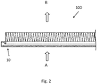
- the air flow L flows through the filter 10 from a raw gas side A to a clean gas side B, see Fig. 2 .
- the filter 100 has a filter element 20 and a frame 10.
- the filter element 20 has a pleated filter medium 21 and an edge strip 22.
- the edge strip 22 has a section 23 which protrudes beyond the bellows formed by the pleated filter medium 21. This section 23 of the edge strip 22 protrudes into the frame 10. More precisely: the section 23 of the edge strip 22 is received in the potting space 12 of the frame 10, which is only open towards the top.
- the frame 10 is filled with a sealing compound 2.
- the sealing potting compound 2 is in contact with the edge strip 22 of the filter element 20 in the area of a contact surface 24 of the edge strip 22 and thus causes the filter element 20 to be glued to the frame 10.
- the frame 10 was filled with the sealing potting compound 2 in this way, that the sealing compound 2 not only causes gluing, but also a seal 1 is formed.
- the seal 1 contacts a bearing surface 201 of the housing 200 and is pressed, whereby a seal is effected.
- the structure of the frame 10 is shown in the sectional view of FIG Figure 3 Shown in more detail:
- the frame 10 is formed from extruded strips 11, which have the already mentioned casting space 12. Adjacent to the bottom of the potting space 12, an undercut 13 is formed, which can also be filled with sealing potting compound 2.
- the frame 10 also has a slot-shaped slot 15 which is used to receive corner connectors (not shown).
- the corner connectors for example in the form of angled metal sheets, can be pushed into the slot 15, a press fit being effected.
- Two strips 11 can be connected to one another by means of a corner connector.
- the frame 10 has a spacer 14, which is designed here as a raised, circumferential web.
- the spacer 14 has the effect that the compression of the seal 1 is limited and the seal 1 retains its sealing effect.
Landscapes
- Chemical & Material Sciences (AREA)
- Chemical Kinetics & Catalysis (AREA)
- Filtering Of Dispersed Particles In Gases (AREA)
Abstract
Description
- Die Erfindung betrifft einen Filter gemäß dem Oberbegriff von Anspruch 1 und eine Filteranordnung mit solchem Filter gemäß dem Anspruch 10.
- Aus der
EP 3 520 878 A1 ist ein Filter bekannt, der einen Rahmen aus extrudierten Profilleisten besitzt. In den Rahmen können Filtermedien für verschiedenen Filterstufen eingesetzt und eingeklebt werden. Am Rahmen ist zusätzlich eine Dichtung vorgesehen, welche den Filter gegen eine Filteraufnahme abdichtet. Nachteilig ist, dass die Dichtung separat angebracht werden muss. - Die
US 2005/0284116 A1 zeigt einen Filter dessen plissiertes Filtermedium in u-förmige, flexible Leisten eingeklebt wird. Das plissierte Filtermedium, auch als Faltenbalg bezeichnet, wird direkt in die Leisten eingeklebt und besitzt keine Kantenstreifen. Erst durch das Einkleben in den Rahmen erhält der Faltenbalg eine ausreichende Stabilität. Die Leisten können eine Dichtlippe aufweisen und durch Extrusion hergestellt sein. Nachteilig ist, dass die Leisten nur eine geringe Eigenstabilität aufweisen und ein zusätzliches Versteifungselement eingebracht werden muss. - Aufgabe der vorliegenden Erfindung ist es einen Filter zu schaffen, welcher einfach und kostengünstig gefertigt werden kann, auch bei Vorhandensein von Varianten in unterschiedlichen Größen.
- Gelöst wird diese Aufgabe durch einen Filter mit den Merkmalen von Anspruch 1.
- Erfindungsgemäß wurde als vorteilhaft erkannt, das plissierte Filtermedium mit mindestens einem Kantenstreifen zu versehen und Kantenstreifen und Rahmen durch Verguss miteinander zu verbinden. Dies wird nachfolgend näher erläutert:
Der erfindungsgemäße Filter besitzt ein Filterelement mit einem Filtermedium zum Filtern eines Fluidstroms, insbesondere eines Luftstroms, wobei das Filtermedium plissiert ist. Der Filter besitzt weiter einen Rahmen zur Aufnahme des Filterelements, insbesondere einen so genannten Kopfrahmen. Der Rahmen ist dabei nicht mit einem den Filter aufnehmenden Gehäuse zu verwechseln. Erfindungsgemäß ist das Filterelement mittels einer Dichtungs-Vergussmasse mit dem Rahmen verklebt und der mindestens eine Kantenstreifen wird von einem Vergussraum aufgenommen: Beim erfindungsgemäßen Filter besitzt der Rahmen einen nutförmigen und umlaufenden Vergussraum, welcher insbesondere nur zu einer Seite hin geöffnet ist. Der Vergussraum dient dazu die Dichtungsvergussmasse aufzunehmen.
Das Filtermedium wird erfindungsgemäß von mindestens einem Kantenstreifen umfasst, welcher auch als Kantenband bezeichnet werden kann. D. h. der Kantenstreifen ist Teil des Filterelements und befindet sich an den Außenkanten des plissierten Filtermediums, bildet also die in Durchströmungsrichtung liegenden Außenflächen des Faltenbalgs. Im Unterschied zu aus dem Stand der Technik bekannten Filtern weist der Filter also sowohl Kantenstreifen als auch Rahmen auf. Ein Abschnitt des Kantenstreifens, insbesondere dessen Ende, wird in dem Vergussraum aufgenommen und von Dichtungs-Vergussmasse umschlossen. Bei der Dichtungs-Vergussmasse handelt es sich um ein gießfähiges, elastisches Material. Ein derartiger Filter hat den Vorteil, dass er einfach und kostengünstig gefertigt werden kann, da das Verkleben des Filterelements mit dem Rahmen des Filters besonders gut automatisiert werden kann, da das Filterelement durch das Vorahnensein des Kantenstreifens bereits über eine gute Eigenstabilität verfügt. Ein weiterer Vorteil ergibt sich durch die Gewichtsersparnis, da Metall nur dort eingesetzt wird wo es aufgrund der Stabilität benötigt wird und Kantenstreifen leichter ist als ein aussließlich aus Metall gebildeter Rahmen. Ein solcher Filter lässt sich auch kostengünstiger fertigen auf Grund der geringeren Materialkosten von Kantenstreifen gegenüber Metall. - Das Filterelement kann mindestens einen überstehenden Kantenstreifen haben, derart, dass die Höhe des Kantenstreifens größer ist als die Höhe des Faltenbalgs aus dem plissierten Filtermedium. In diesem Fall wird der von Dichtungs-Vergussmasse umschlossene Abschnitt durch den überstehenden Bereich des Kantenstreifens gebildet.
- Es hat sich herausgestellt, dass es von Vorteil ist, wenn der Rahmen angrenzend an den Boden des Vergussraums einen Hinterschnitt aufweist, derart dass Dichtungs-Vergussmasse auch in den Hinterschnitt eindringen kann zur Schaffung eines Formschlusses von Dichtungs-Vergussmasse und dem Rahmen, nachdem die Dichtungs-Vergussmasse erstarrt ist. Auf diese Weise wird eine besonders sichere Verbindung von Filterelement, Dichtungs-Vergussmasse und Rahmen erreicht.
- In Weiterbildung der Erfindung wurde als vorteilhaft erkannt, die Dichtungs-Vergussmasse für zwei Zwecke zu nutzen: Verbinden des Filterelements mit einem Rahmen und Ausbilden einer Dichtung:
Der Rahmen besitzt dabei eine umlaufende Dichtung. D. h. die Dichtung ist nicht zum Faltenbalg hin, sondern zur Abdichtung gegenüber einem dem Filter aufnehmenden Gehäuse bzw. gegenüber einer den Filter aufnehmenden Filteraufnahme orientiert und verläuft entlang der Außenkontur des Rahmens. Dabei ist das Filterelement wie schon ausgeführt mittels einer Dichtungs-Vergussmasse mit dem Rahmen verklebt und die Dichtungs-Vergussmasse bildet gleichzeitig die am Rahmen umlaufende Dichtung aus.
Ein derartiger Filter hat den Vorteil, dass er einfach und kostengünstig gefertigt werden kann, da das Verkleben des Filterelements am Rahmen und das Aufbringen einer Dichtung in einem Arbeitsgang mit nur einem Material geschieht. - Bei Versuchen wurde herausgefunden, dass geschäumtes Polyurethan (PU) ein besonders geeignetes Material für die Dichtungs-Vergussmasse ist.
- In einer möglichen, vorteilhaften Ausgestaltung des erfindungsgemäßen Filters ist der Rahmen aus extrudierten Leisten zusammengesetzt. Die extrudierten Leisten sind dabei bevorzugt aus einem biegesteifen Material, wie beispielsweise Kunststoff oder Metall, insbesondere einem thermoplastischen Kunststoff oder Aluminium und können als Extrusionsprofil bezeichnet werden.
- In Weiterbildung des vorstehend beschriebenen Filters sind die Leisten mit Eckverbindern verbunden, zum Beispiel winkligen Blechen, und in den Leisten sind schlitzförmige Steckplätze vorgesehen zum Einführen der Eckverbinder. Steckplätze und Eckverbinder sind dabei insbesondere so ausgestaltet, dass eine Presspassung zwischen Steckplätzen und Eckverbindern besteht. Eine derartige Ausgestaltung hat den Vorteil, dass keine weiteren Fertigungsschritte zum Zusammenbau des Rahmens erforderlich sind, wie zum Beispiel Verschweißen, Verschrauben oder Vernieten. Es genügt vielmehr die Leisten zusammenzustecken. Durch die Dichtungs-Vergussmasse wird die Verbindung dann dauerhaft fixiert.
- In vorteilhafter Weiterbildung des erfindungsgemäßen Filters besitzt der Rahmen mindestens einen Abstandshalter, zum Beispiel eine hervorstehende Nase oder einen erhabenen umlaufenden Steg, zur Begrenzung der maximalen Dichtungskompression der umlaufenden Dichtung in montiertem Zustand. Dazu ist der Abstandshalter an dem Rahmen angrenzend an die Dichtung und zum aufnehmenden Gehäuse hin oder zur aufnehmenden Filteraufnahme hin orientiert.
- Bei dem Filtermedium kann es sich vorteilhaft um einen Vliesstoff handeln.
- Die Erfindung betrifft auch eine Filteranordnung aufweisend einen wie vorstehend beschriebenen Filter und ein Gehäuse bzw. alternativ eine Filteraufnahme, wobei der Filter in dem Gehäuse bzw. alternativ in der Filteraufnahme formschlüssig aufgenommen ist. Der Filter kann in das Gehäuse bzw. die Filteraufnahme eingesetzt und - wenn ein Filterwechsel erforderlich ist - wieder entnommen werden.
- Eine derartige Filteranordnung kann zum Beispiel in der Zuluftfiltration für Kabinen von landwirtschaftlichen Fahrzeugen Verwendung finden.
- Die beschriebene Erfindung und die beschriebenen vorteilhaften Weiterbildungen der Erfindung stellen auch in Kombination miteinander - soweit dies technisch sinnvoll ist - vorteilhafte Weiterbildungen der Erfindung dar.
- Hinsichtlich weiterer Vorteile und in konstruktiver und funktioneller Hinsicht vorteilhafter Ausgestaltungen der Erfindung wird auf die Unteransprüche sowie die Beschreibung von Ausführungsbeispielen unter Bezugnahme auf die beiliegenden Figuren verwiesen.
- Die Erfindung soll an Hand beigefügter Figuren noch näher erläutert werden. Einander entsprechende Elemente und Bauteile sind in den Figuren mit gleichen Bezugszeichen versehen. Zugunsten einer besseren Übersichtlichkeit der Figuren wurde auf eine maßstabsgetreue Darstellung verzichtet.
Es zeigen in schematischer Darstellung - Fig. 1
- eine Detailansicht einer Schnittdarstellung durch die Filteranordnung
- Fig. 2
- einen Ausschnitt einer Schnittdarstellung durch den Filter
- Fig. 3
- eine Schnittdarstellung durch den Rahmen des Filters
-
Figur 1 zeigt einen Ausschnitt einer Schnittdarstellung einer Filteranordnung 1000. Die Filteranordnung 1000 besitzt einen Filter 100, welcher in einem Gehäuse 200 aufgenommen wird. Der Filter 100 wird von einem Luftstrom L durchströmt, wobei der Luftstrom L gefiltert wird. Es erfolgt eine Durchströmung des Filters 10 mit dem Luftstrom L von einer Rohgasseite A hin zu einer Reingasseite B, sieheFig.2 . - Der Filter 100 besitzt ein Filterelement 20 und einen Rahmen 10. Das Filterelement 20 weist ein plissiertes Filtermedium 21 und einen Kantenstreifen 22 auf. Der Kantenstreifen 22 besitzt einen Abschnitt 23, welcher über den durch das plissierte Filtermedium 21 gebildeten Faltenbalg übersteht. Dieser Abschnitt 23 des Kantenstreifens 22 ragt in den Rahmen 10 hinein. Genauer: der Abschnitt 23 des Kantenstreifens 22 wird in dem nur nach oben hin geöffneten Vergussraum 12 des Rahmens 10 aufgenommen. Der Rahmen 10 ist mit einer Dichtungs-Vergussmasse 2 befüllt. Die Dichtungs-Vergussmasse 2 ist im Bereich einer Kontaktfläche 24 des Kantenstreifens 22 mit dem Kantenstreifen 22 des Filterelements 20 in Kontakt und bewirkt so eine Verklebung des Filterelements 20 mit dem Rahmen 10. Der Rahmen 10 wurde dabei derart mit der Dichtungs-Vergussmasse 2 befüllt, dass die Dichtungs-Vergussmasse 2 nicht nur ein Verkleben bewirkt, sondern auch eine Dichtung 1 ausgebildet wird. Wenn der Filter 100 in dem Gehäuse 200 montiert ist, so kontaktiert die Dichtung 1 eine Auflagefläche 201 des Gehäuses 200 und wird verpresst, wobei eine Abdichtung bewirkt wird.
- Der Aufbau des Rahmens 10 ist in der Schnittdarstellung von
Figur 3 näher dargestellt: Der Rahmen 10 wird gebildet aus extrudierten Leisten 11, welche den bereits erwähnten Vergussraum 12 besitzen. Angrenzend an den Boden des Vergussraums 12 ist ein Hinterschnitt 13 ausgebildet, welcher ebenfalls mit Dichtungs-Vergussmasse 2 befüllbar ist. Der Rahmen 10 besitzt auch einen schlitzförmigen Steckplatz 15, welcher der Aufnahme von Eckverbindern (nicht dargestellt) dient. Die Eckverbinder, zum Beispiel in Form von winkligen Blechen, können in den Steckplatz 15 eingeschoben werden, wobei ein Presssitz bewirkt wird. Mittels eines Eckverbinders können zwei Leisten 11 miteinander verbunden werden. - Weiter besitzt der Rahmen 10 einen Abstandshalter 14, welcher hier als erhabener, umlaufender Steg ausgeführt ist. Wie sich aus der Darstellung von
Figur 1 ergibt bewirkt der Abstandshalter 14, dass die Kompression der Dichtung 1 begrenzt wird und die Dichtung 1 ihre Dichtwirkung behält. -
- 1
- Dichtung
- 2
- Dichtungs-Vergussmasse
- 10
- Rahmen
- 11
- extrudierte Leiste
- 12
- Vergussraum
- 13
- Hinterschnitt
- 14
- Abstandshalter
- 15
- Steckplatz für Eckverbinder
- 20
- Filterelement
- 21
- Filtermedium
- 22
- Kantenstreifen
- 23
- Abschnitt Kantenstreifen
- 24
- Kontaktfläche Kantenstreifen für Verklebung
- 100
- Filter
- 200
- Gehäuse / Filteraufnahme
- 201
- Auflagefläche
- 1000
- Filteranaordnung
- A
- Rohgasseite
- B
- Reingasseite
- L
- Luftstrom
Claims (11)
- Filter (100) mit einem Filterelement (20) mit einem Filtermedium (21) zum Filtern eines Fluidstroms (L), insbesondere von Luft, wobei das Filtermedium (21) plissiert ist, mit einem Rahmen (10) zur Aufnahme des Filterelements (20),
dadurch gekennzeichnet, dass
der Rahmen (10) einen Vergussraum (12) aufweist und, dass das Filtermedium (21) von einem Kantenstreifen (22) umfasst wird und ein Abschnitt (23) des Kantenstreifens (22), insbesondere dessen Ende, von dem Vergussraum (12) aufgenommen ist. - Filter nach der Anspruch 1 dadurch gekennzeichnet, dass der Rahmen (10) angrenzend an den Boden des Vergussraums (12) einen Hinterschnitt (13) aufweist.
- Filter nach einem der vorangehenden Ansprüche dadurch gekennzeichnet, dass
der Filter (100) mit einer außen an dem Rahmen umlaufenden Dichtung (1) versehen ist und die Dichtungs-Vergussmasse (2) die umlaufende Dichtung (1) ausbildet. - Filter nach einem der vorangehenden Ansprüche dadurch gekennzeichnet, dass
die Dichtungs-Vergussmasse (2) ein geschäumtes Polyurethan (PU) ist. - Filter nach einem der vorangehenden Ansprüche dadurch gekennzeichnet, dass
der Rahmen (10) aus extrudierten Leisten (11) zusammengesetzt ist. - Filter nach Anspruch 5 dadurch gekennzeichnet, dass die Leisten (11) mit Eckverbindern verbunden sind und in den Leisten (11) Steckplätze (15) vorgesehen sind zum Einfügen der Eckverbinder.
- Filter nach einem der vorangehenden Ansprüche dadurch gekennzeichnet, dass
der Rahmen (10) aus Kunststoff oder Aluminium gebildet ist. - Filter nach einem der vorangehenden Ansprüche dadurch gekennzeichnet, dass
der Rahmen (10) mindestens einen Abstandshalter (14) besitzt zur Begrenzung der maximalen Dichtungskompression. - Filter nach einem der vorangehenden Ansprüche, dadurch gekennzeichnet, dass
das Filtermedium (21) ein Vliesstoff ist. - Filteranordnung (1000) aufweisend einen Filter (100) nach einem der vorangehenden Ansprüche und ein Gehäuse (200), wobei der Filter (100) in dem Gehäuse (200) aufgenommen ist.
- Verwendung einer Filteranordnung nach Anspruch 10 in der Zuluftfiltration für Kabinen von landwirtschaftlichen Fahrzeugen.
Priority Applications (1)
| Application Number | Priority Date | Filing Date | Title |
|---|---|---|---|
| EP20168346.3A EP3892352B1 (de) | 2020-04-07 | 2020-04-07 | Filter mit dichtungsvergussmasse und filteranordnung mit solchem filter |
Applications Claiming Priority (1)
| Application Number | Priority Date | Filing Date | Title |
|---|---|---|---|
| EP20168346.3A EP3892352B1 (de) | 2020-04-07 | 2020-04-07 | Filter mit dichtungsvergussmasse und filteranordnung mit solchem filter |
Publications (2)
| Publication Number | Publication Date |
|---|---|
| EP3892352A1 true EP3892352A1 (de) | 2021-10-13 |
| EP3892352B1 EP3892352B1 (de) | 2023-08-30 |
Family
ID=70227781
Family Applications (1)
| Application Number | Title | Priority Date | Filing Date |
|---|---|---|---|
| EP20168346.3A Active EP3892352B1 (de) | 2020-04-07 | 2020-04-07 | Filter mit dichtungsvergussmasse und filteranordnung mit solchem filter |
Country Status (1)
| Country | Link |
|---|---|
| EP (1) | EP3892352B1 (de) |
Cited By (4)
| Publication number | Priority date | Publication date | Assignee | Title |
|---|---|---|---|---|
| WO2024251489A1 (de) * | 2023-06-06 | 2024-12-12 | Mann+Hummel Gmbh | Flachfilter-filterelement mit wenigstens zwei filtermediumkörpern, filtersystem und verwendung eines flachfilter-filterelements |
| US12403419B1 (en) | 2024-05-17 | 2025-09-02 | Donaldson Company, Inc. | Filter elements and assemblies |
| US12434181B1 (en) | 2024-11-01 | 2025-10-07 | Donaldson Company, Inc. | Air cleaner and filtration assemblies |
| RU242895U1 (ru) * | 2026-02-10 | 2026-04-16 | Общество с ограниченной ответственностью "АэроФильтр" | Устройство для очистки воздуха. |
Citations (6)
| Publication number | Priority date | Publication date | Assignee | Title |
|---|---|---|---|---|
| DE20101237U1 (de) * | 2001-01-24 | 2002-05-29 | McLeodRussel GmbH & Co. OHG, 45549 Sprockhövel | Filterzelle |
| US20020104299A1 (en) * | 2001-02-06 | 2002-08-08 | Yung-Yu Chang | Air filter screen |
| DE10321068A1 (de) * | 2003-05-10 | 2004-12-30 | Mann + Hummel Gmbh | Filterelement |
| US20050284116A1 (en) | 2004-06-28 | 2005-12-29 | 3M Innovative Properties Company | Filter cross brace |
| DE202008007292U1 (de) * | 2008-05-30 | 2009-10-08 | Mann + Hummel Gmbh | Filterelement |
| EP3520878A1 (de) | 2018-02-01 | 2019-08-07 | Carl Freudenberg KG | Filterelement und verwendung eines solchen filterelements |
-
2020
- 2020-04-07 EP EP20168346.3A patent/EP3892352B1/de active Active
Patent Citations (6)
| Publication number | Priority date | Publication date | Assignee | Title |
|---|---|---|---|---|
| DE20101237U1 (de) * | 2001-01-24 | 2002-05-29 | McLeodRussel GmbH & Co. OHG, 45549 Sprockhövel | Filterzelle |
| US20020104299A1 (en) * | 2001-02-06 | 2002-08-08 | Yung-Yu Chang | Air filter screen |
| DE10321068A1 (de) * | 2003-05-10 | 2004-12-30 | Mann + Hummel Gmbh | Filterelement |
| US20050284116A1 (en) | 2004-06-28 | 2005-12-29 | 3M Innovative Properties Company | Filter cross brace |
| DE202008007292U1 (de) * | 2008-05-30 | 2009-10-08 | Mann + Hummel Gmbh | Filterelement |
| EP3520878A1 (de) | 2018-02-01 | 2019-08-07 | Carl Freudenberg KG | Filterelement und verwendung eines solchen filterelements |
Cited By (4)
| Publication number | Priority date | Publication date | Assignee | Title |
|---|---|---|---|---|
| WO2024251489A1 (de) * | 2023-06-06 | 2024-12-12 | Mann+Hummel Gmbh | Flachfilter-filterelement mit wenigstens zwei filtermediumkörpern, filtersystem und verwendung eines flachfilter-filterelements |
| US12403419B1 (en) | 2024-05-17 | 2025-09-02 | Donaldson Company, Inc. | Filter elements and assemblies |
| US12434181B1 (en) | 2024-11-01 | 2025-10-07 | Donaldson Company, Inc. | Air cleaner and filtration assemblies |
| RU242895U1 (ru) * | 2026-02-10 | 2026-04-16 | Общество с ограниченной ответственностью "АэроФильтр" | Устройство для очистки воздуха. |
Also Published As
| Publication number | Publication date |
|---|---|
| EP3892352B1 (de) | 2023-08-30 |
Similar Documents
| Publication | Publication Date | Title |
|---|---|---|
| EP1134014B2 (de) | Filtereinsatz | |
| EP3078408B1 (de) | Filterelement mit lasche und filtersystem | |
| EP3892352B1 (de) | Filter mit dichtungsvergussmasse und filteranordnung mit solchem filter | |
| EP0715876B1 (de) | Taschenfilter | |
| EP3520878B1 (de) | Filterelement und verwendung eines solchen filterelements | |
| DE102012019320B4 (de) | Stützeinrichtung eines Filters, Flachfilterelement eines Filters und Filter | |
| DE102008028834A1 (de) | Komprimierbares Filterelement mit zueinander geneigten Endkappen | |
| EP1894610A1 (de) | Flexibles Filterelement | |
| EP2849868A1 (de) | Innenraumfilter und filterelement für einen innenraumfilter | |
| DE102010025971B4 (de) | Filter zur Filtrierung von Fluiden und Filtereinsatz | |
| DE102014224764A1 (de) | Filterelement | |
| EP3744414A1 (de) | Filter mit umgefaltetem kantenband | |
| DE10249110B4 (de) | Filtereinrichtung, Filterelement und Filterrahmen | |
| DE4323522A1 (de) | Filterelement aus zick-zack-förmig gefaltetem Filterbahnmaterial | |
| DE102010024093A1 (de) | Innenraumluftfilterelement, Filteraufnahme, Filteranordnung und Verfahren zum Herstellen des Innenraumluftfilterelements | |
| EP3065846B1 (de) | Plattenfilterelement | |
| DE112019005946B4 (de) | Flüssigkeitsfilter und Verwendung | |
| DE102004031609A1 (de) | Filterelement mit Dichtlippe | |
| DE69413825T2 (de) | Filtriervorrichtung fuer eine kühlanordnung und herstellverfahren einer solchen vorrichtung | |
| DE102010013120B4 (de) | Filterelement zur Luftfilterung | |
| EP3960273B1 (de) | Kassettenfilter mit filterelement mit spezialfaltung | |
| EP4011480A1 (de) | Klappbare filteranordnung bestehend aus mehreren einzelfilterelementen | |
| DE10235122B3 (de) | Flexibler Filter | |
| EP3981491A1 (de) | Filteranordnung mit filterelement und filtergehäuse | |
| EP3750615B1 (de) | Filterelement mit spezialfaltung und kassettenfilter mit solchen filterelementen und filterpatrone mit einem solchen filterelement |
Legal Events
| Date | Code | Title | Description |
|---|---|---|---|
| PUAI | Public reference made under article 153(3) epc to a published international application that has entered the european phase |
Free format text: ORIGINAL CODE: 0009012 |
|
| STAA | Information on the status of an ep patent application or granted ep patent |
Free format text: STATUS: THE APPLICATION HAS BEEN PUBLISHED |
|
| AK | Designated contracting states |
Kind code of ref document: A1 Designated state(s): AL AT BE BG CH CY CZ DE DK EE ES FI FR GB GR HR HU IE IS IT LI LT LU LV MC MK MT NL NO PL PT RO RS SE SI SK SM TR |
|
| STAA | Information on the status of an ep patent application or granted ep patent |
Free format text: STATUS: REQUEST FOR EXAMINATION WAS MADE |
|
| 17P | Request for examination filed |
Effective date: 20211020 |
|
| RBV | Designated contracting states (corrected) |
Designated state(s): AL AT BE BG CH CY CZ DE DK EE ES FI FR GB GR HR HU IE IS IT LI LT LU LV MC MK MT NL NO PL PT RO RS SE SI SK SM TR |
|
| STAA | Information on the status of an ep patent application or granted ep patent |
Free format text: STATUS: EXAMINATION IS IN PROGRESS |
|
| 17Q | First examination report despatched |
Effective date: 20220225 |
|
| GRAP | Despatch of communication of intention to grant a patent |
Free format text: ORIGINAL CODE: EPIDOSNIGR1 |
|
| STAA | Information on the status of an ep patent application or granted ep patent |
Free format text: STATUS: GRANT OF PATENT IS INTENDED |
|
| INTG | Intention to grant announced |
Effective date: 20230411 |
|
| GRAS | Grant fee paid |
Free format text: ORIGINAL CODE: EPIDOSNIGR3 |
|
| GRAA | (expected) grant |
Free format text: ORIGINAL CODE: 0009210 |
|
| STAA | Information on the status of an ep patent application or granted ep patent |
Free format text: STATUS: THE PATENT HAS BEEN GRANTED |
|
| AK | Designated contracting states |
Kind code of ref document: B1 Designated state(s): AL AT BE BG CH CY CZ DE DK EE ES FI FR GB GR HR HU IE IS IT LI LT LU LV MC MK MT NL NO PL PT RO RS SE SI SK SM TR |
|
| REG | Reference to a national code |
Ref country code: GB Ref legal event code: FG4D Free format text: NOT ENGLISH |
|
| REG | Reference to a national code |
Ref country code: CH Ref legal event code: EP |
|
| P01 | Opt-out of the competence of the unified patent court (upc) registered |
Effective date: 20230808 |
|
| REG | Reference to a national code |
Ref country code: DE Ref legal event code: R096 Ref document number: 502020004921 Country of ref document: DE |
|
| REG | Reference to a national code |
Ref country code: IE Ref legal event code: FG4D Free format text: LANGUAGE OF EP DOCUMENT: GERMAN |
|
| REG | Reference to a national code |
Ref country code: LT Ref legal event code: MG9D |
|
| REG | Reference to a national code |
Ref country code: NL Ref legal event code: MP Effective date: 20230830 |
|
| PG25 | Lapsed in a contracting state [announced via postgrant information from national office to epo] |
Ref country code: GR Free format text: LAPSE BECAUSE OF FAILURE TO SUBMIT A TRANSLATION OF THE DESCRIPTION OR TO PAY THE FEE WITHIN THE PRESCRIBED TIME-LIMIT Effective date: 20231201 |
|
| PG25 | Lapsed in a contracting state [announced via postgrant information from national office to epo] |
Ref country code: IS Free format text: LAPSE BECAUSE OF FAILURE TO SUBMIT A TRANSLATION OF THE DESCRIPTION OR TO PAY THE FEE WITHIN THE PRESCRIBED TIME-LIMIT Effective date: 20231230 |
|
| PG25 | Lapsed in a contracting state [announced via postgrant information from national office to epo] |
Ref country code: SE Free format text: LAPSE BECAUSE OF FAILURE TO SUBMIT A TRANSLATION OF THE DESCRIPTION OR TO PAY THE FEE WITHIN THE PRESCRIBED TIME-LIMIT Effective date: 20230830 Ref country code: RS Free format text: LAPSE BECAUSE OF FAILURE TO SUBMIT A TRANSLATION OF THE DESCRIPTION OR TO PAY THE FEE WITHIN THE PRESCRIBED TIME-LIMIT Effective date: 20230830 Ref country code: NO Free format text: LAPSE BECAUSE OF FAILURE TO SUBMIT A TRANSLATION OF THE DESCRIPTION OR TO PAY THE FEE WITHIN THE PRESCRIBED TIME-LIMIT Effective date: 20231130 Ref country code: LV Free format text: LAPSE BECAUSE OF FAILURE TO SUBMIT A TRANSLATION OF THE DESCRIPTION OR TO PAY THE FEE WITHIN THE PRESCRIBED TIME-LIMIT Effective date: 20230830 Ref country code: LT Free format text: LAPSE BECAUSE OF FAILURE TO SUBMIT A TRANSLATION OF THE DESCRIPTION OR TO PAY THE FEE WITHIN THE PRESCRIBED TIME-LIMIT Effective date: 20230830 Ref country code: IS Free format text: LAPSE BECAUSE OF FAILURE TO SUBMIT A TRANSLATION OF THE DESCRIPTION OR TO PAY THE FEE WITHIN THE PRESCRIBED TIME-LIMIT Effective date: 20231230 Ref country code: HR Free format text: LAPSE BECAUSE OF FAILURE TO SUBMIT A TRANSLATION OF THE DESCRIPTION OR TO PAY THE FEE WITHIN THE PRESCRIBED TIME-LIMIT Effective date: 20230830 Ref country code: GR Free format text: LAPSE BECAUSE OF FAILURE TO SUBMIT A TRANSLATION OF THE DESCRIPTION OR TO PAY THE FEE WITHIN THE PRESCRIBED TIME-LIMIT Effective date: 20231201 Ref country code: FI Free format text: LAPSE BECAUSE OF FAILURE TO SUBMIT A TRANSLATION OF THE DESCRIPTION OR TO PAY THE FEE WITHIN THE PRESCRIBED TIME-LIMIT Effective date: 20230830 |
|
| PG25 | Lapsed in a contracting state [announced via postgrant information from national office to epo] |
Ref country code: PL Free format text: LAPSE BECAUSE OF FAILURE TO SUBMIT A TRANSLATION OF THE DESCRIPTION OR TO PAY THE FEE WITHIN THE PRESCRIBED TIME-LIMIT Effective date: 20230830 Ref country code: NL Free format text: LAPSE BECAUSE OF FAILURE TO SUBMIT A TRANSLATION OF THE DESCRIPTION OR TO PAY THE FEE WITHIN THE PRESCRIBED TIME-LIMIT Effective date: 20230830 |
|
| PG25 | Lapsed in a contracting state [announced via postgrant information from national office to epo] |
Ref country code: ES Free format text: LAPSE BECAUSE OF FAILURE TO SUBMIT A TRANSLATION OF THE DESCRIPTION OR TO PAY THE FEE WITHIN THE PRESCRIBED TIME-LIMIT Effective date: 20230830 |
|
| PG25 | Lapsed in a contracting state [announced via postgrant information from national office to epo] |
Ref country code: SM Free format text: LAPSE BECAUSE OF FAILURE TO SUBMIT A TRANSLATION OF THE DESCRIPTION OR TO PAY THE FEE WITHIN THE PRESCRIBED TIME-LIMIT Effective date: 20230830 Ref country code: RO Free format text: LAPSE BECAUSE OF FAILURE TO SUBMIT A TRANSLATION OF THE DESCRIPTION OR TO PAY THE FEE WITHIN THE PRESCRIBED TIME-LIMIT Effective date: 20230830 Ref country code: ES Free format text: LAPSE BECAUSE OF FAILURE TO SUBMIT A TRANSLATION OF THE DESCRIPTION OR TO PAY THE FEE WITHIN THE PRESCRIBED TIME-LIMIT Effective date: 20230830 Ref country code: EE Free format text: LAPSE BECAUSE OF FAILURE TO SUBMIT A TRANSLATION OF THE DESCRIPTION OR TO PAY THE FEE WITHIN THE PRESCRIBED TIME-LIMIT Effective date: 20230830 Ref country code: DK Free format text: LAPSE BECAUSE OF FAILURE TO SUBMIT A TRANSLATION OF THE DESCRIPTION OR TO PAY THE FEE WITHIN THE PRESCRIBED TIME-LIMIT Effective date: 20230830 Ref country code: CZ Free format text: LAPSE BECAUSE OF FAILURE TO SUBMIT A TRANSLATION OF THE DESCRIPTION OR TO PAY THE FEE WITHIN THE PRESCRIBED TIME-LIMIT Effective date: 20230830 Ref country code: PT Free format text: LAPSE BECAUSE OF FAILURE TO SUBMIT A TRANSLATION OF THE DESCRIPTION OR TO PAY THE FEE WITHIN THE PRESCRIBED TIME-LIMIT Effective date: 20240102 Ref country code: SK Free format text: LAPSE BECAUSE OF FAILURE TO SUBMIT A TRANSLATION OF THE DESCRIPTION OR TO PAY THE FEE WITHIN THE PRESCRIBED TIME-LIMIT Effective date: 20230830 |
|
| REG | Reference to a national code |
Ref country code: DE Ref legal event code: R026 Ref document number: 502020004921 Country of ref document: DE |
|
| PLBI | Opposition filed |
Free format text: ORIGINAL CODE: 0009260 |
|
| PLAX | Notice of opposition and request to file observation + time limit sent |
Free format text: ORIGINAL CODE: EPIDOSNOBS2 |
|
| PLAX | Notice of opposition and request to file observation + time limit sent |
Free format text: ORIGINAL CODE: EPIDOSNOBS2 |
|
| 26 | Opposition filed |
Opponent name: MANN + HUMMEL GMBH Effective date: 20240531 |
|
| PG25 | Lapsed in a contracting state [announced via postgrant information from national office to epo] |
Ref country code: SI Free format text: LAPSE BECAUSE OF FAILURE TO SUBMIT A TRANSLATION OF THE DESCRIPTION OR TO PAY THE FEE WITHIN THE PRESCRIBED TIME-LIMIT Effective date: 20230830 |
|
| PLBB | Reply of patent proprietor to notice(s) of opposition received |
Free format text: ORIGINAL CODE: EPIDOSNOBS3 |
|
| PG25 | Lapsed in a contracting state [announced via postgrant information from national office to epo] |
Ref country code: BG Free format text: LAPSE BECAUSE OF FAILURE TO SUBMIT A TRANSLATION OF THE DESCRIPTION OR TO PAY THE FEE WITHIN THE PRESCRIBED TIME-LIMIT Effective date: 20230830 |
|
| PG25 | Lapsed in a contracting state [announced via postgrant information from national office to epo] |
Ref country code: MC Free format text: LAPSE BECAUSE OF FAILURE TO SUBMIT A TRANSLATION OF THE DESCRIPTION OR TO PAY THE FEE WITHIN THE PRESCRIBED TIME-LIMIT Effective date: 20230830 |
|
| PG25 | Lapsed in a contracting state [announced via postgrant information from national office to epo] |
Ref country code: MC Free format text: LAPSE BECAUSE OF FAILURE TO SUBMIT A TRANSLATION OF THE DESCRIPTION OR TO PAY THE FEE WITHIN THE PRESCRIBED TIME-LIMIT Effective date: 20230830 Ref country code: BG Free format text: LAPSE BECAUSE OF FAILURE TO SUBMIT A TRANSLATION OF THE DESCRIPTION OR TO PAY THE FEE WITHIN THE PRESCRIBED TIME-LIMIT Effective date: 20230830 |
|
| REG | Reference to a national code |
Ref country code: CH Ref legal event code: PL |
|
| PG25 | Lapsed in a contracting state [announced via postgrant information from national office to epo] |
Ref country code: LU Free format text: LAPSE BECAUSE OF NON-PAYMENT OF DUE FEES Effective date: 20240407 |
|
| GBPC | Gb: european patent ceased through non-payment of renewal fee |
Effective date: 20240407 |
|
| REG | Reference to a national code |
Ref country code: BE Ref legal event code: MM Effective date: 20240430 |
|
| PG25 | Lapsed in a contracting state [announced via postgrant information from national office to epo] |
Ref country code: LU Free format text: LAPSE BECAUSE OF NON-PAYMENT OF DUE FEES Effective date: 20240407 |
|
| PG25 | Lapsed in a contracting state [announced via postgrant information from national office to epo] |
Ref country code: BE Free format text: LAPSE BECAUSE OF NON-PAYMENT OF DUE FEES Effective date: 20240430 |
|
| PG25 | Lapsed in a contracting state [announced via postgrant information from national office to epo] |
Ref country code: GB Free format text: LAPSE BECAUSE OF NON-PAYMENT OF DUE FEES Effective date: 20240407 |
|
| PG25 | Lapsed in a contracting state [announced via postgrant information from national office to epo] |
Ref country code: FR Free format text: LAPSE BECAUSE OF NON-PAYMENT OF DUE FEES Effective date: 20240430 |
|
| PG25 | Lapsed in a contracting state [announced via postgrant information from national office to epo] |
Ref country code: GB Free format text: LAPSE BECAUSE OF NON-PAYMENT OF DUE FEES Effective date: 20240407 Ref country code: FR Free format text: LAPSE BECAUSE OF NON-PAYMENT OF DUE FEES Effective date: 20240430 Ref country code: BE Free format text: LAPSE BECAUSE OF NON-PAYMENT OF DUE FEES Effective date: 20240430 Ref country code: CH Free format text: LAPSE BECAUSE OF NON-PAYMENT OF DUE FEES Effective date: 20240430 |
|
| PG25 | Lapsed in a contracting state [announced via postgrant information from national office to epo] |
Ref country code: IE Free format text: LAPSE BECAUSE OF NON-PAYMENT OF DUE FEES Effective date: 20240407 |
|
| PGFP | Annual fee paid to national office [announced via postgrant information from national office to epo] |
Ref country code: DE Payment date: 20250428 Year of fee payment: 6 |
|
| PGFP | Annual fee paid to national office [announced via postgrant information from national office to epo] |
Ref country code: IT Payment date: 20250422 Year of fee payment: 6 |
|
| PGFP | Annual fee paid to national office [announced via postgrant information from national office to epo] |
Ref country code: AT Payment date: 20250721 Year of fee payment: 5 |
|
| PG25 | Lapsed in a contracting state [announced via postgrant information from national office to epo] |
Ref country code: CY Free format text: LAPSE BECAUSE OF FAILURE TO SUBMIT A TRANSLATION OF THE DESCRIPTION OR TO PAY THE FEE WITHIN THE PRESCRIBED TIME-LIMIT; INVALID AB INITIO Effective date: 20200407 |
|
| PG25 | Lapsed in a contracting state [announced via postgrant information from national office to epo] |
Ref country code: HU Free format text: LAPSE BECAUSE OF FAILURE TO SUBMIT A TRANSLATION OF THE DESCRIPTION OR TO PAY THE FEE WITHIN THE PRESCRIBED TIME-LIMIT; INVALID AB INITIO Effective date: 20200407 |
|
| APBP | Date of receipt of notice of appeal recorded |
Free format text: ORIGINAL CODE: EPIDOSNNOA2O |
|
| APAH | Appeal reference modified |
Free format text: ORIGINAL CODE: EPIDOSCREFNO |
|
| APAW | Appeal reference deleted |
Free format text: ORIGINAL CODE: EPIDOSDREFNO |
|
| APBU | Appeal procedure closed |
Free format text: ORIGINAL CODE: EPIDOSNNOA9O |