EP3891069B1 - Housing structure provided with a deployable supporting frame. for aerospace applications - Google Patents
Housing structure provided with a deployable supporting frame. for aerospace applications Download PDFInfo
- Publication number
- EP3891069B1 EP3891069B1 EP19835483.9A EP19835483A EP3891069B1 EP 3891069 B1 EP3891069 B1 EP 3891069B1 EP 19835483 A EP19835483 A EP 19835483A EP 3891069 B1 EP3891069 B1 EP 3891069B1
- Authority
- EP
- European Patent Office
- Prior art keywords
- rods
- supporting frame
- housing structure
- aerospace
- structure according
- Prior art date
- Legal status (The legal status is an assumption and is not a legal conclusion. Google has not performed a legal analysis and makes no representation as to the accuracy of the status listed.)
- Active
Links
Images


Classifications
-
- B—PERFORMING OPERATIONS; TRANSPORTING
- B64—AIRCRAFT; AVIATION; COSMONAUTICS
- B64G—COSMONAUTICS; VEHICLES OR EQUIPMENT THEREFOR
- B64G1/00—Cosmonautic vehicles
- B64G1/22—Parts of, or equipment specially adapted for fitting in or to, cosmonautic vehicles
- B64G1/52—Protection, safety or emergency devices; Survival aids
- B64G1/54—Protection against radiation
- B64G1/543—Protection against radiation protecting the crew in manned spacecraft
-
- B—PERFORMING OPERATIONS; TRANSPORTING
- B64—AIRCRAFT; AVIATION; COSMONAUTICS
- B64G—COSMONAUTICS; VEHICLES OR EQUIPMENT THEREFOR
- B64G1/00—Cosmonautic vehicles
- B64G1/22—Parts of, or equipment specially adapted for fitting in or to, cosmonautic vehicles
- B64G1/60—Crew or passenger accommodations
-
- B—PERFORMING OPERATIONS; TRANSPORTING
- B64—AIRCRAFT; AVIATION; COSMONAUTICS
- B64G—COSMONAUTICS; VEHICLES OR EQUIPMENT THEREFOR
- B64G1/00—Cosmonautic vehicles
- B64G1/22—Parts of, or equipment specially adapted for fitting in or to, cosmonautic vehicles
-
- B—PERFORMING OPERATIONS; TRANSPORTING
- B64—AIRCRAFT; AVIATION; COSMONAUTICS
- B64G—COSMONAUTICS; VEHICLES OR EQUIPMENT THEREFOR
- B64G1/00—Cosmonautic vehicles
- B64G1/22—Parts of, or equipment specially adapted for fitting in or to, cosmonautic vehicles
- B64G1/222—Parts of, or equipment specially adapted for fitting in or to, cosmonautic vehicles for deploying structures between a stowed and deployed state
- B64G1/2221—Parts of, or equipment specially adapted for fitting in or to, cosmonautic vehicles for deploying structures between a stowed and deployed state characterised by the manner of deployment
- B64G1/2222—Folding
- B64G1/2223—Folding via scissor linkage
-
- E—FIXED CONSTRUCTIONS
- E04—BUILDING
- E04B—GENERAL BUILDING CONSTRUCTIONS; WALLS, e.g. PARTITIONS; ROOFS; FLOORS; CEILINGS; INSULATION OR OTHER PROTECTION OF BUILDINGS
- E04B1/00—Constructions in general; Structures which are not restricted either to walls, e.g. partitions, or floors or ceilings or roofs
- E04B1/343—Structures characterised by movable, separable, or collapsible parts, e.g. for transport
- E04B1/344—Structures characterised by movable, separable, or collapsible parts, e.g. for transport with hinged parts
- E04B1/3441—Structures characterised by movable, separable, or collapsible parts, e.g. for transport with hinged parts with articulated bar-shaped elements
Definitions
- the present invention relates to a deployable supporting frame for aerospace applications.
- the present invention relates to a supporting frame which, once deployed, forms a housing structure for use in a space station, for example to obtain a living cell (i.e. a crew housing), a shelf with two or more compartments, a radiation shelter for the crew, or a work area.
- a living cell i.e. a crew housing
- a shelf with two or more compartments i.e. a radiation shelter for the crew, or a work area.
- housings are already known that are provided with a folding or compactable supporting frame, i.e. a frame that can be configured in a folded condition, to allow its transport, or in a deployed condition to form the housing, to store objects and/or accommodate people.
- a folding or compactable supporting frame i.e. a frame that can be configured in a folded condition, to allow its transport, or in a deployed condition to form the housing, to store objects and/or accommodate people.
- a folding or compactable supporting frame i.e. a frame that can be configured in a folded condition, to allow its transport, or in a deployed condition to form the housing, to store objects and/or accommodate people.
- folding frames of a known type in the folded configuration, do not have the structural characteristics such as to withstand the accelerations (more than ten times the acceleration of gravity) to which they would be subjected during space station launches.
- the supporting frames must satisfy practically opposite requirements, i.e. have structural characteristics such as to be lightweight. Regarding the latter, weight reduction is an essential element for minimising the costs and energy required for launching into space. More specifically, the supporting frame should not be oversized, as in its deployed configuration the forces to which the supporting frame is subjected during in-orbit parking are relatively low (e.g., the supporting frame must withstand impulsive forces of about 70 N, i.e., a force caused by accidental kicking by a crew member).
- folding frames of a known type, in the folded configuration are not the right size for passing through the space hatches that are currently being designed.
- the support frames must satisfy practically opposite requirements, i.e. they must be of such dimensions as to define a living space with a minimum volume, established by the agencies responsible for space programmes.
- US5016418A discloses a deployable structure that synchronously deploys in both length and width and is suitable for use as a structural component for orbiting space stations or large satellites.
- the structure is designed with maximum packing efficiency so that large structures may be collapsed and transported in the cargo bay of the Space Shuttle.
- the structure is made up of interconnected structural units, connected with hinged and fixed connections at connection nodes.
- CN206050100U relates to an extending arm, which is applied to an aerospace environment and is formed by arranging a plurality of folding and unfolding units in series: the length of the extending arm can be changed by changing the number of the folding and unfolding units.
- WO2009148652A2 discloses a structure according to the preamble of claim 1, with a box-shaped unit which holds panels to protect personnel and assets against external force and impacts.
- the purpose of the present invention is, therefore, to provide a housing structure provided with a deployable supporting frame for aerospace applications, which meets the needs set out above in a simple and economical manner and, in particular, has a small size, such as to be able to pass through the space hatches that are currently being designed and allows the housing structure to be assembled directly inside a space station in a simple and fast manner.
- this housing structure should be configurable in order to be able to adapt the space and equipment inside the space station effectively according to the needs of the crew.
- an aerospace housing structure as defined in claim 1, is provided.
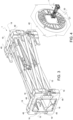
- reference number 1 denotes an aerospace supporting frame, having a substantially parallelepiped shape and comprising a plurality of rods 2a,2b,2c,2d that are coupled so as to be able to rotate relative to each other and thereby manually configure the frame 1, between a deployed operating condition ( Fig. 1 ) and a compacted or folded operating condition ( Fig. 2 ).
- each base 3 consists of a pair of rods 2a, which comprise respective ends 8a and respective intermediate portions 9a: the intermediate portions 9a are hinged to each other so as to form a cross.
- the hinge axes provided at the ends 8a and the intermediate portions 9a are parallel to the direction 6.
- the rods 2a have a fixed length and, in more detail, are straight.
- each of the rods 2b is arranged on two sides 10 of the supporting frame 1.
- the sides 10 lie on planes spaced apart and substantially parallel to each other, are connected to each other by the rods 2a of the bases 3, and face each other along a direction 11, which is orthogonal to the direction 6 and therefore, in the deployed condition during use, is horizontal.
- the rods 2b are similar to the rods 2a, from a constructive point of view and from the point of view of mutual assembly.
- the rods 2b are the same length as the rods 2a.
- each of the rods 2b comprises:
- the hinge axes of the rods 2b are parallel to the direction 11.
- pantograph structure or leverage on each side 10 and on each base 3 starting from the deployed condition, said pantograph leverages allow the bases 3 to approach each other along the direction 6 and the sides 10 to approach each other along the direction 11 relatively easily and quickly in order to switch to the compacted condition.
- the height of the frame 1 along the direction 6 decreases from a value H1 to a value H2
- the width of the frame 1 along the direction 11 decreases from a value D1 to a value D2
- the length of the bases 10 and therefore of the frame 1 along a direction 12 orthogonal to the directions 6 and 11 increases from a value L1 to a value L2.
- the aforementioned rods 2c and 2d have a length that is adjustable, for example they are defined by telescopic rods, i.e. with two parts sliding with respect to each other.
- the rods 2c and 2d are parallel to the direction 12 and are arranged along the sides 10.
- the rods 2c and 2d must extend from the length value L1 to the length value L2.
- a locking system is provided to stop the extension and possibly the shortening of each of the rods 2c and 2d, for example to stop the reciprocal sliding of the two parts of which each rod 2c,2d consists.
- the rods 2c are arranged substantially centrally between the bases 3 (in relation to the direction 6), while the rods 2d are substantially coplanar to the bases 3, i.e. they are arranged at the edges of the frame 1, at virtual intersections between the bases 3 and the sides 10.
- each side 10 there are two rods 2c, arranged in proximity, even if spaced apart along the direction 6.
- the rods 2c comprise respective ends 8c that are carried by two coupling elements 15 opposite each other and hinged to the ends 10b of the rods 2b.
- the rods 2d comprise respective ends 8d that are carried by coupling elements 16, arranged at the eight vertices of the frame 1 and thus defining respective angle elements.
- Each of the coupling elements 16 is hinged to one of the ends 8a and to one of the ends 8b, in addition to being coupled to one of the ends 8d of the rods 2d.
- the coupling elements 15 and 16 are spaced apart from each other.
- at least some of the elements 15 and 16 i.e. at least the elements 16
- the elements 15 and 16 define respective nodes that are hinged to the ends of the rods and that cooperate with each other, in the compacted condition, to create a system suitable for absorbing loads.
- each of the supporting members 18 has a ring shape, and its nodes are arranged in series along this ring.
- each node is interposed between, and is in contact against, two adjacent nodes.
- the coupling mode for coupling these nodes defines at least two contact bearings directed along respective X and Y directions that are orthogonal to each other and are parallel, respectively, to the directions 11 and 6.
- each of these nodes has two abutment shoulders that are orthogonal to said directions X and Y, respectively, and are in contact against corresponding abutment shoulders of the adjacent node.
- Each of the nodes defined by the elements 16 is an angle node comprising a body 16a and a flap 16b, protruding cantilevered from the body 16a along the direction 12.
- Each flap 16b comprises two straight portions 16c and 16d that are orthogonal and joined to each other, and are parallel to the directions 11 and 6, respectively.
- the portions 16c are aligned with each other parallel to the direction 11, and at least one of the portions 16c protrudes relative to the body 16a of its node so as to couple to the portion 16c of the adjacent node.
- the bodies 16a of two adjacent nodes are spaced apart from each other; at the same time, the end of one of the two portions 16c forms a seat 16g, which has a step shape, is engaged by the end of the other portion 16c and is bounded by two abutment shoulders 16e and 16f, that are orthogonal to the aforementioned directions X and Y and are in contact with corresponding shoulders of the other portion 16c.
- the flaps 16b define the contact coupling along both the directions X and Y, in the case of adjacent nodes both defined by elements 16.
- the element 15 comprises a body 15a and a flap 15b, which protrudes cantilevered from the body 15a along the direction 12 and is straight and parallel to the direction 6.
- the flap 15b protrudes relative to the body 15a parallel to the direction 6 so as to couple to the portion 16d of the adjacent node, which is defined by the element 16 (according to variants not illustrated, the portion 16d protrudes from the body 16a to couple to the flap 15b).
- the end of the flap 15b has an abutment shoulder 15e that is orthogonal to the direction X and is in contact against a corresponding shoulder of the end of the portion 16d.
- the body 15a has an abutment shoulder 15f that is orthogonal to the Y direction and is in contact against a corresponding shoulder of the body 16a.
- the contact bearings along the directions X and Y are defined, one, by the flaps 15b and 16b and, the other, by the bodies 16a and 16b.
- the adjacent nodes defined by the elements 15 and 16 are preferably also in contact against each other along a direction Z, parallel to the direction 12.
- the end of the flap 15b has an abutment shoulder 15g in contact against the body 16a of the adjacent node, along this direction Z (according to non-illustrated variants, it is the end of the portion 16d that is resting on the body 15a).
- the elements 15 and 16 have a reference system, one with respect to the other, for defining a correct relative positioning of the nodes in the compacted condition.
- the supporting members 18 can be wound by belts 19 or similar extended elements, preferably flexible (ropes, cables, etc.), to retain the elements 15 and 16 in a fixed position, in contact with each other, and to prevent the frame 1 from deploying autonomously and/or accidentally.
- an intermediate cover is placed between each member 18 and the relative belt 19.
- This intermediate cover is defined, for example, by two C-shaped half-shells, or by four covering elements, each of which has an angular shape and is coupled to a respective element 16 so as to cover the latter (while the elements 15 may remain uncovered).
- such covering elements are defined by the same elements 48 that will be described below with reference to Figure 9 .
- the compacted condition is used to launch the frame 1 into an orbiting space station 20 (partially illustrated).
- the loads due to space launch are absorbed by the nodes defined by the elements 15 and 16, with a consequent advantage in saving mass from a structural point of view. In fact, in this way, it is possible to lighten the structure of the rods that are arranged between the members 18 in the compacted condition.
- the dimensions of the frame 1 defined by the height value H2 and the width value D2 are extremely small, as explained above, so that the frame 1 can enter the station 20 through its relatively small hatch 21.
- the frame 1 is without rods on one side (i.e. at the front end), while it comprises a plurality of rods 2e on the other side (at the rear end) .
- the rods 2e comprise respective ends 8e that are coupled to the coupling elements 15 and/or 16 by means of joints 22 ( Fig. 6 ) that allow the rods 2e to be arranged in a first position ( Fig.5 ) or in a second position ( Fig.7 ).
- the elements 15 and 16 arranged at the rear end may differ slightly from the elements 15 and 16 arranged at the front end, in terms of structure/shape and/or dimensions.
- the rods 2e lie on a plane orthogonal to the direction 12 and are fixed together in a releasable manner by at least one fastening device 23.
- the device 23 comprises a locking rod 24 that is coupled in a sliding manner to one of the rods 2e to move to and from a locked position, wherein it is simultaneously fastened to the ends of four rods 2e so as to hold them in a fixed position with respect to each other, thus forming a cross.
- the rods 2e perform a stiffening function for the frame 1 at the rear end in the deployed condition.
- the rods 2e are uncoupled from each other and protrude cantilevered from respective coupling elements 15 and 16, in positions facing and parallel to the rods 2c and 2d.
- the devices 23 To switch from the deployed to the compacted condition, the devices 23 must first be released to uncouple the rods 2e from each other ( Fig. 6 ), and then the rods 2e must be rotated around the joints 22 to arrange them in their second position ( Fig. 7 ). After these operations, and after unlocking the extension of the rods 2c and 2d, it is possible to close the frame 1 in the compacted condition by bringing the coupling elements 15 and 16 closer together so as to touch.
- the pantograph leverages defined by the rods 2a and 2b close, so as to bring the rods 2d closer together along the directions 6 and 11, while maintaining the parallelism of the rods 2c and 2d.
- This closing or compacting movement ends when the elements 16 come into contact with the elements 15 and, thus, form the two supporting members 18.
- the rods 2a, 2b, 2c and 2d continue to remain along the bases 3 and sides 10 of the frame 1 and define a cavity 26 that is elongated along the direction 12, houses the rods 2e, and is open at the two opposite longitudinal ends of the frame 1.
- the frame 1 When the frame 1 is arranged in its deployed condition, it is normally used to form a housing structure 30, as shown in Figures 8 to 12 .
- the frame 1 is joined to at least one covering element, arranged along at least one of the bases 3 and/or sides 10.
- the structure 30 is assembled by mounting, in a releasable manner, at least one rigid panel 32 in the space inside the frame 1.
- two horizontal panels 32 are arranged to cover the bases 3, as floor and roof, while an additional horizontal panel 32 is coupled to the elements 15 in a fixed position, as an intermediate shelf.
- the structure 30 defines a shelf that is partially open at the side and rear, as well as being fully open at the front to ensure access to its interior.
- the structure 30 comprises at least two uprights 34, which are parallel to the direction 6, are arranged at the front ends of sides 10 of the frame 1 and, in particular, are attached to the elements 15 and 16 that are arranged at said front ends.
- the uprights 34 are provided with respective rows of fasteners or connectors 27, which can be used as an alternative to each other to couple one or more components to the frame 1 in a desired position.
- the connectors 27 of the uprights 34 can be used to couple a hook 35 to hang objects and/or a support arm 36 for a keyboard or tray, at any height.
- the structure 30 comprises a canvas cover 40, which is arranged around the frame 1, as the outer covering of at least one of the bases 3 (the upper one), the sides 10, and the rear end of the frame 1.
- the canvas 40 is tensioned when coupled to the frame 1, so as to form a tensile structure and further stiffen the frame 1, as with an umbrella.
- the canvas 40 carries belt elements 41 and/or elastic elements 42 suitable for tensioning the canvas 40 around the frame 1.
- the material of the canvas 40 has elastic properties that allow it to be slightly smaller than the outer dimensions of the frame 1, at rest, and to extend slightly to be tensioned when placed around the frame 1.
- the open shelf in Figure 8 becomes a closed structure along the entire periphery, except for a front opening 45 that allows users to access the internal space of the structure 30 ( Fig. 10 ).
- the opening 45 is defined laterally by two frontal portions 47 of the canvas 40.
- the portions 47 partially cover the uprights 34 and the elements 15 and 16 and have respective vertical eyelets 46 that allow access to the connectors 27 of the uprights 34 and/or access to front connection portions forming part of the elements 15,16.
- the canvas 40 has a parallelepiped shape, i.e. the same shape as the frame 1.
- the canvas 40 is supported by a plurality of rigid angle elements 48, only some of which are visible in Figure 9 .
- the elements 48 are arranged at the vertices of the canvas 40, preferably inside the latter.
- the elements 48 are coupled in a releasable manner to the frame 1: in particular, they overlap the elements 16 and are fixed to the latter, for example by interlocking and/or by male-female type couplings and/or by additional fixing pins.
- the eight elements 48 are used not only to tension the canvas 40 and/or to protect said canvas 40 from possible tears, which could be caused by the metal parts and/or protruding parts of elements 16 of the frame 1, but are also used to define the intermediate cover between the members 18 and the respective belts 19, when the frame 1 is in the compacted condition, as already mentioned above.
- the elements 48 are preferably provided with respective loops, on an outer surface thereof, for the passage and fixing of the belt 19.
- the elements 48 contribute to the alignment and interconnection between the nodes defined by the elements 16: in fact, in addition to being coupled to the corresponding elements 16 that are covered, the four elements 48 are coupled to each other at each member 18, two by two, by means of a coupling of the interlocking type and/or the male-female type.
- the housing structure 30 (configured as a shelf) further comprises a plurality of anechoic and/or insulating panels 49, arranged inside the frame 1 at the sides 10 and/or at the rear end, opposite the opening 45.
- the panels 49 are fixed to the frame 1 and/or to the canvas 40 in a releasable manner, in a way not shown in detail, e.g. by means of Velcro stitched or glued to the inner surface of the canvas 40.
- Figures 11 and 12 show how the housing structure 30 can be configured as a living cell for a crew member of the station 20 or as a radiation shelter, again for crew members.
- the housing structure 30 is without panels 32, while the panels 49 are also provided at the bases 3 and/or the rear end of the frame 1.
- the structure 30 may also comprise covering elements arranged above the rods 2c and/or 2d.
- the housing structure 30 comprises a plurality of anti-radiation panels 50 (defined, for example, by containers containing water) that are arranged inside the frame 1 and are attached directly or indirectly to the latter and/or to the canvas 40 in a releasable manner, not illustrated in detail.
- the panels 50 overlap the panels 49 and are attached to the latter by Velcro.
- the structure 30 further comprises a plurality of interfaces, not illustrated, of the electrical type (for signal transmission and/or power supply), of the sensor type, or of the hydraulic or pneumatic type.
- the panels 49 and 50 and the canvas 40 are provided with pre-cut holes or pre-cut or pre-marked areas, not illustrated, in order to obtain openings that are arranged in various positions, defined in the design phase, and allowing, in use, the passage of ducts (air ventilation ducts) and/or wiring from the outside to the inside of the housing structure 30.
- the canvas 40 bears one or more wirings, which are preferably arranged integrated in the canvas 40 as weaving and/or sewing elements.
- the frame 1 in addition to being deployable, is extremely light, thanks to the rods, but also has structural characteristics that allow it to support the loads that are present during space launches, in the compacted operating condition.
- the members 18 only form in the compacted condition and contribute to stiffening the frame 1 specifically during the space launch.
- the frame 1 is positioned so that the launch direction is orthogonal to the direction 12, so that the rods (preferably made of carbon) are completely unloaded and the loads are supported only and exclusively by the nodes arranged, together, to form the members 18.
- the members 18 are broken down into several elements 15 and 16 which are separate from each other, without adversely affecting the overall weight of the frame 1.
- structural rigidity is essentially conferred by the rods 2a,2b,2c,2d,2e, which can be designed so as to have a very low weight, without causing the frame 1 to be oversized as a whole, since they must withstand relatively low loads (corresponding to those of an accidental kick by a crew member, the so-called "crew kick load").
- the frame 1 has a high volume reduction in shifting from the deployed condition to the compacted condition.
- the dimensions L1, D1, H1 can be set so as to meet the minimum size requirements required by regulations and/or agencies responsible for space programmes, with regard to the volume of living space inside the structure 30.
- the frame 1 is able to pass through the small hatches provided in modern generation space stations. Again, in the compacted condition, the frame 1 is compatible with transport inside the bags already used today, with standard defined dimensions, without having to design dedicated transport containers.
- the frame 1 allows a liveable volume to be obtained quickly.
- the volume can be configured for different purposes, e.g. as a crew living cell, as a storage shelf, as a support shelf for components and equipment, as a work area, as a temporary radiation shelter, etc. Consequently, the structure 30 is multifunctional or multi-purpose and is particularly suitable for inside space stations.
- all the coupling systems provided to connect the various components (directly or indirectly) to the frame 1 are of the releasable type, so that it is possible to assemble, disassemble, and modify the arrangement of these components quickly, with the aim of optimizing the space inside the space station according to the specific needs of the crew during the mission.
- the coupling mode between the nodes defined by the elements 15 and 16 could be different from the one illustrated and described by way of example, but always aimed at defining a ring shape or path for the members 18, in which each node is coupled in contact against two adjacent nodes, without having a hyperstatic structure, but in such a way as to transfer the loads in a reciprocal manner along the ring path.
Landscapes
- Engineering & Computer Science (AREA)
- Remote Sensing (AREA)
- Aviation & Aerospace Engineering (AREA)
- Health & Medical Sciences (AREA)
- General Health & Medical Sciences (AREA)
- Toxicology (AREA)
- Critical Care (AREA)
- Emergency Medicine (AREA)
- Tents Or Canopies (AREA)
Description
- This patent application claims priority from
Italian patent applications no. 102018000010818 filed on 05/12/2018 102018000010824 filed on 05/12/2018 - The present invention relates to a deployable supporting frame for aerospace applications. In particular, the present invention relates to a supporting frame which, once deployed, forms a housing structure for use in a space station, for example to obtain a living cell (i.e. a crew housing), a shelf with two or more compartments, a radiation shelter for the crew, or a work area.
- In the aerospace sector, it is known to set up or equip the interiors of an orbiting space station using structures that are constructed and prepared outside, launched towards the space station, and enter it through a hatch, normally closed by a door. Once inside the space station, such structures perform their specific function and have a relatively low degree of configurability and/or modularity. In fact, as mentioned above, the structures of the known type are already pre-assembled and have external dimensions and shapes that are generally standardized, such as to be able to enter through the hatches currently provided in space stations without particular contrivances. By way of example, reference is made to the structure called the "International Standard Payload Rack", which was designed and built for the International Space Station (ISS) programme and is suitable for orbiting the Earth.
- With a view to reducing the size of the access hatches that are being designed for future space stations, there is a need to design structures that can be transported relatively easily, in a compact configuration of small dimensions, and can then be easily and quickly deployed and/or assembled directly inside the space station.
- In this regard, especially in sectors other than aerospace, housings are already known that are provided with a folding or compactable supporting frame, i.e. a frame that can be configured in a folded condition, to allow its transport, or in a deployed condition to form the housing, to store objects and/or accommodate people. For example, in the transport sector, such a solution is known from
US2006124802A1 . - However, folding frames of a known type, in the folded configuration, do not have the structural characteristics such as to withstand the accelerations (more than ten times the acceleration of gravity) to which they would be subjected during space station launches.
- At the same time, in the deployed configuration, the supporting frames must satisfy practically opposite requirements, i.e. have structural characteristics such as to be lightweight. Regarding the latter, weight reduction is an essential element for minimising the costs and energy required for launching into space. More specifically, the supporting frame should not be oversized, as in its deployed configuration the forces to which the supporting frame is subjected during in-orbit parking are relatively low (e.g., the supporting frame must withstand impulsive forces of about 70 N, i.e., a force caused by accidental kicking by a crew member).
- Another aspect to consider is the following: folding frames of a known type, in the folded configuration, are not the right size for passing through the space hatches that are currently being designed.
- At the same time, in the deployed configuration, the support frames must satisfy practically opposite requirements, i.e. they must be of such dimensions as to define a living space with a minimum volume, established by the agencies responsible for space programmes.
-
US5016418A discloses a deployable structure that synchronously deploys in both length and width and is suitable for use as a structural component for orbiting space stations or large satellites. The structure is designed with maximum packing efficiency so that large structures may be collapsed and transported in the cargo bay of the Space Shuttle. The structure is made up of interconnected structural units, connected with hinged and fixed connections at connection nodes. -
CN206050100U relates to an extending arm, which is applied to an aerospace environment and is formed by arranging a plurality of folding and unfolding units in series: the length of the extending arm can be changed by changing the number of the folding and unfolding units. -
WO2009148652A2 discloses a structure according to the preamble ofclaim 1, with a box-shaped unit which holds panels to protect personnel and assets against external force and impacts. - The purpose of the present invention is, therefore, to provide a housing structure provided with a deployable supporting frame for aerospace applications, which meets the needs set out above in a simple and economical manner and, in particular, has a small size, such as to be able to pass through the space hatches that are currently being designed and allows the housing structure to be assembled directly inside a space station in a simple and fast manner. In addition, this housing structure should be configurable in order to be able to adapt the space and equipment inside the space station effectively according to the needs of the crew.
- According to the present invention, an aerospace housing structure, as defined in
claim 1, is provided. - The invention will now be described with reference to the appended drawings, which illustrate a non-limiting embodiment thereof, wherein:
-
Figures 1 and2 illustrate, in perspective, a supporting frame for a preferred embodiment of the aerospace housing structure according to the present invention, in a deployed operating condition and a compacted operating condition, respectively; -
Figure 3 partially illustrates the aerospace supporting frame while it is kept in the compacted operating condition by belt elements; -
Figure 4 illustrates the transfer of the aerospace supporting frame in the compacted operating condition through an access hatch of a space station; -
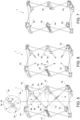
Figures 5 to 7 illustrate some steps for configuring the aerospace supporting frame from the deployed operating condition to the compacted operating condition; -
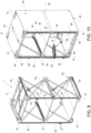
Figure 8 is a perspective view of the aerospace housing structure of the present invention; -
Figure 9 illustrates, in a perspective and exploded view, a further aerospace housing structure according to the dictates of the present invention; -
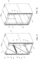
Figures 10 to 12 show different possible configurations of the aerospace housing structure inFigure 9 ; and -
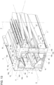
Figure 13 illustrates, on a larger scale, a detail ofFigure 2 . - In
Figures 1 and2 ,reference number 1 denotes an aerospace supporting frame, having a substantially parallelepiped shape and comprising a plurality ofrods frame 1, between a deployed operating condition (Fig. 1 ) and a compacted or folded operating condition (Fig. 2 ). - The
rods 2a are arranged to form twobases 3, which lie on planes spaced apart and substantially parallel to each other, and face each other along adirection 6 which, in the deployed condition during use, is vertical. In particular, as may be seen inFigure 1 , eachbase 3 consists of a pair ofrods 2a, which compriserespective ends 8a and respectiveintermediate portions 9a: theintermediate portions 9a are hinged to each other so as to form a cross. The hinge axes provided at theends 8a and theintermediate portions 9a are parallel to thedirection 6. Preferably, therods 2a have a fixed length and, in more detail, are straight. - At the same time, the
rods 2b are arranged on twosides 10 of the supportingframe 1. Thesides 10 lie on planes spaced apart and substantially parallel to each other, are connected to each other by therods 2a of thebases 3, and face each other along adirection 11, which is orthogonal to thedirection 6 and therefore, in the deployed condition during use, is horizontal. Therods 2b are similar to therods 2a, from a constructive point of view and from the point of view of mutual assembly. In particular, therods 2b are the same length as therods 2a. In the preferred example illustrated, for eachside 10, there are two pairs ofrods 2b, which thus form two crosses. In this case, as can be seen inFigure 1 , each of therods 2b comprises: - an
intermediate portion 9b hinged to anintermediate portion 9b of anotherrod 2b, - an
end 8b coupled in a rotating manner to anend 8a of one of therods 2a, and - an
end 10b coupled in a rotating manner to anend 10b of anotherrod 2b. - The hinge axes of the
rods 2b are parallel to thedirection 11. - Thanks to this hinging of the
rods 2a and therods 2b, there is a pantograph structure or leverage on eachside 10 and on each base 3: starting from the deployed condition, said pantograph leverages allow thebases 3 to approach each other along thedirection 6 and thesides 10 to approach each other along thedirection 11 relatively easily and quickly in order to switch to the compacted condition. In general, due to the manner in which the rods of theframe 1 are hinged, according to a preferred aspect of the present invention, by changing from the deployed condition to the compacted condition, the height of theframe 1 along the direction 6 (corresponding substantially to the distance between the bases 3) decreases from a value H1 to a value H2; the width of theframe 1 along the direction 11 (corresponding substantially to the distance between the sides 10) decreases from a value D1 to a value D2; and the length of thebases 10 and therefore of theframe 1 along adirection 12 orthogonal to thedirections - As mentioned above, this result is obtained by means of the
rods aforementioned rods rods direction 12 and are arranged along thesides 10. When therods rods rods rod - As shown in
Figure 1 , therods 2c are arranged substantially centrally between the bases 3 (in relation to the direction 6), while therods 2d are substantially coplanar to thebases 3, i.e. they are arranged at the edges of theframe 1, at virtual intersections between thebases 3 and thesides 10. - In particular, for each
side 10 there are tworods 2c, arranged in proximity, even if spaced apart along thedirection 6. On eachside 10, therods 2c comprise respective ends 8c that are carried by twocoupling elements 15 opposite each other and hinged to theends 10b of therods 2b. - Similarly, the
rods 2d compriserespective ends 8d that are carried by couplingelements 16, arranged at the eight vertices of theframe 1 and thus defining respective angle elements. Each of thecoupling elements 16 is hinged to one of theends 8a and to one of theends 8b, in addition to being coupled to one of theends 8d of therods 2d. - It is apparent from
Figure 1 that, in the deployed condition, thecoupling elements Figure 2 , at least some of theelements 15 and 16 (i.e. at least the elements 16) are arranged to be in contact against each other in the compacted condition, so as to form, together, a pair of supportingmembers 18, arranged at the opposite longitudinal ends of the frame 1 (along the direction 12). - In other words, the
elements - In the compacted condition, in fact, the
ends members 18, which effectively support the loads along thedirections - As seen in the detail of
Figure 13 , each of the supportingmembers 18 has a ring shape, and its nodes are arranged in series along this ring. In other words, each node is interposed between, and is in contact against, two adjacent nodes. Considering any pair of nodes that are adjacent along the ring path, the coupling mode for coupling these nodes defines at least two contact bearings directed along respective X and Y directions that are orthogonal to each other and are parallel, respectively, to thedirections support member 18 discharge the loads that are directed along thedirections - This coupling mode is explained in detail below, considering the specific solution illustrated by way of a non-limiting example.
- Each of the nodes defined by the
elements 16 is an angle node comprising abody 16a and aflap 16b, protruding cantilevered from thebody 16a along thedirection 12. Eachflap 16b comprises twostraight portions directions portions 16c are aligned with each other parallel to thedirection 11, and at least one of theportions 16c protrudes relative to thebody 16a of its node so as to couple to theportion 16c of the adjacent node. More particularly, thebodies 16a of two adjacent nodes are spaced apart from each other; at the same time, the end of one of the twoportions 16c forms aseat 16g, which has a step shape, is engaged by the end of theother portion 16c and is bounded by twoabutment shoulders other portion 16c. - As a result, the
flaps 16b define the contact coupling along both the directions X and Y, in the case of adjacent nodes both defined byelements 16. - Let's consider now the case in which the two adjacent nodes are defined by an
element 16 and anelement 15. In the illustrated case, theelement 15 comprises abody 15a and aflap 15b, which protrudes cantilevered from thebody 15a along thedirection 12 and is straight and parallel to thedirection 6. - The
flap 15b protrudes relative to thebody 15a parallel to thedirection 6 so as to couple to theportion 16d of the adjacent node, which is defined by the element 16 (according to variants not illustrated, theportion 16d protrudes from thebody 16a to couple to theflap 15b). - In particular, the end of the
flap 15b has anabutment shoulder 15e that is orthogonal to the direction X and is in contact against a corresponding shoulder of the end of theportion 16d. At the same time, thebody 15a has anabutment shoulder 15f that is orthogonal to the Y direction and is in contact against a corresponding shoulder of thebody 16a. - In this specific case, therefore, the contact bearings along the directions X and Y are defined, one, by the
flaps bodies - In addition to the contact bearings along the two directions X and Y, the adjacent nodes defined by the
elements direction 12. In the particular illustrated example, the end of theflap 15b has anabutment shoulder 15g in contact against thebody 16a of the adjacent node, along this direction Z (according to non-illustrated variants, it is the end of theportion 16d that is resting on thebody 15a). - In this way, the
elements - As can be seen in
Figure 3 , again in the compacted condition, the supportingmembers 18 can be wound bybelts 19 or similar extended elements, preferably flexible (ropes, cables, etc.), to retain theelements frame 1 from deploying autonomously and/or accidentally. In particular, an intermediate cover is placed between eachmember 18 and therelative belt 19. This intermediate cover is defined, for example, by two C-shaped half-shells, or by four covering elements, each of which has an angular shape and is coupled to arespective element 16 so as to cover the latter (while theelements 15 may remain uncovered). In particular, such covering elements are defined by thesame elements 48 that will be described below with reference toFigure 9 . - As shown in
Figure 4 , the compacted condition is used to launch theframe 1 into an orbiting space station 20 (partially illustrated). As mentioned above, the loads due to space launch are absorbed by the nodes defined by theelements members 18 in the compacted condition. - At the same time, the dimensions of the
frame 1 defined by the height value H2 and the width value D2 are extremely small, as explained above, so that theframe 1 can enter thestation 20 through its relativelysmall hatch 21. - With reference to
Figures 5 to 7 , considering the opposite longitudinal ends of theframe 1 along thedirection 12, preferably theframe 1 is without rods on one side (i.e. at the front end), while it comprises a plurality ofrods 2e on the other side (at the rear end) . Therods 2e comprise respective ends 8e that are coupled to thecoupling elements 15 and/or 16 by means of joints 22 (Fig. 6 ) that allow therods 2e to be arranged in a first position (Fig.5 ) or in a second position (Fig.7 ). - In particular, to allow the
joints 22 to be connected, theelements elements - In the first position, the
rods 2e lie on a plane orthogonal to thedirection 12 and are fixed together in a releasable manner by at least onefastening device 23. As shown in the enlarged area ofFigure 5 , for example, thedevice 23 comprises a lockingrod 24 that is coupled in a sliding manner to one of therods 2e to move to and from a locked position, wherein it is simultaneously fastened to the ends of fourrods 2e so as to hold them in a fixed position with respect to each other, thus forming a cross. - In this way, the
rods 2e perform a stiffening function for theframe 1 at the rear end in the deployed condition. - In the second position, on the other hand, the
rods 2e are uncoupled from each other and protrude cantilevered fromrespective coupling elements rods devices 23 must first be released to uncouple therods 2e from each other (Fig. 6 ), and then therods 2e must be rotated around thejoints 22 to arrange them in their second position (Fig. 7 ). After these operations, and after unlocking the extension of therods frame 1 in the compacted condition by bringing thecoupling elements rods rods 2d closer together along thedirections rods elements 16 come into contact with theelements 15 and, thus, form the two supportingmembers 18. In this compacted condition, as shown inFigure 2 , therods bases 3 andsides 10 of theframe 1 and define acavity 26 that is elongated along thedirection 12, houses therods 2e, and is open at the two opposite longitudinal ends of theframe 1. - In order to switch from the compacted condition to the deployed condition, the above operations are obviously performed in the reverse order.
- When the
frame 1 is arranged in its deployed condition, it is normally used to form ahousing structure 30, as shown inFigures 8 to 12 . - For this purpose, the
frame 1 is joined to at least one covering element, arranged along at least one of thebases 3 and/or sides 10. In the specific case ofFigure 8 , thestructure 30 is assembled by mounting, in a releasable manner, at least onerigid panel 32 in the space inside theframe 1. In particular, twohorizontal panels 32 are arranged to cover thebases 3, as floor and roof, while an additionalhorizontal panel 32 is coupled to theelements 15 in a fixed position, as an intermediate shelf. In this way, thestructure 30 defines a shelf that is partially open at the side and rear, as well as being fully open at the front to ensure access to its interior. - In addition, the
structure 30 comprises at least twouprights 34, which are parallel to thedirection 6, are arranged at the front ends ofsides 10 of theframe 1 and, in particular, are attached to theelements uprights 34 are provided with respective rows of fasteners orconnectors 27, which can be used as an alternative to each other to couple one or more components to theframe 1 in a desired position. - For example, the
connectors 27 of theuprights 34 can be used to couple ahook 35 to hang objects and/or asupport arm 36 for a keyboard or tray, at any height. - With reference to
Figures 9 and10 , in this configuration thestructure 30 comprises acanvas cover 40, which is arranged around theframe 1, as the outer covering of at least one of the bases 3 (the upper one), thesides 10, and the rear end of theframe 1. - Preferably, the
canvas 40 is tensioned when coupled to theframe 1, so as to form a tensile structure and further stiffen theframe 1, as with an umbrella. In this regard, advantageously, thecanvas 40 carriesbelt elements 41 and/orelastic elements 42 suitable for tensioning thecanvas 40 around theframe 1. As an alternative or in combination with theelements canvas 40 has elastic properties that allow it to be slightly smaller than the outer dimensions of theframe 1, at rest, and to extend slightly to be tensioned when placed around theframe 1. - In this configuration, thanks to the
canvas 40, the open shelf inFigure 8 becomes a closed structure along the entire periphery, except for afront opening 45 that allows users to access the internal space of the structure 30 (Fig. 10 ). Theopening 45 is defined laterally by twofrontal portions 47 of thecanvas 40. Theportions 47 partially cover theuprights 34 and theelements vertical eyelets 46 that allow access to theconnectors 27 of theuprights 34 and/or access to front connection portions forming part of theelements - The
canvas 40 has a parallelepiped shape, i.e. the same shape as theframe 1. Preferably, thecanvas 40 is supported by a plurality ofrigid angle elements 48, only some of which are visible inFigure 9 . In particular, theelements 48 are arranged at the vertices of thecanvas 40, preferably inside the latter. Theelements 48 are coupled in a releasable manner to the frame 1: in particular, they overlap theelements 16 and are fixed to the latter, for example by interlocking and/or by male-female type couplings and/or by additional fixing pins. - The eight
elements 48 are used not only to tension thecanvas 40 and/or to protect saidcanvas 40 from possible tears, which could be caused by the metal parts and/or protruding parts ofelements 16 of theframe 1, but are also used to define the intermediate cover between themembers 18 and therespective belts 19, when theframe 1 is in the compacted condition, as already mentioned above. As can be seen inFigure 3 , theelements 48 are preferably provided with respective loops, on an outer surface thereof, for the passage and fixing of thebelt 19. Moreover, advantageously, theelements 48 contribute to the alignment and interconnection between the nodes defined by the elements 16: in fact, in addition to being coupled to thecorresponding elements 16 that are covered, the fourelements 48 are coupled to each other at eachmember 18, two by two, by means of a coupling of the interlocking type and/or the male-female type. - Again, with reference to
Figure 10 , the housing structure 30 (configured as a shelf) further comprises a plurality of anechoic and/or insulatingpanels 49, arranged inside theframe 1 at thesides 10 and/or at the rear end, opposite theopening 45. Thepanels 49 are fixed to theframe 1 and/or to thecanvas 40 in a releasable manner, in a way not shown in detail, e.g. by means of Velcro stitched or glued to the inner surface of thecanvas 40. -
Figures 11 and 12 show how thehousing structure 30 can be configured as a living cell for a crew member of thestation 20 or as a radiation shelter, again for crew members. - In particular, in the configuration shown in
Figure 11 , thehousing structure 30 is withoutpanels 32, while thepanels 49 are also provided at thebases 3 and/or the rear end of theframe 1. In a manner not illustrated, thestructure 30 may also comprise covering elements arranged above therods 2c and/or 2d. - In the configuration of
Figure 12 , on the other hand, thehousing structure 30 comprises a plurality of anti-radiation panels 50 (defined, for example, by containers containing water) that are arranged inside theframe 1 and are attached directly or indirectly to the latter and/or to thecanvas 40 in a releasable manner, not illustrated in detail. For example, thepanels 50 overlap thepanels 49 and are attached to the latter by Velcro. - The
structure 30 further comprises a plurality of interfaces, not illustrated, of the electrical type (for signal transmission and/or power supply), of the sensor type, or of the hydraulic or pneumatic type. In this regard, in particular, thepanels canvas 40 are provided with pre-cut holes or pre-cut or pre-marked areas, not illustrated, in order to obtain openings that are arranged in various positions, defined in the design phase, and allowing, in use, the passage of ducts (air ventilation ducts) and/or wiring from the outside to the inside of thehousing structure 30. In combination or as an alternative to the possibility of obtaining such openings, thecanvas 40 bears one or more wirings, which are preferably arranged integrated in thecanvas 40 as weaving and/or sewing elements. - From the above, it ensues that the
frame 1, in addition to being deployable, is extremely light, thanks to the rods, but also has structural characteristics that allow it to support the loads that are present during space launches, in the compacted operating condition. - In fact, as far as load resistance is concerned, the
members 18 only form in the compacted condition and contribute to stiffening theframe 1 specifically during the space launch. In particular, theframe 1 is positioned so that the launch direction is orthogonal to thedirection 12, so that the rods (preferably made of carbon) are completely unloaded and the loads are supported only and exclusively by the nodes arranged, together, to form themembers 18. - At the same time, in the deployed operating condition, i.e. during normal use, the
members 18 are broken down intoseveral elements frame 1. In fact, in the deployed operating condition, structural rigidity is essentially conferred by therods frame 1 to be oversized as a whole, since they must withstand relatively low loads (corresponding to those of an accidental kick by a crew member, the so-called "crew kick load"). - At the same time, the
frame 1 has a high volume reduction in shifting from the deployed condition to the compacted condition. - As a result, on the one hand, in the deployed condition, the dimensions L1, D1, H1 can be set so as to meet the minimum size requirements required by regulations and/or agencies responsible for space programmes, with regard to the volume of living space inside the
structure 30. - On the other, thanks to the reduction obtained for the dimensions D2 and H2 in the compacted condition, the
frame 1 is able to pass through the small hatches provided in modern generation space stations. Again, in the compacted condition, theframe 1 is compatible with transport inside the bags already used today, with standard defined dimensions, without having to design dedicated transport containers. - In addition, in the deployed operating condition, the
frame 1 allows a liveable volume to be obtained quickly. The volume can be configured for different purposes, e.g. as a crew living cell, as a storage shelf, as a support shelf for components and equipment, as a work area, as a temporary radiation shelter, etc. Consequently, thestructure 30 is multifunctional or multi-purpose and is particularly suitable for inside space stations. In fact, all the coupling systems provided to connect the various components (directly or indirectly) to theframe 1 are of the releasable type, so that it is possible to assemble, disassemble, and modify the arrangement of these components quickly, with the aim of optimizing the space inside the space station according to the specific needs of the crew during the mission. - Lastly, it is clear from the foregoing that modifications and variations may be made to the
frame 1 described with reference to the appended figures, while remaining within the sphere of protection of the present invention, as defined in the appended claims. - In particular, the coupling mode between the nodes defined by the
elements members 18, in which each node is coupled in contact against two adjacent nodes, without having a hyperstatic structure, but in such a way as to transfer the loads in a reciprocal manner along the ring path.
Claims (13)
- An aerospace housing structure (30) comprising:- an aerospace supporting frame (1) comprising:a) a plurality of rods (2a, 2b, 2c, 2d) each comprising two opposite ends (8a,8b,10b,8c,8d); said rods being arranged so as to define two bases (3) substantially parallel and opposite each other, and two sides (10), which are substantially parallel and opposite each other and are coupled to each other by said bases (3);b) a plurality of joint nodes (15,16) that couple said ends in a mutually rotating manner so as to be able to configure said supporting frame (1) between a deployed operating condition and a compacted operating condition; said nodes (15,16) being spaced apart from one another in the deployed operating condition and each being hinged to at least two of said rods (2a,2b,2c,2d); in the compacted operating condition, each of said nodes being placed side by side with two adjacent nodes so as to form, together, two supporting members (18) arranged at opposite longitudinal ends of the supporting frame (1); wherein, in the compacted operating condition, each of said supporting members (10) is ring-shaped;- covering means (32,49,40), which are removably coupled to said supporting frame (1) when said supporting frame (1) is in the deployed condition and are arranged, at least, at one of said bases (3) and said sides (10); wherein said covering means comprise a canvas (40) arranged around said supporting frame (1) in the deployed condition.
- The aerospace housing structure according to claim 1, wherein said covering means comprise tensioning means (41, 42) for tensioning said canvas (40) around said supporting frame (1) when said canvas is coupled to said supporting frame (1).
- The aerospace housing structure according to claim 1 or 2, wherein said canvas (40) defines a closed structure along the entire periphery of said supporting frame, except for a front opening (45) that allows users to access the internal space of said aerospace housing structure (30).
- The aerospace housing structure according to anyone of the previous claims, wherein said covering means comprise rigid angle elements (48), which are arranged in fixed positions on said canvas (40) at respective vertices of the supporting frame (1) and are releasably coupled to said supporting frame (1), when said supporting frame is in the deployed condition.
- The aerospace housing structure according to claim 4, further comprising:- retention means (19) arranged around said supporting members (18) when said supporting frame (1) is in the compacted condition, so as to maintain said nodes in positions placed side by side to each other;- an intermediate cover suitable to be arranged between each of said supporting members (18) and the corresponding retention means, in the compacted condition;wherein said intermediate cover comprises said rigid angle elements (48).
- The aerospace housing structure according to anyone of the previous claims, further comprising at least two uprights (34), which are fixed to said supporting frame (1) when said supporting frame is in the deployed condition, said uprights being arranged orthogonally to said bases (3) and at said sides (10), and each comprising a row of connectors (27) that can be selected alternatively to one another to couple a component to said housing structure (30) .
- The aerospace housing structure according to anyone of the previous claims, wherein, when said supporting frame is the compacted condition, for any pair of adjacent nodes along the ring path, the two nodes of said pair are coupled to each other so as to define at least two contact bearings along directions (X,Y) that are orthogonal to each other.
- The aerospace housing structure according to claim 7, wherein, in the compacted operating condition, the nodes of each supporting member (18) are arranged in series along the ring path, so that each node is interposed between, and is in contact against, two adjacent nodes.
- The aerospace housing structure according to any of claims 7 to 8, wherein said rods (2a,2b,2c,2d), on each of said sides (10) and on each of said bases (3), form a pantograph structure.
- The aerospace housing structure according to claim 9, wherein, in the deployed operating condition, said sides (10) have a first length (L1) and are spaced apart from each other by a first width (D1) and said bases (3) are spaced apart from each other by a first height (H1); and, in the compacted operating condition, said sides (10) have a second length (L2) and are spaced apart from each other by a second width (D2) and said bases (3) are spaced apart from each other by a second height (H2); said first height (H1) and first width (D1) being greater, respectively, than said second height (H2) and second width (D2), and said first length (L1) being smaller than said second length (L2) .
- The aerospace housing structure according to claim 10, wherein said rods comprise, for each said side (10):- two pairs of first rods (2b), the two rods of each pair having a fixed length and comprising respective intermediate portions (9b) hinged to each other; and- second rods (2c,2d) that are parallel and/or coplanar to said bases (3) and have an adjustable length between at least two values, corresponding to said first length (L1) and respectively to said second length (L2).
- The aerospace housing structure according to claim 11, wherein said rods comprise, for each said base (3), a single pair of third rods (2a) having a fixed length and comprising respective intermediate portions (9a) hinged to each other.
- The aerospace housing structure according to any one of the claims 9 to 12, further comprising additional rods (2e) that, in the deployed operating condition, are arranged at one of said longitudinal ends; said additional rods (2e) comprising respective ends (8e) that are coupled to said nodes in a rotating manner, so that they can be folded into a storage position, in which they are parallel to said bases (3) and to said sides (10).
Applications Claiming Priority (3)
| Application Number | Priority Date | Filing Date | Title |
|---|---|---|---|
| IT102018000010818A IT201800010818A1 (en) | 2018-12-05 | 2018-12-05 | EXTENDABLE SUPPORT FRAME, AND HOUSING STRUCTURE PROVIDED WITH SUCH SUPPORT FRAME, ESPECIALLY FOR AEROSPACE APPLICATIONS |
| IT102018000010824A IT201800010824A1 (en) | 2018-12-05 | 2018-12-05 | EXTENDABLE SUPPORT FRAME, AND HOUSING STRUCTURE PROVIDED WITH SUCH SUPPORT FRAME, ESPECIALLY FOR AEROSPACE APPLICATIONS |
| PCT/IB2019/060485 WO2020115701A1 (en) | 2018-12-05 | 2019-12-05 | Deployable supporting frame, and housing structure provided with such supporting frame, in particular for aerospace applications |
Publications (2)
| Publication Number | Publication Date |
|---|---|
| EP3891069A1 EP3891069A1 (en) | 2021-10-13 |
| EP3891069B1 true EP3891069B1 (en) | 2023-10-11 |
Family
ID=69158145
Family Applications (1)
| Application Number | Title | Priority Date | Filing Date |
|---|---|---|---|
| EP19835483.9A Active EP3891069B1 (en) | 2018-12-05 | 2019-12-05 | Housing structure provided with a deployable supporting frame. for aerospace applications |
Country Status (5)
| Country | Link |
|---|---|
| US (1) | US11958639B2 (en) |
| EP (1) | EP3891069B1 (en) |
| ES (1) | ES2963427T3 (en) |
| PL (1) | PL3891069T3 (en) |
| WO (1) | WO2020115701A1 (en) |
Families Citing this family (4)
| Publication number | Priority date | Publication date | Assignee | Title |
|---|---|---|---|---|
| IT201900019322A1 (en) * | 2019-10-18 | 2021-04-18 | Thales Alenia Space Italia Spa Con Unico Socio | END-TO-END ASSISTANCE IN ORBIT |
| US12448153B2 (en) * | 2021-03-31 | 2025-10-21 | Roccor, Llc | Rigid articulated batten integrated truss devices, systems, and methods |
| CN113895659B (en) * | 2021-11-25 | 2023-09-19 | 苏州馥昶空间技术有限公司 | Solar wing opening device |
| CN116039954A (en) * | 2023-01-14 | 2023-05-02 | 哈尔滨工业大学(深圳) | Single-degree-of-freedom planar two-dimensional expandable basic unit and large-scale expandable device |
Family Cites Families (11)
| Publication number | Priority date | Publication date | Assignee | Title |
|---|---|---|---|---|
| US5016418A (en) | 1986-08-22 | 1991-05-21 | The United States Of America As Represented By The Administrator Of The National Aeronautics And Space Administration | Synchronously deployable double fold beam and planar truss structure |
| US5244001A (en) | 1991-01-04 | 1993-09-14 | Lynch James P | Collapsible canopy framework having captured scissor ends with non-compressive pivots |
| US5327700A (en) | 1991-12-05 | 1994-07-12 | Skyline Displays, Inc. | Collapsible modular display tower assembly |
| JPH05221392A (en) | 1992-02-12 | 1993-08-31 | Uchu Tsushin Kiso Gijutsu Kenkyusho:Kk | Deployable truss structure |
| US5243718A (en) * | 1992-04-14 | 1993-09-14 | Louis Shamie | Foldable playpen |
| TW499019U (en) * | 2001-08-03 | 2002-08-11 | Yi-Ching Guo | Improved connecting and drawing structure of a frame |
| WO2005111343A1 (en) | 2004-05-13 | 2005-11-24 | National University Of Singapore | Deployable structure |
| US8464493B2 (en) * | 2008-03-03 | 2013-06-18 | The United States Of America As Represented By The Secretary Of The Army | Transportable modular configuration for holding panels |
| US10024050B2 (en) * | 2011-12-07 | 2018-07-17 | Cpi Technologies, Llc | Solar panel truss deployable from moving carrier |
| CN206050100U (en) | 2016-08-31 | 2017-03-29 | 燕山大学 | Torsion spring drives scissor-type extending arm |
| US10207826B2 (en) * | 2016-10-12 | 2019-02-19 | The Boeing Company | Artificial gravity system with a unibody rotating structure that rotates about a stationary structure |
-
2019
- 2019-12-05 WO PCT/IB2019/060485 patent/WO2020115701A1/en not_active Ceased
- 2019-12-05 PL PL19835483.9T patent/PL3891069T3/en unknown
- 2019-12-05 EP EP19835483.9A patent/EP3891069B1/en active Active
- 2019-12-05 US US17/311,235 patent/US11958639B2/en active Active
- 2019-12-05 ES ES19835483T patent/ES2963427T3/en active Active
Also Published As
| Publication number | Publication date |
|---|---|
| WO2020115701A1 (en) | 2020-06-11 |
| US11958639B2 (en) | 2024-04-16 |
| US20220017241A1 (en) | 2022-01-20 |
| EP3891069A1 (en) | 2021-10-13 |
| PL3891069T3 (en) | 2024-03-11 |
| ES2963427T3 (en) | 2024-03-27 |
Similar Documents
| Publication | Publication Date | Title |
|---|---|---|
| EP3891069B1 (en) | Housing structure provided with a deployable supporting frame. for aerospace applications | |
| US5016418A (en) | Synchronously deployable double fold beam and planar truss structure | |
| JP5694306B2 (en) | Telescopic structure | |
| US10734941B2 (en) | Compact, self-deploying structures and methods for deploying foldable, structural origami arrays using a compression column | |
| US6637702B1 (en) | Nested beam deployable solar array | |
| US6016999A (en) | Spacecraft platforms | |
| US3435570A (en) | Erectable structure with scissors link | |
| CA2889812C (en) | Large deployable reflector for a satellite antenna | |
| US8894017B1 (en) | Flexible array support structure | |
| US4765114A (en) | Expandable pallet for space station interface attachments | |
| EP2498334B1 (en) | Deployable flat panel array | |
| CN109850185B (en) | Satellite structure for loading deployable antenna and multiple optical cameras | |
| EP4012837B1 (en) | Satellite antenna having pantographic trusses and associated methods | |
| KR101129345B1 (en) | Weightlessness offering apparatus for deployment test of solar panel | |
| US8872042B2 (en) | Methods and systems for providing inflatable lightweight shielded enclosures | |
| US4805368A (en) | Expandable pallet for space station interface attachments | |
| US20090199503A1 (en) | Deployable structures | |
| US5184789A (en) | Space station facility | |
| US12448153B2 (en) | Rigid articulated batten integrated truss devices, systems, and methods | |
| CN206655540U (en) | A kind of expansible rapid deployment break camp of general large span | |
| IT201800010824A1 (en) | EXTENDABLE SUPPORT FRAME, AND HOUSING STRUCTURE PROVIDED WITH SUCH SUPPORT FRAME, ESPECIALLY FOR AEROSPACE APPLICATIONS | |
| IT201800010818A1 (en) | EXTENDABLE SUPPORT FRAME, AND HOUSING STRUCTURE PROVIDED WITH SUCH SUPPORT FRAME, ESPECIALLY FOR AEROSPACE APPLICATIONS | |
| KR20250066087A (en) | Foldable chair and aircraft including the same | |
| CN116995400A (en) | A deployment mechanism for a multi-fold array deployment antenna and a satellite | |
| RU2167789C1 (en) | Transformable structure |
Legal Events
| Date | Code | Title | Description |
|---|---|---|---|
| STAA | Information on the status of an ep patent application or granted ep patent |
Free format text: STATUS: UNKNOWN |
|
| STAA | Information on the status of an ep patent application or granted ep patent |
Free format text: STATUS: THE INTERNATIONAL PUBLICATION HAS BEEN MADE |
|
| PUAI | Public reference made under article 153(3) epc to a published international application that has entered the european phase |
Free format text: ORIGINAL CODE: 0009012 |
|
| STAA | Information on the status of an ep patent application or granted ep patent |
Free format text: STATUS: REQUEST FOR EXAMINATION WAS MADE |
|
| 17P | Request for examination filed |
Effective date: 20210617 |
|
| AK | Designated contracting states |
Kind code of ref document: A1 Designated state(s): AL AT BE BG CH CY CZ DE DK EE ES FI FR GB GR HR HU IE IS IT LI LT LU LV MC MK MT NL NO PL PT RO RS SE SI SK SM TR |
|
| DAV | Request for validation of the european patent (deleted) | ||
| DAX | Request for extension of the european patent (deleted) | ||
| GRAP | Despatch of communication of intention to grant a patent |
Free format text: ORIGINAL CODE: EPIDOSNIGR1 |
|
| STAA | Information on the status of an ep patent application or granted ep patent |
Free format text: STATUS: GRANT OF PATENT IS INTENDED |
|
| INTG | Intention to grant announced |
Effective date: 20221208 |
|
| GRAJ | Information related to disapproval of communication of intention to grant by the applicant or resumption of examination proceedings by the epo deleted |
Free format text: ORIGINAL CODE: EPIDOSDIGR1 |
|
| STAA | Information on the status of an ep patent application or granted ep patent |
Free format text: STATUS: REQUEST FOR EXAMINATION WAS MADE |
|
| GRAP | Despatch of communication of intention to grant a patent |
Free format text: ORIGINAL CODE: EPIDOSNIGR1 |
|
| STAA | Information on the status of an ep patent application or granted ep patent |
Free format text: STATUS: GRANT OF PATENT IS INTENDED |
|
| INTC | Intention to grant announced (deleted) | ||
| INTG | Intention to grant announced |
Effective date: 20230502 |
|
| P01 | Opt-out of the competence of the unified patent court (upc) registered |
Effective date: 20230518 |
|
| GRAS | Grant fee paid |
Free format text: ORIGINAL CODE: EPIDOSNIGR3 |
|
| GRAA | (expected) grant |
Free format text: ORIGINAL CODE: 0009210 |
|
| STAA | Information on the status of an ep patent application or granted ep patent |
Free format text: STATUS: THE PATENT HAS BEEN GRANTED |
|
| AK | Designated contracting states |
Kind code of ref document: B1 Designated state(s): AL AT BE BG CH CY CZ DE DK EE ES FI FR GB GR HR HU IE IS IT LI LT LU LV MC MK MT NL NO PL PT RO RS SE SI SK SM TR |
|
| REG | Reference to a national code |
Ref country code: GB Ref legal event code: FG4D |
|
| REG | Reference to a national code |
Ref country code: CH Ref legal event code: EP |
|
| REG | Reference to a national code |
Ref country code: DE Ref legal event code: R096 Ref document number: 602019039301 Country of ref document: DE |
|
| REG | Reference to a national code |
Ref country code: IE Ref legal event code: FG4D |
|
| REG | Reference to a national code |
Ref country code: NL Ref legal event code: FP |
|
| REG | Reference to a national code |
Ref country code: LT Ref legal event code: MG9D |
|
| REG | Reference to a national code |
Ref country code: AT Ref legal event code: MK05 Ref document number: 1620001 Country of ref document: AT Kind code of ref document: T Effective date: 20231011 |
|
| REG | Reference to a national code |
Ref country code: ES Ref legal event code: FG2A Ref document number: 2963427 Country of ref document: ES Kind code of ref document: T3 Effective date: 20240327 |
|
| PG25 | Lapsed in a contracting state [announced via postgrant information from national office to epo] |
Ref country code: GR Free format text: LAPSE BECAUSE OF FAILURE TO SUBMIT A TRANSLATION OF THE DESCRIPTION OR TO PAY THE FEE WITHIN THE PRESCRIBED TIME-LIMIT Effective date: 20240112 |
|
| PG25 | Lapsed in a contracting state [announced via postgrant information from national office to epo] |
Ref country code: IS Free format text: LAPSE BECAUSE OF FAILURE TO SUBMIT A TRANSLATION OF THE DESCRIPTION OR TO PAY THE FEE WITHIN THE PRESCRIBED TIME-LIMIT Effective date: 20240211 |
|
| PG25 | Lapsed in a contracting state [announced via postgrant information from national office to epo] |
Ref country code: LT Free format text: LAPSE BECAUSE OF FAILURE TO SUBMIT A TRANSLATION OF THE DESCRIPTION OR TO PAY THE FEE WITHIN THE PRESCRIBED TIME-LIMIT Effective date: 20231011 |
|
| PG25 | Lapsed in a contracting state [announced via postgrant information from national office to epo] |
Ref country code: AT Free format text: LAPSE BECAUSE OF FAILURE TO SUBMIT A TRANSLATION OF THE DESCRIPTION OR TO PAY THE FEE WITHIN THE PRESCRIBED TIME-LIMIT Effective date: 20231011 |
|
| PG25 | Lapsed in a contracting state [announced via postgrant information from national office to epo] |
Ref country code: LT Free format text: LAPSE BECAUSE OF FAILURE TO SUBMIT A TRANSLATION OF THE DESCRIPTION OR TO PAY THE FEE WITHIN THE PRESCRIBED TIME-LIMIT Effective date: 20231011 Ref country code: IS Free format text: LAPSE BECAUSE OF FAILURE TO SUBMIT A TRANSLATION OF THE DESCRIPTION OR TO PAY THE FEE WITHIN THE PRESCRIBED TIME-LIMIT Effective date: 20240211 Ref country code: GR Free format text: LAPSE BECAUSE OF FAILURE TO SUBMIT A TRANSLATION OF THE DESCRIPTION OR TO PAY THE FEE WITHIN THE PRESCRIBED TIME-LIMIT Effective date: 20240112 Ref country code: BG Free format text: LAPSE BECAUSE OF FAILURE TO SUBMIT A TRANSLATION OF THE DESCRIPTION OR TO PAY THE FEE WITHIN THE PRESCRIBED TIME-LIMIT Effective date: 20240111 Ref country code: AT Free format text: LAPSE BECAUSE OF FAILURE TO SUBMIT A TRANSLATION OF THE DESCRIPTION OR TO PAY THE FEE WITHIN THE PRESCRIBED TIME-LIMIT Effective date: 20231011 Ref country code: PT Free format text: LAPSE BECAUSE OF FAILURE TO SUBMIT A TRANSLATION OF THE DESCRIPTION OR TO PAY THE FEE WITHIN THE PRESCRIBED TIME-LIMIT Effective date: 20240212 |
|
| PG25 | Lapsed in a contracting state [announced via postgrant information from national office to epo] |
Ref country code: SE Free format text: LAPSE BECAUSE OF FAILURE TO SUBMIT A TRANSLATION OF THE DESCRIPTION OR TO PAY THE FEE WITHIN THE PRESCRIBED TIME-LIMIT Effective date: 20231011 Ref country code: RS Free format text: LAPSE BECAUSE OF FAILURE TO SUBMIT A TRANSLATION OF THE DESCRIPTION OR TO PAY THE FEE WITHIN THE PRESCRIBED TIME-LIMIT Effective date: 20231011 Ref country code: NO Free format text: LAPSE BECAUSE OF FAILURE TO SUBMIT A TRANSLATION OF THE DESCRIPTION OR TO PAY THE FEE WITHIN THE PRESCRIBED TIME-LIMIT Effective date: 20240111 Ref country code: LV Free format text: LAPSE BECAUSE OF FAILURE TO SUBMIT A TRANSLATION OF THE DESCRIPTION OR TO PAY THE FEE WITHIN THE PRESCRIBED TIME-LIMIT Effective date: 20231011 Ref country code: HR Free format text: LAPSE BECAUSE OF FAILURE TO SUBMIT A TRANSLATION OF THE DESCRIPTION OR TO PAY THE FEE WITHIN THE PRESCRIBED TIME-LIMIT Effective date: 20231011 |
|
| PG25 | Lapsed in a contracting state [announced via postgrant information from national office to epo] |
Ref country code: DK Free format text: LAPSE BECAUSE OF FAILURE TO SUBMIT A TRANSLATION OF THE DESCRIPTION OR TO PAY THE FEE WITHIN THE PRESCRIBED TIME-LIMIT Effective date: 20231011 |
|
| REG | Reference to a national code |
Ref country code: DE Ref legal event code: R097 Ref document number: 602019039301 Country of ref document: DE |
|
| PG25 | Lapsed in a contracting state [announced via postgrant information from national office to epo] |
Ref country code: CZ Free format text: LAPSE BECAUSE OF FAILURE TO SUBMIT A TRANSLATION OF THE DESCRIPTION OR TO PAY THE FEE WITHIN THE PRESCRIBED TIME-LIMIT Effective date: 20231011 |
|
| PG25 | Lapsed in a contracting state [announced via postgrant information from national office to epo] |
Ref country code: SK Free format text: LAPSE BECAUSE OF FAILURE TO SUBMIT A TRANSLATION OF THE DESCRIPTION OR TO PAY THE FEE WITHIN THE PRESCRIBED TIME-LIMIT Effective date: 20231011 |
|
| PG25 | Lapsed in a contracting state [announced via postgrant information from national office to epo] |
Ref country code: SM Free format text: LAPSE BECAUSE OF FAILURE TO SUBMIT A TRANSLATION OF THE DESCRIPTION OR TO PAY THE FEE WITHIN THE PRESCRIBED TIME-LIMIT Effective date: 20231011 Ref country code: SK Free format text: LAPSE BECAUSE OF FAILURE TO SUBMIT A TRANSLATION OF THE DESCRIPTION OR TO PAY THE FEE WITHIN THE PRESCRIBED TIME-LIMIT Effective date: 20231011 Ref country code: RO Free format text: LAPSE BECAUSE OF FAILURE TO SUBMIT A TRANSLATION OF THE DESCRIPTION OR TO PAY THE FEE WITHIN THE PRESCRIBED TIME-LIMIT Effective date: 20231011 Ref country code: EE Free format text: LAPSE BECAUSE OF FAILURE TO SUBMIT A TRANSLATION OF THE DESCRIPTION OR TO PAY THE FEE WITHIN THE PRESCRIBED TIME-LIMIT Effective date: 20231011 Ref country code: DK Free format text: LAPSE BECAUSE OF FAILURE TO SUBMIT A TRANSLATION OF THE DESCRIPTION OR TO PAY THE FEE WITHIN THE PRESCRIBED TIME-LIMIT Effective date: 20231011 Ref country code: CZ Free format text: LAPSE BECAUSE OF FAILURE TO SUBMIT A TRANSLATION OF THE DESCRIPTION OR TO PAY THE FEE WITHIN THE PRESCRIBED TIME-LIMIT Effective date: 20231011 |
|
| PLBE | No opposition filed within time limit |
Free format text: ORIGINAL CODE: 0009261 |
|
| STAA | Information on the status of an ep patent application or granted ep patent |
Free format text: STATUS: NO OPPOSITION FILED WITHIN TIME LIMIT |
|
| PG25 | Lapsed in a contracting state [announced via postgrant information from national office to epo] |
Ref country code: LU Free format text: LAPSE BECAUSE OF NON-PAYMENT OF DUE FEES Effective date: 20231205 |
|
| PG25 | Lapsed in a contracting state [announced via postgrant information from national office to epo] |
Ref country code: MC Free format text: LAPSE BECAUSE OF FAILURE TO SUBMIT A TRANSLATION OF THE DESCRIPTION OR TO PAY THE FEE WITHIN THE PRESCRIBED TIME-LIMIT Effective date: 20231011 |
|
| PG25 | Lapsed in a contracting state [announced via postgrant information from national office to epo] |
Ref country code: MC Free format text: LAPSE BECAUSE OF FAILURE TO SUBMIT A TRANSLATION OF THE DESCRIPTION OR TO PAY THE FEE WITHIN THE PRESCRIBED TIME-LIMIT Effective date: 20231011 Ref country code: LU Free format text: LAPSE BECAUSE OF NON-PAYMENT OF DUE FEES Effective date: 20231205 |
|
| 26N | No opposition filed |
Effective date: 20240712 |
|
| REG | Reference to a national code |
Ref country code: IE Ref legal event code: MM4A |
|
| PG25 | Lapsed in a contracting state [announced via postgrant information from national office to epo] |
Ref country code: IE Free format text: LAPSE BECAUSE OF NON-PAYMENT OF DUE FEES Effective date: 20231205 |
|
| PG25 | Lapsed in a contracting state [announced via postgrant information from national office to epo] |
Ref country code: SI Free format text: LAPSE BECAUSE OF FAILURE TO SUBMIT A TRANSLATION OF THE DESCRIPTION OR TO PAY THE FEE WITHIN THE PRESCRIBED TIME-LIMIT Effective date: 20231011 |
|
| PG25 | Lapsed in a contracting state [announced via postgrant information from national office to epo] |
Ref country code: SI Free format text: LAPSE BECAUSE OF FAILURE TO SUBMIT A TRANSLATION OF THE DESCRIPTION OR TO PAY THE FEE WITHIN THE PRESCRIBED TIME-LIMIT Effective date: 20231011 Ref country code: IE Free format text: LAPSE BECAUSE OF NON-PAYMENT OF DUE FEES Effective date: 20231205 |
|
| PGFP | Annual fee paid to national office [announced via postgrant information from national office to epo] |
Ref country code: CH Payment date: 20250101 Year of fee payment: 6 |
|
| PG25 | Lapsed in a contracting state [announced via postgrant information from national office to epo] |
Ref country code: FI Free format text: LAPSE BECAUSE OF FAILURE TO SUBMIT A TRANSLATION OF THE DESCRIPTION OR TO PAY THE FEE WITHIN THE PRESCRIBED TIME-LIMIT Effective date: 20231011 |
|
| PG25 | Lapsed in a contracting state [announced via postgrant information from national office to epo] |
Ref country code: CY Free format text: LAPSE BECAUSE OF FAILURE TO SUBMIT A TRANSLATION OF THE DESCRIPTION OR TO PAY THE FEE WITHIN THE PRESCRIBED TIME-LIMIT; INVALID AB INITIO Effective date: 20191205 |
|
| PG25 | Lapsed in a contracting state [announced via postgrant information from national office to epo] |
Ref country code: HU Free format text: LAPSE BECAUSE OF FAILURE TO SUBMIT A TRANSLATION OF THE DESCRIPTION OR TO PAY THE FEE WITHIN THE PRESCRIBED TIME-LIMIT; INVALID AB INITIO Effective date: 20191205 |
|
| PG25 | Lapsed in a contracting state [announced via postgrant information from national office to epo] |
Ref country code: TR Free format text: LAPSE BECAUSE OF FAILURE TO SUBMIT A TRANSLATION OF THE DESCRIPTION OR TO PAY THE FEE WITHIN THE PRESCRIBED TIME-LIMIT Effective date: 20231011 |
|
| REG | Reference to a national code |
Ref country code: CH Ref legal event code: U11 Free format text: ST27 STATUS EVENT CODE: U-0-0-U10-U11 (AS PROVIDED BY THE NATIONAL OFFICE) Effective date: 20260101 |
|
| PGFP | Annual fee paid to national office [announced via postgrant information from national office to epo] |
Ref country code: GB Payment date: 20251223 Year of fee payment: 7 |
|
| PGFP | Annual fee paid to national office [announced via postgrant information from national office to epo] |
Ref country code: IT Payment date: 20251117 Year of fee payment: 7 |
|
| PGFP | Annual fee paid to national office [announced via postgrant information from national office to epo] |
Ref country code: FR Payment date: 20251223 Year of fee payment: 7 Ref country code: NL Payment date: 20251222 Year of fee payment: 7 |
|
| PGFP | Annual fee paid to national office [announced via postgrant information from national office to epo] |
Ref country code: BE Payment date: 20251231 Year of fee payment: 7 |
|
| PGFP | Annual fee paid to national office [announced via postgrant information from national office to epo] |
Ref country code: PL Payment date: 20251110 Year of fee payment: 7 |
|
| PGFP | Annual fee paid to national office [announced via postgrant information from national office to epo] |
Ref country code: ES Payment date: 20260122 Year of fee payment: 7 |
|
| PGFP | Annual fee paid to national office [announced via postgrant information from national office to epo] |
Ref country code: DE Payment date: 20251229 Year of fee payment: 7 |