EP3890540B1 - Helmet with accessory attachment rail - Google Patents
Helmet with accessory attachment rail Download PDFInfo
- Publication number
- EP3890540B1 EP3890540B1 EP19891778.3A EP19891778A EP3890540B1 EP 3890540 B1 EP3890540 B1 EP 3890540B1 EP 19891778 A EP19891778 A EP 19891778A EP 3890540 B1 EP3890540 B1 EP 3890540B1
- Authority
- EP
- European Patent Office
- Prior art keywords
- helmet
- accessory
- attachment rail
- slot
- protective
- Prior art date
- Legal status (The legal status is an assumption and is not a legal conclusion. Google has not performed a legal analysis and makes no representation as to the accuracy of the status listed.)
- Active
Links
Images







Classifications
-
- A—HUMAN NECESSITIES
- A42—HEADWEAR
- A42B—HATS; HEAD COVERINGS
- A42B3/00—Helmets; Helmet covers ; Other protective head coverings
- A42B3/04—Parts, details or accessories of helmets
- A42B3/18—Face protection devices
- A42B3/185—Securing goggles or spectacles on helmet shells
-
- A—HUMAN NECESSITIES
- A42—HEADWEAR
- A42B—HATS; HEAD COVERINGS
- A42B3/00—Helmets; Helmet covers ; Other protective head coverings
- A42B3/04—Parts, details or accessories of helmets
-
- A—HUMAN NECESSITIES
- A42—HEADWEAR
- A42B—HATS; HEAD COVERINGS
- A42B3/00—Helmets; Helmet covers ; Other protective head coverings
- A42B3/04—Parts, details or accessories of helmets
- A42B3/0406—Accessories for helmets
-
- A—HUMAN NECESSITIES
- A42—HEADWEAR
- A42B—HATS; HEAD COVERINGS
- A42B3/00—Helmets; Helmet covers ; Other protective head coverings
- A42B3/04—Parts, details or accessories of helmets
- A42B3/16—Ear protection devices
-
- A—HUMAN NECESSITIES
- A42—HEADWEAR
- A42B—HATS; HEAD COVERINGS
- A42B3/00—Helmets; Helmet covers ; Other protective head coverings
- A42B3/04—Parts, details or accessories of helmets
- A42B3/18—Face protection devices
- A42B3/22—Visors
- A42B3/221—Attaching visors to helmet shells, e.g. on motorcycle helmets
-
- A—HUMAN NECESSITIES
- A42—HEADWEAR
- A42B—HATS; HEAD COVERINGS
- A42B3/00—Helmets; Helmet covers ; Other protective head coverings
- A42B3/04—Parts, details or accessories of helmets
- A42B3/18—Face protection devices
- A42B3/22—Visors
- A42B3/221—Attaching visors to helmet shells, e.g. on motorcycle helmets
- A42B3/222—Attaching visors to helmet shells, e.g. on motorcycle helmets in an articulated manner, e.g. hinge devices
Definitions
- the present invention relates generally to helmets for use in various situations and environments, and in particular to a protective helmet having an accessory attachment rail configured for removably attaching one or more accessories to the protective helmet.
- a protective helmet typically includes a hard shell for protecting the head of the user.
- One or more accessories may be removably or non-removably attached to the outer surface of the hard shell of the protective helmet.
- the one or more accessories may be configured to provide additional protection to the user, such as hearing or face protection.
- the one or more accessories may provide additional capability, such as providing additional visibility.
- the one or more accessories may be movable between a first, active position and a second, inactive position. For example, in the first position, the one or more accessories may provide the desired additional protection by, for example, extending in front of the user's face or over the user's ears. In the second, inactive position, the one or more accessories can be moved away from the user's face or ears when the circumstances do not require the additional protection or when the user desires to remove the protective helmet.
- the system for attaching the one more accessories has several disadvantages and requires improvement.
- the protective helmet has a slot that is formed on its outer surface such that each accessory that is added to the helmet must be installed in the same slot.
- the protective helmet has a through hole extending through the material of the hard shell, with each accessory being secured to the protective helmet by a fastener extending through the hole.
- installation and removal of accessories are complicated because they require removing the protective helmet, thereby compromising the user's safety if such installation or removal is done in the field.
- existing arrangements for attaching accessories to the protective helmet generally include many different pieces that can be easily lost during installation and removal, which complicates the assembly process and increases the risk of incorrect assembly.
- Another disadvantage of existing attachment designs is that they can compromise electrical protection of the helmet depending on the location of the attachment mechanism.
- WO 2006/114515 A1 discloses a device for removably fixing an illuminating lamp to a protective helmet. It is proposed that the lamp comprises a hooking pin forming a shoe intended to slide between two slide guides integral with a support of the helmet. The support comprises at least one abutment arranged at an end of the slide and intended to block the shoe in an extreme hook position.
- US 2017/0089554 A1 discloses a helmet assembly.
- the assembly is attached to the helmet and includes a light, a clip and a bracket.
- the light includes at least one engaging member configured to engage at least one engaging member on the clip and the clip is configured to attach to the bracket with a fastener.
- a safety helmet attachment and method for shielding eyes is known from US 6,892,393 B1 .
- An eye shield attachment has right and left structures adapted to be suspended below a rim of the helmet.
- At least one tongue of the eye shield attachment is adapted to be removably and dependently attached to rim slots in the helmet for supporting a side frame.
- the disclosure of WO 2018/169984 A1 is directed to a mounting rail assembly.
- the assembly comprises a rail to be configured to be coupled to a helmet wherein the rail has a mounting groove extending along a length along a front surface.
- the mounting groove is configured to be coupled to a first accessory device at two or more positions along a length of a rail.
- an improved protective helmet that addresses certain drawbacks and deficiencies associated with existing protective helmets.
- an improved protective helmet that can be easily and effectively worn by the user in a variety of environments while allowing for easy attachment, use, and removal of a variety of accessories to the protective helmet at the same time without the need to remove the protective helmet from the user's head.
- a protective helmet with an accessory attachment rail that addresses and/or overcomes some or all of the drawbacks associated with existing protective helmets configured for attaching one or more accessories to the protective helmet.
- an improved protective helmet that can be easily and effectively worn by the user in a variety of environments while allowing for easy attachment, use, and removal of a variety of accessories to the protective helmet without the need to remove the protective helmet from the user's head.
- a protective helmet according to claim 1 is provided.
- an accessory attachment rail has a body having a front end, a rear end, and two or more slots between the front end and the rear end. Each of the two or more slots are configured for removably receiving at least one helmet accessory.
- the accessory attachment rail further has a locking mechanism associated with each of the two or more slots for automatically locking the at least one helmet accessory in the two or more slots upon insertion of the at least one helmet accessory within the two or more slots and for preventing removal of the at least one helmet accessory from the two or more slots until the locking mechanism is unlocked.
- the accessory attachment rail further has at least one connection element for connecting the accessory attachment rail to an outer shell of the helmet.
- the locking mechanism of the accessory attachment rail may have a locking beam having a first end connected to at least a portion of the slot and a second free end movable relative to the first end in a direction toward an outer surface of the helmet when deflected by the at least one helmet accessory during insertion of the at least one helmet accessory into the one or more slots.
- the second free end of the locking beam may have a locking tab configured for engaging a corresponding locking slot on the at least one helmet accessory when the at least one helmet accessory is fully inserted into the two or more slots.
- the locking tab may have a tapered leading surface that is angled toward an open end of the two or more slots.
- the at least one connection element of the accessory attachment rail may be a plurality of deflectable tabs spaced around an inner surface of the accessory attachment rail facing an outer surface of the outer shell.
- Each of the plurality of deflectable tabs may be configured for insertion into an opening formed on the outer shell.
- Each of the plurality of deflectable tabs may have a first end connected to the body of the accessory attachment rail and a second end protruding relative to the first end in a direction away from the inner surface and toward an outer surface of the outer shell.
- Each deflectable tab may have a lip for engaging a corresponding ledge on the outer shell.
- ranges or ratios disclosed herein are to be understood to encompass the beginning and ending values and any and all subranges or subratios subsumed therein.
- a stated range or ratio of "1 to 10" should be considered to include any and all subranges or subratios between (and inclusive of) the minimum value of 1 and the maximum value of 10; that is, all subranges or subratios beginning with a minimum value of 1 or more and ending with a maximum value of 10 or less.
- the ranges and/or ratios disclosed herein represent the average values over the specified range and/or ratio.
- At least one of is synonymous with “one or more of”.
- the phrase “at least one of A, B, and C” means any one of A, B, or C, or any combination of any two or more of A, B, or C.
- "at least one of A, B, and C” includes A alone; or B alone; or C alone; or A and B; or A and C; or B and C; or all of A, B, and C.
- adjacent means proximate to but not in direct contact with.
- perpendicular or substantially perpendicular mean a relative angle as between two objects at their real or theoretical intersection is from 85° to 90°, or from 87° to 90°, or from 88° to 90°, or from 89° to 90°, or from 89.5° to 90°, or from 89.75° to 90°, or from 89.9° to 90°, inclusive of the recited values.
- a protective helmet 100 (hereinafter referred to as "helmet 100") having a rigid outer shell 102 configured to surround the head of a user.
- the rigid outer shell 102 may be constructed from a composite material.
- the shell 102 has a generally hemi-spherical form and has a facial opening 104 at a front end for accommodating the user's face.
- the shell 102 includes a front portion 106 situated above the facial opening 104, an upper portion 108, and a rear portion 110 extending from the upper portion 108 to the nape of the user's neck.
- a pair of lateral portions 112 extend from the upper portion 108 on each side of the facial opening 104.
- the helmet 100 has an accessory attachment rail 200 attached to each lateral portion 112, such as at a connection area 114 of each lateral portion 112.
- the accessory attachment rail 200 is configured for removably receiving at least one helmet accessory 115, such as a face shield 116 or half-face goggles, earmuffs 118, a headlamp, or any other accessory.
- the at least one helmet accessory 115 is configured to increase the functionality of the helmet 100, such as by providing additional protection to the user or providing additional capability to the helmet 100.
- FIGS. 1A- 1B illustrate a pair of helmet accessories 115 attached to the helmet 100 by way of the accessory attachment rail 200
- FIGS. 1A- 1B illustrate a pair of helmet accessories 115 attached to the helmet 100 by way of the accessory attachment rail 200
- other embodiments or aspects of the accessory attachment rail 200 may be configured for attaching more than two helmet accessories 115 to the helmet 100.
- At least one helmet accessory 115 may be movable between a first or active position, and a second or inactive position.
- the face shield 116 is configured to extend over the facial opening 104 of the helmet 100 in order to protect the user's face.
- the face shield 116 is desirably constructed from a transparent material such that the user's vision is not impaired by the presence of the face shield 116 in front of the user's face.
- the face shield 116 is movable from the first or active position ( FIG. 1A ) to a second or inactive position ( FIG. 1B ), such as by a pivoting movement about a first pivot point 119.
- the face shield 116 is movable by grasping at least a portion of the face shield 116 and pivoting the face shield 116 relative to the helmet 100 such that the face shield 116 is moved away from covering the facial opening 104.
- the face shield 116 In the second or inactive position, the face shield 116 may extend over at least a part of the front portion 106 and the upper portion 108 of the helmet 100.
- the face shield 116 has a pivoting connection with the accessory attachment rail 200 to allow movement of the face shield 116 from the first or active position to the second or inactive position via a pivoting or rotating movement about the first pivot point 119.
- each of the earmuffs 118 is configured to extend over the user's ears from the lateral portions 112 of the helmet 100 in order to protect the user's ears from ambient noise.
- the earmuffs 118 desirably have noise suppressing or cancelling properties to reduce or eliminate ambient noise from harming the user's hearing.
- Each of the earmuffs 118 is movable from the first or active position ( FIG. 1A ) to a second or inactive position ( FIG. 1B ), such as a pivoting movement about a second pivot point 124.
- each of the earmuffs 118 is movable by grasping at least a portion of the earmuff 118 and pivoting the earmuffs 118 relative to the helmet 100 such that the earmuffs 118 are moved away from covering the user's ears.
- the earmuffs 118 In the second or inactive position, the earmuffs 118 may extend over at least a part of the lateral portions 112 and the rear portion 110 of the helmet 100.
- the earmuffs 118 have a frame 126 having a pivoting connection with the accessory attachment rail 200 to allow movement of the earmuffs 118 from the first or active position to the second or inactive position via a pivoting or rotating movement about the second pivot point 124.
- the helmet 100 is illustrated without the helmet accessories 115 shown in FIGS. 1A-1B .
- the accessory attachment rail 200 remains attached to the helmet 100 after removal of the helmet accessories 115 to allow a subsequent reattachment of the helmet accessories 115.
- the accessory attachment rail 200 may be non-removably attached to the helmet 100, such as by way of one or more attachment mechanisms discussed herein.
- the accessory attachment rail 200 may be monolithically formed with the helmet 100, such as by molding or co-molding with the helmet 100.
- the accessory attachment rail 200 may be removably attachable to the helmet 100, such as by way of one or more connection elements discussed herein.
- the accessory attachment rail 200 has a body 202 having a front end 204, a rear end 206, and two or more slots 208 between the front end 204 and the rear end 206.
- Each of the two or more slots 208 has an open end 210 configured for removably receiving one helmet accessory 115, such as the face shield 116 or the earmuffs 118, and a closed end 211 opposite the open end 210.
- the closed end 211 defines a stop surface for preventing further insertion of the helmet accessory 115 into the slot 208.
- the accessory attachment rail 200 has a pair of slots 208 configured for receiving a pair of helmet accessories 115.
- a first helmet accessory 115 such as the face shield 116 (shown in FIGS. 1A-1B ), can be attached to the first slot 208a independently of a second helmet accessory 115, such as the earmuffs 118 (shown in FIGS. 1A-1B ), which may be attached to the second slot 208b of the accessory attachment rail 200.
- the open end 210 of at least one slot 208 may be arranged such that it faces the front portion 106 or the upper portion 108 of the helmet 100. In this manner, the slot 208 allows for attachment of the helmet accessory 115 by movement in a direction from the front portion 106 of the helmet to the rear portion 110 of the helmet 100 (front opening slot 208), or by movement in a direction from the upper portion 108 toward a bottom end of the helmet 100 (upward opening slot 208).
- the open end 210 of at least one slot 208 may be arranged such that it faces the rear portion 110 of the helmet 100 or the bottom end of the helmet 100 to allow for attachment of the helmet accessory 115 by movement in a direction from the rear portion 110 of the helmet to the front portion 106 of the helmet 100 (rear opening slot 208) or by movement in a direction toward the upper portion 108 of the helmet 100 (bottom opening slot 208).
- each slot 208 has a receiving area 212 configured for receiving a corresponding connector on the helmet accessory 115 (shown in FIGS. 1A-1B ).
- the receiving area 212 is defined by a channel 214 having a perimeter sidewall 216.
- a width of the channel 214 may narrow in a direction from the open end 210 toward the closed end 211 of the slot 208.
- the width of the channel 214 may be substantially uniform throughout its length in a direction from the open end 210 toward the closed end 211 of the slot 208.
- the channel 214 may have a closed wall 218 on a side immediately adjacent to the helmet 100 and an open side 220 on a side opposite the closed wall 218.
- the closed wall 218 is offset from the open side 220 by a width of the perimeter sidewall 216.
- the channel 214 may be substantially U-shaped.
- each slot 208 has a locking mechanism for automatically locking the helmet accessory 115 within the slot 208 upon insertion of the helmet accessory 115 within the slot 208 and for preventing removal of the helmet accessory 115 from the slot 208 until the locking mechanism is unlocked.
- the locking mechanism may be a locking beam 222 having a locking tab 224 configured for engaging a corresponding locking slot 138 on the helmet accessory 115 (shown in FIG. 3B ).
- the locking beam 222 may have a cantilevered arrangement with a first end 226 connected to the closed wall 218 of the slot 208 and a free second end 228 opposite the first end 226.
- the second end 228 of the locking beam 222 is deflectable relative to the first end 226 in a direction toward the closed wall 218 when urged by at least a portion of the helmet accessory 115 during insertion of the helmet accessory 115 into the slot 208.
- the locking beam 222 is deflectable from a first or initial position toward a second or deflected position to provide a clearance space for the helmet accessory 115 to be inserted into the slot 208.
- a recess 230 may be provided in the closed wall 218 of the slot 208 to allow deflection of the locking beam 222 toward the second or deflected position.
- the locking beam 222 deflects back from the second or deflected position toward the first or initial position such that the locking beam 222 is captured within the locking slot 138 on the helmet accessory 115.
- the locking beam 222 may be deflected from the second or deflected position toward an intermediate position when fully engaged with the helmet accessory 115.
- the locking beam 222 may be formed on the helmet accessory 115.
- the locking tab 224 of the locking beam 222 has a tapered leading surface 232 that is angled toward the open end 210 of the slot 208.
- the tapered leading surface 232 is the initial contact surface of the locking beam 222 that is engaged by the helmet accessory 115 as the helmet accessory 115 is inserted into the slot 208.
- the tapered leading surface 232 is configured to facilitate deflection of the second end 228 of the locking beam 222 during insertion of the helmet accessory 115.
- a release button 140 on the helmet accessory 115 is configured for contacting the locking tab 224 and deflecting the locking tab 224 with the pressing of the release button 140 in a direction toward the helmet 100.
- Such movement of the release button 140 deflects the second end 228 of the locking beam 222 such that the locking tab 224 disengages from the locking slot 138 to allow the helmet accessory 115 to be removed from the slot 208 by pulling the helmet accessory 115 through the open end 210 of the slot 208.
- the accessory attachment rail 200 has one or more connection elements 234 configured for connecting the accessory attachment rail 200 to the helmet 100.
- the one or more connection elements 234 may be configured for non-removably connecting the accessory attachment rail 200 to the helmet 100, such as during manufacture of the helmet 100.
- the one or more connection elements 234 may be configured for removably connecting the accessory attachment rail 200 to the helmet 100 to allow free installation and removal of the accessory attachment rail 200 to and from the helmet 100.
- connection elements 234 may be a plurality of deflectable tabs spaced around an inner surface 236 of the accessory attachment rail 200 facing the outer surface of the helmet 100.
- Each connection element 234 may have a first end 238 connected to the body 202 of the accessory attachment rail 200 and a second end 239 protruding relative to the first end 238 in a direction away from the inner surface 236 and toward the outer surface of the helmet.
- Each connection element 234 may have a locking lip 240 at the second end 239 configured for engaging a corresponding ledge on the helmet 100. For example, as shown in FIG.
- the helmet 100 may have one or more openings 132 extending through the outer shell 102 in the area of the lateral portion 112 where the accessory attachment rail 200 is to be attached.
- the one or more openings 132 are configured to receive the one or more connection elements 234 of the accessory attachment rail 200.
- the second end 238 of each connection element 234 is deflectable relative to the first end 236 during contact with an outer surface of the helmet 100 when during installation of the accessory attachment rail 200 on the helmet 100. In this manner, the connection element 234 is deflectable from a first or initial position toward a second or deflected position to provide a clearance space for the connection element 234 to be inserted into the opening 132 on the helmet 100. After insertion of the connection element 234 into the opening 132, the second end 238 of the connection element 234 deflects back from the second or deflected position toward the first or initial position to lock the connection element 234 with the lip 136 of the opening 132.
- the accessory attachment rail 200 may be connected to the helmet 100 by inserting a first portion of the one or more connection elements 234 on an upper portion of the accessory attachment rail 200 into the corresponding openings 132 on the helmet 100 and rotating a lower portion of the accessory attachment rail 200 in a direction toward the helmet 100 to connect a second portion of the one or more connection elements 234 on the lower portion of the accessory attachment rail 200 with the corresponding openings 132 on the helmet 100.
- the one or more connection elements 234 may be configured for non-removably connecting the accessory attachment rail 200 to the helmet 100 to prevent removal of the accessory attachment rail 200 from the helmet 100.
- the one or more connection elements 234 may be configured for removably connecting the accessory attachment rail 200 to the helmet 100 to allow free installation and removal of the accessory attachment rail 200 to and from the helmet 100.
- each frame 120, 126 is shaped such that it corresponds to the shape of the slot 208.
- An inner side of each frame 120, 126 facing the outer surface of the helmet 100 has a lip (not shown) configured for engaging the locking tab 224 of the locking beam 222 when the frame 120, 126 is fully inserted into the corresponding slot 208.
- a release button 140 on each frame 120, 126 is configured for contacting the locking tab 224 and deflecting the locking tab 224 with the pressing of the release button 140 in a direction toward the helmet 100.
- Such movement of the release button 140 deflects the second end 228 of the locking beam 222 such that the locking tab 224 disengages from the lip on the frame 120, 126 to allow the frame 120, 126 to be removed from the slot 208 by pulling the frame 120, 126 through the open end 210 of the slot 208.
- connection elements 234a is shown in accordance with another embodiment or aspect.
- the connection elements 234a are configured as annular snaps having a post 242 defined by a pair of beams 244 separated from one another by a space 246.
- a first end 248 of each beam 244 is connected to the inner surface 236 of the accessory attachment rail 200 while a second end 250 of the beam 244 protrudes from the first end 248 in a direction toward the helmet 100.
- the second end 250 has a bulbous head 252.
- the second ends 250 of each of the beams 244 are configured to deflect toward each other when the bulbous head 252 is inserted through the corresponding opening 132 on the helmet 100. After the bulbous head 252 clears the opening 132, the second ends 250 of each of the beams 244 are configured to deflect away from each other to prevent removal of the accessory attachment rail 200 from the helmet 100.
- the one or more connection elements 234 may be configured for removably or non-removably connecting the accessory attachment rail 200 to the helmet 100, as described herein.
- connection elements 234b may be formed as a projection 254 that protrudes from the inner surface 236 of the accessory attachment rail 200.
- the projection 254 may be configured for being received within a receiving slot 142 on the helmet 100.
- the receiving slot 142 may be defined as a space between a pair of spaced apart arms 144 having a first end 146 connected to an outer surface 148 of the helmet 100 and a second end 150 protruding relative to the first end 146 in a direction away from the outer surface 148 of the helmet 100.
- the arms 144 are spaced apart from each other such that the projection 254 of the accessory attachment rail 200 can be inserted therebetween to connect the accessory attachment rail 200 to the helmet 100.
- a recess 152 is recessed into the outer surface 148 of the helmet 100 and is configured to receive a key 256 on the projection 254 to prevent removal of the accessory attachment rail 200 from the receiving slot 142.
- the projection 254 and the receiving slot 142 may be reversed such that the projection 254 is formed on the helmet 100, while the receiving slot 142 is formed on the accessory attachment rail 200.
- connection elements 234c is shown in accordance with another embodiment or aspect.
- the one or more connection elements 234c may be formed as a pair of tabs 258, with one tab 258 protruding away from the front end 204 of the accessory attachment rail 200 and the other tab 258 protruding away from the rear end 206.
- the tabs 258 may be co-planar with the body 206 of the accessory attachment rail 200.
- the body 202 and the tabs 258 may be made from a flexible material that allows bending of the accessory attachment rail about its longitudinal plane when a compressive force is applied in the direction of arrows A in FIG. 8 .
- the body 202 of the accessory attachment rail 200 By compressing the tabs 258 toward each other, the body 202 of the accessory attachment rail 200 can be bent to allow insertion of the tabs 258 into the corresponding openings 132 on the helmet 100. After releasing the compressive force on the tabs 258, the accessory attachment rail 200 can revert to its initial shape, which prevents removal of the tabs 258 from the openings 132 on the helmet 100.
- connection elements 234d may be formed as one or more through holes 260 that extend through the body 202 of the accessory attachment rail 200.
- the spacing of the one or more through holes 260 may correspond to the spacing of one or more openings 132 on the helmet 100.
- the accessory attachment rail 200 can be connected to the helmet 100 by inserting a fastener 262 through each through hole 260 /opening 132 pair.
- the fastener 262 may be a screw, push pin, rivet, or a similar mechanical connection element.
- the fastener 262 may be configured for non-removably connecting the accessory attachment rail 200 to the helmet 100 to prevent removal of the accessory attachment rail 200 from the helmet 100. In other non-limiting embodiments or aspects, the fastener 262 may be configured for removably connecting the accessory attachment rail 200 to the helmet 100 to allow free installation and removal of the accessory attachment rail 200 to and from the helmet 100.
- connection elements 234e is shown in accordance with another embodiment or aspect.
- the one or more connection elements 234e may be formed as a tapered flange 264 that protrudes from the inner surface 236 of the accessory attachment rail 200 in a direction toward the outer surface of the helmet 100.
- a width of the tapered flange 264 may increase in a direction from the inner surface 236 of the accessory attachment rail 200 toward the outer surface of the helmet 100.
- the tapered flange 264 is configured for being received within a cutout 154 on the helmet 100.
- the tapered flange 264 may be configured for a press fit or an interference fit with the cutout 154 to prevent removal of the accessory attachment rail 200 from the helmet 100 after the tapered flange 264 is inserted into the cutout 154.
- connection elements 234f may be formed as a knob 266 that protrudes from the inner surface 236 of the accessory attachment rail 200 in a direction toward the outer surface of the helmet 100.
- the knob 266 is configured for being received within a slot 156 on the helmet 100.
- the slot 156 may be shaped such that the knob 266 may be inserted at a first end of the slot 156.
- the knob 266 may be movable within the slot 156 toward a second end to allow for locking of the knob 266 within the slot 156.
- one or more ramps 158 may be provided on a guiding surface 160 of the slot 156 to prevent removal of the accessory attachment rail 200 from the helmet 100 after the knob 266 is inserted into the slot 156 and over the one or more ramps 158.
- the knob 266 and the slot 156 define a keyed connection arrangement with a "slide-to-lock" feature.
- a release button 140a for use with the frame 120, 126 of the helmet accessory 115 is shown in accordance with another embodiment or aspect.
- the release button 140a is formed directly on the frame 120, 126 as an integral, monolithic component of the frame 120, 126.
- the release button 140a may be configured as a cantilever having a first end 162 connected to the frame 120, 126 and a second, free end 164 deflectable relative to the first end 162.
- the second end 164 has a catch 166 that interacts with the locking tab 224 on the accessory attachment rail 200.
- the catch 166 is configured for contacting the locking tab 224 and deflecting the locking tab 224 with the pressing of the release button 140a in a direction toward the helmet 100. Such movement of the release button 140 deflects the second end 228 of the locking beam 222 such that the locking tab 224 disengages from the lip on the frame 120, 126 to allow the frame 120, 126 to be removed from the slot 208.
- a release button 140b on the frame 120, 126 of the helmet accessory 115 is shown in accordance with another embodiment or aspect.
- the release button 140b may be configured as a slider button that is configured for a sliding movement relative to the frame 120, 126 in a direction substantially parallel with a longitudinal axis of the frame 120, 126.
- the release button 140b is movable relative to the frame 120, 126 in a direction of arrow B from an initial position toward a release position.
- a biasing mechanism such as a spring, may be provided for biasing the release button 140b to the initial position.
- the biasing mechanism may urge the release button 140b back toward the initial position in a direction of arrow C.
- the release button 140b may have a release tab 168 that is slidable relative to the frame 120, 126 between the initial position and the release position. With movement of the release button 140b toward the release position, the release tab 168 contacts the tapered leading surface 232 of the locking beam 222 on the accessory attachment rail 200, thereby causing the locking beam 222 to deflect and allowing the frame 120, 126 to be removed from the slot 208.
- an accessory attachment rail 200a is shown in accordance with another embodiment or aspect.
- the accessory attachment rail 200a has a locking mechanism for attaching a corresponding helmet accessory 115.
- the locking mechanism may be formed as a receptacle 268 having an opening 270 configured for receiving a flexible snap 170 formed on the helmet accessory 115.
- the flexible snap 170 is configured to deflect from its initial state during insertion of the snap 170 into a first end of the opening 270 of the receptacle 268.
- the flexible snap 170 may "snap" back to its initial state, thereby preventing removal of the helmet accessory 115 from the accessory attachment rail 200a without flexing or deflecting the snap 170 to a release state.
- an accessory attachment rail 200b is shown in accordance with another embodiment or aspect.
- the accessory attachment rail 200b has a locking mechanism for attaching a corresponding helmet accessory 115.
- the locking mechanism may be formed as an aperture 272 configured for receiving flexible legs 172 formed on the helmet accessory 115.
- the flexible legs 172 are configured to deflect from their initial state during insertion of the legs 172 into a first end of the aperture 272. Once the legs 172 exit through a second end of the aperture 272, the flexible legs 172 may "snap" back to their initial state, thereby preventing removal of the helmet accessory 115 from the accessory attachment rail 200b without flexing or deflecting the flexible legs 172 to a release state.
- a release member 174 is provided to urge the flexible legs 172 toward a flexed or release state.
- the release member 174 is configured to translate along a longitudinal length of the flexible legs 172, thereby urging the legs 172 toward each other with continued movement of the release member 174.
- an accessory attachment rail 200c is shown in accordance with another embodiment or aspect.
- the accessory attachment rail 200c has a locking mechanism for attaching a corresponding helmet accessory 115.
- the locking mechanism may be formed as a keyed slot 274 configured for receiving a spring-loaded locking tab 176 formed on the helmet accessory 115.
- the keyed slot 274 has a first portion 276 and a second portion 278, wherein a width of the first portion 276 is smaller than a width of the second portion 278.
- the locking tab 176 has a locking head 178 having a width that is smaller than a width of the second portion 278 of the keyed slot 274 but larger than the width of the first portion 276 of the keyed slot 274. In this manner, the locking head 178 can be inserted into and removed from the second portion 278, but not the first portion 276 of the keyed slot 274. Upon insertion of the locking head 178 into the second portion 278 of the keyed slot 274, the spring-loaded locking tab 176 may urge the locking head to slide along the channel of the first portion 276 of the keyed slot 274. Due to the width of the locking head 178, the locking tab 176 cannot be removed from the keyed slot 274.
- a biasing mechanism such as a spring 180, may be provided for biasing the locking tab 176 toward the first portion 276 of the keyed slot 274. In this manner, after insertion of the locking head 178 into the second portion 278 of the keyed slot 274, the spring 180 may urge the locking tab 176 toward the first portion 276 of the keyed slot 274, thereby preventing removal of the helmet accessory from the accessory attachment rail 200c.
Landscapes
- Physics & Mathematics (AREA)
- Acoustics & Sound (AREA)
- Helmets And Other Head Coverings (AREA)
Description
- The present invention relates generally to helmets for use in various situations and environments, and in particular to a protective helmet having an accessory attachment rail configured for removably attaching one or more accessories to the protective helmet.
- Protective helmets are widely used in a variety of environments. A protective helmet typically includes a hard shell for protecting the head of the user. One or more accessories may be removably or non-removably attached to the outer surface of the hard shell of the protective helmet. In some examples, the one or more accessories may be configured to provide additional protection to the user, such as hearing or face protection. In other examples, the one or more accessories may provide additional capability, such as providing additional visibility. In several known protective helmets, the one or more accessories may be movable between a first, active position and a second, inactive position. For example, in the first position, the one or more accessories may provide the desired additional protection by, for example, extending in front of the user's face or over the user's ears. In the second, inactive position, the one or more accessories can be moved away from the user's face or ears when the circumstances do not require the additional protection or when the user desires to remove the protective helmet.
- In several known protective helmets, the system for attaching the one more accessories has several disadvantages and requires improvement. In some examples, the protective helmet has a slot that is formed on its outer surface such that each accessory that is added to the helmet must be installed in the same slot. In other examples, the protective helmet has a through hole extending through the material of the hard shell, with each accessory being secured to the protective helmet by a fastener extending through the hole. In both of these arrangements, installation and removal of accessories are complicated because they require removing the protective helmet, thereby compromising the user's safety if such installation or removal is done in the field. In addition, existing arrangements for attaching accessories to the protective helmet generally include many different pieces that can be easily lost during installation and removal, which complicates the assembly process and increases the risk of incorrect assembly. Another disadvantage of existing attachment designs is that they can compromise electrical protection of the helmet depending on the location of the attachment mechanism.
- Further protective helmets are known from
WO 2006/114515 A1 andUS 2017/0089554 A1 as well asUS 6,892,393 B1 andWO 2018/169984 A1 . -
WO 2006/114515 A1 discloses a device for removably fixing an illuminating lamp to a protective helmet. It is proposed that the lamp comprises a hooking pin forming a shoe intended to slide between two slide guides integral with a support of the helmet. The support comprises at least one abutment arranged at an end of the slide and intended to block the shoe in an extreme hook position. -
US 2017/0089554 A1 discloses a helmet assembly. The assembly is attached to the helmet and includes a light, a clip and a bracket. The light includes at least one engaging member configured to engage at least one engaging member on the clip and the clip is configured to attach to the bracket with a fastener. - A safety helmet attachment and method for shielding eyes is known from
US 6,892,393 B1 . An eye shield attachment has right and left structures adapted to be suspended below a rim of the helmet. At least one tongue of the eye shield attachment is adapted to be removably and dependently attached to rim slots in the helmet for supporting a side frame. - The disclosure of
WO 2018/169984 A1 is directed to a mounting rail assembly. The assembly comprises a rail to be configured to be coupled to a helmet wherein the rail has a mounting groove extending along a length along a front surface. The mounting groove is configured to be coupled to a first accessory device at two or more positions along a length of a rail. - Accordingly, there is a need in the art for an improved protective helmet that addresses certain drawbacks and deficiencies associated with existing protective helmets. For example, there is a need for an improved protective helmet that can be easily and effectively worn by the user in a variety of environments while allowing for easy attachment, use, and removal of a variety of accessories to the protective helmet at the same time without the need to remove the protective helmet from the user's head.
- Generally, provided is a protective helmet with an accessory attachment rail that addresses and/or overcomes some or all of the drawbacks associated with existing protective helmets configured for attaching one or more accessories to the protective helmet. Preferably, provided is an improved protective helmet that can be easily and effectively worn by the user in a variety of environments while allowing for easy attachment, use, and removal of a variety of accessories to the protective helmet without the need to remove the protective helmet from the user's head.
- A protective helmet according to
claim 1 is provided. - Advantageous embodiments of the protective helmet are described in
claims 2 to 15. - According to the invention, an accessory attachment rail has a body having a front end, a rear end, and two or more slots between the front end and the rear end. Each of the two or more slots are configured for removably receiving at least one helmet accessory. The accessory attachment rail further has a locking mechanism associated with each of the two or more slots for automatically locking the at least one helmet accessory in the two or more slots upon insertion of the at least one helmet accessory within the two or more slots and for preventing removal of the at least one helmet accessory from the two or more slots until the locking mechanism is unlocked. The accessory attachment rail further has at least one connection element for connecting the accessory attachment rail to an outer shell of the helmet.
- The locking mechanism of the accessory attachment rail may have a locking beam having a first end connected to at least a portion of the slot and a second free end movable relative to the first end in a direction toward an outer surface of the helmet when deflected by the at least one helmet accessory during insertion of the at least one helmet accessory into the one or more slots. The second free end of the locking beam may have a locking tab configured for engaging a corresponding locking slot on the at least one helmet accessory when the at least one helmet accessory is fully inserted into the two or more slots. The locking tab may have a tapered leading surface that is angled toward an open end of the two or more slots.
- The at least one connection element of the accessory attachment rail may be a plurality of deflectable tabs spaced around an inner surface of the accessory attachment rail facing an outer surface of the outer shell. Each of the plurality of deflectable tabs may be configured for insertion into an opening formed on the outer shell. Each of the plurality of deflectable tabs may have a first end connected to the body of the accessory attachment rail and a second end protruding relative to the first end in a direction away from the inner surface and toward an outer surface of the outer shell. Each deflectable tab may have a lip for engaging a corresponding ledge on the outer shell.
- These and other features and characteristics of the present disclosure, as well as the methods of operation and functions of the related elements of structures and the combination of parts and economies of manufacture, will become more apparent upon consideration of the following description and the appended claims with reference to the accompanying drawings, all of which form a part of this specification, wherein like reference numerals designate corresponding parts in the various figures. It is to be expressly understood, however, that the drawings are for the purpose of illustration and description only and are not intended as a definition of the limits of the invention.
-
-
FIG. 1A is a side perspective view of a protective helmet according to the principles of the present invention, with a plurality of accessories shown in a first or active position; -
FIG. 1B is a side perspective view of the protective helmet ofFIG. 1A with the plurality of accessories shown in a second or inactive position; -
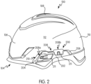
FIG. 2 is a side perspective view of the protective helmet ofFIG. 1A shown without the plurality of accessories; -
FIG. 3A is a detailed front perspective view of an accessory attachment rail of the protective helmet shown in FIG. 2A; -
FIG. 3B is a detailed cross-sectional view of a helmet accessory connected to the accessory attachment rail shown inFIG. 3A ; -
FIG. 3C is a detailed rear perspective view of the accessory attachment rail shown inFIG. 3A ; -
FIG. 4A is a detailed front perspective view of the accessory attachment rail shown during attachment to the protective helmet; -
FIG. 4B is a detailed view of an inside portion of the helmet showing the accessory attachment rail attached to the helmet; -
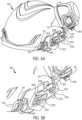
FIG. 5A is an exploded front perspective view of the protective helmet shown inFIG. 1A showing a connection mechanism of an accessory attachment rail; -
FIG. 5B is a detailed view of the connection mechanism of the accessory attachment rail shown inFIG. 5A ; -
FIG. 6 is a perspective view of a protective helmet and an accessory attachment rail in accordance with another non-limiting embodiment or aspect; -
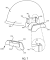
FIG. 7 is a perspective view of a protective helmet and an accessory attachment rail in accordance with another non-limiting embodiment or aspect; -
FIG. 8 is a perspective view of a portion of a protective helmet and an accessory attachment rail in accordance with another non-limiting embodiment or aspect; -
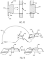
FIG. 9 is a perspective view of a protective helmet and an accessory attachment rail in accordance with another non-limiting embodiment or aspect; -
FIG. 10 is a bottom view of a portion of a protective helmet and an accessory attachment rail in accordance with another non-limiting embodiment or aspect; -
FIG. 11 is a perspective view of a protective helmet and an accessory attachment rail in accordance with another non-limiting embodiment or aspect; -
FIG. 12 is a perspective view of a portion of a protective helmet and an accessory attachment rail in accordance with another non-limiting embodiment or aspect; -
FIG. 13 is a perspective view of a portion of a protective helmet and an accessory attachment rail in accordance with another non-limiting embodiment or aspect; -
FIG. 14 is a perspective view of a portion of a protective helmet and an accessory attachment rail in accordance with another non-limiting embodiment or aspect; -
FIG. 15 is a perspective view of a portion of a protective helmet and an accessory attachment rail in accordance with another non-limiting embodiment or aspect; -
FIG. 16 is a perspective view of a portion of a protective helmet and an accessory attachment rail in accordance with another non-limiting embodiment or aspect; - In
FIGS. 1-16 , like characters refer to the same components and elements, as the case may be, unless otherwise stated. - As used herein, the singular form of "a", "an", and "the" include plural referents unless the context clearly dictates otherwise.
- Spatial or directional terms, such as "left", "right", "inner", "outer", "above", "below", and the like, relate to the invention as shown in the drawing figures and are not to be considered as limiting as the invention can assume various alternative orientations.
- All numbers and ranges used in the specification and claims are to be understood as being modified in all instances by the term "about". By "about" is meant plus or minus twenty-five percent of the stated value, such as plus or minus ten percent of the stated value. However, this should not be considered as limiting to any analysis of the values under the doctrine of equivalents.
- Unless otherwise indicated, all ranges or ratios disclosed herein are to be understood to encompass the beginning and ending values and any and all subranges or subratios subsumed therein. For example, a stated range or ratio of "1 to 10" should be considered to include any and all subranges or subratios between (and inclusive of) the minimum value of 1 and the maximum value of 10; that is, all subranges or subratios beginning with a minimum value of 1 or more and ending with a maximum value of 10 or less. The ranges and/or ratios disclosed herein represent the average values over the specified range and/or ratio.
- The terms "first", "second", and the like are not intended to refer to any particular order or chronology, but refer to different conditions, properties, or elements.
- The term "at least" is synonymous with "greater than or equal to".
- The term "not greater than" is synonymous with "less than or equal to".
- As used herein, "at least one of" is synonymous with "one or more of". For example, the phrase "at least one of A, B, and C" means any one of A, B, or C, or any combination of any two or more of A, B, or C. For example, "at least one of A, B, and C" includes A alone; or B alone; or C alone; or A and B; or A and C; or B and C; or all of A, B, and C.
- The term "adjacent" means proximate to but not in direct contact with.
- The term "includes" is synonymous with "comprises".
- As used herein, the terms "parallel" or "substantially parallel" mean a relative angle as between two objects (if extended to theoretical intersection), such as elongated objects and including reference lines, that is from 0° to 5°, or from 0° to 3°, or from 0° to 2°, or from 0° to 1°, or from 0° to 0.5°, or from 0° to 0.25°, or from 0° to 0.1°, inclusive of the recited values.
- As used herein, the terms "perpendicular" or "substantially perpendicular" mean a relative angle as between two objects at their real or theoretical intersection is from 85° to 90°, or from 87° to 90°, or from 88° to 90°, or from 89° to 90°, or from 89.5° to 90°, or from 89.75° to 90°, or from 89.9° to 90°, inclusive of the recited values.
- With reference to
FIGS. 1A-1B , provided is a protective helmet 100 (hereinafter referred to as "helmet 100") having a rigidouter shell 102 configured to surround the head of a user. In some non-limiting embodiments or aspects, the rigidouter shell 102 may be constructed from a composite material. Theshell 102 has a generally hemi-spherical form and has afacial opening 104 at a front end for accommodating the user's face. Theshell 102 includes afront portion 106 situated above thefacial opening 104, anupper portion 108, and arear portion 110 extending from theupper portion 108 to the nape of the user's neck. A pair oflateral portions 112 extend from theupper portion 108 on each side of thefacial opening 104. - With continued reference to
FIGS. 1A-1B , thehelmet 100 has anaccessory attachment rail 200 attached to eachlateral portion 112, such as at a connection area 114 of eachlateral portion 112. Theaccessory attachment rail 200 is configured for removably receiving at least onehelmet accessory 115, such as aface shield 116 or half-face goggles,earmuffs 118, a headlamp, or any other accessory. The at least onehelmet accessory 115 is configured to increase the functionality of thehelmet 100, such as by providing additional protection to the user or providing additional capability to thehelmet 100. - As described herein, the
face shield 116 and theearmuffs 118 are removably attachable to thehelmet 100 by way of theaccessory attachment rail 200. WhileFIGS. 1A- 1B illustrate a pair ofhelmet accessories 115 attached to thehelmet 100 by way of theaccessory attachment rail 200, other embodiments or aspects of theaccessory attachment rail 200 may be configured for attaching more than twohelmet accessories 115 to thehelmet 100. - With continued reference to
FIGS. 1A-1B , at least onehelmet accessory 115 may be movable between a first or active position, and a second or inactive position. As shown inFIG. 1A , theface shield 116 is configured to extend over thefacial opening 104 of thehelmet 100 in order to protect the user's face. Theface shield 116 is desirably constructed from a transparent material such that the user's vision is not impaired by the presence of theface shield 116 in front of the user's face. Theface shield 116 is movable from the first or active position (FIG. 1A ) to a second or inactive position (FIG. 1B ), such as by a pivoting movement about a first pivot point 119. In some non-limiting embodiments or aspects, theface shield 116 is movable by grasping at least a portion of theface shield 116 and pivoting theface shield 116 relative to thehelmet 100 such that theface shield 116 is moved away from covering thefacial opening 104. In the second or inactive position, theface shield 116 may extend over at least a part of thefront portion 106 and theupper portion 108 of thehelmet 100. Theface shield 116 has a pivoting connection with theaccessory attachment rail 200 to allow movement of theface shield 116 from the first or active position to the second or inactive position via a pivoting or rotating movement about the first pivot point 119. - With continued reference to
FIGS. 1A-1B , each of theearmuffs 118 is configured to extend over the user's ears from thelateral portions 112 of thehelmet 100 in order to protect the user's ears from ambient noise. Theearmuffs 118 desirably have noise suppressing or cancelling properties to reduce or eliminate ambient noise from harming the user's hearing. Each of theearmuffs 118 is movable from the first or active position (FIG. 1A ) to a second or inactive position (FIG. 1B ), such as a pivoting movement about a second pivot point 124. In some non-limiting embodiments or aspects, each of theearmuffs 118 is movable by grasping at least a portion of theearmuff 118 and pivoting theearmuffs 118 relative to thehelmet 100 such that theearmuffs 118 are moved away from covering the user's ears. In the second or inactive position, theearmuffs 118 may extend over at least a part of thelateral portions 112 and therear portion 110 of thehelmet 100. Theearmuffs 118 have aframe 126 having a pivoting connection with theaccessory attachment rail 200 to allow movement of theearmuffs 118 from the first or active position to the second or inactive position via a pivoting or rotating movement about the second pivot point 124. - With reference to
FIG. 2 , thehelmet 100 is illustrated without thehelmet accessories 115 shown inFIGS. 1A-1B . Theaccessory attachment rail 200 remains attached to thehelmet 100 after removal of thehelmet accessories 115 to allow a subsequent reattachment of thehelmet accessories 115. In some embodiments or aspects not covered by the claimed subject matter, theaccessory attachment rail 200 may be non-removably attached to thehelmet 100, such as by way of one or more attachment mechanisms discussed herein. In other embodiments or aspects not covered by the claimed subject matter, theaccessory attachment rail 200 may be monolithically formed with thehelmet 100, such as by molding or co-molding with thehelmet 100. In further non-limiting embodiments or aspects covered by the claimed subject matter, theaccessory attachment rail 200 may be removably attachable to thehelmet 100, such as by way of one or more connection elements discussed herein. - With continued reference to
FIG. 2 , theaccessory attachment rail 200 has abody 202 having afront end 204, arear end 206, and two ormore slots 208 between thefront end 204 and therear end 206. Each of the two ormore slots 208 has anopen end 210 configured for removably receiving onehelmet accessory 115, such as theface shield 116 or theearmuffs 118, and aclosed end 211 opposite theopen end 210. Theclosed end 211 defines a stop surface for preventing further insertion of thehelmet accessory 115 into theslot 208. As shown inFIG. 2 , theaccessory attachment rail 200 has a pair ofslots 208 configured for receiving a pair ofhelmet accessories 115. In this manner, afirst helmet accessory 115, such as the face shield 116 (shown inFIGS. 1A-1B ), can be attached to thefirst slot 208a independently of asecond helmet accessory 115, such as the earmuffs 118 (shown inFIGS. 1A-1B ), which may be attached to thesecond slot 208b of theaccessory attachment rail 200. - The
open end 210 of at least oneslot 208 may be arranged such that it faces thefront portion 106 or theupper portion 108 of thehelmet 100. In this manner, theslot 208 allows for attachment of thehelmet accessory 115 by movement in a direction from thefront portion 106 of the helmet to therear portion 110 of the helmet 100 (front opening slot 208), or by movement in a direction from theupper portion 108 toward a bottom end of the helmet 100 (upward opening slot 208). In other non-limiting embodiments or aspects, theopen end 210 of at least oneslot 208 may be arranged such that it faces therear portion 110 of thehelmet 100 or the bottom end of thehelmet 100 to allow for attachment of thehelmet accessory 115 by movement in a direction from therear portion 110 of the helmet to thefront portion 106 of the helmet 100 (rear opening slot 208) or by movement in a direction toward theupper portion 108 of the helmet 100 (bottom opening slot 208). - With reference to
FIG. 3A , eachslot 208 has a receivingarea 212 configured for receiving a corresponding connector on the helmet accessory 115 (shown inFIGS. 1A-1B ). The receivingarea 212 is defined by achannel 214 having aperimeter sidewall 216. In some non-limiting embodiments or aspects, a width of thechannel 214 may narrow in a direction from theopen end 210 toward theclosed end 211 of theslot 208. In other non-limiting embodiments or aspects, the width of thechannel 214 may be substantially uniform throughout its length in a direction from theopen end 210 toward theclosed end 211 of theslot 208. In some non-limiting embodiments or aspects, thechannel 214 may have aclosed wall 218 on a side immediately adjacent to thehelmet 100 and anopen side 220 on a side opposite theclosed wall 218. Theclosed wall 218 is offset from theopen side 220 by a width of theperimeter sidewall 216. In some non-limiting embodiments or aspects, thechannel 214 may be substantially U-shaped. - With continued reference to
FIGS. 3A-3B , eachslot 208 has a locking mechanism for automatically locking thehelmet accessory 115 within theslot 208 upon insertion of thehelmet accessory 115 within theslot 208 and for preventing removal of thehelmet accessory 115 from theslot 208 until the locking mechanism is unlocked. In some non-limiting embodiments or aspects, the locking mechanism may be alocking beam 222 having alocking tab 224 configured for engaging acorresponding locking slot 138 on the helmet accessory 115 (shown inFIG. 3B ). Thelocking beam 222 may have a cantilevered arrangement with afirst end 226 connected to theclosed wall 218 of theslot 208 and a freesecond end 228 opposite thefirst end 226. Thesecond end 228 of thelocking beam 222 is deflectable relative to thefirst end 226 in a direction toward theclosed wall 218 when urged by at least a portion of thehelmet accessory 115 during insertion of thehelmet accessory 115 into theslot 208. In this manner, thelocking beam 222 is deflectable from a first or initial position toward a second or deflected position to provide a clearance space for thehelmet accessory 115 to be inserted into theslot 208. Arecess 230 may be provided in theclosed wall 218 of theslot 208 to allow deflection of thelocking beam 222 toward the second or deflected position. After insertion of thehelmet accessory 115 into theslot 208, thelocking beam 222 deflects back from the second or deflected position toward the first or initial position such that thelocking beam 222 is captured within thelocking slot 138 on thehelmet accessory 115. In some non-limiting embodiments or aspects, thelocking beam 222 may be deflected from the second or deflected position toward an intermediate position when fully engaged with thehelmet accessory 115. In some non-limiting embodiments or aspects, thelocking beam 222 may be formed on thehelmet accessory 115. - With continued reference to
FIGS. 3A-3B , thelocking tab 224 of thelocking beam 222 has a tapered leadingsurface 232 that is angled toward theopen end 210 of theslot 208. The tapered leadingsurface 232 is the initial contact surface of thelocking beam 222 that is engaged by thehelmet accessory 115 as thehelmet accessory 115 is inserted into theslot 208. The tapered leadingsurface 232 is configured to facilitate deflection of thesecond end 228 of thelocking beam 222 during insertion of thehelmet accessory 115. Arelease button 140 on thehelmet accessory 115 is configured for contacting thelocking tab 224 and deflecting thelocking tab 224 with the pressing of therelease button 140 in a direction toward thehelmet 100. Such movement of therelease button 140 deflects thesecond end 228 of thelocking beam 222 such that thelocking tab 224 disengages from thelocking slot 138 to allow thehelmet accessory 115 to be removed from theslot 208 by pulling thehelmet accessory 115 through theopen end 210 of theslot 208. - With reference to
FIG. 3C , theaccessory attachment rail 200 has one ormore connection elements 234 configured for connecting theaccessory attachment rail 200 to thehelmet 100. In some non-limiting embodiments or aspects, the one ormore connection elements 234 may be configured for non-removably connecting theaccessory attachment rail 200 to thehelmet 100, such as during manufacture of thehelmet 100. In other non-limiting embodiments or aspects, the one ormore connection elements 234 may be configured for removably connecting theaccessory attachment rail 200 to thehelmet 100 to allow free installation and removal of theaccessory attachment rail 200 to and from thehelmet 100. - With continued reference to
FIG. 3C , in some non-limiting embodiments or aspects, the one ormore connection elements 234 may be a plurality of deflectable tabs spaced around aninner surface 236 of theaccessory attachment rail 200 facing the outer surface of thehelmet 100. Eachconnection element 234 may have afirst end 238 connected to thebody 202 of theaccessory attachment rail 200 and asecond end 239 protruding relative to thefirst end 238 in a direction away from theinner surface 236 and toward the outer surface of the helmet. Eachconnection element 234 may have a lockinglip 240 at thesecond end 239 configured for engaging a corresponding ledge on thehelmet 100. For example, as shown inFIG. 4B , thehelmet 100 may have one ormore openings 132 extending through theouter shell 102 in the area of thelateral portion 112 where theaccessory attachment rail 200 is to be attached. The one ormore openings 132 are configured to receive the one ormore connection elements 234 of theaccessory attachment rail 200. Thesecond end 238 of eachconnection element 234 is deflectable relative to thefirst end 236 during contact with an outer surface of thehelmet 100 when during installation of theaccessory attachment rail 200 on thehelmet 100. In this manner, theconnection element 234 is deflectable from a first or initial position toward a second or deflected position to provide a clearance space for theconnection element 234 to be inserted into theopening 132 on thehelmet 100. After insertion of theconnection element 234 into theopening 132, thesecond end 238 of theconnection element 234 deflects back from the second or deflected position toward the first or initial position to lock theconnection element 234 with the lip 136 of theopening 132. - With reference to
FIG. 4A , theaccessory attachment rail 200 may be connected to thehelmet 100 by inserting a first portion of the one ormore connection elements 234 on an upper portion of theaccessory attachment rail 200 into the correspondingopenings 132 on thehelmet 100 and rotating a lower portion of theaccessory attachment rail 200 in a direction toward thehelmet 100 to connect a second portion of the one ormore connection elements 234 on the lower portion of theaccessory attachment rail 200 with the correspondingopenings 132 on thehelmet 100. As described herein, the one ormore connection elements 234 may be configured for non-removably connecting theaccessory attachment rail 200 to thehelmet 100 to prevent removal of theaccessory attachment rail 200 from thehelmet 100. In other non-limiting embodiments or aspects, the one ormore connection elements 234 may be configured for removably connecting theaccessory attachment rail 200 to thehelmet 100 to allow free installation and removal of theaccessory attachment rail 200 to and from thehelmet 100. - With reference to
FIGS. 5A-5B , frames 120, 126 ofvarious helmet accessories 115 are shown prior to connection with theslot 208 of theaccessory attachment rail 200. As shown inFIG. 5B , eachframe slot 208. An inner side of eachframe helmet 100 has a lip (not shown) configured for engaging thelocking tab 224 of thelocking beam 222 when theframe corresponding slot 208. Arelease button 140 on eachframe locking tab 224 and deflecting thelocking tab 224 with the pressing of therelease button 140 in a direction toward thehelmet 100. Such movement of therelease button 140 deflects thesecond end 228 of thelocking beam 222 such that thelocking tab 224 disengages from the lip on theframe frame slot 208 by pulling theframe open end 210 of theslot 208. - With reference to
FIG. 6 , one ormore connection elements 234a is shown in accordance with another embodiment or aspect. Instead of being a deflectable cantilever beam arrangement, such as shown inFIGS. 4A-4B , theconnection elements 234a are configured as annular snaps having apost 242 defined by a pair ofbeams 244 separated from one another by aspace 246. Afirst end 248 of eachbeam 244 is connected to theinner surface 236 of theaccessory attachment rail 200 while asecond end 250 of thebeam 244 protrudes from thefirst end 248 in a direction toward thehelmet 100. Thesecond end 250 has abulbous head 252. The second ends 250 of each of thebeams 244 are configured to deflect toward each other when thebulbous head 252 is inserted through thecorresponding opening 132 on thehelmet 100. After thebulbous head 252 clears theopening 132, the second ends 250 of each of thebeams 244 are configured to deflect away from each other to prevent removal of theaccessory attachment rail 200 from thehelmet 100. The one ormore connection elements 234 may be configured for removably or non-removably connecting theaccessory attachment rail 200 to thehelmet 100, as described herein. - With reference to
FIG. 7 , one ormore connection elements 234b is shown in accordance with another embodiment or aspect. The one ormore connection elements 234b may be formed as aprojection 254 that protrudes from theinner surface 236 of theaccessory attachment rail 200. Theprojection 254 may be configured for being received within a receivingslot 142 on thehelmet 100. In some non-limiting embodiments or aspects, the receivingslot 142 may be defined as a space between a pair of spaced apartarms 144 having afirst end 146 connected to anouter surface 148 of thehelmet 100 and asecond end 150 protruding relative to thefirst end 146 in a direction away from theouter surface 148 of thehelmet 100. Thearms 144 are spaced apart from each other such that theprojection 254 of theaccessory attachment rail 200 can be inserted therebetween to connect theaccessory attachment rail 200 to thehelmet 100. In some non-limiting embodiments or aspects, arecess 152 is recessed into theouter surface 148 of thehelmet 100 and is configured to receive a key 256 on theprojection 254 to prevent removal of theaccessory attachment rail 200 from the receivingslot 142. In some non-limiting embodiments or aspects, theprojection 254 and the receivingslot 142 may be reversed such that theprojection 254 is formed on thehelmet 100, while the receivingslot 142 is formed on theaccessory attachment rail 200. - With reference to
FIG. 8 , one ormore connection elements 234c is shown in accordance with another embodiment or aspect. The one ormore connection elements 234c may be formed as a pair oftabs 258, with onetab 258 protruding away from thefront end 204 of theaccessory attachment rail 200 and theother tab 258 protruding away from therear end 206. Thetabs 258 may be co-planar with thebody 206 of theaccessory attachment rail 200. In some non-limiting embodiments or aspects, thebody 202 and thetabs 258 may be made from a flexible material that allows bending of the accessory attachment rail about its longitudinal plane when a compressive force is applied in the direction of arrows A inFIG. 8 . By compressing thetabs 258 toward each other, thebody 202 of theaccessory attachment rail 200 can be bent to allow insertion of thetabs 258 into the correspondingopenings 132 on thehelmet 100. After releasing the compressive force on thetabs 258, theaccessory attachment rail 200 can revert to its initial shape, which prevents removal of thetabs 258 from theopenings 132 on thehelmet 100. - With reference to
FIG. 9 , one ormore connection elements 234d is shown in accordance with another embodiment or aspect. The one ormore connection elements 234d may be formed as one or more through holes 260 that extend through thebody 202 of theaccessory attachment rail 200. The spacing of the one or more through holes 260 may correspond to the spacing of one ormore openings 132 on thehelmet 100. In this manner, by aligning the through holes 260 on theaccessory attachment rail 200 with theopenings 132 on thehelmet 100, theaccessory attachment rail 200 can be connected to thehelmet 100 by inserting afastener 262 through each through hole 260/opening 132 pair. In some non-limiting embodiments or aspects, thefastener 262 may be a screw, push pin, rivet, or a similar mechanical connection element. Thefastener 262 may be configured for non-removably connecting theaccessory attachment rail 200 to thehelmet 100 to prevent removal of theaccessory attachment rail 200 from thehelmet 100. In other non-limiting embodiments or aspects, thefastener 262 may be configured for removably connecting theaccessory attachment rail 200 to thehelmet 100 to allow free installation and removal of theaccessory attachment rail 200 to and from thehelmet 100. - With reference to
FIG. 10 , one ormore connection elements 234e is shown in accordance with another embodiment or aspect. The one ormore connection elements 234e may be formed as atapered flange 264 that protrudes from theinner surface 236 of theaccessory attachment rail 200 in a direction toward the outer surface of thehelmet 100. A width of the taperedflange 264 may increase in a direction from theinner surface 236 of theaccessory attachment rail 200 toward the outer surface of thehelmet 100. The taperedflange 264 is configured for being received within acutout 154 on thehelmet 100. In some non-limiting embodiments or aspects, the taperedflange 264 may be configured for a press fit or an interference fit with thecutout 154 to prevent removal of theaccessory attachment rail 200 from thehelmet 100 after the taperedflange 264 is inserted into thecutout 154. - With reference to
FIG. 11 , one ormore connection elements 234f is shown in accordance with another embodiment or aspect. The one ormore connection elements 234f may be formed as aknob 266 that protrudes from theinner surface 236 of theaccessory attachment rail 200 in a direction toward the outer surface of thehelmet 100. Theknob 266 is configured for being received within aslot 156 on thehelmet 100. Theslot 156 may be shaped such that theknob 266 may be inserted at a first end of theslot 156. Theknob 266 may be movable within theslot 156 toward a second end to allow for locking of theknob 266 within theslot 156. In some non-limiting embodiments or aspects, one ormore ramps 158 may be provided on a guidingsurface 160 of theslot 156 to prevent removal of theaccessory attachment rail 200 from thehelmet 100 after theknob 266 is inserted into theslot 156 and over the one ormore ramps 158. Theknob 266 and theslot 156 define a keyed connection arrangement with a "slide-to-lock" feature. - With reference to
FIG. 12 , arelease button 140a for use with theframe helmet accessory 115 is shown in accordance with another embodiment or aspect. Instead of being formed as a distinct component that is separate from theframe 120, 126 (shown inFIGS. 5A-5B ), therelease button 140a is formed directly on theframe frame release button 140a may be configured as a cantilever having afirst end 162 connected to theframe free end 164 deflectable relative to thefirst end 162. Thesecond end 164 has acatch 166 that interacts with thelocking tab 224 on theaccessory attachment rail 200. Thecatch 166 is configured for contacting thelocking tab 224 and deflecting thelocking tab 224 with the pressing of therelease button 140a in a direction toward thehelmet 100. Such movement of therelease button 140 deflects thesecond end 228 of thelocking beam 222 such that thelocking tab 224 disengages from the lip on theframe frame slot 208. - With reference to
FIG. 13 , arelease button 140b on theframe helmet accessory 115 is shown in accordance with another embodiment or aspect. In some non-limiting embodiments or aspects, therelease button 140b may be configured as a slider button that is configured for a sliding movement relative to theframe frame release button 140b is movable relative to theframe release button 140b to the initial position. In this manner, after moving therelease button 140b to the release position, the biasing mechanism may urge therelease button 140b back toward the initial position in a direction of arrow C. Therelease button 140b may have arelease tab 168 that is slidable relative to theframe release button 140b toward the release position, therelease tab 168 contacts the tapered leadingsurface 232 of thelocking beam 222 on theaccessory attachment rail 200, thereby causing thelocking beam 222 to deflect and allowing theframe slot 208. - With reference to
FIG. 14 , anaccessory attachment rail 200a is shown in accordance with another embodiment or aspect. Theaccessory attachment rail 200a has a locking mechanism for attaching a correspondinghelmet accessory 115. In some non-limiting embodiments or aspects, the locking mechanism may be formed as areceptacle 268 having anopening 270 configured for receiving aflexible snap 170 formed on thehelmet accessory 115. Theflexible snap 170 is configured to deflect from its initial state during insertion of thesnap 170 into a first end of theopening 270 of thereceptacle 268. Once thesnap 170 exits through a second end of theopening 270, theflexible snap 170 may "snap" back to its initial state, thereby preventing removal of thehelmet accessory 115 from theaccessory attachment rail 200a without flexing or deflecting thesnap 170 to a release state. - With reference to
FIG. 15 , anaccessory attachment rail 200b is shown in accordance with another embodiment or aspect. Theaccessory attachment rail 200b has a locking mechanism for attaching a correspondinghelmet accessory 115. In some non-limiting embodiments or aspects, the locking mechanism may be formed as anaperture 272 configured for receivingflexible legs 172 formed on thehelmet accessory 115. Theflexible legs 172 are configured to deflect from their initial state during insertion of thelegs 172 into a first end of theaperture 272. Once thelegs 172 exit through a second end of theaperture 272, theflexible legs 172 may "snap" back to their initial state, thereby preventing removal of thehelmet accessory 115 from theaccessory attachment rail 200b without flexing or deflecting theflexible legs 172 to a release state. In some embodiments or aspects, arelease member 174 is provided to urge theflexible legs 172 toward a flexed or release state. Therelease member 174 is configured to translate along a longitudinal length of theflexible legs 172, thereby urging thelegs 172 toward each other with continued movement of therelease member 174. - With reference to
FIG. 16 , anaccessory attachment rail 200c is shown in accordance with another embodiment or aspect. Theaccessory attachment rail 200c has a locking mechanism for attaching a correspondinghelmet accessory 115. In some non-limiting embodiments or aspects, the locking mechanism may be formed as akeyed slot 274 configured for receiving a spring-loadedlocking tab 176 formed on thehelmet accessory 115. Thekeyed slot 274 has afirst portion 276 and asecond portion 278, wherein a width of thefirst portion 276 is smaller than a width of thesecond portion 278. Thelocking tab 176 has a lockinghead 178 having a width that is smaller than a width of thesecond portion 278 of thekeyed slot 274 but larger than the width of thefirst portion 276 of thekeyed slot 274. In this manner, the lockinghead 178 can be inserted into and removed from thesecond portion 278, but not thefirst portion 276 of thekeyed slot 274. Upon insertion of the lockinghead 178 into thesecond portion 278 of thekeyed slot 274, the spring-loadedlocking tab 176 may urge the locking head to slide along the channel of thefirst portion 276 of thekeyed slot 274. Due to the width of the lockinghead 178, thelocking tab 176 cannot be removed from the keyedslot 274. By sliding or urging thelocking tab 176 toward thesecond portion 278, thelocking tab 176 can be removed from the keyedslot 274 when the lockinghead 178 is positioned within thesecond portion 278. A biasing mechanism, such as a spring 180, may be provided for biasing thelocking tab 176 toward thefirst portion 276 of thekeyed slot 274. In this manner, after insertion of the lockinghead 178 into thesecond portion 278 of thekeyed slot 274, the spring 180 may urge thelocking tab 176 toward thefirst portion 276 of thekeyed slot 274, thereby preventing removal of the helmet accessory from theaccessory attachment rail 200c.
Claims (15)
- A protective helmet (100) comprising:an outer shell (102) configured for surrounding a head of a user;at least one accessory attachment rail (200) connected to the outer shell (102), the accessory attachment rail (200) comprising:a body (202) having a front end (204), a rear end (206), and two or more slots (208, 208a, 208b) between the front end (204) and the rear end (206), each of the two or more slots (208, 208a, 208b) configured for removably receiving at least one helmet accessory (115);a locking mechanism (222) associated with each of the two or more slots (208, 208a, 208b) for automatically locking the at least one helmet accessory (115) in at least one of the two or more slots (208, 208a, 208b) upon insertion of the at least one helmet accessory (115) within at least one of the two or more slots (208, 208a, 208b) and for preventing removal of the at least one helmet accessory (115) from within the at least one of the two or more slots (208, 208a, 208b) until the locking mechanism (222) is unlocked; andat least one connection element (234) for connecting the accessory attachment rail (200) to the outer shell (102);wherein each of the two or more slots (208, 208a, 208b) has an open end (210) configured for removably receiving the at least one helmet accessory (115), a closed end (211) opposite the open end (210), and a channel (214) having a perimeter wall (216) between the open end (210) and the closed end (211).
- The protective helmet of claim 1, whereini) a first helmet accessory (115, 116) can be attached to the first slot (208a) independent from a second helmet accessory (115, 118), which may be attached to the second slot (208b) of the accessory attachment rail (200);ii) a) a front opening slot (208a) having an open end (210) being arranged such that it faces a front portion of the helmet (100) to allow for attachment of a helmet accessory (115) by movement in a direction from a front portion (106) of the helmet (100) to a rear portion (110) of the helmet (100),b) an upward opening slot (208b) having an open end (210) being arranged such that it faces an upper portion of the helmet (100) to allow for attachment of the helmet accessory (115) by movement in a direction from an upper portion (108) toward a bottom end of the helmet (100),c) an rear opening slot (208) having an open end (210) being arranged such that it faces a rear portion (110) of the helmet (100) to allow for attachment of the helmet accessory (115) by movement in a direction from the rear portion (110) of the helmet (100) to the front portion (106) of the helmet (100), ord) a bottom opening slot (208) having an open end (210) being arranged such that it faces the bottom end of the helmet (100) to allow for attachment of the helmet accessory (115) by movement in a direction toward the upper portion (108) of the helmet (100); and/oriii) the locking mechanism comprises a locking beam (222) having a first end (226) connected to at least a portion of the two or more slots (208, 208a, 208b) and a second free end (228) movable relative to the first end (226) in a direction toward an outer surface of the helmet (100) when deflected by the at least one helmet accessory (115) during insertion of the at least one helmet accessory (115) into the at least one of the two or more slots (208, 208a, 208b).
- The protective helmet of claim 2, wherein the second free end (228) of the locking beam (222) has a locking tab (224) configured for engaging a corresponding locking slot (138) on the at least one helmet accessory (115) when the at least one helmet accessory (115) is fully inserted into the at least one of the two or more slots (208, 208a, 208b).
- The protective helmet of claim 3, wherein the locking tab (224) has a tapered leading surface (232) that is angled toward the open end (210) of the two or more slots (208, 208a, 208b).
- The protective helmet of claim 1, wherein the at least one connection element is a plurality of deflectable tabs spaced around an inner surface of the accessory attachment rail (200) facing an outer surface of the outer shell (102), each of the plurality of deflectable tabs configured for insertion into an opening (132) formed on the outer shell (102).
- The protective helmet of claim 5, wherein each of the plurality of deflectable tabs has a first end (238) connected to the body (202) of the accessory attachment rail (200) and a second end (239) protruding relative to the first end (238) in a direction away from the inner surface and toward the outer surface (148) of the outer shell (102).
- The protective helmet of claim 5, wherein each deflectable tab has a lip (240) for engaging a corresponding ledge on the outer shell (102).
- The protective helmet of claim 1, wherein the at least one connection element (234a) is a plurality of annular snaps having a post (242) defined by a pair of deflectable beams (244) separated from each other by a space (246), each of the plurality of annular snaps configured for insertion into an opening (132) formed on the outer shell (102).
- The protective helmet of claim 8, wherein each of the deflectable beams (244) has a first end (248) connected to the body (202) of the accessory attachment rail (200) and a second free end (250) protruding from the body (202) in a direction toward an outer surface (148) of the outer shell (102).
- The protective helmet of claim 1, wherein the at least one connection element is a projection (254) that protrudes from an inner surface (236) of the body (202) in a direction toward an outer surface of the outer shell (102), the projection (254) being configured for insertion into a receiving slot (142) protruding away from the outer surface (148) of the outer shell (102).
- The protective helmet of claim 1, wherein the at least one connection element is a pair of tabs (258) protruding from the first end (204) and the second end (206) of the body (202).
- The protective helmet of claim 1, wherein the at least one connection element is at least one through hole (260) extending through the body (202) and configured to receive a fastener (262) therethrough to connect the accessory attachment rail (200) to the outer shell (102).
- The protective helmet of claim 1, further comprising the at least one helmet accessory (115).
- The protective helmet of claim 13, wherein the at least one helmet accessory is at least one of a face shield (116), earmuffs (118), and a headlamp.
- The protective helmet of claim 13, wherein the at least one helmet accessory comprises a frame (120, 126) movable between a first or active position and a second or inactive position by pivoting relative to the accessory attachment rail (200) about a pivot point (124).
Applications Claiming Priority (2)
| Application Number | Priority Date | Filing Date | Title |
|---|---|---|---|
| US16/207,842 US10912344B2 (en) | 2018-12-03 | 2018-12-03 | Helmet with accessory attachment rail |
| PCT/US2019/063980 WO2020117661A1 (en) | 2018-12-03 | 2019-12-02 | Helmet with accessory attachment rail |
Publications (3)
| Publication Number | Publication Date |
|---|---|
| EP3890540A1 EP3890540A1 (en) | 2021-10-13 |
| EP3890540A4 EP3890540A4 (en) | 2022-08-03 |
| EP3890540B1 true EP3890540B1 (en) | 2025-02-12 |
Family
ID=70850904
Family Applications (1)
| Application Number | Title | Priority Date | Filing Date |
|---|---|---|---|
| EP19891778.3A Active EP3890540B1 (en) | 2018-12-03 | 2019-12-02 | Helmet with accessory attachment rail |
Country Status (4)
| Country | Link |
|---|---|
| US (1) | US10912344B2 (en) |
| EP (1) | EP3890540B1 (en) |
| CN (1) | CN113163888B (en) |
| WO (1) | WO2020117661A1 (en) |
Families Citing this family (26)
| Publication number | Priority date | Publication date | Assignee | Title |
|---|---|---|---|---|
| ES2880033T3 (en) | 2017-11-07 | 2021-11-23 | Locatelli S P A | Crash helmet |
| US11452327B2 (en) * | 2018-01-26 | 2022-09-27 | Klein Tools, Inc. | Safety helmet |
| FR3083441B1 (en) * | 2018-07-06 | 2020-06-19 | Msa Europe Gmbh | HEARING PROTECTION DEVICE |
| AU2020274433A1 (en) * | 2019-05-16 | 2021-12-02 | Locatelli S.P.A. | Protective helmet |
| USD955649S1 (en) * | 2019-10-31 | 2022-06-21 | Uvex Arbeitsschutz Gmbh | Head guard |
| USD927787S1 (en) * | 2020-01-17 | 2021-08-10 | E.D. Bullard Company | Protective helmet |
| USD927788S1 (en) * | 2020-01-17 | 2021-08-10 | E.D. Bullard Company | Protective helmet |
| CA3114907A1 (en) * | 2020-04-13 | 2021-10-13 | Method Innovation Partners Inc. | Systems and methods for attaching accessories to headgear |
| CN116018078B (en) | 2020-08-17 | 2025-12-09 | 米沃奇电动工具公司 | Safety headgear and accessory |
| CA3188089A1 (en) | 2020-08-17 | 2022-02-24 | Todd Andrew Zeilinger | Hard hat attachment system and sun visor |
| USD1004850S1 (en) * | 2021-03-17 | 2023-11-14 | Studson, Inc. | Protective helmet |
| USD995924S1 (en) * | 2021-03-17 | 2023-08-15 | Studson, Inc. | Protective helmet |
| USD1115179S1 (en) | 2020-09-23 | 2026-02-24 | Studson, Inc. | Protective helmet |
| USD995925S1 (en) * | 2020-09-23 | 2023-08-15 | Studson, Inc. | Protective helmet |
| US11896074B2 (en) * | 2020-10-30 | 2024-02-13 | Rpb Safety, Llc | Head top |
| WO2022096918A1 (en) * | 2020-11-05 | 2022-05-12 | Cardo Systems, Ltd. | Magnetic fastening device |
| GB2601335B (en) * | 2020-11-26 | 2022-11-30 | Racal Acoustics Ltd | An attachment bracket for an earshell |
| EP4287902A4 (en) | 2021-02-08 | 2025-04-09 | Milwaukee Electric Tool Corporation | SAFETY HELMET PROTECTION VISOR MOUNTING SYSTEM |
| CA3210574A1 (en) | 2021-03-12 | 2022-09-15 | Nicole Z. SUMMERSETT | Safety headwear systems and accessories |
| DE112022004305T5 (en) | 2021-11-22 | 2024-07-18 | Milwaukee Electric Tool Corporation | SAFETY HELMET ACCESSORY HOLDER |
| USD971508S1 (en) * | 2022-07-13 | 2022-11-29 | Ruiyin Cao | Safety helmet |
| US20240156200A1 (en) * | 2022-11-11 | 2024-05-16 | U-Power Group S.P.A. | Shell for protective helmet and associated protective helmet |
| US12274323B2 (en) * | 2023-06-20 | 2025-04-15 | Ourad Safety Co., Ltd. | Device for connecting lens and earmuff to safety helmet |
| SI26569A (en) * | 2023-12-04 | 2025-06-30 | Bikerguard D.O.O. | Mounting assembly, helmet visor wiper with said assembly for attachment to a visor, visor and helmet with said wiper |
| US20250228323A1 (en) * | 2024-01-11 | 2025-07-17 | Milwaukee Electric Tool Corporation | Hard Hat Attachment System and Safety Equipment |
| WO2025165723A1 (en) * | 2024-01-29 | 2025-08-07 | Milwaukee Electric Tool Corporation | Hard hat communication system |
Family Cites Families (48)
| Publication number | Priority date | Publication date | Assignee | Title |
|---|---|---|---|---|
| US3461463A (en) * | 1967-06-09 | 1969-08-19 | American Optical Corp | Ear protector suspension devices and the combination with headgear |
| SE409539B (en) * | 1978-03-07 | 1979-08-27 | Hellberg Protection Ab | DEVICE FOR ATTACHING TO A SAFETY LOSTAGLE A FOLDABLE VISOR |
| DE59406401D1 (en) * | 1993-09-30 | 1998-08-13 | Artilux Herzig Ag | Fastening system for a face shield and / or ear muffs on a work helmet |
| FI982681A0 (en) | 1998-12-11 | 1998-12-11 | Arimo Ristola | Mounting arrangement for attaching guards to the helmet |
| ATE338481T1 (en) * | 2002-09-12 | 2006-09-15 | Opticos Srl | DEVICE FOR ATTACHING A VISOR TO A HELMET |
| US6807679B1 (en) | 2003-04-09 | 2004-10-26 | Chen Li Optical Co., Ltd. | Mechanism for securing eye protector to helmet |
| US6892393B1 (en) | 2003-12-29 | 2005-05-17 | Jack Provost | Safety helmet attachment and method for shielding eyes |
| PL1874147T3 (en) * | 2005-04-25 | 2010-10-29 | Msa Production France | Device for removeably fixing an illuminating lamp and a protective helmet with such a device |
| US7908667B2 (en) * | 2005-06-17 | 2011-03-22 | Artisent, Inc. | Mounting system for accessories on a safety helmet |
| US9072328B2 (en) | 2005-06-17 | 2015-07-07 | Artisent, Llc | Hinged attachment of headgear to a helmet |
| US7849517B2 (en) | 2005-06-17 | 2010-12-14 | Artisent, Inc. | Mounting system for accessories on a safety helmet |
| KR100748611B1 (en) | 2006-04-12 | 2007-08-13 | 한국전력공사 | Hard hat for safety |
| DE102006040555A1 (en) * | 2006-08-30 | 2008-03-06 | Andreas Stihl Ag & Co. Kg | Protective headgear combination |
| WO2008025083A1 (en) | 2006-08-31 | 2008-03-06 | David John Springer | Hard hat with attached safety glasses |
| US20100012692A1 (en) * | 2008-05-19 | 2010-01-21 | Bae Systems Aerospace & Defense Group Inc. | Helmet Attachment Platform |
| US8245320B2 (en) | 2008-12-23 | 2012-08-21 | Dennis Jenkins | Safety helmet attachment and method for shielding eyes |
| DE102010026997A1 (en) * | 2010-07-13 | 2012-01-19 | Anton Pfanner | Hearing protection for attachment to a protective helmet, in particular for forestry workers |
| DE102010027012A1 (en) * | 2010-07-13 | 2012-01-19 | Anton Pfanner | Hard hat, especially for forestry workers |
| DE102010027015A1 (en) * | 2010-07-13 | 2012-01-19 | Anton Pfanner | Face shield for attachment to a protective helmet, in particular for forestry workers |
| BR112013018029A2 (en) | 2011-04-01 | 2019-09-24 | Mine Safety Appliances Co | system and adapter for use in connection with a protective helmet and method for connecting accessories to a protective helmet |
| DE102012000370B4 (en) * | 2012-01-11 | 2017-02-02 | Pfanner Schutzbekleidung Gmbh | Hard hat, especially for mountaineers and tree climbers |
| DE102012015023A1 (en) * | 2012-07-27 | 2014-01-30 | Pfanner Schutzbekleidung Gmbh | Visor and its combination with a protective helmet |
| US9516911B2 (en) | 2013-03-29 | 2016-12-13 | Kimberly-Clark Worldwide, Inc. | Hardhat accessory interchange system |
| US10617168B2 (en) * | 2014-01-14 | 2020-04-14 | Gentex Corporation | Pivot-arm assembly for a helmet mounted headset |
| FR3016498B1 (en) * | 2014-01-21 | 2016-05-06 | Msa Gallet | PROTECTIVE HELMET EQUIPPED WITH A MOBILE FACIAL SCREEN |
| US9578916B2 (en) | 2014-02-11 | 2017-02-28 | 3M Innovative Properties Company | Appliance mounting device and system for head gear |
| US10959477B2 (en) * | 2014-05-02 | 2021-03-30 | 3M Innovative Properties Company | Ear muff attachment having dual axis of rotation |
| WO2016057792A1 (en) | 2014-10-09 | 2016-04-14 | Artisent, Llc | Helmet mounted visor |
| US9933112B2 (en) * | 2015-01-16 | 2018-04-03 | Matthew A. Sharron | Mounting device |
| US10154704B1 (en) * | 2015-04-17 | 2018-12-18 | Desmark Industries, Inc. | Helmet slide assembly |
| US9872531B2 (en) | 2015-09-28 | 2018-01-23 | Alan Uke | Helmet assembly |
| EP3359904B8 (en) * | 2015-10-09 | 2021-04-21 | Avon Protection Ceradyne LLC | Accessory mounting device and system using same |
| ITUB20154758A1 (en) | 2015-10-27 | 2017-04-27 | Kask Spa | BAND POGGIA FRONT FOR HELMETS AND HELMET PROVIDED WITH SUCH FRONT POGGIA BAND. |
| ITUB20154957A1 (en) | 2015-10-27 | 2017-04-27 | Kask Spa | HELMET. |
| DE102016100086A1 (en) * | 2016-01-04 | 2017-07-06 | Pfanner Schutzbekleidung Gmbh | Earmuffs, communication system and safety helmet |
| US9716938B1 (en) * | 2016-01-21 | 2017-07-25 | Division Group, LLC | Headset mount |
| DE102016205448B4 (en) * | 2016-04-01 | 2019-02-07 | Uvex Arbeitsschutz Gmbh | helmet |
| US11103021B2 (en) * | 2016-05-25 | 2021-08-31 | Safariland, Llc | Headset with dual battery compartment |
| US10350113B2 (en) * | 2016-05-25 | 2019-07-16 | Safariland, Llc | Headset |
| US10371487B2 (en) * | 2016-10-03 | 2019-08-06 | Revision Military S.A.R.L. | Helmet accessory attachment system |
| EP3340643A1 (en) * | 2016-12-21 | 2018-06-27 | Safariland, LLC | Rail connector for earcup suspension assembly |
| US11350689B2 (en) * | 2017-01-13 | 2022-06-07 | Gentex Corporation | Helmet mounted visor |
| WO2018148705A1 (en) * | 2017-02-13 | 2018-08-16 | Otto Engineering, Inc. | Headset mounts |
| PL3595472T3 (en) * | 2017-03-13 | 2022-11-21 | Gentex Corporation | Mounting rail assembly |
| WO2018190892A1 (en) * | 2017-04-12 | 2018-10-18 | Visor Nation Inc. | Baseball helmet with visor |
| JP6842993B2 (en) * | 2017-05-22 | 2021-03-17 | 株式会社Shoei | Helmet |
| US10928163B2 (en) * | 2017-10-04 | 2021-02-23 | Trent Zimmer | Ballistic helmet |
| IT201800007545A1 (en) * | 2018-07-26 | 2020-01-26 | Nolangroup Spa | Protective helmet with visor lifting / lowering mechanism |
-
2018
- 2018-12-03 US US16/207,842 patent/US10912344B2/en active Active
-
2019
- 2019-12-02 EP EP19891778.3A patent/EP3890540B1/en active Active
- 2019-12-02 CN CN201980079808.4A patent/CN113163888B/en active Active
- 2019-12-02 WO PCT/US2019/063980 patent/WO2020117661A1/en not_active Ceased
Also Published As
| Publication number | Publication date |
|---|---|
| CN113163888B (en) | 2024-04-02 |
| WO2020117661A1 (en) | 2020-06-11 |
| EP3890540A4 (en) | 2022-08-03 |
| US10912344B2 (en) | 2021-02-09 |
| CN113163888A (en) | 2021-07-23 |
| US20200170329A1 (en) | 2020-06-04 |
| EP3890540A1 (en) | 2021-10-13 |
Similar Documents
| Publication | Publication Date | Title |
|---|---|---|
| US10912344B2 (en) | Helmet with accessory attachment rail | |
| EP3998892B1 (en) | Protective helmet with face protection shield and linkage mechanism | |
| US5546610A (en) | Fastening system for fastening a face-protection sheild and/or hearing protection caps to a work helmet | |
| EP3595472B1 (en) | Mounting rail assembly | |
| EP2806760B1 (en) | Protective helmet and face-shield | |
| US9201251B2 (en) | Eyewear assembly with side shields attachable to inner surfaces of temples | |
| US10209457B2 (en) | Protection cap for optical connector plug | |
| US9671568B2 (en) | Optical connector plug with shutter | |
| US20150342283A1 (en) | Attachment mechanism | |
| US20160143785A1 (en) | Protective eye mask, particularly for skiing | |
| CN105188440A (en) | Hardhat accessory interchange system | |
| WO2008041688A1 (en) | Slide adjuster for belt and buckle | |
| US20220369754A1 (en) | Visor mechanism for a safety helmet | |
| CN109907441B (en) | Wrist-worn equipment and wrist-worn equipment watchband | |
| EP2775877B1 (en) | Helmet-mask adapter locking system | |
| CA1080447A (en) | Fastening means for safety belts | |
| US6357053B1 (en) | Safety goggles | |
| KR101701243B1 (en) | Helmet | |
| US20070234526A1 (en) | Clipping piece structure for goggles | |
| KR102006654B1 (en) | Safety Helmet Having Drawer Type Protect Glasses | |
| JP5373727B2 (en) | Work helmet | |
| JP2000303244A (en) | Mounting tool for interior material of helmet | |
| KR200485771Y1 (en) | A buckle for headband | |
| EP2825069A1 (en) | Protective helmet and ocular screen | |
| GB2161611A (en) | Safety spectacles |
Legal Events
| Date | Code | Title | Description |
|---|---|---|---|
| STAA | Information on the status of an ep patent application or granted ep patent |
Free format text: STATUS: THE INTERNATIONAL PUBLICATION HAS BEEN MADE |
|
| PUAI | Public reference made under article 153(3) epc to a published international application that has entered the european phase |
Free format text: ORIGINAL CODE: 0009012 |
|
| STAA | Information on the status of an ep patent application or granted ep patent |
Free format text: STATUS: REQUEST FOR EXAMINATION WAS MADE |
|
| 17P | Request for examination filed |
Effective date: 20210617 |
|
| AK | Designated contracting states |
Kind code of ref document: A1 Designated state(s): AL AT BE BG CH CY CZ DE DK EE ES FI FR GB GR HR HU IE IS IT LI LT LU LV MC MK MT NL NO PL PT RO RS SE SI SK SM TR |
|
| DAV | Request for validation of the european patent (deleted) | ||
| DAX | Request for extension of the european patent (deleted) | ||
| A4 | Supplementary search report drawn up and despatched |
Effective date: 20220706 |
|
| RIC1 | Information provided on ipc code assigned before grant |
Ipc: A42B 3/04 20060101AFI20220630BHEP |
|
| P01 | Opt-out of the competence of the unified patent court (upc) registered |
Effective date: 20230626 |
|
| GRAP | Despatch of communication of intention to grant a patent |
Free format text: ORIGINAL CODE: EPIDOSNIGR1 |
|
| STAA | Information on the status of an ep patent application or granted ep patent |
Free format text: STATUS: GRANT OF PATENT IS INTENDED |
|
| INTG | Intention to grant announced |
Effective date: 20240510 |
|
| RIN1 | Information on inventor provided before grant (corrected) |
Inventor name: HEHMAN, DANIEL MARTIN Inventor name: KLOTZ, ROBERT EDWARD Inventor name: BOHN, ALEXA DANIELLE |
|
| GRAS | Grant fee paid |
Free format text: ORIGINAL CODE: EPIDOSNIGR3 |
|
| GRAJ | Information related to disapproval of communication of intention to grant by the applicant or resumption of examination proceedings by the epo deleted |
Free format text: ORIGINAL CODE: EPIDOSDIGR1 |
|
| GRAL | Information related to payment of fee for publishing/printing deleted |
Free format text: ORIGINAL CODE: EPIDOSDIGR3 |
|
| STAA | Information on the status of an ep patent application or granted ep patent |
Free format text: STATUS: REQUEST FOR EXAMINATION WAS MADE |
|
| GRAP | Despatch of communication of intention to grant a patent |
Free format text: ORIGINAL CODE: EPIDOSNIGR1 |
|
| STAA | Information on the status of an ep patent application or granted ep patent |
Free format text: STATUS: GRANT OF PATENT IS INTENDED |
|
| INTC | Intention to grant announced (deleted) | ||
| INTG | Intention to grant announced |
Effective date: 20241016 |
|
| GRAA | (expected) grant |
Free format text: ORIGINAL CODE: 0009210 |
|
| STAA | Information on the status of an ep patent application or granted ep patent |
Free format text: STATUS: THE PATENT HAS BEEN GRANTED |
|
| AK | Designated contracting states |
Kind code of ref document: B1 Designated state(s): AL AT BE BG CH CY CZ DE DK EE ES FI FR GB GR HR HU IE IS IT LI LT LU LV MC MK MT NL NO PL PT RO RS SE SI SK SM TR |
|
| REG | Reference to a national code |
Ref country code: GB Ref legal event code: FG4D |
|
| REG | Reference to a national code |
Ref country code: CH Ref legal event code: EP |
|
| REG | Reference to a national code |
Ref country code: DE Ref legal event code: R096 Ref document number: 602019065946 Country of ref document: DE |
|
| REG | Reference to a national code |
Ref country code: IE Ref legal event code: FG4D |
|
| REG | Reference to a national code |
Ref country code: NL Ref legal event code: MP Effective date: 20250212 |
|
| PG25 | Lapsed in a contracting state [announced via postgrant information from national office to epo] |
Ref country code: RS Free format text: LAPSE BECAUSE OF FAILURE TO SUBMIT A TRANSLATION OF THE DESCRIPTION OR TO PAY THE FEE WITHIN THE PRESCRIBED TIME-LIMIT Effective date: 20250512 |
|
| PG25 | Lapsed in a contracting state [announced via postgrant information from national office to epo] |
Ref country code: FI Free format text: LAPSE BECAUSE OF FAILURE TO SUBMIT A TRANSLATION OF THE DESCRIPTION OR TO PAY THE FEE WITHIN THE PRESCRIBED TIME-LIMIT Effective date: 20250212 |
|
| PG25 | Lapsed in a contracting state [announced via postgrant information from national office to epo] |
Ref country code: PL Free format text: LAPSE BECAUSE OF FAILURE TO SUBMIT A TRANSLATION OF THE DESCRIPTION OR TO PAY THE FEE WITHIN THE PRESCRIBED TIME-LIMIT Effective date: 20250212 |
|
| PG25 | Lapsed in a contracting state [announced via postgrant information from national office to epo] |
Ref country code: ES Free format text: LAPSE BECAUSE OF FAILURE TO SUBMIT A TRANSLATION OF THE DESCRIPTION OR TO PAY THE FEE WITHIN THE PRESCRIBED TIME-LIMIT Effective date: 20250212 |
|
| REG | Reference to a national code |
Ref country code: LT Ref legal event code: MG9D |
|
| PG25 | Lapsed in a contracting state [announced via postgrant information from national office to epo] |
Ref country code: IS Free format text: LAPSE BECAUSE OF FAILURE TO SUBMIT A TRANSLATION OF THE DESCRIPTION OR TO PAY THE FEE WITHIN THE PRESCRIBED TIME-LIMIT Effective date: 20250612 Ref country code: NO Free format text: LAPSE BECAUSE OF FAILURE TO SUBMIT A TRANSLATION OF THE DESCRIPTION OR TO PAY THE FEE WITHIN THE PRESCRIBED TIME-LIMIT Effective date: 20250512 |
|
| PG25 | Lapsed in a contracting state [announced via postgrant information from national office to epo] |
Ref country code: NL Free format text: LAPSE BECAUSE OF FAILURE TO SUBMIT A TRANSLATION OF THE DESCRIPTION OR TO PAY THE FEE WITHIN THE PRESCRIBED TIME-LIMIT Effective date: 20250212 |
|
| PG25 | Lapsed in a contracting state [announced via postgrant information from national office to epo] |
Ref country code: HR Free format text: LAPSE BECAUSE OF FAILURE TO SUBMIT A TRANSLATION OF THE DESCRIPTION OR TO PAY THE FEE WITHIN THE PRESCRIBED TIME-LIMIT Effective date: 20250212 |
|
| PG25 | Lapsed in a contracting state [announced via postgrant information from national office to epo] |
Ref country code: LV Free format text: LAPSE BECAUSE OF FAILURE TO SUBMIT A TRANSLATION OF THE DESCRIPTION OR TO PAY THE FEE WITHIN THE PRESCRIBED TIME-LIMIT Effective date: 20250212 Ref country code: PT Free format text: LAPSE BECAUSE OF FAILURE TO SUBMIT A TRANSLATION OF THE DESCRIPTION OR TO PAY THE FEE WITHIN THE PRESCRIBED TIME-LIMIT Effective date: 20250612 |
|
| PG25 | Lapsed in a contracting state [announced via postgrant information from national office to epo] |
Ref country code: BG Free format text: LAPSE BECAUSE OF FAILURE TO SUBMIT A TRANSLATION OF THE DESCRIPTION OR TO PAY THE FEE WITHIN THE PRESCRIBED TIME-LIMIT Effective date: 20250212 Ref country code: GR Free format text: LAPSE BECAUSE OF FAILURE TO SUBMIT A TRANSLATION OF THE DESCRIPTION OR TO PAY THE FEE WITHIN THE PRESCRIBED TIME-LIMIT Effective date: 20250513 |
|
| REG | Reference to a national code |
Ref country code: AT Ref legal event code: MK05 Ref document number: 1765181 Country of ref document: AT Kind code of ref document: T Effective date: 20250212 |
|
| PG25 | Lapsed in a contracting state [announced via postgrant information from national office to epo] |
Ref country code: SE Free format text: LAPSE BECAUSE OF FAILURE TO SUBMIT A TRANSLATION OF THE DESCRIPTION OR TO PAY THE FEE WITHIN THE PRESCRIBED TIME-LIMIT Effective date: 20250212 |
|
| PG25 | Lapsed in a contracting state [announced via postgrant information from national office to epo] |
Ref country code: SM Free format text: LAPSE BECAUSE OF FAILURE TO SUBMIT A TRANSLATION OF THE DESCRIPTION OR TO PAY THE FEE WITHIN THE PRESCRIBED TIME-LIMIT Effective date: 20250212 |
|
| PG25 | Lapsed in a contracting state [announced via postgrant information from national office to epo] |
Ref country code: DK Free format text: LAPSE BECAUSE OF FAILURE TO SUBMIT A TRANSLATION OF THE DESCRIPTION OR TO PAY THE FEE WITHIN THE PRESCRIBED TIME-LIMIT Effective date: 20250212 |
|
| PG25 | Lapsed in a contracting state [announced via postgrant information from national office to epo] |
Ref country code: IT Free format text: LAPSE BECAUSE OF FAILURE TO SUBMIT A TRANSLATION OF THE DESCRIPTION OR TO PAY THE FEE WITHIN THE PRESCRIBED TIME-LIMIT Effective date: 20250212 |
|
| PG25 | Lapsed in a contracting state [announced via postgrant information from national office to epo] |
Ref country code: AT Free format text: LAPSE BECAUSE OF FAILURE TO SUBMIT A TRANSLATION OF THE DESCRIPTION OR TO PAY THE FEE WITHIN THE PRESCRIBED TIME-LIMIT Effective date: 20250212 |
|
| PGFP | Annual fee paid to national office [announced via postgrant information from national office to epo] |
Ref country code: FR Payment date: 20250930 Year of fee payment: 7 |
|
| PG25 | Lapsed in a contracting state [announced via postgrant information from national office to epo] |
Ref country code: EE Free format text: LAPSE BECAUSE OF FAILURE TO SUBMIT A TRANSLATION OF THE DESCRIPTION OR TO PAY THE FEE WITHIN THE PRESCRIBED TIME-LIMIT Effective date: 20250212 Ref country code: CZ Free format text: LAPSE BECAUSE OF FAILURE TO SUBMIT A TRANSLATION OF THE DESCRIPTION OR TO PAY THE FEE WITHIN THE PRESCRIBED TIME-LIMIT Effective date: 20250212 |
|
| PG25 | Lapsed in a contracting state [announced via postgrant information from national office to epo] |
Ref country code: RO Free format text: LAPSE BECAUSE OF FAILURE TO SUBMIT A TRANSLATION OF THE DESCRIPTION OR TO PAY THE FEE WITHIN THE PRESCRIBED TIME-LIMIT Effective date: 20250212 |
|
| PG25 | Lapsed in a contracting state [announced via postgrant information from national office to epo] |
Ref country code: SK Free format text: LAPSE BECAUSE OF FAILURE TO SUBMIT A TRANSLATION OF THE DESCRIPTION OR TO PAY THE FEE WITHIN THE PRESCRIBED TIME-LIMIT Effective date: 20250212 |
|
| REG | Reference to a national code |
Ref country code: DE Ref legal event code: R097 Ref document number: 602019065946 Country of ref document: DE |
|
| PLBE | No opposition filed within time limit |
Free format text: ORIGINAL CODE: 0009261 |
|
| STAA | Information on the status of an ep patent application or granted ep patent |
Free format text: STATUS: NO OPPOSITION FILED WITHIN TIME LIMIT |
|
| PGFP | Annual fee paid to national office [announced via postgrant information from national office to epo] |
Ref country code: DE Payment date: 20250930 Year of fee payment: 7 |
|
| PGFP | Annual fee paid to national office [announced via postgrant information from national office to epo] |
Ref country code: GB Payment date: 20251001 Year of fee payment: 7 |
|
| 26N | No opposition filed |
Effective date: 20251113 |