EP3890365B1 - Vorrichtung, verfahren und computerprogramm - Google Patents
Vorrichtung, verfahren und computerprogramm Download PDFInfo
- Publication number
- EP3890365B1 EP3890365B1 EP21164774.8A EP21164774A EP3890365B1 EP 3890365 B1 EP3890365 B1 EP 3890365B1 EP 21164774 A EP21164774 A EP 21164774A EP 3890365 B1 EP3890365 B1 EP 3890365B1
- Authority
- EP
- European Patent Office
- Prior art keywords
- devices
- ping
- information
- message
- controller
- Prior art date
- Legal status (The legal status is an assumption and is not a legal conclusion. Google has not performed a legal analysis and makes no representation as to the accuracy of the status listed.)
- Active
Links
- 238000000034 method Methods 0.000 title claims description 50
- 238000004590 computer program Methods 0.000 title claims description 14
- 238000004891 communication Methods 0.000 claims description 76
- 230000004044 response Effects 0.000 claims description 19
- 230000001413 cellular effect Effects 0.000 description 4
- 238000010586 diagram Methods 0.000 description 4
- 239000003814 drug Substances 0.000 description 4
- 238000005516 engineering process Methods 0.000 description 4
- 230000006870 function Effects 0.000 description 4
- 230000011664 signaling Effects 0.000 description 4
- 238000004458 analytical method Methods 0.000 description 3
- 238000001514 detection method Methods 0.000 description 3
- 238000012986 modification Methods 0.000 description 3
- 230000004048 modification Effects 0.000 description 3
- 238000013459 approach Methods 0.000 description 2
- 238000013473 artificial intelligence Methods 0.000 description 2
- 230000001419 dependent effect Effects 0.000 description 2
- NOESYZHRGYRDHS-UHFFFAOYSA-N insulin Chemical compound N1C(=O)C(NC(=O)C(CCC(N)=O)NC(=O)C(CCC(O)=O)NC(=O)C(C(C)C)NC(=O)C(NC(=O)CN)C(C)CC)CSSCC(C(NC(CO)C(=O)NC(CC(C)C)C(=O)NC(CC=2C=CC(O)=CC=2)C(=O)NC(CCC(N)=O)C(=O)NC(CC(C)C)C(=O)NC(CCC(O)=O)C(=O)NC(CC(N)=O)C(=O)NC(CC=2C=CC(O)=CC=2)C(=O)NC(CSSCC(NC(=O)C(C(C)C)NC(=O)C(CC(C)C)NC(=O)C(CC=2C=CC(O)=CC=2)NC(=O)C(CC(C)C)NC(=O)C(C)NC(=O)C(CCC(O)=O)NC(=O)C(C(C)C)NC(=O)C(CC(C)C)NC(=O)C(CC=2NC=NC=2)NC(=O)C(CO)NC(=O)CNC2=O)C(=O)NCC(=O)NC(CCC(O)=O)C(=O)NC(CCCNC(N)=N)C(=O)NCC(=O)NC(CC=3C=CC=CC=3)C(=O)NC(CC=3C=CC=CC=3)C(=O)NC(CC=3C=CC(O)=CC=3)C(=O)NC(C(C)O)C(=O)N3C(CCC3)C(=O)NC(CCCCN)C(=O)NC(C)C(O)=O)C(=O)NC(CC(N)=O)C(O)=O)=O)NC(=O)C(C(C)CC)NC(=O)C(CO)NC(=O)C(C(C)O)NC(=O)C1CSSCC2NC(=O)C(CC(C)C)NC(=O)C(NC(=O)C(CCC(N)=O)NC(=O)C(CC(N)=O)NC(=O)C(NC(=O)C(N)CC=1C=CC=CC=1)C(C)C)CC1=CN=CN1 NOESYZHRGYRDHS-UHFFFAOYSA-N 0.000 description 2
- 230000007246 mechanism Effects 0.000 description 2
- 230000003287 optical effect Effects 0.000 description 2
- 230000008569 process Effects 0.000 description 2
- 230000001960 triggered effect Effects 0.000 description 2
- WQZGKKKJIJFFOK-GASJEMHNSA-N Glucose Natural products OC[C@H]1OC(O)[C@H](O)[C@@H](O)[C@@H]1O WQZGKKKJIJFFOK-GASJEMHNSA-N 0.000 description 1
- 102000004877 Insulin Human genes 0.000 description 1
- 108090001061 Insulin Proteins 0.000 description 1
- 230000004913 activation Effects 0.000 description 1
- 230000006978 adaptation Effects 0.000 description 1
- 230000006399 behavior Effects 0.000 description 1
- 239000000969 carrier Substances 0.000 description 1
- 238000012790 confirmation Methods 0.000 description 1
- 238000013480 data collection Methods 0.000 description 1
- 238000013500 data storage Methods 0.000 description 1
- 239000008103 glucose Substances 0.000 description 1
- 229940125396 insulin Drugs 0.000 description 1
- 230000003993 interaction Effects 0.000 description 1
- 230000004807 localization Effects 0.000 description 1
- 230000007774 longterm Effects 0.000 description 1
- 238000010295 mobile communication Methods 0.000 description 1
- 208000010125 myocardial infarction Diseases 0.000 description 1
- 239000004065 semiconductor Substances 0.000 description 1
Images


Classifications
-
- H—ELECTRICITY
- H04—ELECTRIC COMMUNICATION TECHNIQUE
- H04W—WIRELESS COMMUNICATION NETWORKS
- H04W88/00—Devices specially adapted for wireless communication networks, e.g. terminals, base stations or access point devices
- H04W88/12—Access point controller devices
-
- H—ELECTRICITY
- H04—ELECTRIC COMMUNICATION TECHNIQUE
- H04W—WIRELESS COMMUNICATION NETWORKS
- H04W4/00—Services specially adapted for wireless communication networks; Facilities therefor
- H04W4/02—Services making use of location information
- H04W4/021—Services related to particular areas, e.g. point of interest [POI] services, venue services or geofences
-
- H—ELECTRICITY
- H04—ELECTRIC COMMUNICATION TECHNIQUE
- H04W—WIRELESS COMMUNICATION NETWORKS
- H04W24/00—Supervisory, monitoring or testing arrangements
- H04W24/08—Testing, supervising or monitoring using real traffic
-
- H—ELECTRICITY
- H04—ELECTRIC COMMUNICATION TECHNIQUE
- H04W—WIRELESS COMMUNICATION NETWORKS
- H04W4/00—Services specially adapted for wireless communication networks; Facilities therefor
- H04W4/30—Services specially adapted for particular environments, situations or purposes
- H04W4/40—Services specially adapted for particular environments, situations or purposes for vehicles, e.g. vehicle-to-pedestrians [V2P]
- H04W4/44—Services specially adapted for particular environments, situations or purposes for vehicles, e.g. vehicle-to-pedestrians [V2P] for communication between vehicles and infrastructures, e.g. vehicle-to-cloud [V2C] or vehicle-to-home [V2H]
-
- H—ELECTRICITY
- H04—ELECTRIC COMMUNICATION TECHNIQUE
- H04W—WIRELESS COMMUNICATION NETWORKS
- H04W4/00—Services specially adapted for wireless communication networks; Facilities therefor
- H04W4/30—Services specially adapted for particular environments, situations or purposes
- H04W4/40—Services specially adapted for particular environments, situations or purposes for vehicles, e.g. vehicle-to-pedestrians [V2P]
- H04W4/46—Services specially adapted for particular environments, situations or purposes for vehicles, e.g. vehicle-to-pedestrians [V2P] for vehicle-to-vehicle communication [V2V]
-
- H—ELECTRICITY
- H04—ELECTRIC COMMUNICATION TECHNIQUE
- H04W—WIRELESS COMMUNICATION NETWORKS
- H04W4/00—Services specially adapted for wireless communication networks; Facilities therefor
- H04W4/80—Services using short range communication, e.g. near-field communication [NFC], radio-frequency identification [RFID] or low energy communication
-
- H—ELECTRICITY
- H04—ELECTRIC COMMUNICATION TECHNIQUE
- H04W—WIRELESS COMMUNICATION NETWORKS
- H04W4/00—Services specially adapted for wireless communication networks; Facilities therefor
- H04W4/90—Services for handling of emergency or hazardous situations, e.g. earthquake and tsunami warning systems [ETWS]
-
- H—ELECTRICITY
- H04—ELECTRIC COMMUNICATION TECHNIQUE
- H04W—WIRELESS COMMUNICATION NETWORKS
- H04W76/00—Connection management
-
- H—ELECTRICITY
- H04—ELECTRIC COMMUNICATION TECHNIQUE
- H04W—WIRELESS COMMUNICATION NETWORKS
- H04W88/00—Devices specially adapted for wireless communication networks, e.g. terminals, base stations or access point devices
- H04W88/18—Service support devices; Network management devices
Definitions
- the present disclosure relates to an apparatus, a method, and a computer program and in particular but not exclusively for apparatus, methods and computer programs for use in assistance scenarios.
- a communication system can be seen as a facility that enables communication sessions between two or more entities such as communication devices, base stations/access points and/or other nodes by providing carriers between the various entities involved in the communications path.
- a communication system can be provided for example by means of a communication network and one or more compatible communications devices.
- Access to the communication system may be via an appropriate communications device or terminal.
- a communications device is provided with an appropriate signal receiving and transmitting apparatus for enabling communications, for example enabling access to a communication network or communications directly with other communications device.
- the communications device may access a carrier provided by a station or access point, and transmit and/or receive communications on the carrier.
- the communication system and associated devices typically operate in accordance with a given standard or specification which sets out what the various entities associated with the system are permitted to do and how that should be achieved.
- EP3151619A1 discloses that, to determine the location of a querying mobile device, a request is received from the querying mobile device via a communication network. One or several participating mobile devices that potentially are physically proximate to the querying mobile device are identified. A request to scan for a location broadcast message transmitted by the querying mobile device is sent to the participating mobile devices. One or more location broadcast reports from participating mobile devices are received, where each received location broadcast report indicates that the location broadcast message was received at the corresponding participating mobile device. The location of the querying mobile device is estimated based on (i) the received one or more location broadcast reports and (ii) respective locations of the participating mobile devices from which the one or more location broadcast reports were received.
- wireless systems can be divided into cells, and are therefore often referred to as cellular systems.
- an access point such as a base station provides at least one cell.
- the cellular system can support communications between user equipment (UE).
- UE user equipment
- UMTS universal mobile telecommunications system
- UTRAN E-UTRAN
- LTE long term evolution
- LTE advanced LTE advanced
- WLAN wireless local area network
- Wi-Fi worldwide interoperability for microwave access
- Bluetooth ® personal communications services
- PCS personal communications services
- ZigBee ® wideband code division multiple access
- WCDMA wideband code division multiple access
- UWB ultra-wideband
- sensor networks sensor networks
- MANETs mobile ad-hoc networks
- IoT Internet Protocol multimedia subsystems
- FIG 1 which shows a cell of a wireless communication system 100.
- the cell is part of a public land mobile network PLMN.
- a PLMN is typically made up of a number of cells.
- a communications device 102 is served by cell 1 106 which is provided by a first base station 110a which may be a gNB (a 5G base station).
- gNB a 5G base station
- the communication devices may be any suitable communications device.
- the communications devices have a wireless connection to a base station or other access point.
- FIG 2 illustrates an example of a communications device 300, such as the wireless communications device 102 shown on Figure 1 .
- the wireless communications device 300 may be provided by any device capable of sending and receiving radio signals.
- Non-limiting examples comprise a mobile station (MS) or user equipment (UE) or mobile device such as a mobile phone or what is known as a 'smart phone', a computer provided with a wireless interface card or other wireless interface facility (e.g., USB dongle), personal data assistant (PDA) or a tablet provided with wireless communication capabilities, machine-type communications (MTC) devices, IoT type communications devices or any combinations of these or the like.
- the communications device may be provided as part of another device.
- the device 300 may receive signals over an air or radio interface 307 via appropriate apparatus for receiving and may transmit signals via appropriate apparatus for transmitting radio signals.
- transceiver apparatus is designated schematically by block 306.
- the transceiver apparatus 306 may be provided for example by means of a radio part and associated antenna arrangement.
- the antenna arrangement may be arranged internally or externally to the communications device.
- the wireless communications device 300 may be provided with at least one processor 301 and at least one memory.
- the at least one memory may comprise at least one ROM 302a and/or at least one RAM 302b.
- the communications device may comprise other possible components 303 for use in software and hardware aided execution of tasks it is designed to perform, including control of access to and communications with access systems and other communications devices.
- the at least one processor 301 is coupled to the at least one memory.
- the at least one processor 301 may be configured to execute an appropriate software code 309 to implement one or more of the following aspects.
- the software code 309 may be stored in the at least one memory, for example in the at least one ROM 302a.
- a geo-position sensor 310 may optionally be provided for determining the geo-location of the communications device. This may use a satellite positioning technology and/or any other suitable technology. In some embodiments, the sensor may alternatively or at least partially provided by the at least one processor. Alternatively or additionally, the sensor may be provided by suitable hardware or circuitry.
- the processor, storage and other relevant control apparatus can be provided on an appropriate circuit board and/or in chipsets. This feature is denoted by reference 304.
- the device may optionally have a user interface such as key pad 305, touch sensitive screen or pad, combinations thereof or the like.
- one or more of a display 308, a speaker and a microphone may be provided depending on the type of the device.
- FIG. 3 shows an example of an apparatus 200 for a radio access network entity such as a gNB or access node or for a server.
- the apparatus comprises at least one memory.
- the at least one memory may be at least one random access memory (RAM) 211a and/or at least one read only memory (ROM) 211b, at least one processor 212, 213 and an input/output interface 214.
- the at least one processor 212, 213 is coupled to the RAM 211a and the ROM 211b.
- the at least one processor 212, 213 may be configured to execute an appropriate software code 215 to implement one or more of the following aspects.
- the software code 215 may be stored in the ROM 211b.
- Figure 4 shows a schematic representation of non-volatile memory media 1600a (e.g. computer disc (CD) or digital versatile disc (DVD)) and 1600b (e.g. universal serial bus (USB) memory stick) storing instructions and/or parameters 1602 which when executed by a processor allow the processor to perform any of the methods of any of the embodiments or a part of any of the methods of any of the embodiments.
- 1600a e.g. computer disc (CD) or digital versatile disc (DVD)
- 1600b e.g. universal serial bus (USB) memory stick
- Figure 5 shows an apparatus 148.
- the apparatus 148 may be provided in a device and/or a server and/or an access node and/or in a communications device.
- the apparatus may comprise at least processor 150 and at least one memory 152 including computer code for one or more programs. This apparatus may be configured to cause some embodiments to be performed.
- one or more devices linked to a relevant resource may be a low power device such as an IoT device. Such devices may run on battery power. These devices may not be attached to a network, for example to minimize power consumption. While it is may be desired to remotely trigger such devices to communicate with external systems in an emergency, this is problematic where the devices are not always attached to the network or only online from time to time.
- Figure 6 shows an example of a network.
- the network generally has knowledge about the devices which are attached to individual cell.
- the network may not have knowledge of the types of device and/or the owner.
- the network may not know the exact position of the devices unless the user has specifically approved this due to privacy constraints.
- a requester device (and/or the individual associated with that device) referenced 400 has an interest in knowing which devices (and/or the individual associated with the respective device) are inside the area shown as a circle 402 around the requester device 400.
- another device or component may have an interest in knowing what other devices are in the vicinity of requester device 400.
- the requester device 400 is shown as being in a border region of four cells 404, 406, 408 and 410.
- the circle 402 covers a part, but not all, of each of these four cells 404, 406, 408 and 410. In some situations, one or more of the cells may belong to different operators or networks.
- the ping process may comprise transmitting any suitable message via a suitable communication channel.
- a ping process may comprise the sending of a relatively short message or a very low payload message sent via usual radio access signalling channels such as 3GPP radio access signalling channels.
- the network may collect information about which devices are in the near vicinity of requester device 400. In this situation, the network has to contact all devices across the four cells to cover the area 402. As can be seen, use of this approach might trigger a relatively large number of devices which might load the network. There might possibly be privacy issues.
- the requester device 400 has the capability to "ping" near devices from its current position so that the coverage of the "ping" message may be limited to a much lower number of devices.
- the system may have to support pinging of devices across the different RANs.
- RAN radio access networks
- emergency roaming may be allowed to secure a communication channel.
- a relevant device may indicate that it is in a required vicinity. That device may provide a GPS (global positioning system) position fix or other location information. The location may be estimated from GNSS (global navigation satellite system) and/or any other type of indoor or outdoor localisation technique (such BT (Bluetooth), Lidar, image, video, etc.). Alternatively or additionally the network may be allowed to obtain position information of the device, from e.g. network triangulation or otherwise determine the location of that device.
- GPS global positioning system
- GNSS global navigation satellite system
- BT Bluetooth
- Lidar Lidar
- image image
- video etc.
- the network may be allowed to obtain position information of the device, from e.g. network triangulation or otherwise determine the location of that device.
- a requester device 400 is configured to send one or more "ping" messages.
- Some embodiments may allow access to device capabilities in the vicinity of a particular requester device by directly pinging those devices directly from the requester device without the need to use the existing RAN infrastructures.
- the ping signal may be sent from the requester device via one or more access nodes of a RAN.
- the ping method may be any suitable ping messaging method.
- the ping message may comprise information related to an event.
- the event may be used by at least one receiving device to determine if and/or how that receiving device wants to respond.
- one or more events may be specified so that behaviours can be associated with them. For example, when a nearby device receives a ping message with a particular event, the device will determine if given that event, it is helpful for that device to respond. For example, an event may be categorised as a particular type of medical emergency. If the device or the associated user is able to provide assistance for that particular type of medical emergency, the device will respond.
- a ping message may comprise one or more IDs.
- a requester-device may have the capability to either request or be pre-allocated radio resources (for example time slot and frequency) from a RAN for broadcasting a "ping" message which is detectable by and used to "wakeup" selected or all nearby devices.
- a "ping" message which is detectable by and used to "wakeup" selected or all nearby devices.
- this may be in the form of a side-link communication. This may have a specific wake-up signature allowing for low power modes.
- the requester device may request radio resources from the cloud server.
- the cloud server may request or allocate itself the radio resources which the requester device is to use.
- the requester device is not a base station. However, in some embodiments, the requester device may temporarily act as a base station to send out the ping message.
- the allocation of the resources to the requester device may be on the basis that the requester device is acting as a network node and not simply as a UE or the like.
- the requester device may be allocated resources which would otherwise be allocated to a base station.
- the requester device may be allocated radio resources without requiring input from the cloud server.
- a nearby device is a device with detects the "ping" from the requester device.
- a discovered device is a nearby device is one which has initiated a connection with a server such a cloud based server or any other server.
- Devices which are able to respond to a ping message may have an application installed on the device.
- the application may provide a mechanism by which a user is able to control a respond option.
- the application may be an OTT (over the top) application or any other suitable application.
- the application may control the radio interface.
- the user of the device may use the application to control if or how the device responds.
- the application may control the radio interface to respond to a ping message if event X is indicated in the message or not to respond to events Y, Z or in general and or the like.
- the application may be used to configure when the user of a device is "on duty” and hence that the device will respond to the ping message if appropriate and when the user of the device is "off duty" and hence that the device will not respond to the ping message or only to one or more particular events.
- the application may be configured to respond automatically to a ping message, without user intervention. In other embodiments or situations, the application may be configured to respond to a ping message only if this is confirmed by user input.
- a user associated with a device may be able to provide information such as user capabilities (for example doctor, nurse, etc.) and/or user inventory (for example medicine, etc.) and/or any other suitable information.
- the user may be able to provide the information via the installed application or in any other suitable manner.
- the device may be able to provide at least some information automatically without any user level interaction with an application. This information may be provided to the server.
- this may be controlled via a SIM module.
- a SIM module For example, there may be a subscription option.
- the user of the device may get a monetary reward for potentially making services available to the public.
- the user is able to control when and/or how the device replies. This may be used to protect the privacy of the user of the device.
- a device may wish to send a ping to nearby devices so those nearby devices can indicate that they are available if needed.
- the device may be an ambulance or a fixed "ping" unit acting as a requester-device. Where there are one or more fixed “ping” units, these may be provided in various locations, such as in a city. These "ping" units may be (relay/IAB (integrated access backhaul)) devices and may for example be used when an accident is called in to early identify if there are close support available and send the information to the caller. These units could for example be mounted on traffic lights or other similar infrastructure.
- step S 1 an ambulance has arrived at an accident location.
- An apparatus of a device of the ambulance is configured to receive an input request for support.
- This device will be referred to as the requester device in the following.
- the input request may be received via a user interface of the device.
- the user interface may receive user input selecting a support request. In some embodiments, there may a selection for support from a pre-defined list of options.
- the apparatus of the requester device may be configured to request a context be created for finding nearby resources.
- the apparatus of the requester device may be configured to cause a message comprising the created context for finding nearby resources to be transmitted to a radio access network.
- the message may be received by, for example, an access node such as a base station.
- an apparatus of the access node may be configured to forward the context request to a cloud based server or other server.
- the server is configured to create the context. Information about the created context will be sent back to the requester device, via the radio access node.
- the apparatus of the requester device may be configured to cause the requester device to transmit a request to the access node for pinging resources.
- step S2 and S4 may be combined.
- the apparatus of the access node may be configured to cause a request to be transmitted to the cloud based server for the authentication of the requester device.
- step S6 an apparatus of the cloud server device is configured to authenticate the requester device and cause an authenticate message to be transmitted to the access node.
- step S7 the apparatus of the access node is configured to cause the access node to transmit a confirmation of authentication to the cloud based server.
- This authentication may be omitted in some embodiments or provided in any other suitable way.
- step S8 the apparatus of the access node is configured to cause the access node to transmit a message to the requester device.
- This message may comprise resources to be used for one or more ping messages.
- the apparatus of the requester device is configured in step S9 to cause a ping message to be transmitted.
- the ping message may include information about the context provided by the cloud server.
- the ping message is received by a number of different devices.
- One or more of the respective devices is woken up from a low power state to check if there is a ping message.
- the first device is associated with a pedestrian
- a second device is associated with a defibrillator
- the third device is associated with a car used by a doctor.
- each of these three devices will detect the ping. It should be appreciated that the number of devices which are shown as receiving the ping may be more or less than the three shown in this example.
- Each of device may have an application such as described previously installed.
- each of the respective devices detect the ping.
- step S11 a determination is made by a respective apparatus of the respective device as to whether a requested support type matches the capabilities associated with the device.
- the apparatus of the respective device is configured to make a determination that there is a match.
- the determination is that there is no match to the requested capabilities.
- the respective apparatus of that device is configured to cause a message to be transmitted to the access node.
- This message may comprise an information packet providing information about one or more of the device, the user, the location of the device and contact information.
- the information about the device may comprise capabilities of the device.
- the message will be sent with the context provided in the ping message so that the reply will be directed to the cloud server.
- step S13 the apparatus of the access node is configured to cause to the received information to be transmitted to the cloud-based server.
- step S14 the cloud based server or the apparatus of the cloud based server analyses the data.
- the collected information may be combined and the request may be analysed.
- step S15 the cloud based server or the apparatus of the cloud based server makes a prioritized decision about which one or more of the discovered devices should be put into contact with the requester.
- the pedestrian is determined to be best suited.
- Steps S14 and S15 may be combined in some embodiments.
- the server may verify based on for example the capabilities of the device and/or other information if the device fulfils the requirements indicated in the ping message.
- Steps S1 to S15 may be regarded as a data collection context.
- Steps S16 and S17 represent the communication between the cloud based server and the device associated with the pedestrian for acceptance of the required resources.
- Step S16 represents the communication between the cloud based servers and the access node and step S17 represents the communication between the access node and the device associated with the pedestrian.
- Steps S18 and S19 represent the communication between the cloud based server and the device associated with the ambulance for preparing of direct communication between the device associated with the ambulance and the device associated with the pedestrian.
- Step S18 represents the communication between the cloud based server and the access node and step S19 represents the communication between the access node and the device associated with the ambulance.
- step S20 the cloud based server is configured to initiate the communication channels.
- the device associated with the ambulance is configured to send a request to the device associated with the pedestrian, requesting that the pedestrian move to the location of the accident.
- the request is sent from the device associated with the ambulance to the access node, from the access node to the cloud based server, from the cloud based server to the access node and from the access node to the device associated with the pedestrian.
- the message may indicate the location of the accident.
- step S22 the apparatus of the device or the user of the device, analyses the request and in this example determines that the request will be accepted. The pedestrian will move to the site of the accident.
- step S23 a message is sent from the device of the pedestrian to the device of the ambulance.
- This message is sent from the device associated with the pedestrian to the access node, from the access node to the cloud based server, from the cloud based server to the access node and from the access node to the device associated with the ambulance.
- the message confirms that the pedestrian has agreed to move to the site of the accident.
- step S24 the device associated with the pedestrian arrives at the accident site.
- step S25 a message confirming that the device associated with the pedestrian has arrived at the accident site. This message is sent to the cloud base server via the access node.
- step S26 a message is sent from the cloud based server via the access node to the device associated with the pedestrian closing the communication path.
- step S27 a message is sent from the cloud based server via the access node to the device associated with the ambulance closing the communication path.
- Steps S26 and S27 can take place in any order or at the same time.
- step S28 the cloud server deletes all information about the discovered devices. This may be optional in some embodiments.
- While the communication path is open, other communications between the device of the ambulance and the device of the pedestrian may take place.
- Figures 8a and 8b show an example signal flow in a scenario where a victim is in an accident and a witness to the accident may make an emergency call or the victim themselves may make the call.
- step T1 a call (and/or a message is sent) is made to an emergency service provider.
- the call is made using a mobile device and may comprise location information such discussed previously. In other embodiments, the location of the calling device may be determined using any suitable technique such as discussed previously. This may not require location information to be provided by the calling device.
- the call is routed by the radio access network to the emergency service provider.
- An apparatus of the mobile device may be configured to cause the call to be made and/or the message to be sent.
- an apparatus of the emergency service provider is configured to cause a message to be sent to the cloud based server to create a context for finding nearby devices.
- step T3 the apparatus of the emergency service provider is configured to cause a request for ping resources for the area in question. This may be based on the location of the calling device provided in step T1 or otherwise determined. In some embodiments, steps T2 and T3 may be combined.
- the cloud-based server or an apparatus of the cloud based server device is configured to determine a nearby requester device.
- the cloud based server may take into account the local topology. For example, if the location is at an intersection of two streets, this may be used to determine one or more requester devices.
- the cloud-based server is or an apparatus of the cloud based server device configured to send a ping request to the determined or requester device requesting that the requester device send one or more ping messages via the RAN.
- the cloud based server is configured to send a message to the emergency service provider to indicate that the ping request has been sent. This may be an acknowledgement of the sending of the ping request.
- the message may be sent via the radio access network to the emergency service provider. In other embodiments, there may be a direct communication path for communication between the cloud based server and the emergency service provider.
- an apparatus of the requester device is configured cause a request for ping resources to be transmitted to the radio access network. This is the resources which the requester device can use to transmit a ping message.
- an apparatus of the radio access network is configured to provide the requested resources and to cause information about the provided resources to be provided to the requester device. It should be appreciated that in some embodiments, the requester device may not need to be authenticated as it is known both to the radio access network and the server.
- step T9 an apparatus of the requester device is configured to cause a ping to be transmitted.
- step T10 the ping is detected by a device associated with a passing doctor. It should be appreciated that the ping may be detected by more than one device in some embodiments.
- step T11 the device associated with the doctor is woken up from a low power mode. It is determined by an apparatus of the requester device if the requested support type matches the capabilities of the device and/or the doctor. In this scenario it is considered that there is a match. This may involve input into the device by the user of the device, that is the doctor.
- an apparatus of the device associated with the doctor is configured to cause an information packet to be sent to the cloud-based server via the radio access network.
- This packet may comprise information about one or more of availability, information about the doctor, how to contact the device, location of the device and any other suitable information.
- the cloud based server is configured to combine the collected information (where there is a reply from more than one device replying to the ping) and analyse the request.
- a prioritized decision may be made by the cloud based server about which of the discovered devices should be put in contact with the emergency service provider.
- the cloud based server determines that the device associated with the doctor is best suited. It should be appreciated that in this example, a ping request is only received by one device. However, in other embodiments, it may be received by more than one device.
- a message is sent from the cloud based server to the emergency service provider.
- This message may be sent via the radio access network.
- the message may be to advise the emergency services provider about the available device and/or associated people.
- step T15 the cloud based server sends a message to the device associated with the doctor, via the radio access network.
- the message may advise the doctor to move to the site of the accident.
- the apparatus of the device associated with the doctor may be configured to cause a message to be sent to the emergency services provider indicating that the doctor has arrived.
- This message may be sent responsive to input from the user (the doctor) or may be automatically sent based on the location of the device.
- the message may be sent to the emergency services provider via the RAN and the cloud based server or simply via the RAN.
- step T17 a message is sent from the cloud based server via the access node to the device associated with the doctor closing the communication path.
- step T18 a message is sent from the cloud based server via the RAN to the emergency service provider closing the communication path.
- Steps T17 and T18 can take place in any order or at the same time.
- step T19 the cloud server deletes all information about the discovered devices. This may be optional in some embodiments.
- the access node may be a serving gNB of a 5G system.
- a vehicle with the requester device arrives at a location of an emergency and the apparatus cause a connection to be established between the requester device and the access node in a RAN.
- the requester device is stationary and is activated such that the apparatus of the requester device is configured to cause a connection to be established with an access node of the RAN. Where there is already a connection with the RAN, this step may be omitted in some embodiments.
- a request is received from requester device for broadcast permission for one or more ping messages and/or for the radio resources for the one or more ping messages.
- the apparatus of the access node is configured to allocate radio resources to be used for the ping messages.
- the apparatus is configured to cause a message to be transmitted to the requester device with information about the allocated resources.
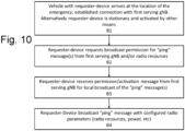
- Figure 10 shows a method performed by an apparatus of a requester device.
- a vehicle with the requester device arrives at a location of an emergency and the apparatus is configured to cause a connection to be established with an access node in a RAN.
- the access node may be a serving gNB of a 5G system.
- the requester device is stationary and is activated such that the apparatus of the requester device is configured to cause a connection to be established with an access node of the RAN. Where there is already a connection with the RAN, this step may be omitted in some embodiments.
- the apparatus of the requester device is configured to cause a request to be transmitted to the access node for broadcast permission for one or more ping messages and/or for the radio resources for the one or more ping messages.
- the apparatus of the requester device is configured to receive a message for access node.
- the message may be a permission or activation message for the local broadcast of the one or more ping messages.
- the apparatus of the requester device is configured to cause the requester device to broadcast the one or more ping message.
- the ping message may be broadcast with one or more configured radio parameters.
- the radio parameter may be radio resources, power and/or the like.
- Figure 11 shows a method performed by an apparatus of a device nearby to the requester device.
- the apparatus of the nearby device is configured to cause the nearby device to be in a mode in which the device is able to monitor radio resources for a ping broadcast message transmitted by the requester device.
- the mode may be an idle mode such as an RRC_IDLE mode or any other suitable mode.
- the radio resources may be pre-allocated or predefined radio resources. The app which is installed on the nearby device will cause the nearby device to be monitor for such message or to recognise those ping messages which are for that device.
- a ping broadcast message is received by the nearby device from the requester device.
- the apparatus of the nearby device determines based on the broadcast message and/or configuration of the application if a response should be sent. This determination may require input from the human user of the device.
- the apparatus of the nearby device may cause a message to be displayed on the display, requesting input from the human user. Depending on the input by the user or even the lack of input, this will be used by the apparatus to determine if a response is to be sent.
- the apparatus itself may be configured to determine if a response is to be sent without input from a human user.
- the apparatus may use AI (artificial intelligence) to determine if a response should be sent.
- a computer program may be used to determine if a response is to be sent.
- the apparatus is configured to cause the nearby device cause a message to be transmitted, via an access node, to the cloud based server.
- the message may be a preconfigured message.
- the message may indicate that the device is a discovered device.
- the device may be in any suitable mode such as a connected mode, for example such as a RRC_CONNECTED mode.
- FIG. 12 shows a method performed by an apparatus of a discovered device.
- a discovered device is a nearby device which has sent a message to the cloud based server indicating that the device is discovered.
- the apparatus of the discovered is configured to receive a message which is transmitted to the discovered device from the cloud based server.
- the message may comprise information indicating that help is needed.
- the information may indicate what help or assistance is required.
- the discovered device is configured to receive a connection request from the requester device, facilitated by the support of the cloud based server.
- the apparatus of the discovered device is configured to cause the discovered device to establish a connection with the requester device.
- This may be a unicast, broadcast or multicast connection.
- the connection may be via a RAN or via a device to device D2D connection.
- the apparatus of the cloud based server or the cloud based server will create a context in which to store packages from nearby/discovered devices.
- the stored data is represented by block E5.
- the information from the requester device may be that requester device is about to ping nearby devices and/or the resources that it is requesting.
- a stop criteria may be created for when to make a decision on sending data to the requester device. This may be using a timer or the like.
- the apparatus of the server or the server is configured to authenticate the requester device towards mobile network.
- the apparatus of the server or the server is configured to store data from nearby devices.
- the stored data is represented by block E5.
- the apparatus of the server or the server is configured to select one or more discovered device(s) that are fulfilling the requirements given by the requester device, for example distance, type of device, capabilities, etc. This may use stored data represented by block E5.
- Figure 14 shows a method a method performed by an apparatus of the cloud based server or the cloud based server, when there is a direct communication context.
- the apparatus of the cloud based server or the cloud based server is configured to cause information about non selected discovered devices to be deleted.
- Reference F3 schematically represents the stored data relating to the discovered devices. The data may be stored in a database.
- the apparatus of the cloud based server or the cloud based server will request that the selected discovered devices provide assistance and cause the requester device to be connected to the discovered Device(s) via the cloud based server.
- Figure 15 shows the setting up of a requester device to act as an "access node" so that the requester device can transmit ping messages.
- the server informs the network that an emergency session is required.
- the G2 Control server will inform requester that resources are available for the emergency network.
- a requester will enable access node, such as gNB, functionality for the emergency network.
- the network will inform devices to include the emergency network in a neighbour scan.
- control server informs requester that a session is created.
- the requester will send out one or more ping messages.
- the requester device when the connection to the one or more discovered device(s) are done, the requester device can disable the emergency access node network or keep it running if needed.
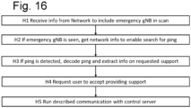
- information is received from the network to include the emergency access node, for example the emergency gNB, in its scans.
- the emergency access node for example the emergency gNB
- the discoverable device will get network information to enable searching for ping messages.
- the discoverable device will decode the ping information and extract information on the requested support.
- the discoverable device will request that the user accept providing of support. For example a message may be displayed and the user may be required to provide an input to that message.
- the discoverable device will communicate with the control server as previously described.
- the generation of the ping depends on the content of the ping and how many times it should be send in case the first ping does not result in any discovered devices.
- the requester should ask for resources for this one ping only.
- pings are required, one or more of the following options may be considered when the cloud based server informs the requester device about the pings required:
- the cloud based server can request a second (or more) ping(s) to be generated by the requester device.
- the second ping sequence may be handled like the first ping sequence.
- the number of pings for the same resource may be pre-defined by the cloud based server and handling the sequence of pings may be left for the requester device. In this embodiment, all pings in the sequence may be expected to be send out no matter if a discovered device covering the requested resources are found by the first ping.
- a ping can be divided into several sub groups, for paging subgroups.
- a ping message may comprise one or more of the following: A reference ID. This may be used to relate the actual ping request to a created context on the cloud based server. It may be used where more than one ping needs to be sent out for the nearby and discovered devices to know if they have already acted on an earlier ping with a same reference ID.
- a group ID This may be used to indicate which type of support is requested (i.e. doctor, medicine, nurse, etc.).
- a sub-group ID This is to be used for further precision of the group identifier (i.e. type of doctor, type of medicine, etc.).
- Event ID such as discussed previously.
- An event ID may be as an alternative to or in addition to one or more of the group ID and the sub-group ID.
- the ping message may comprise a plurality of group ID and/or a plurality of sub-group IDs and/or event IDs. This may for example if a plurality of different resources are required.
- different ping messages may be sent with the same reference ID but identifying one or more different group IDs and/or different sub-group IDs and/or event IDs.
- the ping message can include location data of the requester device and/or instructions to the nearby device that it should not answer in case it has a travel time greater than a given amount.
- This may be defined by the cloud based server for each context ID or may be set as a default or otherwise defined.
- the location data may comprise any suitable location data such as GNSS or GPS data.
- the response from a nearby devices to the cloud based server may contain one or more of the following:
- a signalling message is communicated between the nearby devices and a controller.
- the controller may for example be a cloud based server or any other suitable server.
- An acknowledgement message may be triggered by the received "ping" signal as a response.
- the acknowledgement message may be preconfigured.
- the devices which send this request from the controller may be considered as discovered devices. These discovered devices may be a sub-set of the nearby devices.
- the acknowledgement message may include information such as one or more of emergency help capabilities, location, owner availability, and/or the like
- a message may be sent between the controller and the discovered devices with which the controller can confirm the request.
- the controller may (in co-operation with the RAN) provide resource configuration to be used for direct communication between requester device and discovered device.
- the resource configuration may comprise radio resources where the discovered devices are to expect connection establishment with the requester-device when this is a relay or access node part of the RAN.
- a core network CN/application signalling message may be provided between the cloud based server and the discovered devices with which the human user of the discovered devices are informed on the emergency request; in case there is no direct human user (e.g. public defibrillator), the application at the discovered device can indicate/signal the emergency request.
- the requester-device may act as a local access node or simplified IAB/relay.
- the requester device may be limited to only broadcasting the "ping" message(s) on the preconfigured radio resources.
- the requester device may need to be a requester device which allowed to be such a device.
- the cloud based server may be configured to control the registration and collection of the requests between the discovered devices and the requester-device.
- the server device may be automatically controlled and/or user controlled.
- the server may provide the information and/or capabilities to setup a connection between requester device and discovered device.
- the communication can be established in any suitable way.
- the communication can be established as a standard IP traffic (voice and/or messages) connection and/or as D2D (device to device) for direct connection between requester device and discovered device or in any other suitable manner.
- the cloud based server may be responsible for selecting which of the responding nearby devices should be contacted for potentially becoming discovered devices.
- Several criteria can be considered for the cloud based server to be used for this. One or more of the following criteria may be taken into account:
- the cloud based server will receive feedback from several nearby devices. In such cases the cloud based server may have to do a stricter selection.
- One or more of the following options may be used to reduce the number of found nearby devices in areas (i.e. a city centre or the like) where it is expected the ping would reach a high number of nearby devices:
- nothing will be stored in the cloud based server for later use. For example, once the communication between the requester device and discovered device(s) are established by the cloud based server, the emergency application server will delete all information/logs about the communication. Alternatively or additionally, the data is deleted once an indication has been received that the event is completed and/or after a given amount of time. This may ensure that privacy of the detected device users is kept.
- Embodiments are not limited to previously described examples which are provided only as possible illustrative examples. Other embodiments may be applied where there is a situation requiring detection and identification of nearby devices. This may potentially be in emergency scenarios but other embodiments may have application in any other suitable scenario. For example, some embodiments may be used in IIOT or IOT scenarios to allow one IOT device to establish a connection with one or more other devices. The one or more other devices may be an IOT device or a non IOT device.
- care is taken to ensure that only approved "ping" stations will be able to trigger the local devices to contact the network.
- the nearby devices may be listening intermittently for a ping.
- the ping may in some embodiments be transmitted for a given period of time such that the nearby devices may receive the ping, even when they are listening intermittently.
- Some embodiments may provide one or more advantages. Some embodiments may provide a reliable discovery mechanism for a requester-device to discover nearby devices with relevant emergency capabilities under the control of a RAN and a Cloud Based Server.
- the RAN network may be any suitable network.
- the RAN may be a 3GPP RAN.
- Some embodiments may provide a reliable communication channel between a requester-device and relevant nearby devices in an ad-hoc manner partly under the control of a RAN.
- Some embodiments may improve the chances for someone having a stroke/accident/heart attack and/or the like to survive due to shortened response time by the appropriate personnel. In some embodiments, only those nearby devices/users are triggered which are in the relevant geographical area of the emergency (requester-device).
- Some embodiments may be implemented without the need to have a global database of available fixed position devices in the cloud based server. However, other embodiments may make use of a global database of such devices.
- Some embodiments may be implemented without the need to have a global database of all discoverable devices which have installed the application required to be part of the overall system setup. However, other embodiments may make use of a global database of such devices. Some embodiments may provide the ability to get knowledge about low power devices (and optionally their associated users) in the vicinity of the emergency.
- Some embodiments may address privacy issues by deleting privacy related data from the cloud server after the end of communication. This may be dependent on the legislation in the jurisdiction in which embodiments are provided.
- An access node such a gNB may act as the requester device itself. This may, for example, be for larger events or condensed concentration of users. This may be used on a cruise ship, a train, a plane and/or in concerts.
- the cloud based server may support registration of nearby devices at events for a certain period of time and the contexts may allowed "survive" until the event is over. In this way, the cloud based server would be aware of potential support during the event (i.e. how many doctors might be attending the event)
- Some embodiments may be applied in the context of automatic incident detection.
- Some embodiments provide a method.
- the method may be performed by an apparatus.
- the apparatus may be a first device or provided in the first device.
- the first device may be a requester device.
- the apparatus may be as shown in Figure 5 .
- the method may comprise receiving first information about a context provided by a controller.
- the first information may be received from a base station,
- the method may further comprise causing a first device to transmit one or more ping messages to one or more second devices.
- the one or more ping messages may comprise information about said context which causes one or more second devices to reply to the controller.
- Some embodiments provide a method.
- the method may be performed by an apparatus.
- the apparatus may be a second device or provided in the second device.
- the second device may be a nearby device.
- the apparatus may be as shown in Figure 5 .
- the method may comprise receiving a ping message which is transmitted by a first device.
- the message may comprise information about a context associated with a controller.
- the method may further comprise causing a message to be transmitted to the controller using the context associated with the controller.
- Some embodiments provide a method.
- the method may be performed by an apparatus.
- the apparatus may be a controller or provided in the controller.
- the controller may be a cloud server.
- the apparatus may be as shown in Figure 5 .
- the method may comprise receiving a request for a context from a first device.
- the method may comprise causing a message to be transmitted from a controller to the first device via a base station.
- the message may comprise first information about the context.
- the method may comprise receiving one or more responses from one or more second devices using the context.
- the one or more responses may be to one or more ping messages transmitted by the first device.
- some embodiments may be implemented in hardware or special purpose circuits, software, logic or any combination thereof.
- some aspects may be implemented in hardware, while other aspects may be implemented in firmware or software which may be executed by a controller, microprocessor or other computing device, although embodiments are not limited thereto.
- firmware or software which may be executed by a controller, microprocessor or other computing device, although embodiments are not limited thereto. While various embodiments may be illustrated and described as block diagrams, flow charts, or using some other pictorial representation, it is well understood that these blocks, apparatus, systems, techniques or methods described herein may be implemented in, as non-limiting examples, hardware, software, firmware, special purpose circuits or logic, general purpose hardware or controller or other computing devices, or some combination thereof.
- the embodiments may be implemented by computer software stored in a memory and executable by at least one data processor of the involved entities or by hardware, or by a combination of software and hardware. Further in this regard it should be noted that any of the above procedures may represent program steps, or interconnected logic circuits, blocks and functions, or a combination of program steps and logic circuits, blocks and functions.
- the software may be stored on such physical media as memory chips, or memory blocks implemented within the processor, magnetic media such as hard disk or floppy disks, and optical media such as for example DVD and the data variants thereof, CD.
- the memory may be of any type suitable to the local technical environment and may be implemented using any suitable data storage technology, such as semiconductor based memory devices, magnetic memory devices and systems, optical memory devices and systems, fixed memory and removable memory.
- the data processors may be of any type suitable to the local technical environment, and may include one or more of general purpose computers, special purpose computers, microprocessors, digital signal processors (DSPs), application specific integrated circuits (ASIC), gate level circuits and processors based on multi core processor architecture, as non limiting examples.
- circuitry may be configured to perform one or more of the functions and/or method procedures previously described. That circuitry may be provided in the network entity and/or in the communications device and/or a server and/or a device.
- circuitry may refer to one or more or all of the following:
- circuitry also covers an implementation of merely a hardware circuit or processor (or multiple processors) or portion of a hardware circuit or processor and its (or their) accompanying software and/or firmware.
- circuitry also covers, for example integrated device.
Claims (13)
- Einrichtung, die im Gebrauch in einer ersten Vorrichtung bereitgestellt ist, wobei die Einrichtung Folgendes umfasst: mindestens einen Prozessor und mindestens einen Speicher, der einen Computerprogrammcode beinhaltet, wobei der mindestens eine Speicher und der Computerprogrammcode dazu ausgelegt sind, die Vorrichtung mit dem mindestens einen Prozessor mindestens zu Folgendem zu veranlassen:Veranlassen (S3) einer Anforderung von i) einem Kontext und ii) Funkressourcen zum Übertragen von Pingnachrichten, die via eine Basisstation zu einer Steuerung zu übertragen ist;in Reaktion auf die Anforderung Empfangen von ersten Informationen über den Kontext, die von der Steuerung bereitgestellt werden, und Empfangen von zweiten Informationen über zugeteilte Funkressourcen, wobei die ersten und die zweiten Informationen von der Basisstation empfangen werden; undVeranlassen (S9) der ersten Vorrichtung, eine oder mehrere Pingnachrichten unter Verwendung der zugeteilten Funkressourcen zu einer oder mehreren zweiten Vorrichtungen zu übertragen, wobei die eine oder die mehreren Pingnachrichten Informationen über den Kontext umfassen, der die eine oder die mehreren zweiten Vorrichtungen veranlassen, der Steuerung zu antworten,wobei jede Pingnachricht Informationen über eine Unterstützung umfasst, die von der einen oder den mehreren zweiten Vorrichtungen und/oder verknüpften Benutzern der einen oder der mehreren zweiten Vorrichtungen erforderlich ist.
- Einrichtung nach Anspruch 1, wobei der mindestens eine Speicher und der Computerprogrammcode dazu ausgelegt sind, mit dem mindestens einen Prozessor die Einrichtung zu Folgendem zu veranlassen:
Veranlassen einer Kommunikation zwischen der ersten Vorrichtung und einer oder mehreren der zweiten Vorrichtungen via die Steuerung, nachdem die Pingnachricht durch die jeweilige zweite Vorrichtung empfangen wurde. - Einrichtung, die im Gebrauch in einer zweiten Vorrichtung bereitgestellt ist, wobei die Einrichtung Folgendes umfasst: mindestens einen Prozessor und mindestens einen Speicher, der einen Computerprogrammcode beinhaltet, wobei der mindestens eine Speicher und der Computerprogrammcode dazu ausgelegt sind, die Vorrichtung mit dem mindestens einen Prozessor mindestens zu Folgendem zu veranlassen:Empfangen (S10) einer Pingnachricht, die von einer ersten Vorrichtung übertragen wird, wobei die Nachricht Informationen über einen mit einer Steuerung verknüpften Kontext umfasst, wobei die Pingnachricht Informationen über eine Unterstützung umfasst, die von den zweiten Vorrichtungen und/oder verknüpften Benutzern der zweiten Vorrichtung erforderlich ist;Bestimmen (S11), dass eine Unterstützung, die in der Pingnachricht angefordert wird, von der zweiten Vorrichtung und/oder verknüpften Benutzern der zweiten Vorrichtung bereitgestellt werden kann; undVeranlassen (S13), dass eine Nachricht unter Verwendung des mit der Steuerung verknüpften Kontextes zur Steuerung übertragen wird, wobei die Nachricht Informationen umfasst, die anzeigen, dass die angeforderte Unterstützung bereitgestellt werden kann.
- Einrichtung nach Anspruch 3, wobei der mindestens eine Speicher und der Computerprogrammcode dazu ausgelegt sind, mit dem mindestens einen Prozessor die Einrichtung zu Folgendem zu veranlassen:
Bestimmen, dass eine Unterstützung, die in der Pingnachricht angefordert wird, in Reaktion auf eine Eingabe, die von einem verknüpften Benutzer der Vorrichtung angefordert wird, bereitgestellt werden kann. - Einrichtung nach einem der Ansprüche 3 bis 4, wobei der mindestens eine Speicher und der Computerprogrammcode dazu ausgelegt sind, mit dem mindestens einen Prozessor die Einrichtung zu Folgendem zu veranlassen:
Veranlassen einer Kommunikation via die Steuerung zwischen der zweiten Vorrichtung und einer Vorrichtung, nachdem die Nachricht zur Steuerung übertragen wurde. - Vorrichtung nach einem der Ansprüche 3 bis 5, wobei die Informationen über eine Unterstützung eine Gruppenkennung und wahlweise eine oder mehrere Untergruppenkennungen umfassen.
- Vorrichtung nach einem der Ansprüche 3 bis 6, wobei die Pingnachricht mit der ersten Vorrichtung verknüpfte Standortinformationen umfasst.
- Einrichtung, die im Gebrauch in einer Steuerung bereitgestellt ist, wobei die Einrichtung Folgendes umfasst: mindestens einen Prozessor und mindestens einen Speicher, der einen Computerprogrammcode beinhaltet, wobei der mindestens eine Speicher und der Computerprogrammcode dazu ausgelegt sind, die Vorrichtung mit dem mindestens einen Prozessor mindestens zu Folgendem zu veranlassen:Empfangen (S3) einer Anforderung von i) einem Kontext und ii) Funkressourcen zum Übertragen von Pingnachrichten von einer ersten Vorrichtung;Veranlassen, dass eine Nachricht von der Steuerung via eine Basisstation zur ersten Vorrichtung übertragen wird, wobei die Nachricht Folgendes umfasst: erste Informationen über den Kontext und zweite Informationen über zugeteilte Funkressourcen für die erste Vorrichtung; undEmpfangen (S13) von einer oder mehreren Antworten von einer oder mehreren zweiten Vorrichtungen unter Verwendung des Kontextes, wobei die eine oder die mehreren Antworten auf eine oder mehrere Pingnachrichten erfolgen, die von der ersten Vorrichtung übertragen werden, wobei jede Pingnachricht Informationen über eine Unterstützung umfasst, die von der einen oder den mehreren zweiten Vorrichtungen und/oder verknüpften Benutzern der einen oder der mehreren zweiten Vorrichtungen erforderlich ist.
- Einrichtung nach Anspruch 8, wobei der mindestens eine Speicher und der Computerprogrammcode dazu ausgelegt sind, mit dem mindestens einen Prozessor die Einrichtung zu Folgendem zu veranlassen:
Bestimmen auf Basis der einen oder der mehreren Antworten, mit welcher einen oder mehreren zweiten Vorrichtungen die Steuerung via eine oder mehrere Basisstationen kommunizieren soll. - System, das Folgendes umfasst:
eine Steuerung, eine erste Vorrichtung und eine oder mehrere zweite Vorrichtungen, wobei die Steuerung, die erste Vorrichtung und die eine oder die mehreren zweiten Vorrichtungen derart ausgelegt sind, dass:die erste Vorrichtung dazu ausgelegt ist, eine Anforderung von Folgendem zu übertragen (S3): i) einem Kontext und ii) Funkressourcen zum Übertragen von Pingnachrichten via eine Basisstation zur Steuerung sowie erste Informationen über den angeforderten Kontext und zweite Informationen über zugeteilte Funkressourcen für die erste Vorrichtung via die Basisstation von der Steuerung zu empfangen;die erste Vorrichtung dazu ausgelegt ist, eine oder mehrere Pingnachrichten unter Verwendung der zugeteilten Funkressourcen zu der einen oder den mehreren zweiten Vorrichtungen zu übertragen (S9), wobei die eine oder die mehreren Pingnachrichten Informationen über den angeforderten Kontext und Informationen über eine Unterstützung umfassen, die von der einen oder den mehreren zweiten Vorrichtungen und/oder verknüpften Benutzern der einen oder der mehreren zweiten Vorrichtungen erforderlich ist; undeine oder mehrere zweite Vorrichtungen dazu ausgelegt sind, der Steuerung unter Verwendung des angeforderten Kontextes zu antworten (S13), wobei die Antworten Informationen umfassen, die anzeigen, dass die angeforderte Unterstützung bereitgestellt werden kann. - Verfahren, das Folgendes umfasst:Veranlassen (S3) einer Anforderung von i) einem Kontext und ii) Funkressourcen zum Übertragen von Pingnachrichten, die via eine Basisstation zu einer Steuerung zu übertragen ist;in Reaktion auf die Anforderung Empfangen von ersten Informationen über den Kontext, die von der Steuerung bereitgestellt werden, und Empfangen von zweiten Informationen über zugeteilte Funkressourcen, wobei die ersten und die zweiten Informationen von der Basisstation empfangen werden; undVeranlassen (S9) einer ersten Vorrichtung, eine oder mehrere Pingnachrichten unter Verwendung der zugeteilten Funkressourcen zu einer oder mehreren zweiten Vorrichtungen zu übertragen, wobei die eine oder die mehreren Pingnachrichten Informationen über den Kontext umfassen, der die eine oder die mehreren zweiten Vorrichtungen veranlassen, der Steuerung zu antworten,wobei jede Pingnachricht Informationen über eine Unterstützung umfasst, die von der einen oder den mehreren zweiten Vorrichtungen und/oder verknüpften Benutzern der einen oder der mehreren zweiten Vorrichtungen erforderlich ist.
- Verfahren, das Folgendes umfasst:Empfangen (S10) einer Pingnachricht, die von einer ersten Vorrichtung übertragen wird, wobei die Nachricht Informationen über einen mit einer Steuerung verknüpften Kontext umfasst, wobei jede Pingnachricht Informationen über eine Unterstützung umfasst, die von der einen oder den mehreren zweiten Vorrichtungen und/oder verknüpften Benutzern der einen oder den mehreren zweiten Vorrichtungen erforderlich ist;Bestimmen (S11), dass eine Unterstützung, die in der Pingnachricht angefordert wird, von der zweiten Vorrichtung und/oder verknüpften Benutzern der zweiten Vorrichtung bereitgestellt werden kann; undVeranlassen (S13), dass eine Nachricht unter Verwendung des mit der Steuerung verknüpften Kontextes zur Steuerung übertragen wird, wobei die Nachricht Informationen umfasst, die anzeigen, dass die angeforderte Unterstützung bereitgestellt werden kann.
- Verfahren, das Folgendes umfasst:Empfangen (S3) einer Anforderung von i) einem Kontext und ii) Funkressourcen zum Übertragen von Pingnachrichten von einer ersten Vorrichtung;Veranlassen, dass eine Nachricht von einer Steuerung via eine Basisstation zur ersten Vorrichtung übertragen wird, wobei die Nachricht erste Informationen über den Kontext und zweite Informationen über zugeteilte Funkressourcen für die erste Vorrichtung umfasst; undEmpfangen (S13) von einer oder mehreren Antworten von einer oder mehreren zweiten Vorrichtungen unter Verwendung des Kontextes, wobei die eine oder die mehreren Antworten auf eine oder mehrere Pingnachrichten erfolgen, die von der ersten Vorrichtung übertragen werden,wobei jede Pingnachricht Informationen über eine Unterstützung umfasst, die von der einen oder den mehreren zweiten Vorrichtungen und/oder verknüpften Benutzern der einen oder der mehreren zweiten Vorrichtungen erforderlich ist.
Applications Claiming Priority (1)
| Application Number | Priority Date | Filing Date | Title |
|---|---|---|---|
| FI20205314 | 2020-03-30 |
Publications (2)
| Publication Number | Publication Date |
|---|---|
| EP3890365A1 EP3890365A1 (de) | 2021-10-06 |
| EP3890365B1 true EP3890365B1 (de) | 2023-12-13 |
Family
ID=75223115
Family Applications (1)
| Application Number | Title | Priority Date | Filing Date |
|---|---|---|---|
| EP21164774.8A Active EP3890365B1 (de) | 2020-03-30 | 2021-03-25 | Vorrichtung, verfahren und computerprogramm |
Country Status (2)
| Country | Link |
|---|---|
| US (1) | US11849509B2 (de) |
| EP (1) | EP3890365B1 (de) |
Family Cites Families (19)
| Publication number | Priority date | Publication date | Assignee | Title |
|---|---|---|---|---|
| US8208891B2 (en) * | 2009-05-01 | 2012-06-26 | At&T Intellectual Property I, L.P. | Methods and systems for relaying out of range emergency information |
| US8958815B2 (en) * | 2010-02-12 | 2015-02-17 | Broadcom Corporation | Method and system for characterizing location and/or range based on transmit power |
| US8509105B2 (en) * | 2010-06-23 | 2013-08-13 | Nokia Corporation | Method and apparatus for device-to-device network coordination |
| US8639266B2 (en) * | 2012-04-18 | 2014-01-28 | Google Inc. | Using peer devices to locate a mobile device |
| WO2013169974A1 (en) * | 2012-05-11 | 2013-11-14 | Interdigital Patent Holdings, Inc. | Context-aware peer-to-peer communication |
| US9042823B2 (en) * | 2012-06-07 | 2015-05-26 | Nokia Corporation | Method, apparatus, and computer program product for wireless short-range communication disconnection |
| US9049645B2 (en) * | 2012-07-20 | 2015-06-02 | Qualcomm Incorporated | WAN assisted monitoring and communications methods and apparatus for communications devices |
| US9420026B2 (en) * | 2012-10-31 | 2016-08-16 | At&T Intellectual Property I, L.P. | Distributing communication of a data stream among multiple devices |
| WO2014130091A1 (en) * | 2013-02-22 | 2014-08-28 | Intel IP Corporation | Systems and methods for access network selection and traffic routing |
| CN105612732A (zh) | 2013-07-10 | 2016-05-25 | 康维达无线有限责任公司 | 上下文感知邻近服务 |
| US9980173B2 (en) * | 2014-02-10 | 2018-05-22 | Lg Electronics Inc. | Method and apparatus for indicating QoS of D2D data in wireless communication system |
| US9628485B2 (en) * | 2014-08-28 | 2017-04-18 | At&T Intellectual Property I, L.P. | Facilitating peering between devices in wireless communication networks |
| US10085143B2 (en) * | 2016-09-30 | 2018-09-25 | Qnexis Inc. | System for managing organizational emergencies and coordinating emergency responses |
| EP3613231B1 (de) * | 2017-04-17 | 2022-10-12 | Apple Inc. | Gruppenbasierter kontext und sicherheit für massive internet-der-dinge-vorrichtungen |
| WO2018202798A1 (en) * | 2017-05-04 | 2018-11-08 | Fraunhofer-Gesellschaft zur Förderung der angewandten Forschung e.V. | UE GROUPS, UE GROUP MANAGER UEs AND UE GROUP MEMBER UEs |
| CN109478179A (zh) * | 2017-05-09 | 2019-03-15 | 诺基亚美国公司 | IoT设备连接、发现和联网 |
| US10375555B2 (en) * | 2017-09-08 | 2019-08-06 | At&T Intellectual Property I, L.P. | Disaster event management |
| US11957925B2 (en) * | 2018-06-28 | 2024-04-16 | Ositech Communications Inc. | System and method for managing a defibrillator |
| US11334388B2 (en) * | 2018-09-27 | 2022-05-17 | Amber Solutions, Inc. | Infrastructure support to enhance resource-constrained device capabilities |
-
2021
- 2021-03-25 EP EP21164774.8A patent/EP3890365B1/de active Active
- 2021-03-30 US US17/301,293 patent/US11849509B2/en active Active
Also Published As
| Publication number | Publication date |
|---|---|
| EP3890365A1 (de) | 2021-10-06 |
| US20210307112A1 (en) | 2021-09-30 |
| US11849509B2 (en) | 2023-12-19 |
Similar Documents
| Publication | Publication Date | Title |
|---|---|---|
| US11770873B2 (en) | Method for keeping mobile initiated connection only mode user equipment in connected mode | |
| US11792730B2 (en) | Network slice-available area information acquisition method | |
| US20230379669A1 (en) | Multicast and broadcast services in 5g networks for iot applications | |
| CN109644330B (zh) | 用于通过使用切片向终端提供网络服务的方法和装置 | |
| US8874710B2 (en) | Access network discovery | |
| WO2017125025A1 (zh) | 寻呼的方法、装置、系统及存储介质 | |
| US10045283B2 (en) | Method and system of providing small cell information to user equipments in a heterogeneous network environment | |
| US11297680B2 (en) | Method and apparatus for handling emergency services in a wireless network | |
| US20220377659A1 (en) | Network Slice Aware Cell Selection | |
| Doumiati et al. | A framework for LTE-A proximity-based device-to-device service registration and discovery | |
| US20220303884A1 (en) | Radio Access Network Connectivity Enhancements for Network Slicing | |
| CN115362699A (zh) | 无线通信系统中根据用户设备策略应用的会话管理方法 | |
| EP3890365B1 (de) | Vorrichtung, verfahren und computerprogramm | |
| US20220361093A1 (en) | Network Slice Admission Control (NSAC) Discovery and Roaming Enhancements | |
| WO2012089161A1 (zh) | 异常状态下用户的接入方法、装置和一种通信系统 | |
| CN113383564A (zh) | 控制通信网络的操作模式 | |
| US10306701B2 (en) | User discovery method, user equipment, and proximity service function entity | |
| US20230309043A1 (en) | Methods and systems for handling ue radio capability (urc) information | |
| WO2023071977A1 (zh) | 通信方法和装置 | |
| EP4304248A1 (de) | Verfahren zur übertragung von kontext und kommunikationsvorrichtung | |
| US20200195576A1 (en) | Technique for Providing Content Via a Mobile Communications Network | |
| WO2024032041A1 (zh) | 通信方法和通信装置 | |
| WO2023246431A1 (zh) | 一种通信方法和装置 | |
| WO2023215351A1 (en) | Enabling localized services in hosting network | |
| KR20230098301A (ko) | Amf 재할당을 관리하는 방법 및 장치 |
Legal Events
| Date | Code | Title | Description |
|---|---|---|---|
| PUAI | Public reference made under article 153(3) epc to a published international application that has entered the european phase |
Free format text: ORIGINAL CODE: 0009012 |
|
| STAA | Information on the status of an ep patent application or granted ep patent |
Free format text: STATUS: THE APPLICATION HAS BEEN PUBLISHED |
|
| AK | Designated contracting states |
Kind code of ref document: A1 Designated state(s): AL AT BE BG CH CY CZ DE DK EE ES FI FR GB GR HR HU IE IS IT LI LT LU LV MC MK MT NL NO PL PT RO RS SE SI SK SM TR |
|
| STAA | Information on the status of an ep patent application or granted ep patent |
Free format text: STATUS: REQUEST FOR EXAMINATION WAS MADE |
|
| 17P | Request for examination filed |
Effective date: 20220406 |
|
| RBV | Designated contracting states (corrected) |
Designated state(s): AL AT BE BG CH CY CZ DE DK EE ES FI FR GB GR HR HU IE IS IT LI LT LU LV MC MK MT NL NO PL PT RO RS SE SI SK SM TR |
|
| STAA | Information on the status of an ep patent application or granted ep patent |
Free format text: STATUS: EXAMINATION IS IN PROGRESS |
|
| 17Q | First examination report despatched |
Effective date: 20220630 |
|
| GRAP | Despatch of communication of intention to grant a patent |
Free format text: ORIGINAL CODE: EPIDOSNIGR1 |
|
| STAA | Information on the status of an ep patent application or granted ep patent |
Free format text: STATUS: GRANT OF PATENT IS INTENDED |
|
| INTG | Intention to grant announced |
Effective date: 20230706 |
|
| GRAS | Grant fee paid |
Free format text: ORIGINAL CODE: EPIDOSNIGR3 |
|
| GRAA | (expected) grant |
Free format text: ORIGINAL CODE: 0009210 |
|
| STAA | Information on the status of an ep patent application or granted ep patent |
Free format text: STATUS: THE PATENT HAS BEEN GRANTED |
|
| AK | Designated contracting states |
Kind code of ref document: B1 Designated state(s): AL AT BE BG CH CY CZ DE DK EE ES FI FR GB GR HR HU IE IS IT LI LT LU LV MC MK MT NL NO PL PT RO RS SE SI SK SM TR |
|
| REG | Reference to a national code |
Ref country code: GB Ref legal event code: FG4D |
|
| REG | Reference to a national code |
Ref country code: CH Ref legal event code: EP |
|
| REG | Reference to a national code |
Ref country code: DE Ref legal event code: R096 Ref document number: 602021007569 Country of ref document: DE |
|
| REG | Reference to a national code |
Ref country code: IE Ref legal event code: FG4D |
|
| PG25 | Lapsed in a contracting state [announced via postgrant information from national office to epo] |
Ref country code: GR Free format text: LAPSE BECAUSE OF FAILURE TO SUBMIT A TRANSLATION OF THE DESCRIPTION OR TO PAY THE FEE WITHIN THE PRESCRIBED TIME-LIMIT Effective date: 20240314 |
|
| REG | Reference to a national code |
Ref country code: LT Ref legal event code: MG9D |
|
| PG25 | Lapsed in a contracting state [announced via postgrant information from national office to epo] |
Ref country code: LT Free format text: LAPSE BECAUSE OF FAILURE TO SUBMIT A TRANSLATION OF THE DESCRIPTION OR TO PAY THE FEE WITHIN THE PRESCRIBED TIME-LIMIT Effective date: 20231213 |
|
| REG | Reference to a national code |
Ref country code: NL Ref legal event code: MP Effective date: 20231213 |
|
| PG25 | Lapsed in a contracting state [announced via postgrant information from national office to epo] |
Ref country code: ES Free format text: LAPSE BECAUSE OF FAILURE TO SUBMIT A TRANSLATION OF THE DESCRIPTION OR TO PAY THE FEE WITHIN THE PRESCRIBED TIME-LIMIT Effective date: 20231213 |
|
| PG25 | Lapsed in a contracting state [announced via postgrant information from national office to epo] |
Ref country code: LT Free format text: LAPSE BECAUSE OF FAILURE TO SUBMIT A TRANSLATION OF THE DESCRIPTION OR TO PAY THE FEE WITHIN THE PRESCRIBED TIME-LIMIT Effective date: 20231213 Ref country code: GR Free format text: LAPSE BECAUSE OF FAILURE TO SUBMIT A TRANSLATION OF THE DESCRIPTION OR TO PAY THE FEE WITHIN THE PRESCRIBED TIME-LIMIT Effective date: 20240314 Ref country code: ES Free format text: LAPSE BECAUSE OF FAILURE TO SUBMIT A TRANSLATION OF THE DESCRIPTION OR TO PAY THE FEE WITHIN THE PRESCRIBED TIME-LIMIT Effective date: 20231213 Ref country code: BG Free format text: LAPSE BECAUSE OF FAILURE TO SUBMIT A TRANSLATION OF THE DESCRIPTION OR TO PAY THE FEE WITHIN THE PRESCRIBED TIME-LIMIT Effective date: 20240313 |
|
| PGFP | Annual fee paid to national office [announced via postgrant information from national office to epo] |
Ref country code: DE Payment date: 20240130 Year of fee payment: 4 |