EP3890343A1 - Dispositif auditif - Google Patents
Dispositif auditif Download PDFInfo
- Publication number
- EP3890343A1 EP3890343A1 EP20166620.3A EP20166620A EP3890343A1 EP 3890343 A1 EP3890343 A1 EP 3890343A1 EP 20166620 A EP20166620 A EP 20166620A EP 3890343 A1 EP3890343 A1 EP 3890343A1
- Authority
- EP
- European Patent Office
- Prior art keywords
- transducer system
- earpiece
- switch
- vibration
- receivers
- Prior art date
- Legal status (The legal status is an assumption and is not a legal conclusion. Google has not performed a legal analysis and makes no representation as to the accuracy of the status listed.)
- Withdrawn
Links
Images
Classifications
-
- H—ELECTRICITY
- H04—ELECTRIC COMMUNICATION TECHNIQUE
- H04R—LOUDSPEAKERS, MICROPHONES, GRAMOPHONE PICK-UPS OR LIKE ACOUSTIC ELECTROMECHANICAL TRANSDUCERS; DEAF-AID SETS; PUBLIC ADDRESS SYSTEMS
- H04R1/00—Details of transducers, loudspeakers or microphones
- H04R1/10—Earpieces; Attachments therefor ; Earphones; Monophonic headphones
- H04R1/1041—Mechanical or electronic switches, or control elements
-
- H—ELECTRICITY
- H04—ELECTRIC COMMUNICATION TECHNIQUE
- H04R—LOUDSPEAKERS, MICROPHONES, GRAMOPHONE PICK-UPS OR LIKE ACOUSTIC ELECTROMECHANICAL TRANSDUCERS; DEAF-AID SETS; PUBLIC ADDRESS SYSTEMS
- H04R2225/00—Details of deaf aids covered by H04R25/00, not provided for in any of its subgroups
- H04R2225/57—Aspects of electrical interconnection between hearing aid parts
-
- H—ELECTRICITY
- H04—ELECTRIC COMMUNICATION TECHNIQUE
- H04R—LOUDSPEAKERS, MICROPHONES, GRAMOPHONE PICK-UPS OR LIKE ACOUSTIC ELECTROMECHANICAL TRANSDUCERS; DEAF-AID SETS; PUBLIC ADDRESS SYSTEMS
- H04R2225/00—Details of deaf aids covered by H04R25/00, not provided for in any of its subgroups
- H04R2225/59—Arrangements for selective connection between one or more amplifiers and one or more receivers within one hearing aid
-
- H—ELECTRICITY
- H04—ELECTRIC COMMUNICATION TECHNIQUE
- H04R—LOUDSPEAKERS, MICROPHONES, GRAMOPHONE PICK-UPS OR LIKE ACOUSTIC ELECTROMECHANICAL TRANSDUCERS; DEAF-AID SETS; PUBLIC ADDRESS SYSTEMS
- H04R2225/00—Details of deaf aids covered by H04R25/00, not provided for in any of its subgroups
- H04R2225/61—Aspects relating to mechanical or electronic switches or control elements, e.g. functioning
-
- H—ELECTRICITY
- H04—ELECTRIC COMMUNICATION TECHNIQUE
- H04R—LOUDSPEAKERS, MICROPHONES, GRAMOPHONE PICK-UPS OR LIKE ACOUSTIC ELECTROMECHANICAL TRANSDUCERS; DEAF-AID SETS; PUBLIC ADDRESS SYSTEMS
- H04R2420/00—Details of connection covered by H04R, not provided for in its groups
- H04R2420/03—Connection circuits to selectively connect loudspeakers or headphones to amplifiers
Definitions
- the invention relates to a transducer system for a hearing device.
- Hearing devices such as hearing aids may comprise receivers to notify users about issues such as low battery, program change, volume control, phone calls etc. with acoustic events such as beep tones, ring tones, voice messages etc.
- Vibration motors or actuators may provide the means to do so.
- the object is achieved by a transducer system according to claim 1.
- the term receiver is used to refer to a loud speaker.
- a transducer system for a hearing device comprises an electromechanical component with a movable mass and a circuit configured to switch the transducer system between a first state, in which the transducer system is configured as an acoustic element, and a second state, in which the transducer system is configured as a vibration source.
- the transducer system In the first state, the transducer system may be configured to have a small or minimal vibration output and to primarily output audio signals.
- the transducer system In the second state, the transducer system may be configured to have a high or maximum vibration output while still being capable of outputting audio signals.
- the electromechanical component is at least one receiver comprising the movable mass, in particular a membrane of said receiver.
- the electromechanical component is an active vent and the movable mass is a closure member of the said active vent.
- Active vents are electrically controllable mechanical vents to open and close a venting canal in a hearing aid to either provide reduced occlusion effect while talking (opened vent) or improved noise isolation, feedback performance and superior sound quality for streaming e.g. music from other devices (closed vent).
- the vent is switched for different situations (e.g. talking, streaming music, being in noisy situations).
- known solutions of such vents they may be integrated in the receiver of a hearing aid, e.g. in an elongate spout in front of the receiver.
- the transducer comprises two receivers configured as a dual receiver coupled to each other in a way to allow for mutually cancelling vibrational forces by mechanical compensation of inertial forces of the movable masses, wherein the circuit is configured to switch off or short one of the receivers or to change an electrical polarity of one of the receivers.
- An additional vibration device in the form of a second receiver is not needed, so that additional space in the earpiece is not required.
- the proposed double function of a dual receiver enables many possibilities to improve wearing comfort during fitting and during daily use.
- vibration measurements are useful for several monitoring applications like seal control or hardware check.
- a double receiver doesn't increase the volume of the earpiece as if a separate vibrator would be used.
- the circuit comprises at least one switch.
- the receivers are electrically connected to each other in series or in parallel.
- the circuit comprises two switches configured to be switched at the same time.
- the two switches may be coupled to each other to form a pole changeover switch to reverse a polarity.
- the at least one switch is an electronic switch or a mechanical switch.
- the circuit comprises:
- an earpiece for a hearing device comprises a shell or dome and a receiver configured to emit sound through a channel in the shell or dome into an ear canal, further comprising:
- a frequency of the vibration is in a range from 5 Hz to 150 Hz, in particular 10 Hz to 100 Hz, 10 Hz to 80 Hz, 10 Hz to 60 Hz or 10 Hz to 40 Hz.
- the frequency is adjustable.
- the ear piece is part of a hearing device.
- the hearing device is configured as a hearing aid.
- a vibration is generated to:
- the event is at least one of: loss of connectivity or connectivity detected, a call, low battery, rapid health change, in particular breathing or blood sugar limit, an approaching car or person talking, an alarm, a diary schedule.
- the event is a talking person approaching, wherein the direction, from which the talking person is approaching, is determined by a sound localisation algorithm, wherein said direction is indicated by a vibrating burst in the respective ear.
- Hearing aids may have integrated vibration sensors, either for health monitoring purposes or for voice sensing purposes.
- many diagnostic or monitoring applications based on vibrations and mechanical impedance quantities are possible. For example the interaction of ear piece and skin may be measured to detect a loose or a tight seal, to judge the correct softness of a dome or to determine the optimum softness of a shell.
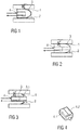
- Figure 1 is a schematic sectional view of an ear canal 1 with an inserted earpiece 2 of a hearing device, wherein the earpiece 2 comprises a hard shell 3.
- Figure 2 is a schematic sectional view of an ear canal 1 with an inserted earpiece 2 of a hearing device, wherein the earpiece 2 comprises a soft shell 3.
- Figure 3 is a schematic sectional view of an ear canal 1 with an inserted earpiece 2 of a hearing device, wherein the earpiece 2 comprises a shell 3 with a dome 3.1.
- a transducer system is shown in the form of a single receiver 4, i.e. a speaker, with normally unwanted vibrational force excitation.
- earpiece 2 and skin may be measured to detect a loose or a tight seal, to judge the correct softness of a dome 3.1 or to determine the optimum softness of a shell 3.
- Figure 4 is a schematic view of a dual receiver 4.1, 4.2.
- hearing aids may have dual receivers 4.1, 4.2 implemented to reduce these vibrational forces by mechanical compensation of the mass forces.
- the forces can be doubled by changing the electrical polarity of one of the two receivers 4.1, 4.2.
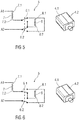
- FIG. 5 is a schematic view of a circuit 5 for changing the electrical polarity in a first state, wherein the receivers 4.1, 4.2 are connected in series.
- the same pair of receivers 4.1, 4.2 can be transformed from an acoustic source with minimal vibration output to a vibration source with maximum vibration output.
- This is performed by two switches 6.1, 6.2 as shown in Figure 5 .
- the receivers 4.1, 4.2 are represented by a first coil 7 or inductivity and a second coil 8 or inductivity.
- the switches 6.1, 6.2 may be electronic switches, e.g. switching transistors like the output stage of the hearing device, or mechanical switches in the form of a relay.
- the switches 6.1, 6.2 are configured as a turn-over switch with both switches 6.1, 6.2 coupled to be switched at the same time.
- a first terminal 7.1 of the first coil 7 is connected to a first audio line A1 and a second terminal 7.2 thereof is connected to the switch 6.1.
- the switch 6.1 connects the first coil 7 to a first terminal 8.1 of the second coil 8, while the second terminal 8.2 of the second coil 8 is connected to a second audio line A2.
- the two coils 7, 8 are thus connected in series with the second terminal 7.2 of the first coil 7 connected to the first terminal 8.1 of the second coil 8.
- Figure 6 shows the circuit 5 of figure 5 switched into a second state.
- the switches 6.1, 6.2 have been switched so that the second terminal 7.2 of the first coil 7 is connected to the second terminal 8.2 of the second coil 8 by the switch 6.1, while the first terminal 8.1 of the second coil 8 is connected to the second audio line A2.
- the two coils 7, 8 are thus connected in series with the second terminal 7.2 of the first coil 7 connected to the second terminal 8.2 of the second coil 8.
- the first state may represent a normal operation mode in which vibration forces are compensated by the receivers 4.1, 4.2 mutually cancelling the vibrations out.
- the second state may represent a vibration mode in which vibration forces of the receivers 4.1, 4.2 are superposed to double.
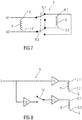
- FIG. 7 is a schematic view of an alternative embodiment of a circuit 5 for changing the electrical polarity, wherein the receivers 4.1, 4.2 are connected in parallel.
- the same pair of receivers 4.1, 4.2 can be transformed from an acoustic source with minimal vibration output to a vibration source with maximum vibration output.
- This is performed by two switches 6.1, 6.2 as shown in Figure 7 .
- the receivers 4.1, 4.2 are represented by a first coil 7 or inductivity and a second coil 8 or inductivity.
- the switches 6.1, 6.2 may be electronic switches, e.g. switching transistors like the output stage of the hearing device, or mechanical switches in the form of a relay.
- the switches 6.1, 6.2 are configured as a pole changeover switch with both switches 6.1, 6.2 coupled to be switched at the same time.
- a first terminal 7.1 of the first coil 7 is connected to a first audio line A1 and to the switch 6.1, whereas and a second terminal 7.2 of the first coil 7 is connected a second audio line A2 and to the switch 6.2.
- the switch 6.1 connects the first terminal 7.1 of the first coil 7 to a first terminal 8.1 of the second coil 8, while the switch 6.2 connects the second terminal 8.2 of the second coil 8 to the second audio line A2 and to the second terminal 7.2 of the first coil 7.
- the two coils 7, 8 are thus connected in parallel with the second terminal 7.2 of the first coil 7 connected to the second terminal 8.2 of the second coil 8.
- the switches 6.1, 6.2 are switched into a second state (not shown), in which the switch 6.1 connects the first terminal 7.1 of the first coil 7 to the second terminal 8.2 of the second coil 8, while the switch 6.2 connects the first terminal 8.1 of the second coil 8 to the second audio line A2 and to the second terminal 7.2 of the first coil 7.
- the two coils 7, 8 are thus connected in parallel (or anti-parallel relative to the first state) with the second terminal 7.2 of the first coil 7 connected to the first terminal 8.1 of the second coil 8.
- the first state may represent a normal operation mode in which vibration forces are compensated by the receivers 4.1, 4.2 mutually cancelling the vibrations out.
- the second state may represent a vibration mode in which vibration forces of the receivers 4.1, 4.2 are superposed to double.
- FIG 8 is a schematic view of an alternative embodiment of a circuit 5 for changing the electrical polarity, wherein the circuit 5 comprises an inverter 9 and two amplifiers 10, 11 and a selector switch 12.
- the same pair of receivers 4.1, 4.2 can be transformed from an acoustic source with minimal vibration output to a vibration source with maximum vibration output.
- the receivers 4.1, 4.2 are represented by a first coil 7 or inductivity and a second coil 8 or inductivity.
- the first coil 7 is controlled by the first amplifier 10 and the second coil 8 is controlled by the second amplifier 11, wherein the output of the first amplifier 10 may be connected to the first terminal 7.1 of the first coil 7 whose second terminal 7.2 is connected to ground G, wherein the output of the second amplifier 11 may be connected to the second terminal 8.2 of the second coil 8 whose first terminal 8.1 is connected to ground G.
- the audio signal transmitted by the audio lines A1, A2 in figures 5 to 7 may be an analogue signal or a digital signal
- the circuit 5 in figure 8 uses an audio signal D, e.g. a digital audio signal D, which is fixedly connected to the first amplifier 10 and to an input of the inverter 9 as well as to one input of the selector switch 12.
- the selector switch 12 is in a first state connecting the audio signal D to the second amplifier 11 so the coils 7, 8 may be in a normal operation mode in which vibration forces are compensated by the receivers 4.1, 4.2 mutually cancelling the vibrations out.
- the selector switch 12 When the selector switch 12 is switched over into a second state, it connects the output of the inverter 9 to the input of the second amplifier 11 so that the second coil 8 is fed with an inverse signal.
- the second state may represent a vibration mode in which vibration forces of the receivers 4.1, 4.2 are superposed to double.
- the circuit 5 may be modified by reversing the connections of one of the coils 7, 8 so that the first state, where the coils 7, 8 are in the normal operation mode in which vibration forces are compensated by the receivers 4.1, 4.2 mutually cancelling the vibrations out, would be when the selector switch 12 connects the output of the inverter 9 to the second amplifier 11, and the second state representing the vibration mode in which vibration forces of the receivers 4.1, 4.2 are superposed to double, would be when the selector switch 12 connects the audio signal D to the second amplifier 11.
- the amplifiers 10, 11 may be configured as a H-bridge, a class D amplifier or a digital/analogue converter respectively.
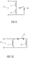
- Figure 9 is a schematic view of an alternative embodiment of a circuit 5, in which the coils 7, 8 are connected in series and a single switch 12 is arranged to selectively shorten the second coil 8, so that the first coil 7 gets more current (depending on the output impedance of a power amplifier); the total sound output is more or less constant.
- the remaining single receiver 4.1 produces vibrations which are no more compensated by the second receiver 4.2.
- Figure 10 is a schematic view of an alternative embodiment of a circuit 5, in which the coils 7, 8 are connected in parallel through a single switch 12.
- the switch 12 operates to interrupt the connection to the second coil 8 which leads to a similar effect as in Figure 9 .
- another single receiver could be used for vibration excitation only in addition to the dual receiver.
- a dual receiver system capable of selectively emitting a vibration can have different applications:
- the vibration can be used to notify events or states such as loss of connectivity or connectivity detected.
- the vibration can also be used in an air plane mode to notify a user from a call, a connection lost with another device (an accessory or second earpiece device), a low battery, and when the user does not want to be disturbed acoustically by a signal, e.g. during a conversation, a conference, a restaurant situation, a concert, in a theatre, etc.
- the vibration may also be used to notify a user of rapid health change, e.g. breathing, sugar limit etc.
- a user could be notified when something important is happening, e.g.
- a vibration may also be used to notify a user of a diary schedule, e.g. an appointment.
- the vibrator may be used together with an accelerometer to detect the correct position of an earpiece 2 in an ear canal 1.
- a reference measurement with a good placement of the earpiece 2 may be done by an audiologist, and a "good placement test" could be triggered by the user when he is at home, to test if the earpieces 2 are well placed in the ear canal 1, or to ensure that the earpieces 2 are not mixed up between left and right ear.
- a vibrator may be used to detect skin properties, as skin behaviour may differ before, during and/or after the vibration or skin properties may change over time, e.g. dryer skin may be correlated with elevated blood glucose levels.
- the vibration may be generated in one ear and measured in the other ear and the propagation of the vibration may be used to detect health changes.
- the vibration may be used to check if a component of the earpiece 2 shell 3 is loose, if there are problems with cerumen in a vent or in the shell 3 due to a change in the mass of the shell 3.
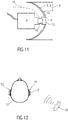
- Figure 11 is a schematic sectional view of an ear canal 1 with an inserted earpiece 2 of a hearing device, wherein the earpiece 2 comprises a shell 3 or dome 3.1 and a receiver 4 configured to emit sound through a channel 13 in the shell 3 or dome 3.1 into the ear canal 1.
- a vent opening 14 opens out into the channel 13 so as to bypass the receiver 4 through a ventilation path 15.
- a movable mass 16 is movably arranged within the channel 13 so as to selectively open or close the vent opening 14, e.g. by an electromagnetic actor (not shown).
- the vent opening 14 and the movable mass 16 form a so called active vent.
- the movable mass 16 may be switched forth and back at a relatively high rate of e.g. 5 Hz to 150 Hz, preferably 10 Hz to 100 Hz, 10 Hz to 80 Hz, 10 Hz to 60 Hz or 10 Hz to 40 Hz for a period of e.g. Is to 3s.
- the frequency to open and close the vent opening 14 depends upon multiple factors, such as e.g. the weight of the movable mass 16, the mechanical properties of any bearings of the active vent, the power consumption needed and interference generated by the vibration as well as subjective preferences. Thus it might even be adjustable or configurable either through the user, the health care professional or automatic depending on the use case.
- notification events are e.g. volume up/down, program change, incoming phone calls, low battery warnings etc., but also the 'translation' of acoustic events into haptic ones.
- FIG 12 is a schematic view of an exemplary scenario in which the vibration may be utilised.
- a hearing impaired person 17 is wearing a hearing device with an earpiece 2 placed in the right ear 18 which may be deaf or impaired.
- the earpiece 2 is capable of vibrating by being configured as in one of the above described embodiments.
- Another person 19 is approaching the hearing impaired person 17 from the right talking.
- the hearing impaired person 17 is not well able to locate sounds from different directions with their left ear 20 which may be healthy or less impaired, as human beings usually utilize the level differences and the different arrival times of a sound at both ears 18, 20 to determine an impinging sound direction.
- a sound localisation algorithm e.g.
- EP 1 307 761 B1 may be used by a control unit of the hearing device to determine if a sound originates from a certain direction, e.g. from the side of the right ear 18. If the direction of the sound from the talking person 19 has been identified, a short vibrating burst may be output indicating to the hearing impaired person 17 the impinging direction thus indicating in which direction they should turn their head.
- a user gets a haptic input stimulus in addition to the acoustic one, which is correlated with and contains relevant information to understand speech.
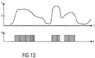
- Modulating white noise with the sound level envelope L of a speech signal makes the white noise understandable as speech.
- the speech signal envelope is known to contain sufficient or at least highly helpful information to understand speech.
- the switching frequency of the vibrator might get synchronized with e.g. the pitch frequency of a speech signal, thus providing even further information.
- the brain is highly adaptable, it can learn to interpret the haptic feedback and integrate it with the acoustic input into a better speech understanding.
- Modulation might happen in the simplest case with a threshold T on the signal envelope as shown in figure 13 over the time t, i.e. the vibration V may be generated once the sound signal exceeds the threshold T level. Further, the activation strength of the vent might get adapted according to the sound level envelope L in order to induce a stronger or weaker vibration. All these methods may be combined with each other.
- haptic versions might use an e.g. pressure inducing actuator in contact with the skin or a conventional vibration actuator.
Priority Applications (1)
| Application Number | Priority Date | Filing Date | Title |
|---|---|---|---|
| EP20166620.3A EP3890343A1 (fr) | 2020-03-30 | 2020-03-30 | Dispositif auditif |
Applications Claiming Priority (1)
| Application Number | Priority Date | Filing Date | Title |
|---|---|---|---|
| EP20166620.3A EP3890343A1 (fr) | 2020-03-30 | 2020-03-30 | Dispositif auditif |
Publications (1)
| Publication Number | Publication Date |
|---|---|
| EP3890343A1 true EP3890343A1 (fr) | 2021-10-06 |
Family
ID=70058168
Family Applications (1)
| Application Number | Title | Priority Date | Filing Date |
|---|---|---|---|
| EP20166620.3A Withdrawn EP3890343A1 (fr) | 2020-03-30 | 2020-03-30 | Dispositif auditif |
Country Status (1)
| Country | Link |
|---|---|
| EP (1) | EP3890343A1 (fr) |
Citations (7)
| Publication number | Priority date | Publication date | Assignee | Title |
|---|---|---|---|---|
| EP1307761A2 (fr) | 2000-08-11 | 2003-05-07 | Phonak Ag | Procede de localisation de direction et dispositif de localisation |
| EP2747455A2 (fr) * | 2012-12-19 | 2014-06-25 | Starkey Laboratories, Inc. | Soupape de purge de dispositif d'aide auditive |
| CN204190913U (zh) * | 2014-10-23 | 2015-03-04 | 刘洪川 | 防疲劳驾驶蓝牙耳机 |
| CN204761675U (zh) * | 2015-08-11 | 2015-11-11 | 金希平 | 一种耳机 |
| EP3041261A1 (fr) * | 2014-12-31 | 2016-07-06 | Skullcandy, Inc. | Ensembles de haut-parleurs pour la production passive de vibrations et dispositifs et procédés de casques d'écoute associés |
| WO2017049241A1 (fr) * | 2015-09-16 | 2017-03-23 | Taction Technology Inc. | Appareil et procédés pour spatialisation audio-tactile du son et perception des basses |
| CN208768276U (zh) * | 2018-10-17 | 2019-04-19 | 东莞市云仕电子有限公司 | 一种振动耳机 |
-
2020
- 2020-03-30 EP EP20166620.3A patent/EP3890343A1/fr not_active Withdrawn
Patent Citations (7)
| Publication number | Priority date | Publication date | Assignee | Title |
|---|---|---|---|---|
| EP1307761A2 (fr) | 2000-08-11 | 2003-05-07 | Phonak Ag | Procede de localisation de direction et dispositif de localisation |
| EP2747455A2 (fr) * | 2012-12-19 | 2014-06-25 | Starkey Laboratories, Inc. | Soupape de purge de dispositif d'aide auditive |
| CN204190913U (zh) * | 2014-10-23 | 2015-03-04 | 刘洪川 | 防疲劳驾驶蓝牙耳机 |
| EP3041261A1 (fr) * | 2014-12-31 | 2016-07-06 | Skullcandy, Inc. | Ensembles de haut-parleurs pour la production passive de vibrations et dispositifs et procédés de casques d'écoute associés |
| CN204761675U (zh) * | 2015-08-11 | 2015-11-11 | 金希平 | 一种耳机 |
| WO2017049241A1 (fr) * | 2015-09-16 | 2017-03-23 | Taction Technology Inc. | Appareil et procédés pour spatialisation audio-tactile du son et perception des basses |
| CN208768276U (zh) * | 2018-10-17 | 2019-04-19 | 东莞市云仕电子有限公司 | 一种振动耳机 |
Similar Documents
| Publication | Publication Date | Title |
|---|---|---|
| CN107278377B (zh) | 基于平衡电枢的阀 | |
| US6760457B1 (en) | Automatic telephone switch for hearing aid | |
| Dillon | Hearing aids | |
| KR101779641B1 (ko) | 보청기를 가진 개인 통신 장치 및 이를 제공하기 위한 방법 | |
| EP2640095B2 (fr) | Méthode d'appareillage d'une aide auditive avec contrôle actif de l'occlusion à un utilisateur | |
| CN106888414A (zh) | 具有闭塞耳朵的说话者的自身语音体验的控制 | |
| US11234087B2 (en) | Hearing device comprising an active vent and method for its operation | |
| EP1617705A2 (fr) | Prothèse auditive avec adaptation in-situ | |
| CN104822119B (zh) | 用于确定耳蜗死区的设备 | |
| CN112866890B (zh) | 一种入耳检测方法及系统 | |
| WO2007103950A2 (fr) | Système et méthode d'écoute d'auto-test programmable | |
| DK201770606A1 (en) | AN OCCLUSION CONROL SYSTEM FOR A HEARING INSTRUMENT AND A HEARING INSTRUMENT | |
| EP3213527A1 (fr) | Atténuation de l'occlusion de sa propre voix dans des casques | |
| US11589173B2 (en) | Hearing aid comprising a record and replay function | |
| EP3525489A1 (fr) | Procédé de montage d'un dispositif auditif selon les des besoins d'un utilisateur, dispositif de programmation et système d'écoute | |
| KR100809549B1 (ko) | 보청기 겸용 무선 헤드셋 및 그 제어방법 | |
| CN111988718B (zh) | 听力设备和用于运行听力设备的方法 | |
| EP3890343A1 (fr) | Dispositif auditif | |
| EP3072314B1 (fr) | Un procédé pour l'exploitation d'un system auditif pour l'établissement de coups de télépone ainsi qu'un system auditif correspondant | |
| EP4054209A1 (fr) | Dispositif auditif comprenant un suppresseur d'émissions actives | |
| US7248710B2 (en) | Embedded internet for hearing aids | |
| Dillon | Hearing Aids | |
| WO2023160275A9 (fr) | Procédé de traitement de signal sonore, et dispositif d'écouteur | |
| KR20030069471A (ko) | 음향 입출력장치 및 이를 적용한 마이크 일체형 이어폰 | |
| EP4250759A1 (fr) | Écouteur et son procédé de commande |
Legal Events
| Date | Code | Title | Description |
|---|---|---|---|
| PUAI | Public reference made under article 153(3) epc to a published international application that has entered the european phase |
Free format text: ORIGINAL CODE: 0009012 |
|
| STAA | Information on the status of an ep patent application or granted ep patent |
Free format text: STATUS: THE APPLICATION HAS BEEN PUBLISHED |
|
| AK | Designated contracting states |
Kind code of ref document: A1 Designated state(s): AL AT BE BG CH CY CZ DE DK EE ES FI FR GB GR HR HU IE IS IT LI LT LU LV MC MK MT NL NO PL PT RO RS SE SI SK SM TR |
|
| STAA | Information on the status of an ep patent application or granted ep patent |
Free format text: STATUS: THE APPLICATION IS DEEMED TO BE WITHDRAWN |
|
| 18D | Application deemed to be withdrawn |
Effective date: 20220407 |