EP3889988A1 - Protection device with u-shaped fuse element - Google Patents
Protection device with u-shaped fuse element Download PDFInfo
- Publication number
- EP3889988A1 EP3889988A1 EP21166221.8A EP21166221A EP3889988A1 EP 3889988 A1 EP3889988 A1 EP 3889988A1 EP 21166221 A EP21166221 A EP 21166221A EP 3889988 A1 EP3889988 A1 EP 3889988A1
- Authority
- EP
- European Patent Office
- Prior art keywords
- cavity
- housing
- component
- fuse element
- protection device
- Prior art date
- Legal status (The legal status is an assumption and is not a legal conclusion. Google has not performed a legal analysis and makes no representation as to the accuracy of the status listed.)
- Granted
Links
Images


Classifications
-
- H—ELECTRICITY
- H01—ELECTRIC ELEMENTS
- H01H—ELECTRIC SWITCHES; RELAYS; SELECTORS; EMERGENCY PROTECTIVE DEVICES
- H01H85/00—Protective devices in which the current flows through a part of fusible material and this current is interrupted by displacement of the fusible material when this current becomes excessive
- H01H85/02—Details
- H01H85/04—Fuses, i.e. expendable parts of the protective device, e.g. cartridges
- H01H85/05—Component parts thereof
- H01H85/055—Fusible members
- H01H85/08—Fusible members characterised by the shape or form of the fusible member
-
- H—ELECTRICITY
- H01—ELECTRIC ELEMENTS
- H01H—ELECTRIC SWITCHES; RELAYS; SELECTORS; EMERGENCY PROTECTIVE DEVICES
- H01H85/00—Protective devices in which the current flows through a part of fusible material and this current is interrupted by displacement of the fusible material when this current becomes excessive
- H01H85/02—Details
- H01H85/04—Fuses, i.e. expendable parts of the protective device, e.g. cartridges
- H01H85/041—Fuses, i.e. expendable parts of the protective device, e.g. cartridges characterised by the type
- H01H85/042—General constructions or structure of high voltage fuses, i.e. above 1000 V
-
- H—ELECTRICITY
- H01—ELECTRIC ELEMENTS
- H01H—ELECTRIC SWITCHES; RELAYS; SELECTORS; EMERGENCY PROTECTIVE DEVICES
- H01H85/00—Protective devices in which the current flows through a part of fusible material and this current is interrupted by displacement of the fusible material when this current becomes excessive
- H01H85/02—Details
- H01H85/04—Fuses, i.e. expendable parts of the protective device, e.g. cartridges
- H01H85/05—Component parts thereof
- H01H85/055—Fusible members
-
- H—ELECTRICITY
- H01—ELECTRIC ELEMENTS
- H01H—ELECTRIC SWITCHES; RELAYS; SELECTORS; EMERGENCY PROTECTIVE DEVICES
- H01H85/00—Protective devices in which the current flows through a part of fusible material and this current is interrupted by displacement of the fusible material when this current becomes excessive
- H01H85/02—Details
- H01H85/04—Fuses, i.e. expendable parts of the protective device, e.g. cartridges
- H01H85/05—Component parts thereof
- H01H85/165—Casings
-
- H—ELECTRICITY
- H01—ELECTRIC ELEMENTS
- H01H—ELECTRIC SWITCHES; RELAYS; SELECTORS; EMERGENCY PROTECTIVE DEVICES
- H01H85/00—Protective devices in which the current flows through a part of fusible material and this current is interrupted by displacement of the fusible material when this current becomes excessive
- H01H85/02—Details
- H01H85/04—Fuses, i.e. expendable parts of the protective device, e.g. cartridges
- H01H85/05—Component parts thereof
- H01H85/18—Casing fillings, e.g. powder
-
- H—ELECTRICITY
- H01—ELECTRIC ELEMENTS
- H01H—ELECTRIC SWITCHES; RELAYS; SELECTORS; EMERGENCY PROTECTIVE DEVICES
- H01H85/00—Protective devices in which the current flows through a part of fusible material and this current is interrupted by displacement of the fusible material when this current becomes excessive
- H01H85/02—Details
- H01H85/04—Fuses, i.e. expendable parts of the protective device, e.g. cartridges
- H01H85/05—Component parts thereof
- H01H85/18—Casing fillings, e.g. powder
- H01H85/185—Insulating members for supporting fusible elements inside a casing, e.g. for helically wound fusible elements
-
- H—ELECTRICITY
- H01—ELECTRIC ELEMENTS
- H01H—ELECTRIC SWITCHES; RELAYS; SELECTORS; EMERGENCY PROTECTIVE DEVICES
- H01H85/00—Protective devices in which the current flows through a part of fusible material and this current is interrupted by displacement of the fusible material when this current becomes excessive
- H01H85/02—Details
- H01H85/38—Means for extinguishing or suppressing arc
-
- H—ELECTRICITY
- H01—ELECTRIC ELEMENTS
- H01H—ELECTRIC SWITCHES; RELAYS; SELECTORS; EMERGENCY PROTECTIVE DEVICES
- H01H9/00—Details of switching devices, not covered by groups H01H1/00 - H01H7/00
- H01H9/30—Means for extinguishing or preventing arc between current-carrying parts
- H01H9/302—Means for extinguishing or preventing arc between current-carrying parts wherein arc-extinguishing gas is evolved from stationary parts
-
- H—ELECTRICITY
- H01—ELECTRIC ELEMENTS
- H01H—ELECTRIC SWITCHES; RELAYS; SELECTORS; EMERGENCY PROTECTIVE DEVICES
- H01H9/00—Details of switching devices, not covered by groups H01H1/00 - H01H7/00
- H01H9/30—Means for extinguishing or preventing arc between current-carrying parts
- H01H9/34—Stationary parts for restricting or subdividing the arc, e.g. barrier plate
- H01H9/36—Metal parts
-
- H—ELECTRICITY
- H01—ELECTRIC ELEMENTS
- H01H—ELECTRIC SWITCHES; RELAYS; SELECTORS; EMERGENCY PROTECTIVE DEVICES
- H01H85/00—Protective devices in which the current flows through a part of fusible material and this current is interrupted by displacement of the fusible material when this current becomes excessive
- H01H85/02—Details
- H01H85/38—Means for extinguishing or suppressing arc
- H01H2085/383—Means for extinguishing or suppressing arc with insulating stationary parts
-
- H—ELECTRICITY
- H01—ELECTRIC ELEMENTS
- H01H—ELECTRIC SWITCHES; RELAYS; SELECTORS; EMERGENCY PROTECTIVE DEVICES
- H01H85/00—Protective devices in which the current flows through a part of fusible material and this current is interrupted by displacement of the fusible material when this current becomes excessive
- H01H85/02—Details
- H01H85/38—Means for extinguishing or suppressing arc
- H01H2085/388—Means for extinguishing or suppressing arc using special materials
-
- H—ELECTRICITY
- H01—ELECTRIC ELEMENTS
- H01H—ELECTRIC SWITCHES; RELAYS; SELECTORS; EMERGENCY PROTECTIVE DEVICES
- H01H85/00—Protective devices in which the current flows through a part of fusible material and this current is interrupted by displacement of the fusible material when this current becomes excessive
- H01H85/02—Details
- H01H85/04—Fuses, i.e. expendable parts of the protective device, e.g. cartridges
- H01H85/05—Component parts thereof
- H01H85/165—Casings
- H01H85/175—Casings characterised by the casing shape or form
Definitions
- the disclosure relates generally to circuit protection devices, more particularly, to a protection device with a U-shaped fuse element.
- Fuses are commonly used as circuit protection devices. Fuses can provide electrical connections between sources of electrical power and circuit components to be protected. High-voltage, current-limiting fuses are used in a variety of applications including, for example, Electric Vehicles (EVs) and Hybrid-Electric Vehicles (HEVs). EV systems typically use much higher voltages and currents than non-EV automotive systems. Bus voltages for EV systems can be in the range of 600 volts DC or AC, and currents can be in the range of 300 amps. These high-voltage applications therefore require fuses capable of handling the increased energy and arcing associated with an opening of a fuse element within the fuse used for such applications.
- EVs Electric Vehicles
- HEVs Hybrid-Electric Vehicles
- Capable EV fuse products currently existing have limited mounting and wiring options.
- the assortment of shapes of overcurrent protection equipment and difficulties in wiring tends to result in inefficient use of space in limited areas.
- a protection device may include a housing defining a cavity, and a fuse element within the cavity.
- the fuse element may include a first component and a second component separated by a barrier, and wherein the first and second components are joined at a bridge.
- a fuse assembly may include a housing defining a cavity, and a fuse element within the cavity, wherein the fuse element includes a first component extending parallel to a second component, wherein the first and second components are joined at a bridge, and wherein the first and second components are separated by a barrier.
- a protection device may include a housing defining a cavity, and a fuse element within the cavity, wherein the fuse element includes a first component and a second component separated by a barrier and joined at a fusible bridge, and wherein the fuse element has an inverted U-shape.
- EV fuses are a relatively new type of fuse to the automotive market within the last decade or so. Historically, these fuses have roots in industrial fuse design and have been slowly progressing to a more automotive-friendly design as volumes ramp up. The industrial design is typically very limiting in attachment into the application, overall fuse construction/appearance, and robustness. This disclosure provides a more automotive-friendly design, e.g., in shape/construction, performance, and features.
- the overall construction of the fuse element may take on an inverted u-shape.
- the arc is forced outward and away from the two current paths of the u-shaped element due to electromagnetic forces (B-forces).
- B-forces electromagnetic forces
- the disclosure also considers the fact that the closer together the current paths are, the higher this B-force is. As such, the disclosure herein may provide a barrier to separate the two paths the u-shaped element and provide insulation and additional arc suppression.
- a highly endothermic material e.g., melamine or Polyamide 46 (PA46)
- PA46 Polyamide 46
- PA46 Polyamide 46
- Utilizing this material in other areas of the fuse construction may also help improve the arcing performance of the fuse, possibly allowing for the elimination of sand from high voltage fuses.
- An additional performance method for quenching the arc according to the present disclosure is to use a varied volume arc chamber. For example, as the arc consumes the current paths of the fuse element, the B-force forces the arc into a larger volume area, which reduces the energy of the arc not only by lengthening it, but by reducing the pressure. This is especially advantageous when designing a high voltage fuse without a filler material (e.g., sand).
- a filler material e.g., sand
- splitter plates may be added to the device, wherein the arc can be cooled down by adding non-current-carrying mass to the arc path.
- this can improve the arcing performance with sand or potentially allow for elimination of the sand entirely.
- packaging options may also be varied.
- plug-in terminals can be utilized due to the construction of the bottom fuse section.
- terminals can be formed and stamped with a hole for bolt-down applications.
- the terminals can be formed along the sides of the fuse body to work with soldered PCB applications or clamp-type connections. Similar to OHEV / 10EV, this type of construction can accept custom terminals that can be soldered to terminal stubs.
- another aspect of this disclosure is the addition of armor to enclose the fuse. Wrapping the high arc quenching material in a stronger material may allow more strength, thus keeping pressure inside of the fuse from escaping. This advantageously allows for a smaller footprint and reduces the use of arc-quenching material, which may be expensive.
- the exemplary device 100 may include a housing 102 defining an internal cavity 104.
- the housing 102 may include a base wall 106, a top wall 108, and a set of sidewalls 110.
- the various components of the housing 102 may be made of an insulating material, such as an insulating plastic, e.g., nylon, glass-filled nylon, polyester and polycarbonate.
- the base wall 106, the top wall 108, and the sidewalls 110 can be made of the same or different materials.
- the cavity 104 may include one or more circuit protection devices, e.g., fuses 114, disposed therein.
- the fuse 114 may include a fuse element 116 within the cavity 104, the fuse element 116 being formed from or comprised of any material having desirable electrically conductive properties.
- the fuse element 116 can be nickel, copper, tin, or an alloy or mixture comprising nickel, copper, silver, gold, or tin, or any combination thereof.
- the fuse element 116 may have an approximate thickness of between 5 and 20 mils (a mil being a thousandth of an inch).
- the fuse element 116 may include a first component 118 and a second component 120 separated by a barrier 122.
- the first and second components 118, 120 generally extend parallel to one another, forming an inverted U-shape.
- the first and second components 118, 120 may be joined at a bridge 128.
- the bridge 128 may include one or more weakened or thinned segments separated by perforations to form a set of fusible links. During an overcurrent event, the fusible links fail to prevent current from passing between the first and second components 118, 120.
- the first and second components 118, 120 may extend parallel to corresponding exterior surfaces of the barrier 122.
- the first and second components 118, 120 may be in direct contact with the barrier 122. Said another way, the fuse element 116 may wrap around the barrier 122.
- a first terminal 130 may be connected to the first component 118 and a second terminal 132 may be connected to the second component 120.
- the first and second terminals 130, 132 extend outside of the housing 102, through the base wall 106.
- the free ends of the first and second terminals 130, 132 may be formed as blades for connection as a plug-in fuse to the other electrical components.
- the cavity 104 may be filled with an arc suppressant material, such as silica, silicone, sand, or any combination thereof.
- An opening through the housing 102 may allow the cavity 104 to be filled with the arc suppressant material.
- the hole may be centered in the top wall 108 so that the arc suppressant material may evenly fill the cavity 104.
- the barrier 122 may extend between the first and second components 118, 120 of the fuse element 116.
- the barrier 122 and the first and second components 118, 120 may extend perpendicular to the base wall 106.
- the barrier 122 may be constructed from a high outgassing or endothermic materials, such as stainless steel or aluminum.
- the barrier 122 and the base wall 106 may be the same material.
- the barrier 122 is an arc barrier generally formed according to the shape of the fuse element 116.
- the exemplary device 200 may include a housing 202 defining an internal cavity 204.
- a u-shaped fuse element 216 may be disposed within the cavity 204.
- the housing 202 may include a base wall 206, a top wall 208, and a set of side walls 210.
- the housing 202 may further include an armor layer 240 extending into the cavity.
- the armor layer 240 may be formed along interior surfaces of the base wall 206, the top wall 208, and the side walls 210. In other embodiments, the armor layer 240 may additionally, or alternatively, be formed along one or more exterior surfaces of the housing 202.
- an interior surface 242 of the armor layer 240 may define the cavity 204.
- the cavity 204 may take on an inverted teardrop shape or profile.
- the shape of the cavity 204 keeps an arc volume 244 generally equidistant from the interior surfaces of the housing 202 to provide enhanced cooling and outgassing.
- the armor layer 240 may be a stainless steel.
- the cavity 204 may be filled with an arc suppressant material, such as silica, or sand.
- the device 300 may be the same or similar in certain aspects to the devices 100 and 200 described above. As such, only certain aspects of the device 300 may hereinafter be described for the sake of brevity.
- the device 300 may include a housing 302 defining an internal cavity 304.
- a u-shaped fuse element 316 may be disposed within the cavity 304.
- the housing 302 may include a base wall 306, a top wall 308, and a set of side walls 310.
- Extending into the cavity 304 may be a plurality of splitter plates 348.
- the splitter plates 348 may generally extend perpendicular to the top wall 308. During use, the splitter plates 348 split arcs into a series of smaller arcs of less voltage.
- the splitter plates 348 may be symmetrical on both sides of a centerline extending through a barrier 322.
- the splitter plates 348 can be made of any ferrous material, including, but not limited to, steel. More or fewer plates than shown can be used in other implementations.
- the size of splitter plates 348, and the spacing(s) between them can be chosen depending on the particular implementation, such as based on the overall size of the device 300 and/or the voltage or current that is expected to occur.
- the housing 302 may further include an armor layer 340 formed along interior surfaces thereof. Furthermore, the cavity 304 may be filled with an arc suppressant material, such as silica, or sand.
- an arc suppressant material such as silica, or sand.
- the exemplary device 400 may include a housing 402 defining an internal cavity 404.
- a u-shaped fuse element 416 may be disposed within the cavity 404.
- the housing 402 may include a base wall 406, a top wall 408, and a set of side walls 410.
- the housing 402 may further include an armor layer 440 extending towards the fuse element 416.
- the armor layer 440 may be formed along interior surfaces of the side walls 410 and the base wall 406. As shown, the armor layer 440 is not formed along the top wall 408.
- An interior surface 442 of the armor layer 440 may partially define the cavity 404.
- the armor layer 440 may be a stainless steel.
- the cavity 404 may be filled with an arc suppressant material, such as silica, or sand.
- a first terminal 530 and a second terminal 532 extend flat along a base wall 506 of a housing 502.
- Each of the first and second terminals 530, 532 may include openings (not shown) to receive a fastener.
- a first terminal 630 and a second terminal 632 extend along a base wall 606 and each sidewall 610 of a housing 602. The first and second terminals 530, 532 may be clampable.
- each of the expressions “at least one of A, B and C”, “at least one of A, B, or C”, “one or more of A, B, and C", “one or more of A, B, or C" and "A, B, and/or C” means A alone, B alone, C alone, A and B together, A and C together, B and C together, or A, B and C together.
- All directional references e.g., proximal, distal, upper, lower, upward, downward, left, right, lateral, longitudinal, front, back, top, bottom, above, below, vertical, horizontal, radial, axial, clockwise, and counterclockwise
- Connection references e.g., attached, coupled, connected, and joined
- connection references are to be construed broadly and may include intermediate members between a collection of elements and relative movement between elements unless otherwise indicated. As such, connection references do not necessarily infer that two elements are directly connected and in fixed relation to each other.
- identification references e.g., primary, secondary, first, second, third, fourth, etc. are not intended to connote importance or priority, but are used to distinguish one feature from another.
- the drawings are for purposes of illustration only and the dimensions, positions, order and relative sizes reflected in the drawings attached hereto may vary.
- the terms “substantial” or “substantially,” as well as the terms “approximate” or “approximately,” can be used interchangeably in some embodiments, and can be described using any relative measures acceptable by one of ordinary skill in the art. For example, these terms can serve as a comparison to a reference parameter, to indicate a deviation capable of providing the intended function. Although non-limiting, the deviation from the reference parameter can be, for example, in an amount of less than 1%, less than 3%, less than 5%, less than 10%, less than 15%, less than 20%, and so on.
Landscapes
- Fuses (AREA)
Abstract
Description
- The disclosure relates generally to circuit protection devices, more particularly, to a protection device with a U-shaped fuse element.
- Fuses are commonly used as circuit protection devices. Fuses can provide electrical connections between sources of electrical power and circuit components to be protected. High-voltage, current-limiting fuses are used in a variety of applications including, for example, Electric Vehicles (EVs) and Hybrid-Electric Vehicles (HEVs). EV systems typically use much higher voltages and currents than non-EV automotive systems. Bus voltages for EV systems can be in the range of 600 volts DC or AC, and currents can be in the range of 300 amps. These high-voltage applications therefore require fuses capable of handling the increased energy and arcing associated with an opening of a fuse element within the fuse used for such applications.
- Capable EV fuse products currently existing have limited mounting and wiring options. The assortment of shapes of overcurrent protection equipment and difficulties in wiring tends to result in inefficient use of space in limited areas. As space becomes a premium in a competitive EV industry, a more efficient overcurrent protection device is desired.
- This Summary is provided to introduce a selection of concepts in a simplified form that are further described below in the Detailed Description. This Summary is not intended to necessarily identify key features or essential features of the claimed subject matter, nor is it intended as an aid in determining the scope of the claimed subject matter. The disclosure includes:
- A protection device may include a housing defining a cavity, and a fuse element within the cavity. The fuse element may include a first component and a second component separated by a barrier, and wherein the first and second components are joined at a bridge.
- A fuse assembly may include a housing defining a cavity, and a fuse element within the cavity, wherein the fuse element includes a first component extending parallel to a second component, wherein the first and second components are joined at a bridge, and wherein the first and second components are separated by a barrier.
- A protection device may include a housing defining a cavity, and a fuse element within the cavity, wherein the fuse element includes a first component and a second component separated by a barrier and joined at a fusible bridge, and wherein the fuse element has an inverted U-shape.
-
-
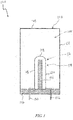
FIG. 1 is a side cross-sectional view illustrating a protection device according to the present disclosure. -
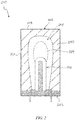
FIG. 2 is a side cross-sectional view illustrating a protection device according to the present disclosure. -
FIG. 3 is a side cross-sectional view illustrating a protection device according to the present disclosure. -
FIG. 4 is a side cross-sectional view illustrating a protection device according to the present disclosure. -
FIG. 5 is a side cross-sectional view illustrating a protection device according to the present disclosure. -
FIG. 6 is a side cross-sectional view illustrating a protection device according to the present disclosure. - The drawings are not necessarily to scale. The drawings are merely representations, not intended to portray specific parameters of the disclosure. The drawings are intended to depict the disclosure, and therefore should not be considered as limiting in scope. In the drawings, like numbering represents like elements.
- Furthermore, certain elements in some of the figures may be omitted, or illustrated not-to-scale, for illustrative clarity. Cross-sectional views may be in the form of "slices", or "near-sighted" cross-sectional views, omitting certain background lines otherwise visible in a "true" cross-sectional view, for illustrative clarity. Furthermore, for clarity, some reference numbers may be omitted in certain drawings.
- Fuse apparatuses and assemblies in accordance with the present disclosure will now be described more fully hereinafter with reference to the accompanying drawings, in which examples the system and method are shown. The fuse apparatuses and assemblies, however, may be embodied in many different forms and should not be construed as being limited to the embodiments set forth herein. Rather, these are provided so that this disclosure will be thorough and complete, and will fully convey the scope of the system and method to those skilled in the art.
- As mentioned above, EV fuses are a relatively new type of fuse to the automotive market within the last decade or so. Historically, these fuses have roots in industrial fuse design and have been slowly progressing to a more automotive-friendly design as volumes ramp up. The industrial design is typically very limiting in attachment into the application, overall fuse construction/appearance, and robustness. This disclosure provides a more automotive-friendly design, e.g., in shape/construction, performance, and features.
- Although the present disclosure may be applicable to fuses operating at a minimum of 500VDC and including, or even surpassing, 1000VDC. Current range may be even more broad, but typically includes ratings from 100A to 500A.
- The overall construction of the fuse element may take on an inverted u-shape. During an arc event, when there is an abrupt change in magnitude of current flow, the arc is forced outward and away from the two current paths of the u-shaped element due to electromagnetic forces (B-forces). Advantageously, by forcing the arc outward, the arc is lengthened and pushed away from metal of the fuse, which would otherwise feed the arc and, thus, more likely to be extinguished quickly.
- The disclosure also considers the fact that the closer together the current paths are, the higher this B-force is. As such, the disclosure herein may provide a barrier to separate the two paths the u-shaped element and provide insulation and additional arc suppression. Utilizing a highly endothermic material, e.g., melamine or Polyamide 46 (PA46), can also help extinguish the arc due to the close proximity and outgassing or endothermic effects. Utilizing this material in other areas of the fuse construction (e.g., entire body, etc.) may also help improve the arcing performance of the fuse, possibly allowing for the elimination of sand from high voltage fuses.
- An additional performance method for quenching the arc according to the present disclosure is to use a varied volume arc chamber. For example, as the arc consumes the current paths of the fuse element, the B-force forces the arc into a larger volume area, which reduces the energy of the arc not only by lengthening it, but by reducing the pressure. This is especially advantageous when designing a high voltage fuse without a filler material (e.g., sand).
- Furthermore, in the disclosure, splitter plates may be added to the device, wherein the arc can be cooled down by adding non-current-carrying mass to the arc path. Advantageously, this can improve the arcing performance with sand or potentially allow for elimination of the sand entirely. Still furthermore, packaging options may also be varied. For example, plug-in terminals can be utilized due to the construction of the bottom fuse section. Alternatively terminals can be formed and stamped with a hole for bolt-down applications. Further, the terminals can be formed along the sides of the fuse body to work with soldered PCB applications or clamp-type connections. Similar to OHEV / 10EV, this type of construction can accept custom terminals that can be soldered to terminal stubs.
- Still furthermore, another aspect of this disclosure is the addition of armor to enclose the fuse. Wrapping the high arc quenching material in a stronger material may allow more strength, thus keeping pressure inside of the fuse from escaping. This advantageously allows for a smaller footprint and reduces the use of arc-quenching material, which may be expensive.
- Referring to
FIG. 1 , an exemplary fuse apparatus/assembly/device (hereinafter, "device") 100 in accordance with the present disclosure is shown. Theexemplary device 100 may include ahousing 102 defining aninternal cavity 104. Although not limited to any particular shape or configuration, thehousing 102 may include abase wall 106, atop wall 108, and a set ofsidewalls 110. The various components of thehousing 102 may be made of an insulating material, such as an insulating plastic, e.g., nylon, glass-filled nylon, polyester and polycarbonate. Thebase wall 106, thetop wall 108, and thesidewalls 110 can be made of the same or different materials. - The
cavity 104 may include one or more circuit protection devices, e.g., fuses 114, disposed therein. Thefuse 114 may include afuse element 116 within thecavity 104, thefuse element 116 being formed from or comprised of any material having desirable electrically conductive properties. Thefuse element 116 can be nickel, copper, tin, or an alloy or mixture comprising nickel, copper, silver, gold, or tin, or any combination thereof. Thefuse element 116 may have an approximate thickness of between 5 and 20 mils (a mil being a thousandth of an inch). - The
fuse element 116 may include afirst component 118 and asecond component 120 separated by abarrier 122. Although non-limiting, the first andsecond components second components bridge 128. Thebridge 128 may include one or more weakened or thinned segments separated by perforations to form a set of fusible links. During an overcurrent event, the fusible links fail to prevent current from passing between the first andsecond components second components barrier 122. The first andsecond components barrier 122. Said another way, thefuse element 116 may wrap around thebarrier 122. - As further shown, a
first terminal 130 may be connected to thefirst component 118 and asecond terminal 132 may be connected to thesecond component 120. Here, the first andsecond terminals housing 102, through thebase wall 106. As illustrated, the free ends of the first andsecond terminals - The
cavity 104 may be filled with an arc suppressant material, such as silica, silicone, sand, or any combination thereof. An opening through thehousing 102 may allow thecavity 104 to be filled with the arc suppressant material. Although non-limiting, the hole may be centered in thetop wall 108 so that the arc suppressant material may evenly fill thecavity 104. - As shown, the
barrier 122 may extend between the first andsecond components fuse element 116. Thebarrier 122 and the first andsecond components base wall 106. In the present disclosure, thebarrier 122 may be constructed from a high outgassing or endothermic materials, such as stainless steel or aluminum. Thebarrier 122 and thebase wall 106 may be the same material. During use, thebarrier 122 is an arc barrier generally formed according to the shape of thefuse element 116. - Referring to
FIG. 2 , a fuse device (hereinafter, "device") 200 in accordance with the present disclosure is shown. Thedevice 200 may be the same or similar in certain aspects to thedevice 100 described above. As such, only certain aspects of thedevice 200 may hereinafter be described for the sake of brevity. Theexemplary device 200 may include ahousing 202 defining aninternal cavity 204. Au-shaped fuse element 216 may be disposed within thecavity 204. Thehousing 202 may include abase wall 206, atop wall 208, and a set ofside walls 210. - The
housing 202 may further include anarmor layer 240 extending into the cavity. Thearmor layer 240 may be formed along interior surfaces of thebase wall 206, thetop wall 208, and theside walls 210. In other embodiments, thearmor layer 240 may additionally, or alternatively, be formed along one or more exterior surfaces of thehousing 202. As shown, an interior surface 242 of thearmor layer 240 may define thecavity 204. Here thecavity 204 may take on an inverted teardrop shape or profile. The shape of thecavity 204 keeps anarc volume 244 generally equidistant from the interior surfaces of thehousing 202 to provide enhanced cooling and outgassing. Thearmor layer 240 may be a stainless steel. Thecavity 204 may be filled with an arc suppressant material, such as silica, or sand. - Referring to
FIG. 3 , a fuse device (hereinafter, "device") 300 in accordance with the present disclosure is shown. Thedevice 300 may be the same or similar in certain aspects to thedevices device 300 may hereinafter be described for the sake of brevity. Thedevice 300 may include ahousing 302 defining aninternal cavity 304. Au-shaped fuse element 316 may be disposed within thecavity 304. Thehousing 302 may include abase wall 306, atop wall 308, and a set ofside walls 310. - Extending into the
cavity 304 may be a plurality ofsplitter plates 348. Thesplitter plates 348 may generally extend perpendicular to thetop wall 308. During use, thesplitter plates 348 split arcs into a series of smaller arcs of less voltage. Thesplitter plates 348 may be symmetrical on both sides of a centerline extending through abarrier 322. Thesplitter plates 348 can be made of any ferrous material, including, but not limited to, steel. More or fewer plates than shown can be used in other implementations. Furthermore, it will be appreciated that the size ofsplitter plates 348, and the spacing(s) between them, can be chosen depending on the particular implementation, such as based on the overall size of thedevice 300 and/or the voltage or current that is expected to occur. - The
housing 302 may further include anarmor layer 340 formed along interior surfaces thereof. Furthermore, thecavity 304 may be filled with an arc suppressant material, such as silica, or sand. - Referring to
FIG. 4 , a fuse device (hereinafter, "device") 400 in accordance with the present disclosure is shown. Thedevice 400 may be the same or similar in certain aspects to thedevices device 400 may hereinafter be described for the sake of brevity. Theexemplary device 400 may include ahousing 402 defining aninternal cavity 404. Au-shaped fuse element 416 may be disposed within thecavity 404. Thehousing 402 may include abase wall 406, atop wall 408, and a set ofside walls 410. - The
housing 402 may further include anarmor layer 440 extending towards thefuse element 416. Thearmor layer 440 may be formed along interior surfaces of theside walls 410 and thebase wall 406. As shown, thearmor layer 440 is not formed along thetop wall 408. Aninterior surface 442 of thearmor layer 440 may partially define thecavity 404. Thearmor layer 440 may be a stainless steel. Thecavity 404 may be filled with an arc suppressant material, such as silica, or sand. - It will be appreciated that various housing and terminal configurations may be possible. For example, as shown in
device 500 ofFIG. 5 , afirst terminal 530 and asecond terminal 532 extend flat along abase wall 506 of ahousing 502. Each of the first andsecond terminals device 600 ofFIG. 6 , afirst terminal 630 and asecond terminal 632 extend along abase wall 606 and each sidewall 610 of ahousing 602. The first andsecond terminals - The foregoing discussion has been presented for purposes of illustration and description and is not intended to limit the disclosure to the form or forms disclosed herein. For example, various features of the disclosure may be grouped together in one or more aspects, embodiments, or configurations for the purpose of streamlining the disclosure. However, it should be understood that various features of the certain aspects, examples or configurations of the disclosure may be combined in alternate aspects, examples or configurations.
- As used herein, an element or step recited in the singular and proceeded with the word "a" or "an" should be understood as not excluding plural elements or steps, unless such exclusion is explicitly recited.
- The use of "including," "comprising," or "having" and variations thereof herein is meant to encompass the items listed thereafter and equivalents thereof as well as additional items. Accordingly, the terms "including," "comprising," or "having" and variations thereof are open-ended expressions and can be used interchangeably herein.
- The phrases "at least one", "one or more", and "and/or", as used herein, are open-ended expressions that are both conjunctive and disjunctive in operation. For example, each of the expressions "at least one of A, B and C", "at least one of A, B, or C", "one or more of A, B, and C", "one or more of A, B, or C" and "A, B, and/or C" means A alone, B alone, C alone, A and B together, A and C together, B and C together, or A, B and C together.
- All directional references (e.g., proximal, distal, upper, lower, upward, downward, left, right, lateral, longitudinal, front, back, top, bottom, above, below, vertical, horizontal, radial, axial, clockwise, and counterclockwise) are only used for identification purposes to aid the reader's understanding of the present disclosure, and do not create limitations, particularly as to the position, orientation, or use of this disclosure. Connection references (e.g., attached, coupled, connected, and joined) are to be construed broadly and may include intermediate members between a collection of elements and relative movement between elements unless otherwise indicated. As such, connection references do not necessarily infer that two elements are directly connected and in fixed relation to each other.
- Furthermore, identification references (e.g., primary, secondary, first, second, third, fourth, etc.) are not intended to connote importance or priority, but are used to distinguish one feature from another. The drawings are for purposes of illustration only and the dimensions, positions, order and relative sizes reflected in the drawings attached hereto may vary.
- Furthermore, the terms "substantial" or "substantially," as well as the terms "approximate" or "approximately," can be used interchangeably in some embodiments, and can be described using any relative measures acceptable by one of ordinary skill in the art. For example, these terms can serve as a comparison to a reference parameter, to indicate a deviation capable of providing the intended function. Although non-limiting, the deviation from the reference parameter can be, for example, in an amount of less than 1%, less than 3%, less than 5%, less than 10%, less than 15%, less than 20%, and so on.
- The present disclosure is not to be limited in scope by the specific examples described herein. Indeed, other various examples of and modifications to the present disclosure, in addition to those described herein, will be apparent to those of ordinary skill in the art from the foregoing description and accompanying drawings. Thus, such other examples and modifications are intended to fall within the scope of the present disclosure. Furthermore, the present disclosure has been described herein in the context of a particular implementation in a particular environment for a particular purpose. Those of ordinary skill in the art will recognize the usefulness is not limited thereto and the present disclosure may be beneficially implemented in any number of environments for any number of purposes. Thus, the claims set forth below are to be construed in view of the full breadth of the present disclosure as described herein.
Claims (15)
- A protection device, comprising:a housing defining a cavity; anda fuse element within the cavity, wherein the fuse element includes a first component and a second component separated by a barrier, and wherein the first and second components are joined at a bridge.
- The protection device of claim 1, further comprising a first terminal connected to the first component and a second terminal connected to the second component, wherein the first and second terminals extend outside of the housing.
- The protection device of claim 1 or 2, wherein the first and second components extend parallel to one another, and/or wherein the housing includes a base wall, wherein the barrier extends perpendicular to the base wall.
- The protection device of any of the claims 1-3, wherein the housing includes an armor layer formed along an exterior surface or an interior surface, preferably wherein the cavity has an inverted teardrop profile defined by an interior surface of the armor layer.
- The protection device of any of the preceding claims, further comprising a plurality of splitter plates extending into the cavity from the housing.
- The protection device of any of the preceding claims, further comprising an arc suppressant material within the cavity, and/or wherein the fuse element has an inverted U-shape.
- A fuse assembly, comprising:a housing defining a cavity; anda fuse element within the cavity, wherein the fuse element includes a first component extending parallel to a second component, wherein the first and second components are joined at a bridge, and wherein the first and second components are separated by a barrier.
- The fuse assembly of claim 7, further comprising a first terminal connected to the first component and a second terminal connected to the second component, wherein the first and second terminals extend outside of the housing.
- The fuse assembly of claim 7 or 8, wherein the housing includes a base wall, wherein the barrier and the first and second components extend perpendicular to the base wall.
- The fuse assembly of any of the claims 7-9, wherein the housing includes an armor layer extending into the cavity, and wherein the cavity preferably has an inverted teardrop profile defined by an interior surface of the armor layer.
- The fuse assembly of any of the claims 7-10, with one or more of the following:further comprising a plurality of splitter plates extending into the cavity from a top wall of the housing;further comprising an arc suppressant material within the cavity;wherein the fuse element has an inverted U-shape.
- A protection device, comprising:a housing defining a cavity; anda fuse element within the cavity, wherein the fuse element includes a first component and a second component separated by a barrier and joined at a fusible bridge, and wherein the fuse element has an inverted U-shape.
- The protection device of claim 12, further comprising a first terminal connected to the first component and a second terminal connected to the second component, wherein the first and second terminals extend through a base wall of the housing.
- The protection device of claim 12 or 13, wherein the housing includes an armor layer extending into the cavity, and wherein the cavity has an inverted teardrop profile defined by an interior surface of the armor layer.
- The protection device of any of the claims 12-14, further comprising a plurality of splitter plates extending into the cavity from a top wall of the housing.
Applications Claiming Priority (1)
| Application Number | Priority Date | Filing Date | Title |
|---|---|---|---|
| US16/838,521 US11049681B1 (en) | 2020-04-02 | 2020-04-02 | Protection device with u-shaped fuse element |
Publications (2)
| Publication Number | Publication Date |
|---|---|
| EP3889988A1 true EP3889988A1 (en) | 2021-10-06 |
| EP3889988B1 EP3889988B1 (en) | 2024-04-10 |
Family
ID=75339496
Family Applications (1)
| Application Number | Title | Priority Date | Filing Date |
|---|---|---|---|
| EP21166221.8A Active EP3889988B1 (en) | 2020-04-02 | 2021-03-31 | Protection device with u-shaped fuse element |
Country Status (4)
| Country | Link |
|---|---|
| US (1) | US11049681B1 (en) |
| EP (1) | EP3889988B1 (en) |
| JP (1) | JP2021163763A (en) |
| CN (1) | CN113496857A (en) |
Citations (3)
| Publication number | Priority date | Publication date | Assignee | Title |
|---|---|---|---|---|
| US2007313A (en) * | 1932-12-09 | 1935-07-09 | Corning Glass Works | Cartridge fuse |
| US4071837A (en) * | 1974-07-26 | 1978-01-31 | Bassani Ticino S.P.A. | Fuse cartridge |
| US5793275A (en) * | 1995-10-23 | 1998-08-11 | Iversen; Arthur H. | Exothermically assisted arc limiting fuses |
Family Cites Families (14)
| Publication number | Priority date | Publication date | Assignee | Title |
|---|---|---|---|---|
| US2734110A (en) * | 1956-02-07 | Magnetic blast fuses | ||
| JPS535150Y2 (en) * | 1973-06-22 | 1978-02-08 | ||
| IT1017466B (en) * | 1974-07-26 | 1977-07-20 | Bassani Spa | CARTRIDGE FUSE |
| JPS6017555U (en) * | 1984-06-04 | 1985-02-06 | 三菱電機株式会社 | Slit type current limiting fuse |
| US4612529A (en) * | 1985-03-25 | 1986-09-16 | Cooper Industries, Inc. | Subminiature fuse |
| EP0321771B1 (en) * | 1987-12-16 | 1992-06-10 | Wickmann-Werke GmbH | Miniature fuse |
| US4894633A (en) * | 1988-12-12 | 1990-01-16 | American Telephone And Telegraph Company | Fuse Apparatus |
| JPH0720828Y2 (en) * | 1989-06-14 | 1995-05-15 | エス・オー・シー株式会社 | Ultra-small current fuse |
| JP2624439B2 (en) * | 1993-04-30 | 1997-06-25 | コーア株式会社 | Circuit protection element |
| US6873243B1 (en) * | 2001-10-18 | 2005-03-29 | Cisco Technology, Inc. | Small-footprint fuse |
| US6927472B2 (en) * | 2001-11-14 | 2005-08-09 | International Business Machines Corporation | Fuse structure and method to form the same |
| DE102013213949A1 (en) * | 2013-07-16 | 2015-02-19 | Robert Bosch Gmbh | Fuse with separating element |
| CN206976273U (en) * | 2017-06-30 | 2018-02-06 | 厦门赛尔特电子有限公司 | A kind of HVDC thermal cut-off |
| JP6716516B2 (en) * | 2017-09-07 | 2020-07-01 | Littelfuseジャパン合同会社 | Protective element |
-
2020
- 2020-04-02 US US16/838,521 patent/US11049681B1/en active Active
-
2021
- 2021-03-31 EP EP21166221.8A patent/EP3889988B1/en active Active
- 2021-03-31 JP JP2021059054A patent/JP2021163763A/en active Pending
- 2021-04-02 CN CN202110361578.XA patent/CN113496857A/en active Pending
Patent Citations (3)
| Publication number | Priority date | Publication date | Assignee | Title |
|---|---|---|---|---|
| US2007313A (en) * | 1932-12-09 | 1935-07-09 | Corning Glass Works | Cartridge fuse |
| US4071837A (en) * | 1974-07-26 | 1978-01-31 | Bassani Ticino S.P.A. | Fuse cartridge |
| US5793275A (en) * | 1995-10-23 | 1998-08-11 | Iversen; Arthur H. | Exothermically assisted arc limiting fuses |
Also Published As
| Publication number | Publication date |
|---|---|
| JP2021163763A (en) | 2021-10-11 |
| US11049681B1 (en) | 2021-06-29 |
| EP3889988B1 (en) | 2024-04-10 |
| CN113496857A (en) | 2021-10-12 |
Similar Documents
| Publication | Publication Date | Title |
|---|---|---|
| EP2110831B1 (en) | Arc chute assembly for a circuit breaker | |
| EP3069363B1 (en) | Arc baffling device | |
| EP3275006B1 (en) | High voltage compact fuse assembly with magnetic arc deflection | |
| US11355300B2 (en) | Active/passive automotive fuse module | |
| EP4187572B1 (en) | Direct-current circuit breaker | |
| US20050263492A1 (en) | Molded arc chute | |
| US7586057B2 (en) | Electrical switching apparatus and vented case therefor | |
| WO2014116478A2 (en) | Arc runners suitable for dc molded case circuit breakers and related methods | |
| US9524842B2 (en) | Molded case circuit breakers with a switch PCB over an internal pocket and behind a front cover | |
| US11049681B1 (en) | Protection device with u-shaped fuse element | |
| CN216562920U (en) | Arc extinguish chamber of circuit breaker and circuit breaker | |
| EP2048678B1 (en) | Gassing insulator assembly, conductor assembly and electrical switching apparatus employing the same | |
| US4011425A (en) | Arc chute extension for increased interruption rating | |
| CA2983734C (en) | Circuit breakers with metal arc chutes with reduced electrical conductivity overlay material and related arc chutes | |
| CN116157973A (en) | switchboard | |
| US11631566B2 (en) | Modular high voltage fuse | |
| US6603384B1 (en) | Self-recovering current-limiting device having liquid metal | |
| US6917269B2 (en) | Low-voltage circuit breaker with an electric arc extinction system | |
| US11749483B1 (en) | Fuse with compartmentalized body and parallel fuse elements | |
| EP4195232B1 (en) | High voltage high current fuse with arc interrupter | |
| US7545247B2 (en) | Electrical switching apparatus, and case and terminal shield therefor | |
| JP7590379B2 (en) | fuse | |
| CN221573854U (en) | Hybrid fuse | |
| HK40087698A (en) | Direct-current circuit breaker | |
| HK40087698B (en) | Direct-current circuit breaker |
Legal Events
| Date | Code | Title | Description |
|---|---|---|---|
| PUAI | Public reference made under article 153(3) epc to a published international application that has entered the european phase |
Free format text: ORIGINAL CODE: 0009012 |
|
| STAA | Information on the status of an ep patent application or granted ep patent |
Free format text: STATUS: THE APPLICATION HAS BEEN PUBLISHED |
|
| AK | Designated contracting states |
Kind code of ref document: A1 Designated state(s): AL AT BE BG CH CY CZ DE DK EE ES FI FR GB GR HR HU IE IS IT LI LT LU LV MC MK MT NL NO PL PT RO RS SE SI SK SM TR |
|
| STAA | Information on the status of an ep patent application or granted ep patent |
Free format text: STATUS: REQUEST FOR EXAMINATION WAS MADE |
|
| 17P | Request for examination filed |
Effective date: 20220405 |
|
| RBV | Designated contracting states (corrected) |
Designated state(s): AL AT BE BG CH CY CZ DE DK EE ES FI FR GB GR HR HU IE IS IT LI LT LU LV MC MK MT NL NO PL PT RO RS SE SI SK SM TR |
|
| GRAP | Despatch of communication of intention to grant a patent |
Free format text: ORIGINAL CODE: EPIDOSNIGR1 |
|
| STAA | Information on the status of an ep patent application or granted ep patent |
Free format text: STATUS: GRANT OF PATENT IS INTENDED |
|
| INTG | Intention to grant announced |
Effective date: 20231116 |
|
| GRAS | Grant fee paid |
Free format text: ORIGINAL CODE: EPIDOSNIGR3 |
|
| GRAA | (expected) grant |
Free format text: ORIGINAL CODE: 0009210 |
|
| STAA | Information on the status of an ep patent application or granted ep patent |
Free format text: STATUS: THE PATENT HAS BEEN GRANTED |
|
| AK | Designated contracting states |
Kind code of ref document: B1 Designated state(s): AL AT BE BG CH CY CZ DE DK EE ES FI FR GB GR HR HU IE IS IT LI LT LU LV MC MK MT NL NO PL PT RO RS SE SI SK SM TR |
|
| REG | Reference to a national code |
Ref country code: GB Ref legal event code: FG4D |
|
| REG | Reference to a national code |
Ref country code: CH Ref legal event code: EP |
|
| REG | Reference to a national code |
Ref country code: DE Ref legal event code: R096 Ref document number: 602021011469 Country of ref document: DE |
|
| P01 | Opt-out of the competence of the unified patent court (upc) registered |
Effective date: 20240402 |
|
| REG | Reference to a national code |
Ref country code: IE Ref legal event code: FG4D |
|
| REG | Reference to a national code |
Ref country code: LT Ref legal event code: MG9D |
|
| REG | Reference to a national code |
Ref country code: NL Ref legal event code: MP Effective date: 20240410 |
|
| REG | Reference to a national code |
Ref country code: AT Ref legal event code: MK05 Ref document number: 1675807 Country of ref document: AT Kind code of ref document: T Effective date: 20240410 |
|
| PG25 | Lapsed in a contracting state [announced via postgrant information from national office to epo] |
Ref country code: NL Free format text: LAPSE BECAUSE OF FAILURE TO SUBMIT A TRANSLATION OF THE DESCRIPTION OR TO PAY THE FEE WITHIN THE PRESCRIBED TIME-LIMIT Effective date: 20240410 |
|
| PG25 | Lapsed in a contracting state [announced via postgrant information from national office to epo] |
Ref country code: NL Free format text: LAPSE BECAUSE OF FAILURE TO SUBMIT A TRANSLATION OF THE DESCRIPTION OR TO PAY THE FEE WITHIN THE PRESCRIBED TIME-LIMIT Effective date: 20240410 |
|
| PG25 | Lapsed in a contracting state [announced via postgrant information from national office to epo] |
Ref country code: IS Free format text: LAPSE BECAUSE OF FAILURE TO SUBMIT A TRANSLATION OF THE DESCRIPTION OR TO PAY THE FEE WITHIN THE PRESCRIBED TIME-LIMIT Effective date: 20240810 |
|
| PG25 | Lapsed in a contracting state [announced via postgrant information from national office to epo] |
Ref country code: BG Free format text: LAPSE BECAUSE OF FAILURE TO SUBMIT A TRANSLATION OF THE DESCRIPTION OR TO PAY THE FEE WITHIN THE PRESCRIBED TIME-LIMIT Effective date: 20240410 |
|
| PG25 | Lapsed in a contracting state [announced via postgrant information from national office to epo] |
Ref country code: HR Free format text: LAPSE BECAUSE OF FAILURE TO SUBMIT A TRANSLATION OF THE DESCRIPTION OR TO PAY THE FEE WITHIN THE PRESCRIBED TIME-LIMIT Effective date: 20240410 Ref country code: FI Free format text: LAPSE BECAUSE OF FAILURE TO SUBMIT A TRANSLATION OF THE DESCRIPTION OR TO PAY THE FEE WITHIN THE PRESCRIBED TIME-LIMIT Effective date: 20240410 |
|
| PG25 | Lapsed in a contracting state [announced via postgrant information from national office to epo] |
Ref country code: GR Free format text: LAPSE BECAUSE OF FAILURE TO SUBMIT A TRANSLATION OF THE DESCRIPTION OR TO PAY THE FEE WITHIN THE PRESCRIBED TIME-LIMIT Effective date: 20240711 |
|
| PG25 | Lapsed in a contracting state [announced via postgrant information from national office to epo] |
Ref country code: PT Free format text: LAPSE BECAUSE OF FAILURE TO SUBMIT A TRANSLATION OF THE DESCRIPTION OR TO PAY THE FEE WITHIN THE PRESCRIBED TIME-LIMIT Effective date: 20240812 |
|
| PG25 | Lapsed in a contracting state [announced via postgrant information from national office to epo] |
Ref country code: ES Free format text: LAPSE BECAUSE OF FAILURE TO SUBMIT A TRANSLATION OF THE DESCRIPTION OR TO PAY THE FEE WITHIN THE PRESCRIBED TIME-LIMIT Effective date: 20240410 |
|
| PG25 | Lapsed in a contracting state [announced via postgrant information from national office to epo] |
Ref country code: AT Free format text: LAPSE BECAUSE OF FAILURE TO SUBMIT A TRANSLATION OF THE DESCRIPTION OR TO PAY THE FEE WITHIN THE PRESCRIBED TIME-LIMIT Effective date: 20240410 |
|
| PG25 | Lapsed in a contracting state [announced via postgrant information from national office to epo] |
Ref country code: PL Free format text: LAPSE BECAUSE OF FAILURE TO SUBMIT A TRANSLATION OF THE DESCRIPTION OR TO PAY THE FEE WITHIN THE PRESCRIBED TIME-LIMIT Effective date: 20240410 |
|
| PG25 | Lapsed in a contracting state [announced via postgrant information from national office to epo] |
Ref country code: LV Free format text: LAPSE BECAUSE OF FAILURE TO SUBMIT A TRANSLATION OF THE DESCRIPTION OR TO PAY THE FEE WITHIN THE PRESCRIBED TIME-LIMIT Effective date: 20240410 |
|
| PG25 | Lapsed in a contracting state [announced via postgrant information from national office to epo] |
Ref country code: PT Free format text: LAPSE BECAUSE OF FAILURE TO SUBMIT A TRANSLATION OF THE DESCRIPTION OR TO PAY THE FEE WITHIN THE PRESCRIBED TIME-LIMIT Effective date: 20240812 Ref country code: PL Free format text: LAPSE BECAUSE OF FAILURE TO SUBMIT A TRANSLATION OF THE DESCRIPTION OR TO PAY THE FEE WITHIN THE PRESCRIBED TIME-LIMIT Effective date: 20240410 Ref country code: NO Free format text: LAPSE BECAUSE OF FAILURE TO SUBMIT A TRANSLATION OF THE DESCRIPTION OR TO PAY THE FEE WITHIN THE PRESCRIBED TIME-LIMIT Effective date: 20240710 Ref country code: LV Free format text: LAPSE BECAUSE OF FAILURE TO SUBMIT A TRANSLATION OF THE DESCRIPTION OR TO PAY THE FEE WITHIN THE PRESCRIBED TIME-LIMIT Effective date: 20240410 Ref country code: IS Free format text: LAPSE BECAUSE OF FAILURE TO SUBMIT A TRANSLATION OF THE DESCRIPTION OR TO PAY THE FEE WITHIN THE PRESCRIBED TIME-LIMIT Effective date: 20240810 Ref country code: HR Free format text: LAPSE BECAUSE OF FAILURE TO SUBMIT A TRANSLATION OF THE DESCRIPTION OR TO PAY THE FEE WITHIN THE PRESCRIBED TIME-LIMIT Effective date: 20240410 Ref country code: GR Free format text: LAPSE BECAUSE OF FAILURE TO SUBMIT A TRANSLATION OF THE DESCRIPTION OR TO PAY THE FEE WITHIN THE PRESCRIBED TIME-LIMIT Effective date: 20240711 Ref country code: FI Free format text: LAPSE BECAUSE OF FAILURE TO SUBMIT A TRANSLATION OF THE DESCRIPTION OR TO PAY THE FEE WITHIN THE PRESCRIBED TIME-LIMIT Effective date: 20240410 Ref country code: ES Free format text: LAPSE BECAUSE OF FAILURE TO SUBMIT A TRANSLATION OF THE DESCRIPTION OR TO PAY THE FEE WITHIN THE PRESCRIBED TIME-LIMIT Effective date: 20240410 Ref country code: BG Free format text: LAPSE BECAUSE OF FAILURE TO SUBMIT A TRANSLATION OF THE DESCRIPTION OR TO PAY THE FEE WITHIN THE PRESCRIBED TIME-LIMIT Effective date: 20240410 Ref country code: AT Free format text: LAPSE BECAUSE OF FAILURE TO SUBMIT A TRANSLATION OF THE DESCRIPTION OR TO PAY THE FEE WITHIN THE PRESCRIBED TIME-LIMIT Effective date: 20240410 Ref country code: RS Free format text: LAPSE BECAUSE OF FAILURE TO SUBMIT A TRANSLATION OF THE DESCRIPTION OR TO PAY THE FEE WITHIN THE PRESCRIBED TIME-LIMIT Effective date: 20240710 |
|
| REG | Reference to a national code |
Ref country code: DE Ref legal event code: R097 Ref document number: 602021011469 Country of ref document: DE |
|
| PG25 | Lapsed in a contracting state [announced via postgrant information from national office to epo] |
Ref country code: DK Free format text: LAPSE BECAUSE OF FAILURE TO SUBMIT A TRANSLATION OF THE DESCRIPTION OR TO PAY THE FEE WITHIN THE PRESCRIBED TIME-LIMIT Effective date: 20240410 |
|
| PG25 | Lapsed in a contracting state [announced via postgrant information from national office to epo] |
Ref country code: EE Free format text: LAPSE BECAUSE OF FAILURE TO SUBMIT A TRANSLATION OF THE DESCRIPTION OR TO PAY THE FEE WITHIN THE PRESCRIBED TIME-LIMIT Effective date: 20240410 |
|
| PG25 | Lapsed in a contracting state [announced via postgrant information from national office to epo] |
Ref country code: CZ Free format text: LAPSE BECAUSE OF FAILURE TO SUBMIT A TRANSLATION OF THE DESCRIPTION OR TO PAY THE FEE WITHIN THE PRESCRIBED TIME-LIMIT Effective date: 20240410 |
|
| PG25 | Lapsed in a contracting state [announced via postgrant information from national office to epo] |
Ref country code: SK Free format text: LAPSE BECAUSE OF FAILURE TO SUBMIT A TRANSLATION OF THE DESCRIPTION OR TO PAY THE FEE WITHIN THE PRESCRIBED TIME-LIMIT Effective date: 20240410 Ref country code: RO Free format text: LAPSE BECAUSE OF FAILURE TO SUBMIT A TRANSLATION OF THE DESCRIPTION OR TO PAY THE FEE WITHIN THE PRESCRIBED TIME-LIMIT Effective date: 20240410 |
|
| PG25 | Lapsed in a contracting state [announced via postgrant information from national office to epo] |
Ref country code: SM Free format text: LAPSE BECAUSE OF FAILURE TO SUBMIT A TRANSLATION OF THE DESCRIPTION OR TO PAY THE FEE WITHIN THE PRESCRIBED TIME-LIMIT Effective date: 20240410 |
|
| PG25 | Lapsed in a contracting state [announced via postgrant information from national office to epo] |
Ref country code: SM Free format text: LAPSE BECAUSE OF FAILURE TO SUBMIT A TRANSLATION OF THE DESCRIPTION OR TO PAY THE FEE WITHIN THE PRESCRIBED TIME-LIMIT Effective date: 20240410 Ref country code: SK Free format text: LAPSE BECAUSE OF FAILURE TO SUBMIT A TRANSLATION OF THE DESCRIPTION OR TO PAY THE FEE WITHIN THE PRESCRIBED TIME-LIMIT Effective date: 20240410 Ref country code: RO Free format text: LAPSE BECAUSE OF FAILURE TO SUBMIT A TRANSLATION OF THE DESCRIPTION OR TO PAY THE FEE WITHIN THE PRESCRIBED TIME-LIMIT Effective date: 20240410 Ref country code: EE Free format text: LAPSE BECAUSE OF FAILURE TO SUBMIT A TRANSLATION OF THE DESCRIPTION OR TO PAY THE FEE WITHIN THE PRESCRIBED TIME-LIMIT Effective date: 20240410 Ref country code: DK Free format text: LAPSE BECAUSE OF FAILURE TO SUBMIT A TRANSLATION OF THE DESCRIPTION OR TO PAY THE FEE WITHIN THE PRESCRIBED TIME-LIMIT Effective date: 20240410 Ref country code: CZ Free format text: LAPSE BECAUSE OF FAILURE TO SUBMIT A TRANSLATION OF THE DESCRIPTION OR TO PAY THE FEE WITHIN THE PRESCRIBED TIME-LIMIT Effective date: 20240410 |
|
| PLBE | No opposition filed within time limit |
Free format text: ORIGINAL CODE: 0009261 |
|
| STAA | Information on the status of an ep patent application or granted ep patent |
Free format text: STATUS: NO OPPOSITION FILED WITHIN TIME LIMIT |
|
| 26N | No opposition filed |
Effective date: 20250113 |
|
| PG25 | Lapsed in a contracting state [announced via postgrant information from national office to epo] |
Ref country code: SI Free format text: LAPSE BECAUSE OF FAILURE TO SUBMIT A TRANSLATION OF THE DESCRIPTION OR TO PAY THE FEE WITHIN THE PRESCRIBED TIME-LIMIT Effective date: 20240410 |
|
| PG25 | Lapsed in a contracting state [announced via postgrant information from national office to epo] |
Ref country code: SE Free format text: LAPSE BECAUSE OF FAILURE TO SUBMIT A TRANSLATION OF THE DESCRIPTION OR TO PAY THE FEE WITHIN THE PRESCRIBED TIME-LIMIT Effective date: 20240410 |
|
| PG25 | Lapsed in a contracting state [announced via postgrant information from national office to epo] |
Ref country code: MC Free format text: LAPSE BECAUSE OF FAILURE TO SUBMIT A TRANSLATION OF THE DESCRIPTION OR TO PAY THE FEE WITHIN THE PRESCRIBED TIME-LIMIT Effective date: 20240410 |
|
| REG | Reference to a national code |
Ref country code: CH Ref legal event code: H13 Free format text: ST27 STATUS EVENT CODE: U-0-0-H10-H13 (AS PROVIDED BY THE NATIONAL OFFICE) Effective date: 20251023 |
|
| PG25 | Lapsed in a contracting state [announced via postgrant information from national office to epo] |
Ref country code: LU Free format text: LAPSE BECAUSE OF NON-PAYMENT OF DUE FEES Effective date: 20250331 |
|
| GBPC | Gb: european patent ceased through non-payment of renewal fee |
Effective date: 20250331 |
|
| REG | Reference to a national code |
Ref country code: BE Ref legal event code: MM Effective date: 20250331 |
|
| PG25 | Lapsed in a contracting state [announced via postgrant information from national office to epo] |
Ref country code: GB Free format text: LAPSE BECAUSE OF NON-PAYMENT OF DUE FEES Effective date: 20250331 |
|
| PG25 | Lapsed in a contracting state [announced via postgrant information from national office to epo] |
Ref country code: BE Free format text: LAPSE BECAUSE OF NON-PAYMENT OF DUE FEES Effective date: 20250331 |
|
| PG25 | Lapsed in a contracting state [announced via postgrant information from national office to epo] |
Ref country code: CH Free format text: LAPSE BECAUSE OF NON-PAYMENT OF DUE FEES Effective date: 20250331 |
|
| PG25 | Lapsed in a contracting state [announced via postgrant information from national office to epo] |
Ref country code: IE Free format text: LAPSE BECAUSE OF NON-PAYMENT OF DUE FEES Effective date: 20250331 |
|
| PGFP | Annual fee paid to national office [announced via postgrant information from national office to epo] |
Ref country code: DE Payment date: 20260102 Year of fee payment: 6 |
|
| PGFP | Annual fee paid to national office [announced via postgrant information from national office to epo] |
Ref country code: IT Payment date: 20260220 Year of fee payment: 6 |
|
| PGFP | Annual fee paid to national office [announced via postgrant information from national office to epo] |
Ref country code: FR Payment date: 20260209 Year of fee payment: 6 |