EP3889983B1 - Abnehmbarer knopf zum betätigen einer schaltanlage und schaltanlagenvorrichtung mit dem abnehmbaren knopf - Google Patents
Abnehmbarer knopf zum betätigen einer schaltanlage und schaltanlagenvorrichtung mit dem abnehmbaren knopf Download PDFInfo
- Publication number
- EP3889983B1 EP3889983B1 EP20382263.0A EP20382263A EP3889983B1 EP 3889983 B1 EP3889983 B1 EP 3889983B1 EP 20382263 A EP20382263 A EP 20382263A EP 3889983 B1 EP3889983 B1 EP 3889983B1
- Authority
- EP
- European Patent Office
- Prior art keywords
- plunger
- knob
- housing
- detachable
- anchoring means
- Prior art date
- Legal status (The legal status is an assumption and is not a legal conclusion. Google has not performed a legal analysis and makes no representation as to the accuracy of the status listed.)
- Active
Links
Images


Classifications
-
- H—ELECTRICITY
- H01—ELECTRIC ELEMENTS
- H01H—ELECTRIC SWITCHES; RELAYS; SELECTORS; EMERGENCY PROTECTIVE DEVICES
- H01H19/00—Switches operated by an operating part which is rotatable about a longitudinal axis thereof and which is acted upon directly by a solid body external to the switch, e.g. by a hand
- H01H19/02—Details
- H01H19/10—Movable parts; Contacts mounted thereon
- H01H19/14—Operating parts, e.g. turn knob
-
- H—ELECTRICITY
- H01—ELECTRIC ELEMENTS
- H01H—ELECTRIC SWITCHES; RELAYS; SELECTORS; EMERGENCY PROTECTIVE DEVICES
- H01H71/00—Details of the protective switches or relays covered by groups H01H73/00 - H01H83/00
- H01H71/10—Operating or release mechanisms
- H01H71/50—Manual reset mechanisms which may be also used for manual release
- H01H71/56—Manual reset mechanisms which may be also used for manual release actuated by rotatable knob or wheel
-
- G—PHYSICS
- G05—CONTROLLING; REGULATING
- G05G—CONTROL DEVICES OR SYSTEMS INSOFAR AS CHARACTERISED BY MECHANICAL FEATURES ONLY
- G05G1/00—Controlling members, e.g. knobs or handles; Assemblies or arrangements thereof; Indicating position of controlling members
- G05G1/08—Controlling members for hand actuation by rotary movement, e.g. hand wheels
- G05G1/10—Details, e.g. of discs, knobs, wheels or handles
- G05G1/12—Means for securing the members on rotatable spindles or the like
-
- H—ELECTRICITY
- H01—ELECTRIC ELEMENTS
- H01H—ELECTRIC SWITCHES; RELAYS; SELECTORS; EMERGENCY PROTECTIVE DEVICES
- H01H3/00—Mechanisms for operating contacts
- H01H3/32—Driving mechanisms, i.e. for transmitting driving force to the contacts
- H01H3/42—Driving mechanisms, i.e. for transmitting driving force to the contacts using cam or eccentric
-
- H—ELECTRICITY
- H01—ELECTRIC ELEMENTS
- H01H—ELECTRIC SWITCHES; RELAYS; SELECTORS; EMERGENCY PROTECTIVE DEVICES
- H01H71/00—Details of the protective switches or relays covered by groups H01H73/00 - H01H83/00
- H01H71/10—Operating or release mechanisms
- H01H71/1009—Interconnected mechanisms
- H01H71/1018—Interconnected mechanisms with only external interconnections
-
- H—ELECTRICITY
- H01—ELECTRIC ELEMENTS
- H01H—ELECTRIC SWITCHES; RELAYS; SELECTORS; EMERGENCY PROTECTIVE DEVICES
- H01H9/00—Details of switching devices, not covered by groups H01H1/00 - H01H7/00
- H01H9/20—Interlocking, locking, or latching mechanisms
- H01H9/28—Interlocking, locking, or latching mechanisms for locking switch parts by a key or equivalent removable member
- H01H9/281—Interlocking, locking, or latching mechanisms for locking switch parts by a key or equivalent removable member making use of a padlock
-
- H—ELECTRICITY
- H02—GENERATION; CONVERSION OR DISTRIBUTION OF ELECTRIC POWER
- H02B—BOARDS, SUBSTATIONS OR SWITCHING ARRANGEMENTS FOR THE SUPPLY OR DISTRIBUTION OF ELECTRIC POWER
- H02B13/00—Arrangement of switchgear in which switches are enclosed in, or structurally associated with, a casing, e.g. cubicle
-
- G—PHYSICS
- G05—CONTROLLING; REGULATING
- G05G—CONTROL DEVICES OR SYSTEMS INSOFAR AS CHARACTERISED BY MECHANICAL FEATURES ONLY
- G05G5/00—Means for preventing, limiting or returning the movements of parts of a control mechanism, e.g. locking controlling member
- G05G5/28—Means for preventing, limiting or returning the movements of parts of a control mechanism, e.g. locking controlling member for preventing unauthorised access to the controlling member or its movement to a command position
Definitions
- the present invention refers in general to knobs or handles for manually actuating switchgear like: fused switches, circuit breakers, changeover switches, actuating mechanism for switches, and switching devices in general.
- an object of the invention is to provide a detachable knob that can be easily and quickly detached and attached repeatedly from a switchgear.
- An additional object of the invention is to provide a knob of the above type that can be manufactured in a cost-effective manner, without using screws or other similar ancillary components
- Another object of the invention is to provide a switchgear device integrating security features that prevent accidental or undesired operations of the associated switching devices, specially to the switching on state, as to guarantee safety of operators.
- This object involves the use of the above-mentioned detachable knob with a switchgear device.
- circuit breakers are installed within a distribution board closet, and the handle for switching on and off the circuit breaker body, is assembled outside the closet with the door of the closet, such that a long transmission rod is mechanically connected the handle with the circuit breaker.
- distribution boards are a multi-pole installations that includes several breaking poles, for example assembled as an array of circuit breakers and mounted on a common shaft that operate all the circuit breakers simultaneously.
- These multi-pole switching assemblies generally comprises a mechanism for operating the cut-off poles which is coupled to a common shaft arranged to pass through the cut-off poles, this cut-off shaft being coupled to the various movable contacts of these poles.
- This actuator mechanism is manually operated by a handle or knob coupled to a transmission rod, such that by rotating the handle by actuation of the control device, this kinematic chain makes it possible to move all movable contacts of the cut-off poles from their closed position to their cut-off position (and vice versa) and thus to control an abrupt engagement or tripping. of the switching device.
- handles for switchgear are disclosed for example in patent publications: US-10.312.046 B1 , and US-2017/0242453 A1 .
- the handle operating the switches can be removed to ensure that the switch remains in the open position.
- the handle remains attached to the switch but it is locked in the open position, to impede undesired switching-on of the switch until maintenance works are completed and the switch is unlocked.
- Topology of alternating current electrical systems with distributed neutral vary depending on the function of the neutral line in the electrical system.
- the purpose of the neutral line is two-folded, first the neutral line or pole is used for the return current of the circuit, and secondly as a safety measure in electrical installations to protect users from accidental electrical discharges.
- Distributed low voltage neutral is mainly used to provide a single-phase voltage to supply circuits, such as lighting or control auxiliaries, in addition to the three-phase voltage.
- the neutral conductor is used to supply single-phase loads, thus, cutting off (opening) the neutral pole upstream must be carried out after switching off the main poles or phase lines, or at least simultaneously with that of the switching-off of the main poles or lines. In this way, it is assured that the neutral pole is always connected when the main poles are connected or about to be connected.
- the neutral pole can no longer serve as its mains purpose that is to allow the current to return to the source, and a 230 V supply of the single-phase loads.
- This accidental switching-off of the neutral might have catastrophic consequences on the receivers or loads.
- the return current instead of returning through the neutral line, might return through the rest of the receiver impedances connected to the rest of the phase lines of the three-phase system, causing network imbalances and over voltages in the receivers and causing damages.
- the most widely used protection system is the earth or ground connection system.
- Transformer secondary neutral can be connected to ground (directly or by impedance) or isolated from ground.
- the earths of the installation which are always connected to the earth of the building in which they are installed, either directly with the distributed earth cable or by means of the neutral conductor.
- PEN This single conductor is called PEN and has the dual function of: A) of neutral where it is used as a current return for single-phase loads and also B) as a protective earth conductor.
- the neutral function is limited to the neutral being fixed. However, it may be necessary that this common conductor for neutral and ground has to be disconnected consciously and temporarily for testing and maintenance tasks of the ground protection systems.
- the PEN conductor is associated, either globally or in sections, with a plate-type contact that is manually unscrewed and screwed independently of the general switch or the associated section switch that is operated to electrically isolate the section for checking purposes.
- fuses and circuit breakers are usually used as protection devices to isolate them from voltage for manipulation.
- Some equipment on the market integrate in a single product the fuse, switch, and module for fixed dis-connectable neutral.
- German patent application DE 4206378 A1 refers to an actuator for switch devices having a rotating handle form-fitted to the switch shaft of the device in the rotary direction, and snap-fitted on to the shaft in the axial direction.
- the handle has a pivot lever. In the closed position, this blocks movements of the handle and also prevents pulling of the switch shaft.
- switchgear should be understood to encompass: actuators for switches, fused switches, circuit breakers, changeover switches, and switching devices in general.
- the detachable knob of the invention comprises a knob housing configured to be manually grabbed and rotated about a rotation axis "X", and anchoring means placed inside the knob housing and configured to transit from an engaged position to a disengaged position and vice versa.
- the anchoring means are capable of attaching the knob, the knob housing in particular, with a part of a switchgear, such that the knob can be operatively attached to the switchgear to operate the same.
- the anchoring means detach the knob (the knob housing) from that part of a switchgear, and the knob can be detached from the switchgear.
- the detachable knob further comprises a plunger arranged inside the housing and axially displaceable along the rotation axis "X".
- the plunger is configured to actuate on the anchoring means, to bring the anchoring means from their engaged position to their disengaged position and vice versa.
- the plunger is axially displaceable relative to the anchoring means between two stable (permanent) axial positions at axis "X", namely: a pushed-down position in which the plunger remains stable and force the anchoring means to their engaged or to their disengaged position, and a release position in which the anchoring means remains stable and bring the anchoring means to their other position.
- the detachable knob additionally includes biasing means arranged inside the knob housing to axially bias the plunger away from the anchoring means.
- the knob housing is open at the bottom and has an opening at a top part thereof, through which the plunger is accessible to allow an user to manually push-down the plunger along axis "X", in a way that by pushing down the plunger, it transits reversely between its two stable positions. Therefore, the knob operates as a bi-stable mechanism, which in one of its stable configurations it can engage a part of a switchgear, and in the other stable configuration, it disengages from the switch gear.
- the bi-stable operation of the knob is carried out by retention means formed with the plunger and the knob housing.
- the anchoring means might be formed in the knob housing or in the plunger, such that the knob housing and the plunger cooperates to engage or disengage the anchoring means.
- the knob includes a crown member that is co-axially assembled with the plunger along the rotation axis "X" and inside the knob housing, and the anchoring means are integrally formed in the crown member.
- the plunger is arranged closer to a top area of the knob housing, and the crown member is closer to a bottom open base of the knob housing.
- the crown is attached to the knob housing such that the crown and the knob housing are jointly rotatable, that is, they do not move axially or rotate relative to each other.
- the anchoring means are embodied as two or more flexible claws (preferably four claws, distributed in two pairs of claws facing each other) integrally formed with the crown, and axially projecting from the crown main body.
- the claws are configured to flex in a direction intersecting with the axis "X", such that, the anchoring means are in their engaged position when the claws are flexed due to the contact with the plunger, and in the disengaged position when the claws are not in contact with the plunger, so the claws are in their rest or relaxed position.
- the knob housing has a cylindrical chamber extending along the rotation axis "X”, and the plunger is a cylindrical tubular body and it is received within that cylindrical chamber.
- the plunger has an open bottom base, such that in the pushed-down position, the crown is received inside the plunger in a way that the plunger forces the claws to flex towards their engaged position. In the released position of the plunger, the claws are in their rest position.
- the external surface of the plunger and the internal surface of cylindrical chamber are facing each other, and the knob housing has at least one groove (first groove) formed on the internal surface of the cylindrical chamber, and the plunger has at least one groove (second groove) formed on its external surface.
- the knob further comprising a ball (a bearing ball) received within both grooves, such that the ball can roll along the first and second grooves as the plunger moves up and down the axis "X".
- the first groove at the knob housing lies on a plane orthogonal to the axis "X", so this groove is an arc of a circumference or a whole circumference, thereby, the ball can only move horizontally inside the groove of the knob on a plane orthogonal de the axis "X".
- the second groove has the form of a closed loop, having a first valley and a second valley placed above the first valley, and an ascending path and a descending path, both paths communicating the first and second valleys.
- First and second valleys are vertically aligned along an axis parallel to rotation axis "X". Each valley is configured to retain the ball inside the valley, so the first valley retains the plunger in a first axial permanent position against the force exerted by the biasing means, and the second valley retains the plunger in a second axial permanent position against the force exerted by the biasing means.
- the biasing means is a compression spring, co-axially arranged about axis "X", between the plunger and the anchoring means, such that the displacement of the plunger towards its engaged position is against the force exerted by the biasing means, and the displacement of the plunger towards its disengaged position is assisted by the force of the biasing means.
- the knob housing has a lateral level projecting in an orthogonal direction with respect to axis "X", having an internal cavity providing access to the plunger.
- the knob further comprises a displaceable latch received within the cavity, and displaceable inside the cavity between a locked position and a unlocked position.
- the latch is configured to lock the plunger in its locked position, as to impede the plunger displacement.
- Second biasing means are assembled biasing the latch away from the plunger.
- a switchgear module comprising a housing having an aperture providing access to the housing interior, and a cover or lid removably mounted with the housing closing the aperture.
- the module further comprises a disconnectable switch member enclosed inside the housing, and a switch actuation mechanism also enclosed, at least in part, inside the housing.
- a detachable knob preferably the detachable knob previously described, is detachably coupled with the module.
- the detachable knob is arranged above the cover and it is mechanically connected with the switch actuation mechanism through the cover, in a way that the knob impedes removal of the cover when the knob is coupled with the module, thus, the cover can be removed and the housing interior accessed, only when the detachable knob is detached from the module. Therefore, for disconnecting the switch member can only be disconnected, after detaching the knob and removing the cover, and since the knob is not coupled with the actuation mechanism, this cannot be operated, thereby implementing a security feature for the module.
- the knob When the detachable knob is coupled with an actuation mechanism, the knob is reversely rotatable between a switched-on position (in which the switches operated by the knob are switched-on), and a switched-off position in which the switches are off.
- the detachable knob is configured to be detachable in its switched-off position, and to unable detachment in its switched-on position.
- the disconnectable switch member is a metal plate, for example screwed to an internal support within the housing.
- the cover has an opening and a neck extending around the neck, and wherein the anchoring means are configured to engage with the neck in their engaged position, and wherein the detachable knob is coupled with the switch mechanism through that opening.
- the module has a rotatable shaft received with the opening, wherein the shaft is coupled with the switch mechanism, and wherein the crown is configured to coupled and uncouple with the shaft.
- the switch array of the invention accomplishes the following advantages and features:
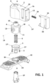
- Figure 1 shows a preferred implementation of the detachable knob (1) of the invention, that comprises a knob housing (2) configured to be manually rotated about a rotation axis "X", and anchoring means (3) placed inside the knob housing (2) and configured to transit between an engaged position and a disengaged position and vice versa.
- a plunger (4) is arranged inside the knob housing (2) and it is axially displaceable along the rotation axis "X".
- the plunger (4) is configured to bring the anchoring means (3) from their engaged position to their disengaged position and vice versa, as it will be described in detail later-on.
- the detachable knob (1) comprises a crown (5) co-axially mounted with the plunger (4) along the rotation axis "X" and placed inside the knob housing (2).
- the crown (5) is attached to the knob housing (2) in a way that the crown (5) and the knob housing (2) are jointly rotatable.
- the crown (5) has two lateral arms (17,17') extending orthogonally to the axis "X", that are received inside axially extending grooves (18,18') formed in the plunger (4).
- the anchoring means (3) are two or more flexible claws (7) integrally formed with the crown (5), so that the claws (7) can flex in a direction that intersect the axis "X".
- the detachable knob (1) comprises a biasing means, that in this implementation consist of a compression spring (6), co-axially arranged about axis "X", and placed inside the knob housing (2) to axially bias the plunger (4) away from the crown (5).
- a biasing means that in this implementation consist of a compression spring (6), co-axially arranged about axis "X", and placed inside the knob housing (2) to axially bias the plunger (4) away from the crown (5).
- the knob housing (2) has a cylindrical chamber (8) formed around the rotation axis "X”, and the plunger (4) has a cylindrical configuration and it is received inside that cylindrical chamber (8).
- the knob housing (2) has an open bottom base (see Figure 2A ), and an opening (9) at a top part thereof, in a way that the plunger (4) is accessible through that opening (9), whereas the anchoring means (3) are accessible through the open bottom base (8).
- the plunger (4) has a cylindrical neck (10) at a top part thereof, which is received inside the top opening (9) as shown for example in Figures 5A, 5B , in a way that the cylindrical neck (10) serves as a push-bottom to actuate the knob (1).
- the plunger (4) it is placed above the crown (5), and it is axially displaceable relative to the crown (5) and relative to the anchoring means (3) between two stable axial positions at axis "X", namely: a pushed-down position ( Figures 5B, 5C ) in which the plunger (4) remains stable and forces the anchoring means (3) to their engaged position, and a release position ( Figure 5A ) in which the plunger (4) remains stable and in which the anchoring means (3) are in their disengaged position. Since the plunger (4) is accessible from outside the knob housing (2), the plunger (4) can be pushed-down along axis "X", such that by pushing down the plunger (4), it transits reversely between its two stable positions.
- the plunger (4) has an open bottom base (11), and the plunger (4) and the crown (5) are configured such that in the pushed-down position of the plunger ( Figure 5B ), the crown (5) is received inside the plunger (4), and the plunger (4) forces the claws (7) to flex towards their engaged position.
- the anchoring means (3) that is, the claws (7) engage with a neck (23) of a cover (22) of a switch gear as it will be explained later-on.
- the external surface of the plunger (4) and the internal surface of cylindrical chamber (8) are facing each other, and the knob housing (2) has at least one first groove (12) provided on the internal surface of the cylindrical chamber (8).
- the plunger (4) has at least one second groove (13) provided on its external surface, and a ball (14) is received within the first and second grooves (12,13), such that the ball (14) can roll along the first and second grooves (12,13) upon displacement of the plunger (4).
- Each of the first grooves (12,12') has the form of arch of circumference and lies on a plane orthogonal to the axis "X", such that axial displacement of the balls (14,14') is prevented.
- the knob housing (2) has a lateral level (2a) that projects in an orthogonal direction with respect to axis "X".
- the lateral level (2a) has an internal cavity (15) providing access to the chamber (8) and to the plunger (4).
- the knob (1) further comprises a displaceable latch (16) received within the cavity (15), such that the latch (16) is displaceable between a locked position in which it impedes plunger (4) displacement, and an unlocked position in which plunger (4) displacement is allowed.
- a compression spring (24) is placed between the knob housing (2a) and the latch (16), biasing the latch (16) away from the knob housing.
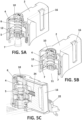
- FIG. 3 A - 3C shows the crown (5) in more detail.
- the crown (5) has a cylindrical base (19), two lateral arms (18,18') projecting diametrically from the base (19), and four flexible claws (7) extending from the base (19), wherein each claw (7) has a U-shaped configuration, and are adapted to flex towards the axis of the base (19).
- the base (19) has a cylindrical opening (20) at its top base to receive the spring (6), and a squared protrusion (21) placed internally right below the opening (20).
- Figures 4 A - 4C shows the plunger (4) in more detail, and specially the configuration of the grooves (13,13').
- FIGs 5A - 5C The complete assembly is represented in Figures 5A - 5C , in particular the two stable axial positions of the plunger (4).
- the plunger (4) is in its released position in which the plunger (4) remains stable in its upper axial position, and in which the claws (7) are disengaged, so that the detachable knob (1) can be detached from a switch gear.
- the plunger (4) does not press the claws (7) of the crown, thus, the claws (7) are expanded.
- the plunger (4) is in its engaged position in which the plunger (4) remains stable in its lower-most position, and in which the claws (7) are flexed towards the crown (5) axis, so that the detachable knob (1) can be attached to a part of a switch gear. It can be noted in Figure 5B , that in this position the plunger (4) presses the claws (7), such that the claws are flexed towards the crown (5) interior.
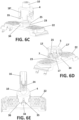
- Figure 6A shows more in detail how the crown (5) is coupled with the cover (22).
- the claws (7) are adapted to engage with neck (23) of the cover (22), and by means of a lib (25) that it formed around the edge of the neck (23).
- a lib 25) that it formed around the edge of the neck (23).
- a shaft (27) is received inside the neck (23) co-axially with the axis "X", and it is coupled with the crown (5).
- the top end of the shaft (27) has a squared cavity (28) inside which the squared protrusion (21) of the crown (5) is coupled, so that, the rotation of the knob housing (2) is transmitted to the shaft (27) through the crown (5) when the detachable knob (1) is engaged with a switch-gear.
- the cover (22) has a wall (34) near the neck (23), and that the plunger (4) has a notch (35) shaped complementary to the wall, in a way that the wall (34) can be received in the notch (36) as shown for example in Figure 6E .
- the plunger (4) can be pushed-down only when the notch (35) and the wall (34) are aligned vertically as shown in Figure 6E , otherwise, the wall (34) would contact with the bottom edge (36) of the plunger (4), and downwards displacement of the plunger (4) is blocked by the wall (34).
- the detachable knob (1) can only be actuated in a predefined angular position, for example when the knob (1) is in its Off position when it is attached to a switching device, so that in its On position, the knob (1) cannot be detached from the switching device.
- the knob (1) has to be oriented in the insertion position (in any other position it would not fit with the shaft (27) due to an existing "poka yoke" between crown (25) and the shaft (27), and then it slightly pressed against the neck (23) until the crown gets anchored to the lib (25) of the neck (23) by bending its four claws (7).
- the drive shaft (27) is coupled directly with the crown (5).
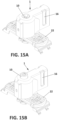
- the crown (5) has internally, four battlements (35a,35b,35c,35d) configured to be received inside four corresponding recesses (36a,36b,36c,26d) ( Figure 15D ) formed at the upper part of the shaft (27) around squared cavity (28), so that, together they transmit the torque exerted by the user to the mechanism.
- the assembly is secured by closing the claws by the action of the plunger (4) while it moves downwards pushed by a user, forcing the claws to close and engaging the neck (23). Only once the knob is engaged with the neck, the knob can it be turned, moving it to other positions.
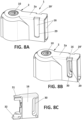
- FIG 8A - 8C , 9A - 9C illustrate the assembly of the knob housing (2) with the lateral latch (16) in different relative positions between the two components.
- the latch (16) is meant to lock the movement of the plunger (5), and as consequence of that, the rotation of the knob (1), for example when the knob (1) is attached to a switching device (not shown) in its open position, and some maintenance works has to be carried out in an electric installation.
- the latch (16) is displaceable inside the internal cavity (15) of the lateral level (2a), between a locked position ( Figure 8B ) in which it impedes plunger (4) displacement, and an unlocked position ( Figure 8A ) in which plunger (4) displacement is allowed.
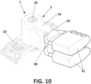
- the lateral level (2a) has to lateral windows (29,29'), and the latch (16) has a passing-through passage (30), which are arranged such that in the locked position ( Figure 8B ), the lateral windows (29,29') and passage (30) overlap, and one or two padlocks (31) can be installed locking the latch (16) with the knob housing (2) ( Figure 10 ) to impede latch movement.
- the windows (29,29') are closed by the latch (16) as shown in Figure 8A .
- the upper extension (31) prevents the latch from being inserted to its locked position, in order to avoid safety failures (otherwise the operator could place the padlock and think that the system is safe, when in fact the knob could be removed).
- the plunger (16) can only be moved to locked position and the knob locked, when the detachable knob (1) is in its Off position shown in Figure 10 .
- padlocks (31) are installed as shown in Figure 10 , the plunger (4) cannot be pressed-down (and consequently, the detachable knob cannot be detached), and the detachable knob (1) cannot be rotated (thus, a switching device to which the knob is coupled, cannot be turned On, being locked in the Off position).
- FIG 11 illustrates how the bi-stable pulsation mechanism operates.
- the bi-stable operation is achieved by at least one ball (14) and at least one groove (13) formed on the external surface of the plunger (4) (and on an internal surface of the knob housing).
- Each of the second grooves (13,13') has the form of a closed loop, having a bottom valley (V1) and a top valley (V2) placed above the bottom valley (V1) (they are vertically aligned), and an ascending path (13a) and a descending path (13b), both paths communicating the bottom and top valleys (V1,V2).
- the two valleys (V1,V2) are configured to retain the ball (14) inside each valley such that the ball (14) retains the plunger (4) in an axial permanent position against the force exerted by the compression spring (6).
- each groove (13) has two high points (T1, T2) both located at the same high and above the top valley (V2).
- Each to the two valleys and the two high points, has the form of an elbow as to retain temporally the ball as shown in the sequence of Figure 11 .
- the ascending path (13b) communicates the bottom valley (V1) with a first high point (T2), and the descending path (13a) communicates the other high point (T1) with the bottom valley (V1).
- the ascending path (13b) has two branches, an inclined branch that departs from the bottom valley (V1), and a vertical branch the extends from the inclined branch to the high point (T2).
- the descending path (13a) has two branches, an inclined branch that departs from the bottom valley (V1), and a vertical branch the extends from the inclined branch to the other high point (T1).
- An intermediate path (13c) communicates the two high points (T1 ,T2) with the top valley (V2), and it has two branches that are inclined with respect to each other, one branch communicates the top valley (V1) with the high point (T2), and the other branch communicates the top valley (V1) with the other high point (T1).
- the horizontal line represents the first groove (12) formed internally in the knob housing (2), and as it can be appreciated, the ball only moves horizontally within the groove (12).
- the valleys, paths, corners of the groove (13) are designed, such that the ball can only travel according to the route described above, but not in opposite direction.
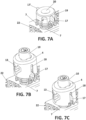
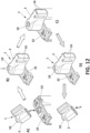
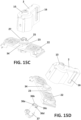
- the switchgear module (37) represented in Figures 13A-13C , that comprises the detachable knob (1) previously described and a switching device (38).
- the switching device (38) has a housing (39) having an aperture (40) providing access to the housing (39) interior, and a cover (22) removably mounted with the housing (39) closing the aperture (40).
- the detachable knob (1) is arranged above the cover (22) and it is detachably connected with the switch actuation mechanism (42) through the cover (22) and by means of the drive shaft (27), such that the knob (1) impede removal of the cover (22) when the knob (1) is coupled with the module (37). Therefore, the cover (22) can be removed and the housing interior accessed only when the detachable knob (1) is detached from the actuation mechanism (42), for example, in order to remove the disconnectable switch member (41).
- the detachable knob (1) is reversibly rotatable between a switched-On position (when the switching device (38) is switched-On) and a switched-Off position (when the switching device (38) is switched-Off) to operate the switch actuation mechanism, and detachable knob is configured to be detachable in the switched-Off position and to impede detachment in its switched-On position.
- the detachable knob (1) can be rotated about axis "X", up to 290° ( ⁇ 145° from the coupling position (0°) free of restrictions. This means that it can be used to operate switch actuation mechanisms with 2, 3, 4... or as many positions as desired, located in a range of 290°, without having to maintain a minimum angle between them.
- the rotation angle is limited by the switch actuation mechanism to which the knob (1) is attached. That is, if for example the end position of the switch actuation mechanism are at 90°, the rotation of the knob (1) is restricted to those 90°.
- the coupling position (marked with 0° angle in Figure 16A ) can be located wherever the switch actuation mechanism requires, that is, it is not necessary that it is in the horizontal, vertical,...etc. but it adapts to each particular switch actuation mechanism. From this coupling position, the knob can be turned a maximum of 145° clockwise and anti-clockwise as shown in Figure 16A .
- FIG. 17 An example of that feature of the knob (1) is shown in Figure 17 , when the knob is meant to operate a multi-pole switching device.
- the coupling position is horizontal, 0°, and the switching mechanism to operate has three positions, TEST (-30°) ( Figure 17A ), OFF (0°) ( Figure 17B ), and ON (90°) ( Figure 17C ), with stable positions at -30° and 90°. Therefore, in this example the knob (1) can rotate 120° (-30° / +90°).
- the knob can be detached, whereas in any other position, the plunger cannot be pushed-down and the knob cannot be removed.
- the detachable knob with all its components has been designed such that its assembly during its manufacturing process, is very simple in order to shorten assembly time. For this reason, all assembly can be carried out by means of clip joints so that the process is completely manual, that is, it does not require tools, which also has a positive impact on manufacturing cost.
- knob housing (2) is positioned upside down ( Figure 2A ), and the plunger (4) is housed inside.
Landscapes
- Engineering & Computer Science (AREA)
- Physics & Mathematics (AREA)
- General Physics & Mathematics (AREA)
- Automation & Control Theory (AREA)
- Power Engineering (AREA)
- Switch Cases, Indication, And Locking (AREA)
Claims (14)
- Abnehmbarer Knopf (1) umfassend:ein Knopfgehäuse (2), das so konfiguriert ist, dass es manuell um eine Drehachse (X) gedreht werden kann,Verankerungsmittel (3), die innerhalb des Knopfgehäuses (2) angeordnet sind und so konfiguriert sind, dass sie sich umkehrbar zwischen einer einrastenden und einer ausgerasteten Position bewegen können,dadurch gekennzeichnet, dass der abnehmbare Knopf (1) weiter umfasst:einen innerhalb des Knopfgehäuses (2) angeordneten und axial entlang der Drehachse (X) verschiebbaren Stößel (4), wobei der Stößel (4) so ausgebildet ist, dass er die Verankerungsmittel (3) aus ihrer Eingriffsstellung in ihre gelöste Position und umgekehrt bringen kann,Spannmittel, die innerhalb des Knopfgehäuses (2) angeordnet sind, um den Stößel (4) axial von den Verankerungsmitteln (3) wegzuspannen,wobei der Stößel (4) gegenüber den Verankerungsmitteln (3) zwischen zwei stabilen axialen Positionen an der Achse (X) axial verschiebbar ist,eine erste stabile heruntergedrückte Position, in der der Stößel (4) stabil verbleibt und die Verankerungsmittel (3) in ihre eingerastete oder in ihre gelöste Position zwingt, und eine zweite stabile gelöste Position, in der der Stößel (4) stabil verbleibt und in der sich die Verankerungsmittel (3) in der anderen Position der jeweiligen Einrast- oder gelösten Position befinden undwobei der Stößel (4) von außerhalb des Knopfgehäuses (2) zugänglich ist, um zu ermöglichen, dass der Stößel (4) entlang der Achse (X) nach unten gedrückt betätigt werden kann,derart, dass durch Herunterdrücken des Stößels (4) der Stößel (4) rückwärts zwischen der ersten stabilen heruntergedrückten Position und der zweiten stabilen gelösten Position hin- und herwechselt.
- Abnehmbarer Knopf (1) nach Anspruch 1, eine Krone (5), die mit dem Stößel (4) entlang der Drehachse (X) innerhalb des Knopfgehäuses (2) koaxial montiert ist und wobei eine Krone (5) an dem Knopfgehäuse (2) so befestigt ist, dass die Krone (5) und das Knopfgehäuse (2) gemeinsam drehbar sind, und wobei die Verankerungsmittel (3) zwei oder mehr flexible Krallen (7) sind, die integral mit der Krone (5) ausgebildet sind, wobei sich die flexiblen Klauen (7) in einer Richtung biegen können, die die Achse (X) schneidet.
- Abnehmbarer Knopf (1) nach Anspruch 1 oder 2, wobei das Knopfgehäuse (2) eine zylindrische Kammer (8) aufweist, die sich entlang der Drehachse (X) erstreckt, und wobei der Stößel (4) eine zylindrische Konfiguration aufweist und er innerhalb dieser zylindrischen Kammer (8) aufgenommen ist, und wobei das Knopfgehäuse (2) eine offene untere Basis (11) und eine Öffnung (9) an einem oberen Teil davon aufweist, und wobei der Stößel (4) durch die Öffnung (9) zugänglich ist und die Verankerungsmittel (3) durch die offene untere Basis (11) zugänglich sind.
- Abnehmbarer Knopf (1) nach Anspruch 2, wobei der Stößel (4) eine offene Bodenbasis aufweist und wobei der Stößel (4) und die Krone (5) derart ausgebildet sind, dass in der ersten stabilen heruntergedrückten Position des Stößels (4) die Krone (5) innerhalb des Stößels (4) aufgenommen wird und der Stößel (4) die flexiblen Klauen (7) zwingt, sich in Richtung ihrer Eingriffsstellung zu biegen.
- Abnehmbarer Knopf (1) nach einem der vorhergehenden Ansprüche, wobei eine Außenfläche des Stößels und die Innenfläche einer zylindrischen Kammer (8) einander zugewandt sind, wobei das Knopfgehäuse (2) mindestens eine erste Nut (12) aufweist, die auf der Innenfläche der zylindrischen Kammer (8) vorgesehen ist, und wobei der Stößel (4) mindestens eine zweite Nut (13) aufweist, auf seiner Außenfläche vorgesehen ist und der Knopf (1) eine Kugel (14) aufweist, die innerhalb der ersten und zweiten Nut (12, 13) aufgenommen ist, so dass die Kugel (14) bei Verschiebung des Stößels (4) entlang der ersten und zweiten Nut rollen kann, und wobei die erste Nut (12) auf einer Ebene liegt, die orthogonal zur Achse (X) ist, so dass eine axiale Verschiebung der Kugel (14) verhindert wird und wobei die zweite Nut (13) die Form einer geschlossenen Schleife hat.
- Abnehmbarer Knopf (1) nach Anspruch 5, wobei die zweite Nut (13) eine erste Vertiefung (V1) und eine zweite Vertiefung (V2) angeordnet oberhalb der ersten Vertiefung (V1) aufweist, und einen aufsteigenden Weg (13a) und einen absteigenden Weg (13b), wobei beide Wege mit den ersten und zweiten Vertiefungen in Kontakt treten, und wobei die Vertiefungen (V1,V2) so angeordnet sind, dass sie die Kugel (14) innerhalb der jeweiligen Vertiefung halten, so dass die Kugel (14) den Stößel (4) in einer axialen permanenten Position gegen die durch das Spannmittel ausgeübte Kraft zurückhalten.
- Abnehmbarer Knopf (1) nach einem der vorhergehenden Ansprüche, wobei der Stößel (4) gegenüber den Verankerungsmitteln (3) zwischen zwei stabilen axialen Positionen entlang der Achse (X) axial verschiebbar ist, wobei der Stößel (4) stabil bleibt und die Verankerungsmittel (3) in ihre eingerastete oder in ihre gelöste Position zwingen, und eine zweite stabile gelöste Position, in der die Verankerungsmittel (3) stabil bleiben und die Verankerungsmittel (3) in ihre andere Position bringen.
- Abnehmbarer Knopf nach einem der Ansprüche 2 bis 7, wobei das Spannmittel eine um die Achse (X) koaxial angeordnete Druckfeder (6) zwischen dem Stößel (4) und der Krone (5) ist.
- Abnehmbarer Knopf (1) nach einem der vorhergehenden Ansprüche, wobei das Knopfgehäuse (2) eine seitliche Ebene (2a) aufweist, die einen inneren Hohlraum (15) aufweist der den Zugang zum Stößel (4) ermöglicht, und wobei das Knopfgehäuse (2) weiter einen innerhalb des Hohlraums (15) aufgenommenen verschiebbaren Riegel (16) umfasst, und wobei der verschiebbare Riegel (16) zwischen einer verriegelten Position, in der der Riegel (16) die Verschiebung des Stößels (4) verhindert und einer nicht verriegelten Position, in der die Verschiebung des Stößels (4) ermöglicht wird verschoben werden kann.
- Schaltgerätemodul (37), umfassend: ein Modulgehäuse (39) mit einer Öffnung (40), die Zugang zum Inneren des Modulgehäuses ermöglicht, einer mit dem Modulgehäuse (39) abnehmbar montierten Abdeckung (22), die die Öffnung (40) verschließt, ein abschaltbares Schaltelement (41), das im Inneren des Modulgehäuses (39) eingeschlossen ist, einen Schaltbetätigungsmechanismus (42), der zumindest teilweise im Inneren des Modulgehäuses (39) eingeschlossen ist, einen abnehmbaren Knopf (1), der über der Abdeckung (22) angeordnet und durch die Abdeckung (22) lösbar mit dem Schalterbetätigungsmechanismus (42) verbunden ist, so dass der Knopf (1) das Entfernen der Abdeckung (22) verhindert, wenn der Knopf (1) mit dem Modul (37) gekoppelt ist, und die Abdeckung (22) entfernt werden kann und auf das Gehäuseinnere zugegriffen werden kann, wenn der abnehmbare Knopf (1) von dem Schalterbetätigungsmechanismus (42) gelöst ist, Verankerungsmittel, die innerhalb des Knopfgehäuses platziert und so konfiguriert sind, dass sie umkehrbar von einer einrastenden Position aus bewegt werden, in der sie in der Lage sind, den Knopf mit einem Teil einer Schaltanlage zu verbinden, zu einer gelösten Stellung, in der die Verankerungseinrichtungen den Knopf von dem Teil einer Schaltanlage lösen dadurch gekennzeichnet, dass der abnehmbare Knopf (1) der abnehmbare Knopf (1) wie in einem der Ansprüche 1 bis 9 definiert ist.
- Modul nach Anspruch 10, wobei der abnehmbare Knopf (1) reversibel zwischen einer eingeschalteten Stellung und einer ausgeschalteten Stellung drehbar ist, um den Schalterbetätigungsmechanismus (42) zu betätigen, und wobei der abnehmbare Knopf (1) so ausgebildet ist, dass er in der ausgeschalteten Stellung lösbar ist und das Lösen in seiner eingeschalteten Stellung verhindert.
- Modul nach Anspruch 10 oder 11, wobei das abschaltbare Schaltelement (41) eine Metallplatte ist.
- Modul nach Anspruch 10, wobei der Deckel (22) eine Öffnung (26) und einen Hals (23) aufweist, der sich um die Öffnung (26) erstreckt, und wobei die Verankerungsmittel so konfiguriert sind, dass sie mit dem Hals (23) in ihrer Eingriffsposition in Eingriff treten, und wobei der abnehmbare Knopf (1) mit dem Schaltmechanismus durch diese Öffnung (26) gekoppelt ist.
- Modul nach einem der Ansprüche 10 bis 13, ferner umfassend eine drehbare Welle (27), die mit der Öffnung (26) aufgenommen ist, wobei die Welle (27) mit dem Schaltmechanismus gekoppelt ist und wobei eine Krone (5) so konfiguriert ist, dass sie mit der Welle (27) koppeln und entkoppeln kann.
Priority Applications (3)
| Application Number | Priority Date | Filing Date | Title |
|---|---|---|---|
| ES20382263T ES2988908T3 (es) | 2020-04-01 | 2020-04-01 | Pomo desmontable para accionar aparamenta y un dispositivo de aparamenta que incorpora el pomo desmontable |
| EP20382263.0A EP3889983B1 (de) | 2020-04-01 | 2020-04-01 | Abnehmbarer knopf zum betätigen einer schaltanlage und schaltanlagenvorrichtung mit dem abnehmbaren knopf |
| US17/203,603 US11664179B2 (en) | 2020-04-01 | 2021-03-16 | Detachable knob for actuating switchgear, and a switchgear device incorporating the detachable knob |
Applications Claiming Priority (1)
| Application Number | Priority Date | Filing Date | Title |
|---|---|---|---|
| EP20382263.0A EP3889983B1 (de) | 2020-04-01 | 2020-04-01 | Abnehmbarer knopf zum betätigen einer schaltanlage und schaltanlagenvorrichtung mit dem abnehmbaren knopf |
Publications (3)
| Publication Number | Publication Date |
|---|---|
| EP3889983A1 EP3889983A1 (de) | 2021-10-06 |
| EP3889983C0 EP3889983C0 (de) | 2024-04-03 |
| EP3889983B1 true EP3889983B1 (de) | 2024-04-03 |
Family
ID=70189886
Family Applications (1)
| Application Number | Title | Priority Date | Filing Date |
|---|---|---|---|
| EP20382263.0A Active EP3889983B1 (de) | 2020-04-01 | 2020-04-01 | Abnehmbarer knopf zum betätigen einer schaltanlage und schaltanlagenvorrichtung mit dem abnehmbaren knopf |
Country Status (3)
| Country | Link |
|---|---|
| US (1) | US11664179B2 (de) |
| EP (1) | EP3889983B1 (de) |
| ES (1) | ES2988908T3 (de) |
Families Citing this family (2)
| Publication number | Priority date | Publication date | Assignee | Title |
|---|---|---|---|---|
| USD1014443S1 (en) * | 2021-05-04 | 2024-02-13 | Schneider Electric Industries Sas | Part of a circuit breaker |
| US11984709B2 (en) * | 2021-12-01 | 2024-05-14 | Appleton Grp Llc | Actuator for a switch gear of an electric panel |
Family Cites Families (7)
| Publication number | Priority date | Publication date | Assignee | Title |
|---|---|---|---|---|
| DE9202697U1 (de) * | 1992-02-29 | 1993-07-01 | Klöckner-Moeller GmbH, 53115 Bonn | Betätigungsvorrichtung für Schaltgeräte |
| US5634357A (en) * | 1995-03-03 | 1997-06-03 | Federal-Hoffman, Inc. | Enclosure handle |
| ITTO20130455A1 (it) * | 2013-06-04 | 2014-12-05 | Menber S Spa | Interruttore, in particolare interruttore staccabatterie per veicoli e simili |
| FR3048119B1 (fr) | 2016-02-19 | 2018-03-30 | Schneider Electric Industries Sas | Systeme de commande rotative pour un appareil |
| US10403454B2 (en) * | 2016-06-27 | 2019-09-03 | Abb Schweiz Ag | Circuit breaker system and safety operating handle for a circuit breaker system |
| FR3054925B1 (fr) * | 2016-08-02 | 2020-05-15 | Socomec | Module de commande pour appareil de coupure electrique modulaire et appareil de coupure electrique modulaire obtenu |
| US10312046B1 (en) | 2018-01-19 | 2019-06-04 | Eaton Intelligent Power Limited | Rotary motion switching apparatus usable with circuit interrupter |
-
2020
- 2020-04-01 EP EP20382263.0A patent/EP3889983B1/de active Active
- 2020-04-01 ES ES20382263T patent/ES2988908T3/es active Active
-
2021
- 2021-03-16 US US17/203,603 patent/US11664179B2/en active Active
Also Published As
| Publication number | Publication date |
|---|---|
| EP3889983C0 (de) | 2024-04-03 |
| EP3889983A1 (de) | 2021-10-06 |
| US11664179B2 (en) | 2023-05-30 |
| ES2988908T3 (es) | 2024-11-22 |
| US20210313126A1 (en) | 2021-10-07 |
Similar Documents
| Publication | Publication Date | Title |
|---|---|---|
| US7462792B1 (en) | Power transmission safety system | |
| EP1583121B1 (de) | Modulare Trennschalter | |
| EP1583120B1 (de) | Drehschalter für elektrische Schaltschränke mit Trennschalter. | |
| US11664179B2 (en) | Detachable knob for actuating switchgear, and a switchgear device incorporating the detachable knob | |
| US20170032906A1 (en) | Disconnect operating handles suitable for circuit breakers and related bucket assemblies and handle interlocks | |
| US9875868B2 (en) | Locking device for high-voltage switchgear | |
| CZ2002390A3 (cs) | Vícepólové bezpečnostní spínací zařízení | |
| EP2430322B1 (de) | Arretiervorrichtung für drehbewegungsbeschränkung | |
| CA3079901A1 (en) | Locking device for circuit breaker operation device | |
| US10141129B2 (en) | Interlock apparatus of ring main unit | |
| KR200481214Y1 (ko) | 가스절연개폐장치의 조작기구 잠금장치 | |
| US11616347B2 (en) | Cam selector for an earthing switch | |
| US6989498B1 (en) | Method and device for locking | |
| US5521344A (en) | Circuit breaker lock-out block | |
| KR102213037B1 (ko) | 전동기 제어반 | |
| AT512813A1 (de) | Vorrichtung für einen Trennschalter | |
| US7064286B2 (en) | Secure operation mechanism for electrical shutdown device and device equipped with such a mechanism | |
| CN107465111A (zh) | 配电板 | |
| EP3828908B1 (de) | Modulare drehschalteranordnung | |
| KR200481378Y1 (ko) | 가스절연개폐장치의 가동축 잠금장치 | |
| US12243704B2 (en) | Rotary lockout tagout latch system | |
| CN115831635B (zh) | 柜外操作手柄及电控柜 | |
| KR20260050121A (ko) | 소형 차단기용 원방 조작 장치 | |
| US20240234054A1 (en) | Device for disconnecting an electrical circuit | |
| CN109585197B (zh) | 一种开关电器操作装置 |
Legal Events
| Date | Code | Title | Description |
|---|---|---|---|
| PUAI | Public reference made under article 153(3) epc to a published international application that has entered the european phase |
Free format text: ORIGINAL CODE: 0009012 |
|
| STAA | Information on the status of an ep patent application or granted ep patent |
Free format text: STATUS: THE APPLICATION HAS BEEN PUBLISHED |
|
| AK | Designated contracting states |
Kind code of ref document: A1 Designated state(s): AL AT BE BG CH CY CZ DE DK EE ES FI FR GB GR HR HU IE IS IT LI LT LU LV MC MK MT NL NO PL PT RO RS SE SI SK SM TR |
|
| STAA | Information on the status of an ep patent application or granted ep patent |
Free format text: STATUS: REQUEST FOR EXAMINATION WAS MADE |
|
| 17P | Request for examination filed |
Effective date: 20220329 |
|
| RBV | Designated contracting states (corrected) |
Designated state(s): AL AT BE BG CH CY CZ DE DK EE ES FI FR GB GR HR HU IE IS IT LI LT LU LV MC MK MT NL NO PL PT RO RS SE SI SK SM TR |
|
| GRAP | Despatch of communication of intention to grant a patent |
Free format text: ORIGINAL CODE: EPIDOSNIGR1 |
|
| STAA | Information on the status of an ep patent application or granted ep patent |
Free format text: STATUS: GRANT OF PATENT IS INTENDED |
|
| INTG | Intention to grant announced |
Effective date: 20231218 |
|
| GRAS | Grant fee paid |
Free format text: ORIGINAL CODE: EPIDOSNIGR3 |
|
| GRAA | (expected) grant |
Free format text: ORIGINAL CODE: 0009210 |
|
| STAA | Information on the status of an ep patent application or granted ep patent |
Free format text: STATUS: THE PATENT HAS BEEN GRANTED |
|
| AK | Designated contracting states |
Kind code of ref document: B1 Designated state(s): AL AT BE BG CH CY CZ DE DK EE ES FI FR GB GR HR HU IE IS IT LI LT LU LV MC MK MT NL NO PL PT RO RS SE SI SK SM TR |
|
| REG | Reference to a national code |
Ref country code: CH Ref legal event code: EP |
|
| REG | Reference to a national code |
Ref country code: IE Ref legal event code: FG4D |
|
| REG | Reference to a national code |
Ref country code: DE Ref legal event code: R096 Ref document number: 602020028268 Country of ref document: DE |
|
| U01 | Request for unitary effect filed |
Effective date: 20240425 |
|
| U07 | Unitary effect registered |
Designated state(s): AT BE BG DE DK EE FI FR IT LT LU LV MT NL PT SE SI Effective date: 20240506 |
|
| PG25 | Lapsed in a contracting state [announced via postgrant information from national office to epo] |
Ref country code: IS Free format text: LAPSE BECAUSE OF FAILURE TO SUBMIT A TRANSLATION OF THE DESCRIPTION OR TO PAY THE FEE WITHIN THE PRESCRIBED TIME-LIMIT Effective date: 20240803 |
|
| PG25 | Lapsed in a contracting state [announced via postgrant information from national office to epo] |
Ref country code: HR Free format text: LAPSE BECAUSE OF FAILURE TO SUBMIT A TRANSLATION OF THE DESCRIPTION OR TO PAY THE FEE WITHIN THE PRESCRIBED TIME-LIMIT Effective date: 20240403 |
|
| PG25 | Lapsed in a contracting state [announced via postgrant information from national office to epo] |
Ref country code: GR Free format text: LAPSE BECAUSE OF FAILURE TO SUBMIT A TRANSLATION OF THE DESCRIPTION OR TO PAY THE FEE WITHIN THE PRESCRIBED TIME-LIMIT Effective date: 20240704 |
|
| PG25 | Lapsed in a contracting state [announced via postgrant information from national office to epo] |
Ref country code: CZ Free format text: LAPSE BECAUSE OF FAILURE TO SUBMIT A TRANSLATION OF THE DESCRIPTION OR TO PAY THE FEE WITHIN THE PRESCRIBED TIME-LIMIT Effective date: 20240403 |
|
| PG25 | Lapsed in a contracting state [announced via postgrant information from national office to epo] |
Ref country code: PL Free format text: LAPSE BECAUSE OF FAILURE TO SUBMIT A TRANSLATION OF THE DESCRIPTION OR TO PAY THE FEE WITHIN THE PRESCRIBED TIME-LIMIT Effective date: 20240403 |
|
| PG25 | Lapsed in a contracting state [announced via postgrant information from national office to epo] |
Ref country code: PL Free format text: LAPSE BECAUSE OF FAILURE TO SUBMIT A TRANSLATION OF THE DESCRIPTION OR TO PAY THE FEE WITHIN THE PRESCRIBED TIME-LIMIT Effective date: 20240403 Ref country code: NO Free format text: LAPSE BECAUSE OF FAILURE TO SUBMIT A TRANSLATION OF THE DESCRIPTION OR TO PAY THE FEE WITHIN THE PRESCRIBED TIME-LIMIT Effective date: 20240703 Ref country code: IS Free format text: LAPSE BECAUSE OF FAILURE TO SUBMIT A TRANSLATION OF THE DESCRIPTION OR TO PAY THE FEE WITHIN THE PRESCRIBED TIME-LIMIT Effective date: 20240803 Ref country code: HR Free format text: LAPSE BECAUSE OF FAILURE TO SUBMIT A TRANSLATION OF THE DESCRIPTION OR TO PAY THE FEE WITHIN THE PRESCRIBED TIME-LIMIT Effective date: 20240403 Ref country code: GR Free format text: LAPSE BECAUSE OF FAILURE TO SUBMIT A TRANSLATION OF THE DESCRIPTION OR TO PAY THE FEE WITHIN THE PRESCRIBED TIME-LIMIT Effective date: 20240704 Ref country code: CZ Free format text: LAPSE BECAUSE OF FAILURE TO SUBMIT A TRANSLATION OF THE DESCRIPTION OR TO PAY THE FEE WITHIN THE PRESCRIBED TIME-LIMIT Effective date: 20240403 Ref country code: RS Free format text: LAPSE BECAUSE OF FAILURE TO SUBMIT A TRANSLATION OF THE DESCRIPTION OR TO PAY THE FEE WITHIN THE PRESCRIBED TIME-LIMIT Effective date: 20240703 |
|
| REG | Reference to a national code |
Ref country code: ES Ref legal event code: FG2A Ref document number: 2988908 Country of ref document: ES Kind code of ref document: T3 Effective date: 20241122 |
|
| REG | Reference to a national code |
Ref country code: DE Ref legal event code: R097 Ref document number: 602020028268 Country of ref document: DE |
|
| PG25 | Lapsed in a contracting state [announced via postgrant information from national office to epo] |
Ref country code: SK Free format text: LAPSE BECAUSE OF FAILURE TO SUBMIT A TRANSLATION OF THE DESCRIPTION OR TO PAY THE FEE WITHIN THE PRESCRIBED TIME-LIMIT Effective date: 20240403 Ref country code: RO Free format text: LAPSE BECAUSE OF FAILURE TO SUBMIT A TRANSLATION OF THE DESCRIPTION OR TO PAY THE FEE WITHIN THE PRESCRIBED TIME-LIMIT Effective date: 20240403 |
|
| PG25 | Lapsed in a contracting state [announced via postgrant information from national office to epo] |
Ref country code: SM Free format text: LAPSE BECAUSE OF FAILURE TO SUBMIT A TRANSLATION OF THE DESCRIPTION OR TO PAY THE FEE WITHIN THE PRESCRIBED TIME-LIMIT Effective date: 20240403 |
|
| PG25 | Lapsed in a contracting state [announced via postgrant information from national office to epo] |
Ref country code: SM Free format text: LAPSE BECAUSE OF FAILURE TO SUBMIT A TRANSLATION OF THE DESCRIPTION OR TO PAY THE FEE WITHIN THE PRESCRIBED TIME-LIMIT Effective date: 20240403 Ref country code: SK Free format text: LAPSE BECAUSE OF FAILURE TO SUBMIT A TRANSLATION OF THE DESCRIPTION OR TO PAY THE FEE WITHIN THE PRESCRIBED TIME-LIMIT Effective date: 20240403 Ref country code: RO Free format text: LAPSE BECAUSE OF FAILURE TO SUBMIT A TRANSLATION OF THE DESCRIPTION OR TO PAY THE FEE WITHIN THE PRESCRIBED TIME-LIMIT Effective date: 20240403 |
|
| PLBE | No opposition filed within time limit |
Free format text: ORIGINAL CODE: 0009261 |
|
| STAA | Information on the status of an ep patent application or granted ep patent |
Free format text: STATUS: NO OPPOSITION FILED WITHIN TIME LIMIT |
|
| 26N | No opposition filed |
Effective date: 20250106 |
|
| U20 | Renewal fee for the european patent with unitary effect paid |
Year of fee payment: 6 Effective date: 20250324 |
|
| PGFP | Annual fee paid to national office [announced via postgrant information from national office to epo] |
Ref country code: ES Payment date: 20250501 Year of fee payment: 6 |
|
| REG | Reference to a national code |
Ref country code: CH Ref legal event code: H13 Free format text: ST27 STATUS EVENT CODE: U-0-0-H10-H13 (AS PROVIDED BY THE NATIONAL OFFICE) Effective date: 20251125 |
|
| PG25 | Lapsed in a contracting state [announced via postgrant information from national office to epo] |
Ref country code: MC Free format text: LAPSE BECAUSE OF FAILURE TO SUBMIT A TRANSLATION OF THE DESCRIPTION OR TO PAY THE FEE WITHIN THE PRESCRIBED TIME-LIMIT Effective date: 20240403 |
|
| GBPC | Gb: european patent ceased through non-payment of renewal fee |
Effective date: 20250401 |
|
| PG25 | Lapsed in a contracting state [announced via postgrant information from national office to epo] |
Ref country code: GB Free format text: LAPSE BECAUSE OF NON-PAYMENT OF DUE FEES Effective date: 20250401 |
|
| PG25 | Lapsed in a contracting state [announced via postgrant information from national office to epo] |
Ref country code: CH Free format text: LAPSE BECAUSE OF NON-PAYMENT OF DUE FEES Effective date: 20250430 |
|
| U20 | Renewal fee for the european patent with unitary effect paid |
Year of fee payment: 7 Effective date: 20260226 |
|
| PG25 | Lapsed in a contracting state [announced via postgrant information from national office to epo] |
Ref country code: IE Free format text: LAPSE BECAUSE OF NON-PAYMENT OF DUE FEES Effective date: 20250401 |