EP3889905A1 - Method and system for calculating vehicle trailer angle - Google Patents
Method and system for calculating vehicle trailer angle Download PDFInfo
- Publication number
- EP3889905A1 EP3889905A1 EP20167188.0A EP20167188A EP3889905A1 EP 3889905 A1 EP3889905 A1 EP 3889905A1 EP 20167188 A EP20167188 A EP 20167188A EP 3889905 A1 EP3889905 A1 EP 3889905A1
- Authority
- EP
- European Patent Office
- Prior art keywords
- angle
- feature
- trailer
- camera
- image
- Prior art date
- Legal status (The legal status is an assumption and is not a legal conclusion. Google has not performed a legal analysis and makes no representation as to the accuracy of the status listed.)
- Pending
Links
- 238000000034 method Methods 0.000 title claims abstract description 29
- 238000004364 calculation method Methods 0.000 claims description 2
- 238000004422 calculation algorithm Methods 0.000 description 11
- 230000003287 optical effect Effects 0.000 description 10
- 238000001514 detection method Methods 0.000 description 4
- 238000007619 statistical method Methods 0.000 description 4
- 238000010586 diagram Methods 0.000 description 3
- 230000002596 correlated effect Effects 0.000 description 2
- 239000007787 solid Substances 0.000 description 2
- 230000001419 dependent effect Effects 0.000 description 1
- 239000000463 material Substances 0.000 description 1
- 239000011159 matrix material Substances 0.000 description 1
Images


Classifications
-
- B—PERFORMING OPERATIONS; TRANSPORTING
- B60—VEHICLES IN GENERAL
- B60R—VEHICLES, VEHICLE FITTINGS, OR VEHICLE PARTS, NOT OTHERWISE PROVIDED FOR
- B60R11/00—Arrangements for holding or mounting articles, not otherwise provided for
- B60R11/04—Mounting of cameras operative during drive; Arrangement of controls thereof relative to the vehicle
-
- B—PERFORMING OPERATIONS; TRANSPORTING
- B60—VEHICLES IN GENERAL
- B60D—VEHICLE CONNECTIONS
- B60D1/00—Traction couplings; Hitches; Draw-gear; Towing devices
- B60D1/24—Traction couplings; Hitches; Draw-gear; Towing devices characterised by arrangements for particular functions
- B60D1/245—Traction couplings; Hitches; Draw-gear; Towing devices characterised by arrangements for particular functions for facilitating push back or parking of trailers
-
- B—PERFORMING OPERATIONS; TRANSPORTING
- B60—VEHICLES IN GENERAL
- B60D—VEHICLE CONNECTIONS
- B60D1/00—Traction couplings; Hitches; Draw-gear; Towing devices
- B60D1/58—Auxiliary devices
- B60D1/62—Auxiliary devices involving supply lines, electric circuits, or the like
-
- G—PHYSICS
- G06—COMPUTING; CALCULATING OR COUNTING
- G06T—IMAGE DATA PROCESSING OR GENERATION, IN GENERAL
- G06T7/00—Image analysis
- G06T7/60—Analysis of geometric attributes
-
- G—PHYSICS
- G06—COMPUTING; CALCULATING OR COUNTING
- G06T—IMAGE DATA PROCESSING OR GENERATION, IN GENERAL
- G06T7/00—Image analysis
- G06T7/70—Determining position or orientation of objects or cameras
- G06T7/73—Determining position or orientation of objects or cameras using feature-based methods
-
- G—PHYSICS
- G06—COMPUTING; CALCULATING OR COUNTING
- G06T—IMAGE DATA PROCESSING OR GENERATION, IN GENERAL
- G06T2207/00—Indexing scheme for image analysis or image enhancement
- G06T2207/10—Image acquisition modality
- G06T2207/10016—Video; Image sequence
-
- G—PHYSICS
- G06—COMPUTING; CALCULATING OR COUNTING
- G06T—IMAGE DATA PROCESSING OR GENERATION, IN GENERAL
- G06T2207/00—Indexing scheme for image analysis or image enhancement
- G06T2207/30—Subject of image; Context of image processing
- G06T2207/30248—Vehicle exterior or interior
- G06T2207/30252—Vehicle exterior; Vicinity of vehicle
Definitions
- the present invention relates generally to the field of vehicle assistance systems. More specifically, the present invention relates to a method and a system for calculating yaw angle of a trailer coupled with a towing vehicle based on image information provided by a camera of the vehicle.
- the invention refers to a method for determining the yaw angle of a trailer with respect to the longitudinal axis of a towing vehicle.
- the method comprises the following steps: First, at least a first and a second image of the trailer is captured using a camera. The first and second image is captured such that the orientation of the trailer with respect to the vehicle is different on the at least two images.
- At least a first feature of the trailer is determined. Said first feature has to be visible on first and second image.
- the first feature may be a conspicuous first characteristic at a first location of the trailer.
- a ray between the camera and determined first feature on the first image is established and said ray is projected onto a horizontal plane thereby obtaining a first projected feature position.
- a ray between the camera and determined first feature on the second image is established and said ray is projected onto said horizontal plane thereby obtaining a second projected feature position.
- Said projection of features, respectively, rays may be performed in a vertical direction, i.e. a slanted ray may be transferred in a horizontal ray without changing the azimuth.
- the first ray is determined by converting the image coordinates of the first feature in the first image into an optical ray using the cameras calibration information.
- the second ray is determined by converting the image coordinates of the first feature in the second image into an optical ray using the cameras calibration information.
- Said first perpendicular bisector may be established in a horizontal plane.
- first intersection point of first perpendicular bisector with a reference axis is determined.
- the reference axis may be the central longitudinal axis of the car, on which the camera and towball both lie. Thus, this intersection point represents the centre of rotation of the first feature.
- the yaw angle of the trailer is calculated based on a first angle estimation, said first angle estimation referring to the angle between a first line running from first projected feature position to said first intersection point and a second line running from second projected feature position to said first intersection point in said horizontal plane .
- Said method is advantageous because due to using two or more images and using one or more trailer features for establishing one or more perpendicular bisectors and calculating the yaw angle based on said one or more perpendicular bisectors, the results of yaw angle determination are very accurate and robust even when the detection of trailer features suffers from high noise or the quality of the images is poor.
- the exact position of the towball can be unknown.
- the yaw angle of the trailer with respect to the vehicle is zero.
- said image can be used as "zero-pose image", i.e. as a reference of an exact alignment of the longitudinal axis of the vehicle with the longitudinal axis of the trailer.
- another yaw angle value can be used as reference value. If said other yaw angle is not known, the system can calculate the change in trailer angle, rather than an absolute trailer angle.
- the method further comprises the following steps:
- At least one further feature of the trailer is used for calculating the yaw angle.
- Using three or more features further increases the robustness and reliability of yaw angle determination.
- the yaw angle is calculated by establishing the median value based on the at least two angle estimations. Thereby, a very stable yaw angle determination can be obtained.
- the yaw angle is calculated by establishing an average value of the at least two angle estimations or by using a statistical approach applied to said angle estimations.
- the method further comprises the step of determining an angle window.
- Said angle window may comprise an upper and a lower bound around said yaw angle.
- a set of features is determined, said features within said set of features leading to angle estimations which are located within said angle window.
- Said determined set of features preferably, only features included in said set of features are used for future yaw angle calculations. So, in other words, information of previous yaw angle determinations is used to determine two or more features of the trailer which lead to angle estimations quite close to determined yaw angle (i.e. within the angle window) and to not track those features which lead to angle estimations significantly deviating from determined yaw angle (i.e. out of the angle window). Thereby, the computational complexity and accuracy of angle estimation can be significantly reduced.
- camera calibration information is used for converting the position of said first and/or second feature from local domain of the image into local domain of the vehicle. For example, having knowledge of camera position using camera calibration information, the position of a certain feature on the image can be transferred in location information depending on or being correlated with the position of the camera included or attached to the vehicle.
- the reference axis is the longitudinal axis of the towing vehicle if the camera and the towball of the vehicle are arranged in a vertically oriented plane which comprises said longitudinal axis of the towing vehicle.
- the yaw angle is determined based on angle estimations, said angle estimations referring to angles between the longitudinal axis of the towing vehicle and the established perpendicular bisectors.
- the reference axis is a straight line running between the camera and the towball if the camera and/or the towball have a lateral offset with respect to the longitudinal axis of the towing vehicle. Thereby, a lateral offset between the camera and the towball can be compensated.
- the camera is the rear view camera of the vehicle. Based on the rear view camera, images of the trailer can be captured with reduced technical effort.
- the location of the first feature is not only determined in a first and second image but also in at least a third image.
- the location of the first feature in the third image is different to the location of the first feature in the first image and second image.
- a first perpendicular bisector can be determined between the first feature in the first image and the second image.
- a further perpendicular bisector can be determined between the first feature in the first image and the third image.
- a further intersection point can then be determined on the basis of the intersection of said first perpendicular bisector and said further perpendicular bisector.
- a first angle estimation is calculated.
- the first angle estimation is the angle of rotation around said further intersection point, of the intersection of the first ray with the horizontal plane to the intersection of the second ray with the horizontal plane.
- the first angle estimation corresponds to the change in yaw angle of the trailer between the first image and the second image. So in other words, the point of rotation of the trailer is not determined by an intersection of first perpendicular bisector with reference axis but by intersecting at least two perpendicular bisectors obtained by tracking a feature over tree or more images.
- a system for determining the yaw angle of a trailer with respect to the longitudinal axis of a towing vehicle comprises a camera for capturing images of the trailer and a processing entity for processing said captured images.
- the system is further configured to execute the steps of:
- Any upper-mentioned feature described as an embodiment of the method is also applicable as a system feature in a system according to the present disclosure.
- a vehicle comprising a system according to anyone of upper-mentioned embodiments is disclosed.
- vehicle as used in the present disclosure may refer to a car, truck, bus, train or any other crafts.
- tilt angle as used in the present disclosure may refer to a pivot angle between the longitudinal axis of the vehicle and the longitudinal axis of the trailer.
- the term "median" as used in the present disclosure may refer to a value separating a higher half from a lower half of a data sample or a probability distribution.
- Fig. 1 shows a top view illustration of a vehicle 1 towing a trailer 2.
- the vehicle 1 comprises a longitudinal axis LAV which runs through the centre of the vehicle 1.
- the trailer 2 comprises a longitudinal axis LAT which runs through the centre of the trailer 2.
- the trailer 2 is coupled with the vehicle 1 by means of a trailer hitch comprising a towball 4.
- the longitudinal axis LAV of the vehicle 1 and the longitudinal axis LAT of the trailer 2 may not be aligned in parallel or may not fall into one another but the axes may confine a yaw angle YA.
- the yaw angle YA defines the angular deviation of the longitudinal axis LAT of the trailer 2 with respect to the longitudinal axis LAV of the vehicle 1.
- the yaw angle YA may be measured in a horizontal plane which includes the longitudinal axis LAT of the trailer 2 as well as the longitudinal axis LAV of the vehicle 1.
- yaw angle YA is - inter alia - advantageous in trailer assistance systems, for example.
- the yaw angle YA For determining the yaw angle YA, multiple images of at least a portion of the trailer 2 are captured by means of a camera 3.
- the camera 3 may be, for example, a rear view camera of the vehicle, which may also be used for capturing images of the surroundings of the car when driving backwards.
- One of the captured images may refer to a known angular arrangement of the trailer 2 with respect to the towing vehicle 1. Said image may be used as reference for calculating the yaw angle YA.
- the yaw angle YA In said known angular arrangement of the trailer 2 with respect to the towing vehicle 1, the yaw angle YA may be 0° or any other angle value.
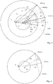
- Fig. 2 shows a schematic diagram showing the angular relationship of a first feature F1 of the trailer 2 at different points of time at which the trailer 2 has a different yaw angle YA with respect to the towing vehicle 1.
- the camera 3 may capture two or more images at different points of time at which the angular position of the trailer 2 with respect to the vehicle 1 is different. For example, an image series may be captured.
- a certain feature detected at the trailer may appear at different positions in the first and second image.
- the first feature is represented by a square.
- the upper representation of first feature (associated with the solid optical ray R connecting the feature with the camera 3) is identified in a first image
- the lower representation of first feature (associated with dashed optical ray R connecting the feature with the camera 3) is identified in a second image at a different point of time.
- calibration information of the camera 3 may be used for correlating the location of first feature in the respective image with the location of the vehicle 1, specifically a certain fix point of the vehicle 1.
- calibration information of the camera 3 may be used for determining the optical rays R connecting the first feature with the camera 3, calibration information of the camera 3 may be used to transform the location of said first feature in image coordinates into optical rays.
- the location of feature on the image is correlated with a position of a fix point of the vehicle based on calibration information of the camera 3.
- Harris Corner Detector Scale-Invariant Feature Transform (SIFT) algorithm, Speeded Up Robust Features (SURF) algorithm, Binary Robust Invariant Scalable Keypoints (BRISK) algorithm, Binary Robust Independent Elementary Features (BRIEF), Oriented FAST and rotated BRIEF (ORB) algorithm or another suitable feature detection and matching algorithm could be used.
- SIFT Scale-Invariant Feature Transform
- SURF Speeded Up Robust Features
- BRISK Binary Robust Invariant Scalable Keypoints
- BRIEF Binary Robust Independent Elementary Features
- ORB Oriented FAST and rotated BRIEF
- the feature detection and matching algorithm may detect image features that are on the trailer or not on the trailer.
- To segment the trailer features from the non-trailer features a number of different methods could be used. For instance, when driving forwards in a straight line, trailer features can be segmented from non-trailer features by looking for features that remain in the same position over time. Alternatively, the motion of background features can be modelled over time using the vehicle's known motion. This could be extracted from CAN data regarding speed and steering. Features which do not fit the Epipolar constraint of the Essential Matrix could then be considered as trailer features.
- the first feature of first and second image are projected in a common horizontal plane. More in detail, the ray between the camera 3 and determined first feature on the first image is projected onto a horizontal plane thereby obtaining a first projected feature position PFP1a. In addition, the ray between the camera 3 and determined first feature on the second image is projected onto the same horizontal plane thereby obtaining a second projected feature position PFP1b. It is worth mentioning that said projection is made in vertical direction thereby only changing the elevation angle of optical rays but not the azimuth angle.
- a first perpendicular bisector B1 is established based on said first and second projected feature positions PFP1a, PFP1b.
- the first perpendicular bisector B1 is a line being perpendicular to the line linking first and second projected feature positions PFP1a, PFP1b.
- the first perpendicular bisector B1 runs through the center of said linking line.
- Said first perpendicular bisector B1 crosses a reference axis, which is in the present embodiment the longitudinal axis of the vehicle LAV.
- Said intersection of first perpendicular bisector B1 and reference axis provides the point of rotation, around which the trailer is rotated. More in detail, said intersection provides the position of the towball 4.
- a first angle estimation ⁇ 1 is calculated.
- Said first angle estimation ⁇ 1 refers to an angle provided between a first line L1 linking first projected feature position PFP1a and the intersection of first perpendicular bisector B1 and reference axis and a second line L2 linking second projected feature position PFP1b and the intersection of first perpendicular bisector B1 and reference axis. The intersection may be indicative for the position of towball 4.
- the first angle estimation ⁇ 1 characterizes the pivot angle of the trailer 2 in a horizontal plane between the location of the first feature in the first image projected on the horizontal plane and the location of the first feature in the second image projected on said horizontal plane around said first intersection point IP1 (which is the position of towball 4).
- the first angle estimation ⁇ 1 represents the yaw angle YA of the trailer 2 around its actual point of rotation.
- Fig. 3 illustrates an embodiment similar to Fig. 2 which uses a first and a second feature F1, F2 of the trailer 2 captured at different points of time (at which the trailer 2 has a different yaw angle YA with respect to the towing vehicle 1) for establishing yaw angle YA.
- Fig. 3 On the images captured by the camera 3, multiple different features may be identifiable. As shown in Fig. 3 , said features are identified at different angular positions with respect to a fix point of the vehicle 1.
- the first feature is illustrated by a square
- the second feature is illustrated by a triangle.
- Said fix point may be the location of the camera 3 or may be the location of the towball 4.
- the upper pair of first and second feature (indicated by PFP1a, PFP2a and associated with the solid optical rays connecting the features with the camera 3) are identified in a first image
- the lower pair of first and second feature F1, F2 (indicated by PFP1b, PFP2b and associated with dashed optical rays connecting the features with the camera 3) are identified in a second image at a different point of time.
- yaw angle YA is performed analogously to the embodiment of Fig. 2 .
- the main difference is that two angle estimations ⁇ 1, ⁇ 2 are established and the yaw angle of the trailer is developed based on said two angle estimations ⁇ 1, ⁇ 2. More in detail, establishing first perpendicular bisector B1 and obtaining first angle estimation ⁇ 1 is performed like described above.
- second angle estimation ⁇ 2 is obtained by establishing third projected feature position PFP2a and fourth projected feature position PFP2b, establishing a second perpendicular bisector B2 in order to obtain a second intersection point IP2 and connecting the third projected feature position PFP2a and the fourth projected feature position PFP2b with said second intersection point IP2.
- Said third projected feature position PFP2a is obtained by projecting second feature in the first image onto said horizontal plane
- fourth projected feature position PFP2b is obtained by projecting second feature in the second image onto said horizontal plane.
- the second intersection point IP2 may be the point in which the second perpendicular bisector B2 crosses the reference axis, in the present embodiment the longitudinal axis of the vehicle LAV.
- the second angle estimation ⁇ 2 is the angle between a first line linking third projected feature position PFP2a and intersection point IP2 and a second line linking fourth projected feature position PFP2b and intersection point IP2.
- the reference axis is the longitudinal axis LAV of the towing vehicle 1, because the camera 3 as well as the towball 4 is located on said longitudinal axis LAV of the vehicle 1.
- the reference axis may be formed by a straight line linking the camera 3 and the towball 4.
- the values of first and second angle estimation ⁇ 1, ⁇ 2 can be different.
- more than two features of the trailer 2 could determined and tracked over multiple images.
- more than two images are captured at different points of time in order to enhance the result of yaw angle estimation.
- more than two angle estimations ⁇ 1, ⁇ 2 can be established for increasing the quality of yaw angle determination.
- a statistical measure may be used.
- the median of two or more angle estimations ⁇ 1, ⁇ 2 may be used to determine the yaw angle YA.
- a statistical method may be used to determine the yaw angle YA based on of two or more angle estimations ⁇ 1, ⁇ 2.
- the statistical method may be, for example, RANSAC-algorithm (RANSAC: random sample consensus) or least squares algorithm.
- yaw angle YA yaw angle YA
- those features are selected and further used for determining yaw angle YA, which provide pivot angles quite close to actual yaw angle.
- those features may be tracked in future images which provided pivot angles ⁇ 1, ⁇ 2 in a certain window around the actual yaw angle.
- the window may be defined by an upper and a lower boundary, said upper and lower boundary defining an angular window around said actual yaw angle.
- the window may span over a distance of 2° to 10°, more particular between 3° and 5°. All features which led to pivot angles within said window in the last two or more yaw angle determination steps are further tracked in the next captured images.
- the samples of said feature may be arranged on a circle segment.
- the centre of said circle segment represents the location of towball 4. Therefore, by tracking a particular trailer feature over multiple images, the location of towball 4 can be derived.
- the determination of the location of towball 4 may consider multiple trailer features tracked for a period of time over multiple images.
- Each trailer feature may correspond to a circle segment with certain centre estimation.
- the statistical method may be, for example, RANSAC-algorithm or least squares algorithm.
- Fig. 4 shows a further embodiment of geometrically determining the point of rotation without using upper-mentioned reference axis.
- first projected feature position PFP1a refers to a feature included in first image and projected in a common horizontal plane as mentioned before.
- second projected feature position PFP1b refers to a feature included in a second image
- third projected feature position PFP1c refers to a feature included in a third image.
- the first perpendicular bisector B1 refers to a line linking first and second projected feature positions PFP1a, PFP1b.
- the second perpendicular bisector B2 refer to a line linking first and third projected feature positions PFP1a, PFP1c.
- the intersection of first and second perpendicular bisectors B1, B2 defines an intersecting point IP which is indicative for the point of rotation of the trailer 2, i.e. indicative for the position of the towball 4.
- Said intersecting point IP can be used for determining the yaw angle YA of the trailer as shown in the embodiments of Fig. 2 and 3 .
- Fig. 5 shows a block diagram illustrating the method steps of a method for determining the yaw angle YA of a trailer 2 with respect to the longitudinal axis LAV of a towing vehicle 1.
- a first and a second image of the trailer is captured (S10).
- At least one feature of the trailer visible on the first and the second image is determined (S11).
- a first projected feature position and a second projected feature position are established by feature projection (S12).
- first intersection point of first perpendicular bisector with a reference axis or a further perpendicular bisector is developed (S14).
Abstract
Description
- The present invention relates generally to the field of vehicle assistance systems. More specifically, the present invention relates to a method and a system for calculating yaw angle of a trailer coupled with a towing vehicle based on image information provided by a camera of the vehicle.
- Methods for calculating the angle of a trailer with respect to the towing vehicle based on image information provided by a camera of the vehicle are already known.
- Specifically, methods are known which have low computational complexity but do not provide robust angle information in case of poor-quality images. In addition, in known methods the exact position of the towball has to be known in order to determine yaw angle.
- It is an objective of the embodiments of the invention to provide a method for calculating yaw angle of a trailer with high robustness and high reliability without having knowledge of the position of the towball. The objective is solved by the features of the independent claims. Preferred embodiments are given in the dependent claims. If not explicitly indicated otherwise, embodiments of the invention can be freely combined with each other.
- According to an aspect, the invention refers to a method for determining the yaw angle of a trailer with respect to the longitudinal axis of a towing vehicle. The method comprises the following steps:
First, at least a first and a second image of the trailer is captured using a camera. The first and second image is captured such that the orientation of the trailer with respect to the vehicle is different on the at least two images. - After capturing said images, at least a first feature of the trailer is determined. Said first feature has to be visible on first and second image. For example, the first feature may be a conspicuous first characteristic at a first location of the trailer.
- After feature determination, a ray between the camera and determined first feature on the first image is established and said ray is projected onto a horizontal plane thereby obtaining a first projected feature position. Similarly, a ray between the camera and determined first feature on the second image is established and said ray is projected onto said horizontal plane thereby obtaining a second projected feature position. Said projection of features, respectively, rays may be performed in a vertical direction, i.e. a slanted ray may be transferred in a horizontal ray without changing the azimuth.
- Based on said projections of first feature, a first perpendicular bisector is established between the location of the first projected feature position and the location of the second projected feature position. More in detail, the first perpendicular bisector may be a perpendicular straight line running through the centre of the line connecting an intersection of a first ray with a horizontal plane (e.g. at z=1) and the location of an intersection of a second ray with the horizontal plane. The first ray is determined by converting the image coordinates of the first feature in the first image into an optical ray using the cameras calibration information. The second ray is determined by converting the image coordinates of the first feature in the second image into an optical ray using the cameras calibration information. Said first perpendicular bisector may be established in a horizontal plane.
- After establishing said first perpendicular bisector, a first intersection point of first perpendicular bisector with a reference axis is determined. The reference axis may be the central longitudinal axis of the car, on which the camera and towball both lie. Thus, this intersection point represents the centre of rotation of the first feature.
- Finally, the yaw angle of the trailer is calculated based on a first angle estimation, said first angle estimation referring to the angle between a first line running from first projected feature position to said first intersection point and a second line running from second projected feature position to said first intersection point in said horizontal plane .
- Said method is advantageous because due to using two or more images and using one or more trailer features for establishing one or more perpendicular bisectors and calculating the yaw angle based on said one or more perpendicular bisectors, the results of yaw angle determination are very accurate and robust even when the detection of trailer features suffers from high noise or the quality of the images is poor. In addition, due to using a perpendicular bisector, for determining the yaw angle, the exact position of the towball can be unknown.
- According to an embodiment, on first or second image, the yaw angle of the trailer with respect to the vehicle is zero. Thereby, said image can be used as "zero-pose image", i.e. as a reference of an exact alignment of the longitudinal axis of the vehicle with the longitudinal axis of the trailer. However, also another yaw angle value can be used as reference value. If said other yaw angle is not known, the system can calculate the change in trailer angle, rather than an absolute trailer angle.
- According to an embodiment, the method further comprises the following steps:
- In addition to the first feature, a second feature of the trailer is determined which is visible on first and second image. Said second feature is arranged at a different position of the trailer than the first feature. The second feature may be a conspicuous second characteristic at a second location of the trailer.
- In addition, a ray between the camera and determined second feature on the first image is projected onto said horizontal plane thereby obtaining a third projected feature position. Similarly, a ray between the camera and determined second feature on the second image is projected onto said horizontal plane thereby obtaining a fourth projected feature position.
- Furthermore, a second perpendicular bisector is established between the location of the third projected feature position and the location of the fourth projected feature position.
- Based on said second perpendicular bisector, a second intersection point of second perpendicular bisector with said reference axis is determined.
- Based on second perpendicular bisector, a second angle estimation is established, the second angle estimation referring to the angle between a first line running from third projected feature position to said second intersection point and a second line running from fourth projected feature position to said second intersection point in said horizontal plane.
- Finally, the yaw angle is calculated based on said first and second angle estimations.
- By using two or more trailer features and multiple perpendicular bisectors, the noise and mismatches in determining the pivot angle between perpendicular bisector and reference axis can be mitigated.
- According to an embodiment, in addition to said first and second feature, at least one further feature of the trailer is used for calculating the yaw angle. Using three or more features further increases the robustness and reliability of yaw angle determination.
- According to an embodiment, the yaw angle is calculated by establishing the median value based on the at least two angle estimations. Thereby, a very stable yaw angle determination can be obtained.
- According to other embodiments, the yaw angle is calculated by establishing an average value of the at least two angle estimations or by using a statistical approach applied to said angle estimations.
- According to an embodiment, the method further comprises the step of determining an angle window. Said angle window may comprise an upper and a lower bound around said yaw angle. In addition, a set of features is determined, said features within said set of features leading to angle estimations which are located within said angle window. Said determined set of features, preferably, only features included in said set of features are used for future yaw angle calculations. So, in other words, information of previous yaw angle determinations is used to determine two or more features of the trailer which lead to angle estimations quite close to determined yaw angle (i.e. within the angle window) and to not track those features which lead to angle estimations significantly deviating from determined yaw angle (i.e. out of the angle window). Thereby, the computational complexity and accuracy of angle estimation can be significantly reduced.
- According to an embodiment, camera calibration information is used for converting the position of said first and/or second feature from local domain of the image into local domain of the vehicle. For example, having knowledge of camera position using camera calibration information, the position of a certain feature on the image can be transferred in location information depending on or being correlated with the position of the camera included or attached to the vehicle.
- According to an embodiment, the reference axis is the longitudinal axis of the towing vehicle if the camera and the towball of the vehicle are arranged in a vertically oriented plane which comprises said longitudinal axis of the towing vehicle. So, in other words, the yaw angle is determined based on angle estimations, said angle estimations referring to angles between the longitudinal axis of the towing vehicle and the established perpendicular bisectors.
- According to another embodiment, the reference axis is a straight line running between the camera and the towball if the camera and/or the towball have a lateral offset with respect to the longitudinal axis of the towing vehicle. Thereby, a lateral offset between the camera and the towball can be compensated.
- According to an embodiment, the camera is the rear view camera of the vehicle. Based on the rear view camera, images of the trailer can be captured with reduced technical effort.
- According to an embodiment, the location of the first feature is not only determined in a first and second image but also in at least a third image. The location of the first feature in the third image is different to the location of the first feature in the first image and second image. A first perpendicular bisector can be determined between the first feature in the first image and the second image. A further perpendicular bisector can be determined between the first feature in the first image and the third image. A further intersection point can then be determined on the basis of the intersection of said first perpendicular bisector and said further perpendicular bisector.
- Based on said first perpendicular bisector, a first angle estimation is calculated. The first angle estimation is the angle of rotation around said further intersection point, of the intersection of the first ray with the horizontal plane to the intersection of the second ray with the horizontal plane. The first angle estimation corresponds to the change in yaw angle of the trailer between the first image and the second image. So in other words, the point of rotation of the trailer is not determined by an intersection of first perpendicular bisector with reference axis but by intersecting at least two perpendicular bisectors obtained by tracking a feature over tree or more images.
- According to a further aspect, a system for determining the yaw angle of a trailer with respect to the longitudinal axis of a towing vehicle is disclosed. The system comprises a camera for capturing images of the trailer and a processing entity for processing said captured images. The system is further configured to execute the steps of:
- capturing at least a first and a second image of the trailer using a camera, the orientation of the trailer with respect to the vehicle being different on the at least two images;
- determining at least a first feature of the trailer which is visible on first and second image;
- projecting the ray between the camera and determined first feature on the first image onto a horizontal plane thereby obtaining a first projected feature position and projecting the ray between the camera and determined first feature on the second image onto said horizontal plane thereby obtaining a second projected feature position;
- establishing a first perpendicular bisector between the location of the first projected feature position and the location of the second projected feature position;
- determining a first intersection point of first perpendicular bisector with a reference axis;
- calculating the yaw angle based on a first angle estimation, said first angle estimation referring to the angle between a first line running from first projected feature position to said first intersection point and a second line running from second projected feature position to said first intersection point in said horizontal plane.
- Any upper-mentioned feature described as an embodiment of the method is also applicable as a system feature in a system according to the present disclosure.
- According to yet another embodiment, a vehicle comprising a system according to anyone of upper-mentioned embodiments is disclosed.
- The term "vehicle" as used in the present disclosure may refer to a car, truck, bus, train or any other crafts.
- The term "yaw angle" as used in the present disclosure may refer to a pivot angle between the longitudinal axis of the vehicle and the longitudinal axis of the trailer.
- The term "median" as used in the present disclosure may refer to a value separating a higher half from a lower half of a data sample or a probability distribution.
- The term "essentially" or "approximately" as used in the invention means deviations from the exact value by +/- 10%, preferably by +/- 5% and/or deviations in the form of changes that are insignificant for the function and/or for the traffic laws.
- Various aspects of the invention, including its particular features and advantages, will be readily understood from the following detailed description and the accompanying drawings, in which:
-
Fig. 1 shows an exemplary top view on a vehicle towing a trailer; -
Fig. 2 schematically illustrates angle estimation based on a single feature captured by camera images in different pivot angles between the trailer and the towing vehicle; -
Fig. 3 schematically illustrates angle estimations based on a first and a second feature captured by camera images in different pivot angles between the trailer and the towing vehicle; -
Fig. 4 schematically illustrates the geometrical determination of point of rotation based on first and second perpendicular bisectors obtained from a single trailer feature included in three different images; and -
Fig. 5 shows a schematic block diagram illustrating the steps of a method for determining the yaw angle of a trailer with respect to the longitudinal axis of a towing vehicle. - The present invention will now be described more fully with reference to the accompanying drawings, in which example embodiments are shown. The embodiments in the figures may relate to preferred embodiments, while all elements and features described in connection with embodiments may be used, as far as appropriate, in combination with any other embodiment and feature as discussed herein, in particular related to any other embodiment discussed further above. However, this invention should not be construed as limited to the embodiments set forth herein. Throughout the following description similar reference numerals have been used to denote similar elements, parts, items or features, when applicable.
- The features of the present invention disclosed in the specification, the claims, examples and/or the figures may both separately and in any combination thereof be material for realizing the invention in various forms thereof.
-
Fig. 1 shows a top view illustration of avehicle 1 towing atrailer 2. Thevehicle 1 comprises a longitudinal axis LAV which runs through the centre of thevehicle 1. Similarly, thetrailer 2 comprises a longitudinal axis LAT which runs through the centre of thetrailer 2. Thetrailer 2 is coupled with thevehicle 1 by means of a trailer hitch comprising atowball 4. - In certain driving situations, the longitudinal axis LAV of the
vehicle 1 and the longitudinal axis LAT of thetrailer 2 may not be aligned in parallel or may not fall into one another but the axes may confine a yaw angle YA. In other words, the yaw angle YA defines the angular deviation of the longitudinal axis LAT of thetrailer 2 with respect to the longitudinal axis LAV of thevehicle 1. The yaw angle YA may be measured in a horizontal plane which includes the longitudinal axis LAT of thetrailer 2 as well as the longitudinal axis LAV of thevehicle 1. - The knowledge of yaw angle YA is - inter alia - advantageous in trailer assistance systems, for example.
- For determining the yaw angle YA, multiple images of at least a portion of the
trailer 2 are captured by means of acamera 3. Thecamera 3 may be, for example, a rear view camera of the vehicle, which may also be used for capturing images of the surroundings of the car when driving backwards. One of the captured images may refer to a known angular arrangement of thetrailer 2 with respect to the towingvehicle 1. Said image may be used as reference for calculating the yaw angle YA. In said known angular arrangement of thetrailer 2 with respect to the towingvehicle 1, the yaw angle YA may be 0° or any other angle value. -
Fig. 2 shows a schematic diagram showing the angular relationship of a first feature F1 of thetrailer 2 at different points of time at which thetrailer 2 has a different yaw angle YA with respect to the towingvehicle 1. - The
camera 3 may capture two or more images at different points of time at which the angular position of thetrailer 2 with respect to thevehicle 1 is different. For example, an image series may be captured. - In the present example, the second image may show an orientation of the trailer with respect to the vehicle at a yaw angle YA = 0°.
- Because of the angular movement of
trailer 2 over time, a certain feature detected at the trailer may appear at different positions in the first and second image. InFig. 2 , the first feature is represented by a square. - The upper representation of first feature (associated with the solid optical ray R connecting the feature with the camera 3) is identified in a first image, the lower representation of first feature (associated with dashed optical ray R connecting the feature with the camera 3) is identified in a second image at a different point of time. For correlating the location of first feature in the respective image with the location of the
vehicle 1, specifically a certain fix point of thevehicle 1, calibration information of thecamera 3 may be used. Specifically, for determining the optical rays R connecting the first feature with thecamera 3, calibration information of thecamera 3 may be used to transform the location of said first feature in image coordinates into optical rays. In other words, for associating camera position and feature position, the location of feature on the image is correlated with a position of a fix point of the vehicle based on calibration information of thecamera 3. - Features on the trailer are located and matched using feature detection and matching algorithm. For example, the Harris Corner Detector, Scale-Invariant Feature Transform (SIFT) algorithm, Speeded Up Robust Features (SURF) algorithm, Binary Robust Invariant Scalable Keypoints (BRISK) algorithm, Binary Robust Independent Elementary Features (BRIEF), Oriented FAST and rotated BRIEF (ORB) algorithm or another suitable feature detection and matching algorithm could be used.
- The feature detection and matching algorithm may detect image features that are on the trailer or not on the trailer. To segment the trailer features from the non-trailer features a number of different methods could be used. For instance, when driving forwards in a straight line, trailer features can be segmented from non-trailer features by looking for features that remain in the same position over time. Alternatively, the motion of background features can be modelled over time using the vehicle's known motion. This could be extracted from CAN data regarding speed and steering. Features which do not fit the Epipolar constraint of the Essential Matrix could then be considered as trailer features.
- After feature identification in the respective images, the first feature of first and second image are projected in a common horizontal plane. More in detail, the ray between the
camera 3 and determined first feature on the first image is projected onto a horizontal plane thereby obtaining a first projected feature position PFP1a. In addition, the ray between thecamera 3 and determined first feature on the second image is projected onto the same horizontal plane thereby obtaining a second projected feature position PFP1b. It is worth mentioning that said projection is made in vertical direction thereby only changing the elevation angle of optical rays but not the azimuth angle. - After determining first and second projected feature positions PFP1a, PFP1b, a first perpendicular bisector B1 is established based on said first and second projected feature positions PFP1a, PFP1b. As shown in
Fig. 2 , the first perpendicular bisector B1 is a line being perpendicular to the line linking first and second projected feature positions PFP1a, PFP1b. In addition, the first perpendicular bisector B1 runs through the center of said linking line. Said first perpendicular bisector B1 crosses a reference axis, which is in the present embodiment the longitudinal axis of the vehicle LAV. Said intersection of first perpendicular bisector B1 and reference axis provides the point of rotation, around which the trailer is rotated. More in detail, said intersection provides the position of thetowball 4. - Based on said first perpendicular bisector B1, a first angle estimation α1 is calculated. Said first angle estimation α1 refers to an angle provided between a first line L1 linking first projected feature position PFP1a and the intersection of first perpendicular bisector B1 and reference axis and a second line L2 linking second projected feature position PFP1b and the intersection of first perpendicular bisector B1 and reference axis. The intersection may be indicative for the position of
towball 4. More in detail, the first angle estimation α1 characterizes the pivot angle of thetrailer 2 in a horizontal plane between the location of the first feature in the first image projected on the horizontal plane and the location of the first feature in the second image projected on said horizontal plane around said first intersection point IP1 (which is the position of towball 4). - The first angle estimation α1 represents the yaw angle YA of the
trailer 2 around its actual point of rotation. -
Fig. 3 illustrates an embodiment similar toFig. 2 which uses a first and a second feature F1, F2 of thetrailer 2 captured at different points of time (at which thetrailer 2 has a different yaw angle YA with respect to the towing vehicle 1) for establishing yaw angle YA. - On the images captured by the
camera 3, multiple different features may be identifiable. As shown inFig. 3 , said features are identified at different angular positions with respect to a fix point of thevehicle 1. The first feature is illustrated by a square, the second feature is illustrated by a triangle. Said fix point may be the location of thecamera 3 or may be the location of thetowball 4. - In
Fig. 3 , the upper pair of first and second feature (indicated by PFP1a, PFP2a and associated with the solid optical rays connecting the features with the camera 3) are identified in a first image, the lower pair of first and second feature F1, F2 (indicated by PFP1b, PFP2b and associated with dashed optical rays connecting the features with the camera 3) are identified in a second image at a different point of time. - The determination of yaw angle YA is performed analogously to the embodiment of
Fig. 2 . The main difference is that two angle estimations α1, α2 are established and the yaw angle of the trailer is developed based on said two angle estimations α1, α2. More in detail, establishing first perpendicular bisector B1 and obtaining first angle estimation α1 is performed like described above. - In addition, second angle estimation α2 is obtained by establishing third projected feature position PFP2a and fourth projected feature position PFP2b, establishing a second perpendicular bisector B2 in order to obtain a second intersection point IP2 and connecting the third projected feature position PFP2a and the fourth projected feature position PFP2b with said second intersection point IP2. Said third projected feature position PFP2a is obtained by projecting second feature in the first image onto said horizontal plane and fourth projected feature position PFP2b is obtained by projecting second feature in the second image onto said horizontal plane. The second intersection point IP2 may be the point in which the second perpendicular bisector B2 crosses the reference axis, in the present embodiment the longitudinal axis of the vehicle LAV. The second angle estimation α2 is the angle between a first line linking third projected feature position PFP2a and intersection point IP2 and a second line linking fourth projected feature position PFP2b and intersection point IP2.
- In the present embodiment, the reference axis is the longitudinal axis LAV of the towing
vehicle 1, because thecamera 3 as well as thetowball 4 is located on said longitudinal axis LAV of thevehicle 1. In other embodiments, if thecamera 3 or thetowball 4 has a lateral offset to the longitudinal axis LAV of thevehicle 1 or the lateral offset of thecamera 3 and thetowball 4 with respect to the longitudinal axis LAV of thevehicle 1 is different, the reference axis may be formed by a straight line linking thecamera 3 and thetowball 4. - Under ideal conditions, the first angle estimation α1 and the second angle estimation α2 should be equal (α1 = α2) and should represent the yaw angle YA. However, due to noise and mismatches, the values of first and second angle estimation α1, α2 can be different.
- It is worth mentioning that more than two features of the
trailer 2 could determined and tracked over multiple images. In addition, preferably, more than two images are captured at different points of time in order to enhance the result of yaw angle estimation. Thereby, more than two angle estimations α1, α2 can be established for increasing the quality of yaw angle determination. - For determining the yaw angle YA based on first and second angle estimations α1, α2 having different values, a statistical measure may be used. According to a first embodiment, the median of two or more angle estimations α1, α2 may be used to determine the yaw angle YA. According to other embodiments, a statistical method may be used to determine the yaw angle YA based on of two or more angle estimations α1, α2. The statistical method may be, for example, RANSAC-algorithm (RANSAC: random sample consensus) or least squares algorithm.
- It appeared that not all features visible on the captured images are equally suitable for calculating yaw angle YA. In order to reduce computational complexity and robustness, those features are selected and further used for determining yaw angle YA, which provide pivot angles quite close to actual yaw angle. For feature selection, only those features may be tracked in future images which provided pivot angles α1, α2 in a certain window around the actual yaw angle. For example, the window may be defined by an upper and a lower boundary, said upper and lower boundary defining an angular window around said actual yaw angle. For example, the window may span over a distance of 2° to 10°, more particular between 3° and 5°. All features which led to pivot angles within said window in the last two or more yaw angle determination steps are further tracked in the next captured images.
- In case of tracking a particular trailer feature for multiple images, due to the movement of the
trailer 2, the samples of said feature may be arranged on a circle segment. The centre of said circle segment represents the location oftowball 4. Therefore, by tracking a particular trailer feature over multiple images, the location oftowball 4 can be derived. - In order to mitigate noise, the determination of the location of
towball 4 may consider multiple trailer features tracked for a period of time over multiple images. Each trailer feature may correspond to a circle segment with certain centre estimation. By applying a statistical method on said multiple centre estimations, the actual location oftowball 4 can be developed. The statistical method may be, for example, RANSAC-algorithm or least squares algorithm. -
Fig. 4 shows a further embodiment of geometrically determining the point of rotation without using upper-mentioned reference axis. - The point of rotation is established by developing at least two perpendicular bisectors B1, B2 based on three images which show a certain feature in different angular positions with respect to the towing
vehicle 1. InFig. 4 , first projected feature position PFP1a refers to a feature included in first image and projected in a common horizontal plane as mentioned before. Similarly, the second projected feature position PFP1b refers to a feature included in a second image and third projected feature position PFP1c refers to a feature included in a third image. - The first perpendicular bisector B1 refers to a line linking first and second projected feature positions PFP1a, PFP1b. The second perpendicular bisector B2 refer to a line linking first and third projected feature positions PFP1a, PFP1c. The intersection of first and second perpendicular bisectors B1, B2 defines an intersecting point IP which is indicative for the point of rotation of the
trailer 2, i.e. indicative for the position of thetowball 4. - Said intersecting point IP can be used for determining the yaw angle YA of the trailer as shown in the embodiments of
Fig. 2 and3 . -
Fig. 5 shows a block diagram illustrating the method steps of a method for determining the yaw angle YA of atrailer 2 with respect to the longitudinal axis LAV of a towingvehicle 1. - As a first step, a first and a second image of the trailer is captured (S10).
- After image capturing, at least one feature of the trailer visible on the first and the second image is determined (S11).
- After feature determination, a first projected feature position and a second projected feature position are established by feature projection (S12).
- After feature projection, a first perpendicular bisector is established (S13).
- After establishing first perpendicular bisector, a first intersection point of first perpendicular bisector with a reference axis or a further perpendicular bisector is developed (S14).
- Finally, the yaw angle is calculated based on first angle estimation (S15).
- It should be noted that the description and drawings merely illustrate the principles of the proposed invention. Those skilled in the art will be able to implement various arrangements that, although not explicitly described or shown herein, embody the principles of the invention.
-
- 1
- vehicle
- 2
- trailer
- 3
- camera
- 4
- towball
- α1
- first angle estimation
- α2
- second angle estimation
- B1
- first perpendicular bisector
- B2
- second perpendicular bisector
- PFP1a
- projected feature position of first feature in first image
- PFP1b
- projected feature position of first feature in second image
- PFP1c
- projected feature position of first feature in third image
- PFP2a
- projected feature position of second feature in first image
- PFP2b
- projected feature position of second feature in second image
- IP
- intersecting point
- IP1
- first intersection point
- IP2
- second intersection point
- LAT
- longitudinal axis of trailer
- LAV
- longitudinal axis of vehicle
- R
- optical ray
- YA
- yaw angle
Claims (13)
- Method for determining the yaw angle (YA) of a trailer (2) with respect to the longitudinal axis (LAV) of a towing vehicle (1), the method comprising the steps of:- capturing at least a first and a second image of the trailer (2) using a camera (3), the orientation of the trailer (2) with respect to the vehicle (1) being different on the at least two images (S10);- determining at least a first feature of the trailer (2) which is visible on first and second image (S11);- projecting the ray between the camera (3) and determined first feature on the first image onto a horizontal plane thereby obtaining a first projected feature position (PFP1a) and projecting the ray between the camera (3) and determined first feature on the second image onto said horizontal plane thereby obtaining a second projected feature position (PFP1b) (S12);- establishing a first perpendicular bisector (B1) between the location of the first projected feature position (PFP1a) and the location of the second projected feature position (PFP1b) (S13);- determining a first intersection point (IP1) of first perpendicular bisector (B1) with a reference axis or a further perpendicular bisector (S14);- calculating the yaw angle (YA) based on a first angle estimation (α1), said first angle estimation (α1) referring to the angle between a first line running from first projected feature position (PFP1a) to said first intersection point (IP1) and a second line running from second projected feature position (PFP1b) to said first intersection point (IP1) in said horizontal plane (S15).
- Method according to claim 1, wherein on first or second image, the yaw angle (YA) of the trailer (2) with respect to the vehicle (1) is zero or any known yaw angle (YA) which can be used as reference angle.
- Method according to claim 1 or 2, further comprising the steps of:- determining a second feature of the trailer (2) which is visible on first and second image, wherein said second feature is arranged at a different position of the trailer (2) than the first feature;- projecting the ray between the camera (3) and determined second feature on the first image onto said horizontal plane thereby obtaining a third projected feature position (PFP2a) and projecting the ray between the camera (3) and determined second feature on the second image onto said horizontal plane thereby obtaining a fourth projected feature position (PFP2b);- establishing a second perpendicular bisector (B2) between the location of the third projected feature position (PFP2a) and the location of the fourth projected feature position (PFP2b);- determining a second intersection point (IP2) of second perpendicular bisector (B2) with said reference axis;- calculating a second angle estimation (α2), the second angle estimation (α2) referring to the angle between a first line running from third projected feature position (PFP2a) to said second intersection point (IP2) and a second line running from fourth projected feature position (PFP2b) to said second intersection point (IP2) in said horizontal plane; and- calculating the yaw angle (YA) based on said first and second angle estimations (α1, α2).
- Method according to claim 3, wherein in addition to said first and second feature, at least one further feature of the trailer (2) is used for calculating the yaw angle (YA).
- Method according to claims 3 or 4, wherein the yaw angle (YA) is calculated by establishing the median value based on the at least two angle estimations.
- Method according to anyone of preceding claims 3 to 5, wherein the yaw angle (YA) is calculated by establishing an average value of the at least two angle estimations or by using a statistical approach applied to said angle estimations.
- Method according to anyone of preceding claims, further comprising the step of determining an angle window, said angle window comprising an upper and a lower bound around yaw angle (YA), determining a set of features which lead to angle estimations within said angle window and using said determined set of features for future yaw angle (YA) calculations.
- Method according to anyone of the preceding claims, wherein camera calibration information is used for converting the position of said first and/or second feature from local domain of the image into local domain of the vehicle (1).
- Method according to anyone of the preceding claims, wherein the reference axis is the longitudinal axis (LAV) of the towing vehicle (1) if the camera (3) and the towball (4) of the vehicle (1) are arranged in a vertically oriented plane which comprises said longitudinal axis (LAV) of the towing vehicle (1).
- Method according to anyone of the preceding claims, wherein the reference axis is a straight line running between the camera (3) and the towball (4) if the camera (3) and/or the towball (4) have a lateral offset with respect to the longitudinal axis (LAV) of the towing vehicle (1).
- Method according to anyone of the preceding claims, wherein the camera (3) is the rear view camera of the vehicle (1).
- System for determining the yaw angle (YA) of a trailer (2) with respect to the longitudinal axis (LAV) of a towing vehicle (1), the system comprising a camera (3) for capturing images of the trailer (2) and a processing entity for processing said captured images, the system further being configured to execute the steps of:- capturing at least a first and a second image of the trailer (2) using a camera (3), the orientation of the trailer (2) with respect to the vehicle (1) being different on the at least two images (S10);- determining at least a first feature of the trailer (2) which is visible on first and second image (S11);- projecting the ray between the camera (3) and determined first feature on the first image onto a horizontal plane thereby obtaining a first projected feature position (PFP1a) and projecting the ray between the camera (3) and determined first feature on the second image onto said horizontal plane thereby obtaining a second projected feature position (PFP1b) (S12);- establishing a first perpendicular bisector (B1) between the location of the first projected feature position (PFP1a) and the location of the second projected feature position (PFP1b) (S13);- determining a first intersection point (IP1) of first perpendicular bisector (B1) with a reference axis or a further perpendicular bisector (S14);- calculating the yaw angle (YA) based on a first angle estimation (α1), said first angle estimation (α1) referring to the angle between a first line running from first projected feature position (PFP1a) to said first intersection point (IP1) and a second line running from second projected feature position (PFP1b) to said first intersection point (IP1) in said horizontal plane (S15).
- Vehicle comprising a system according to claim 12.
Priority Applications (5)
| Application Number | Priority Date | Filing Date | Title |
|---|---|---|---|
| EP20167188.0A EP3889905A1 (en) | 2020-03-31 | 2020-03-31 | Method and system for calculating vehicle trailer angle |
| PCT/EP2020/084109 WO2021197650A1 (en) | 2020-03-31 | 2020-12-01 | Method and system for calculating vehicle trailer angle |
| CN202080098804.3A CN115298696A (en) | 2020-03-31 | 2020-12-01 | Method and system for calculating angle of trailer of vehicle |
| JP2022549860A JP2023514845A (en) | 2020-03-31 | 2020-12-01 | Method and system for calculating angle between vehicle and trailer |
| US17/995,141 US20230173998A1 (en) | 2020-03-31 | 2020-12-01 | Method and system for calculating vehicle trailer angle |
Applications Claiming Priority (1)
| Application Number | Priority Date | Filing Date | Title |
|---|---|---|---|
| EP20167188.0A EP3889905A1 (en) | 2020-03-31 | 2020-03-31 | Method and system for calculating vehicle trailer angle |
Publications (1)
| Publication Number | Publication Date |
|---|---|
| EP3889905A1 true EP3889905A1 (en) | 2021-10-06 |
Family
ID=70110143
Family Applications (1)
| Application Number | Title | Priority Date | Filing Date |
|---|---|---|---|
| EP20167188.0A Pending EP3889905A1 (en) | 2020-03-31 | 2020-03-31 | Method and system for calculating vehicle trailer angle |
Country Status (5)
| Country | Link |
|---|---|
| US (1) | US20230173998A1 (en) |
| EP (1) | EP3889905A1 (en) |
| JP (1) | JP2023514845A (en) |
| CN (1) | CN115298696A (en) |
| WO (1) | WO2021197650A1 (en) |
Citations (4)
| Publication number | Priority date | Publication date | Assignee | Title |
|---|---|---|---|---|
| DE102016117284A1 (en) * | 2016-09-14 | 2018-03-15 | Connaught Electronics Ltd. | Determining a position of a trailer hitch |
| US20180251154A1 (en) * | 2011-01-26 | 2018-09-06 | Magna Electronics Inc. | Trailering assist system with trailer angle detection |
| US20180276839A1 (en) * | 2017-03-22 | 2018-09-27 | Magna Electronics Inc. | Trailer angle detection system for vehicle |
| EP3537382A1 (en) * | 2018-03-09 | 2019-09-11 | Continental Automotive GmbH | Device and method for calculating a vehicle trailer pose using a camera |
-
2020
- 2020-03-31 EP EP20167188.0A patent/EP3889905A1/en active Pending
- 2020-12-01 JP JP2022549860A patent/JP2023514845A/en active Pending
- 2020-12-01 US US17/995,141 patent/US20230173998A1/en active Pending
- 2020-12-01 WO PCT/EP2020/084109 patent/WO2021197650A1/en active Application Filing
- 2020-12-01 CN CN202080098804.3A patent/CN115298696A/en active Pending
Patent Citations (4)
| Publication number | Priority date | Publication date | Assignee | Title |
|---|---|---|---|---|
| US20180251154A1 (en) * | 2011-01-26 | 2018-09-06 | Magna Electronics Inc. | Trailering assist system with trailer angle detection |
| DE102016117284A1 (en) * | 2016-09-14 | 2018-03-15 | Connaught Electronics Ltd. | Determining a position of a trailer hitch |
| US20180276839A1 (en) * | 2017-03-22 | 2018-09-27 | Magna Electronics Inc. | Trailer angle detection system for vehicle |
| EP3537382A1 (en) * | 2018-03-09 | 2019-09-11 | Continental Automotive GmbH | Device and method for calculating a vehicle trailer pose using a camera |
Also Published As
| Publication number | Publication date |
|---|---|
| US20230173998A1 (en) | 2023-06-08 |
| CN115298696A (en) | 2022-11-04 |
| JP2023514845A (en) | 2023-04-11 |
| WO2021197650A1 (en) | 2021-10-07 |
Similar Documents
| Publication | Publication Date | Title |
|---|---|---|
| Zhou et al. | Reliable scale estimation and correction for monocular visual odometry | |
| US10452999B2 (en) | Method and a device for generating a confidence measure for an estimation derived from images captured by a camera mounted on a vehicle | |
| CN108510530B (en) | Three-dimensional point cloud matching method and system | |
| US10909395B2 (en) | Object detection apparatus | |
| JP2002123818A (en) | Peripheral obstacle detecting device for vehicle | |
| US20230322032A1 (en) | Method and system for calculating vehicle trailer angle | |
| Fanani et al. | Multimodal scale estimation for monocular visual odometry | |
| CN113359125A (en) | Data fusion method and device and data processing equipment | |
| Nishigaki et al. | Vision-based lateral position improvement of radar detections | |
| EP3889905A1 (en) | Method and system for calculating vehicle trailer angle | |
| EP3889903A1 (en) | Method and system for calculating vehicle trailer angle | |
| Müller et al. | LACI: Low-effort automatic calibration of infrastructure sensors | |
| CN114384505A (en) | Method and device for determining radar deflection angle | |
| Yu et al. | An improved phase correlation method for stop detection of autonomous driving | |
| US20230215035A1 (en) | Method and system for calculating vehicle trailer angle | |
| Cheda et al. | Camera egomotion estimation in the ADAS context | |
| JP2001108434A (en) | Method and apparatus for measuring distance | |
| JPWO2021197650A5 (en) | ||
| JPWO2021197651A5 (en) | ||
| Wang et al. | A method to calibrate vehicle-mounted cameras under urban traffic scenes | |
| Mariotti et al. | Spherical formulation of moving object geometric constraints for monocular fisheye cameras | |
| Borkar et al. | A new multi-camera approach for lane departure warning | |
| JPWO2021197652A5 (en) | ||
| Gbreel et al. | A Comparative Study on Feature Descriptors in the Visual Odometry Stack for State Estimation | |
| Hou et al. | Automotive Radar Missing Dimension Reconstruction from Motion |
Legal Events
| Date | Code | Title | Description |
|---|---|---|---|
| PUAI | Public reference made under article 153(3) epc to a published international application that has entered the european phase |
Free format text: ORIGINAL CODE: 0009012 |
|
| STAA | Information on the status of an ep patent application or granted ep patent |
Free format text: STATUS: THE APPLICATION HAS BEEN PUBLISHED |
|
| AK | Designated contracting states |
Kind code of ref document: A1 Designated state(s): AL AT BE BG CH CY CZ DE DK EE ES FI FR GB GR HR HU IE IS IT LI LT LU LV MC MK MT NL NO PL PT RO RS SE SI SK SM TR |
|
| STAA | Information on the status of an ep patent application or granted ep patent |
Free format text: STATUS: REQUEST FOR EXAMINATION WAS MADE |
|
| 17P | Request for examination filed |
Effective date: 20220406 |
|
| RBV | Designated contracting states (corrected) |
Designated state(s): AL AT BE BG CH CY CZ DE DK EE ES FI FR GB GR HR HU IE IS IT LI LT LU LV MC MK MT NL NO PL PT RO RS SE SI SK SM TR |
|
| RAP1 | Party data changed (applicant data changed or rights of an application transferred) |
Owner name: CONTINENTAL AUTONOMOUS MOBILITY GERMANY GMBH |