EP3889801A1 - System for assessing cause of damage to structure, method for assessing cause of damage, and server for assessing cause of damage - Google Patents
System for assessing cause of damage to structure, method for assessing cause of damage, and server for assessing cause of damage Download PDFInfo
- Publication number
- EP3889801A1 EP3889801A1 EP19891104.2A EP19891104A EP3889801A1 EP 3889801 A1 EP3889801 A1 EP 3889801A1 EP 19891104 A EP19891104 A EP 19891104A EP 3889801 A1 EP3889801 A1 EP 3889801A1
- Authority
- EP
- European Patent Office
- Prior art keywords
- damage
- information
- unit
- similar
- cause
- Prior art date
- Legal status (The legal status is an assumption and is not a legal conclusion. Google has not performed a legal analysis and makes no representation as to the accuracy of the status listed.)
- Withdrawn
Links
Images



Classifications
-
- G—PHYSICS
- G06—COMPUTING OR CALCULATING; COUNTING
- G06T—IMAGE DATA PROCESSING OR GENERATION, IN GENERAL
- G06T7/00—Image analysis
- G06T7/0002—Inspection of images, e.g. flaw detection
- G06T7/0004—Industrial image inspection
- G06T7/001—Industrial image inspection using an image reference approach
-
- E—FIXED CONSTRUCTIONS
- E01—CONSTRUCTION OF ROADS, RAILWAYS, OR BRIDGES
- E01D—CONSTRUCTION OF BRIDGES, ELEVATED ROADWAYS OR VIADUCTS; ASSEMBLY OF BRIDGES
- E01D22/00—Methods or apparatus for repairing or strengthening existing bridges ; Methods or apparatus for dismantling bridges
-
- G—PHYSICS
- G01—MEASURING; TESTING
- G01M—TESTING STATIC OR DYNAMIC BALANCE OF MACHINES OR STRUCTURES; TESTING OF STRUCTURES OR APPARATUS, NOT OTHERWISE PROVIDED FOR
- G01M5/00—Investigating the elasticity of structures, e.g. deflection of bridges or air-craft wings
- G01M5/0008—Investigating the elasticity of structures, e.g. deflection of bridges or air-craft wings of bridges
-
- G—PHYSICS
- G01—MEASURING; TESTING
- G01M—TESTING STATIC OR DYNAMIC BALANCE OF MACHINES OR STRUCTURES; TESTING OF STRUCTURES OR APPARATUS, NOT OTHERWISE PROVIDED FOR
- G01M5/00—Investigating the elasticity of structures, e.g. deflection of bridges or air-craft wings
- G01M5/0091—Investigating the elasticity of structures, e.g. deflection of bridges or air-craft wings by using electromagnetic excitation or detection
-
- G—PHYSICS
- G01—MEASURING; TESTING
- G01N—INVESTIGATING OR ANALYSING MATERIALS BY DETERMINING THEIR CHEMICAL OR PHYSICAL PROPERTIES
- G01N21/00—Investigating or analysing materials by the use of optical means, i.e. using sub-millimetre waves, infrared, visible or ultraviolet light
- G01N21/84—Systems specially adapted for particular applications
- G01N21/88—Investigating the presence of flaws or contamination
- G01N21/8851—Scan or image signal processing specially adapted therefor, e.g. for scan signal adjustment, for detecting different kinds of defects, for compensating for structures, markings, edges
-
- G—PHYSICS
- G06—COMPUTING OR CALCULATING; COUNTING
- G06F—ELECTRIC DIGITAL DATA PROCESSING
- G06F16/00—Information retrieval; Database structures therefor; File system structures therefor
- G06F16/50—Information retrieval; Database structures therefor; File system structures therefor of still image data
- G06F16/53—Querying
-
- G—PHYSICS
- G06—COMPUTING OR CALCULATING; COUNTING
- G06F—ELECTRIC DIGITAL DATA PROCESSING
- G06F16/00—Information retrieval; Database structures therefor; File system structures therefor
- G06F16/50—Information retrieval; Database structures therefor; File system structures therefor of still image data
- G06F16/58—Retrieval characterised by using metadata, e.g. metadata not derived from the content or metadata generated manually
- G06F16/5866—Retrieval characterised by using metadata, e.g. metadata not derived from the content or metadata generated manually using information manually generated, e.g. tags, keywords, comments, manually generated location and time information
-
- G—PHYSICS
- G06—COMPUTING OR CALCULATING; COUNTING
- G06F—ELECTRIC DIGITAL DATA PROCESSING
- G06F18/00—Pattern recognition
- G06F18/20—Analysing
- G06F18/22—Matching criteria, e.g. proximity measures
-
- G—PHYSICS
- G06—COMPUTING OR CALCULATING; COUNTING
- G06Q—INFORMATION AND COMMUNICATION TECHNOLOGY [ICT] SPECIALLY ADAPTED FOR ADMINISTRATIVE, COMMERCIAL, FINANCIAL, MANAGERIAL OR SUPERVISORY PURPOSES; SYSTEMS OR METHODS SPECIALLY ADAPTED FOR ADMINISTRATIVE, COMMERCIAL, FINANCIAL, MANAGERIAL OR SUPERVISORY PURPOSES, NOT OTHERWISE PROVIDED FOR
- G06Q50/00—Information and communication technology [ICT] specially adapted for implementation of business processes of specific business sectors, e.g. utilities or tourism
- G06Q50/08—Construction
-
- G—PHYSICS
- G06—COMPUTING OR CALCULATING; COUNTING
- G06T—IMAGE DATA PROCESSING OR GENERATION, IN GENERAL
- G06T3/00—Geometric image transformations in the plane of the image
- G06T3/40—Scaling of whole images or parts thereof, e.g. expanding or contracting
- G06T3/4038—Image mosaicing, e.g. composing plane images from plane sub-images
-
- G—PHYSICS
- G06—COMPUTING OR CALCULATING; COUNTING
- G06T—IMAGE DATA PROCESSING OR GENERATION, IN GENERAL
- G06T7/00—Image analysis
- G06T7/0002—Inspection of images, e.g. flaw detection
-
- G—PHYSICS
- G06—COMPUTING OR CALCULATING; COUNTING
- G06T—IMAGE DATA PROCESSING OR GENERATION, IN GENERAL
- G06T7/00—Image analysis
- G06T7/60—Analysis of geometric attributes
-
- G—PHYSICS
- G06—COMPUTING OR CALCULATING; COUNTING
- G06T—IMAGE DATA PROCESSING OR GENERATION, IN GENERAL
- G06T7/00—Image analysis
- G06T7/70—Determining position or orientation of objects or cameras
- G06T7/73—Determining position or orientation of objects or cameras using feature-based methods
- G06T7/74—Determining position or orientation of objects or cameras using feature-based methods involving reference images or patches
-
- G—PHYSICS
- G06—COMPUTING OR CALCULATING; COUNTING
- G06V—IMAGE OR VIDEO RECOGNITION OR UNDERSTANDING
- G06V10/00—Arrangements for image or video recognition or understanding
- G06V10/70—Arrangements for image or video recognition or understanding using pattern recognition or machine learning
- G06V10/74—Image or video pattern matching; Proximity measures in feature spaces
- G06V10/761—Proximity, similarity or dissimilarity measures
-
- G—PHYSICS
- G06—COMPUTING OR CALCULATING; COUNTING
- G06T—IMAGE DATA PROCESSING OR GENERATION, IN GENERAL
- G06T2207/00—Indexing scheme for image analysis or image enhancement
- G06T2207/20—Special algorithmic details
- G06T2207/20212—Image combination
-
- G—PHYSICS
- G06—COMPUTING OR CALCULATING; COUNTING
- G06T—IMAGE DATA PROCESSING OR GENERATION, IN GENERAL
- G06T2207/00—Indexing scheme for image analysis or image enhancement
- G06T2207/30—Subject of image; Context of image processing
- G06T2207/30108—Industrial image inspection
- G06T2207/30132—Masonry; Concrete
-
- G—PHYSICS
- G06—COMPUTING OR CALCULATING; COUNTING
- G06T—IMAGE DATA PROCESSING OR GENERATION, IN GENERAL
- G06T2207/00—Indexing scheme for image analysis or image enhancement
- G06T2207/30—Subject of image; Context of image processing
- G06T2207/30181—Earth observation
- G06T2207/30184—Infrastructure
-
- G—PHYSICS
- G06—COMPUTING OR CALCULATING; COUNTING
- G06V—IMAGE OR VIDEO RECOGNITION OR UNDERSTANDING
- G06V2201/00—Indexing scheme relating to image or video recognition or understanding
- G06V2201/06—Recognition of objects for industrial automation
Definitions
- the present invention relates to a structure damage cause estimation system, a structure damage cause estimation method, and a structure damage cause estimation server. More particularly, the present invention relates to a damage cause estimation system, a damage cause estimation method, and a damage cause estimation server that estimate a damage cause by using a database including results about damage causes of structures inspected in the past.
- JP2015-95143A describes a system for assisting evaluation of a defect of infrastructure.
- the system generates a recommendation ranking list of pieces of defect information having high degrees of similarity to defect information to be processed, on the basis of co-occurrence information which is a co-occurrence probability for defect information and of the defect information to be processed.
- JP2015-95143A describes that the defect information may include a structure type name or, as other information, "a volume of traffic", “information on the structure", “construction year”, etc. in addition to a damage item name such as a crack or a free lime.
- the volume of traffic or the information on the structure is merely one condition used for identifying a damage cause.
- a system for simply obtaining a damage cause is desired.
- the present invention is made in view of such a circumstance, and an object of the present invention is to provide a structure damage cause estimation system, a structure damage cause estimation method, and a structure damage cause estimation server that extract and list damage examples similar to a damage state of a structure subjected to a current inspection by using a database including damage causes identified in past inspections so as to enable estimation of a damage cause with a high probability.
- a structure damage cause estimation system includes a database that has data of a captured image of damage of a structure before repair and a damage cause of the structure; an image acquisition unit that acquires a captured image of a target structure to be inspected; an actual size information acquisition unit that acquires an actual size of a characteristic portion of the target structure in the captured image or an actual length of the target structure; a damage detection unit that detects damage from the captured image acquired by the image acquisition unit, and calculates a degree of the damage, based on information acquired by the actual size information acquisition unit; a similar damage extraction unit that determines a degree of similarity of the damage detected by the damage detection unit to damage of the structure in the database, and extracts one or more kinds of similar damage for which the degree of similarity is high; and a damage cause presentation unit that presents damage causes of the kinds of similar damage extracted by the similar damage extraction unit.
- a structure damage cause estimation method includes an image acquisition step of, with an image acquisition unit, acquiring a captured image of a target structure to be inspected; an actual size information acquisition step of, with an actual size information acquisition unit, acquiring an actual size of a characteristic portion of the target structure in the captured image or an actual length of the target structure; a damage detection step of, with a damage detection unit, detecting damage from the captured image acquired in the image acquisition step, and calculating a degree of the damage, based on information acquired in the actual size information acquisition step; a similar damage extraction step of, with a similar damage extraction unit, by using a database having data of a captured image of damage of a structure before the repair and a damage cause of the structure, determining a degree of similarity of the damage detected in the damage detection step to damage of the structure in the database, and extracting one or more kinds of similar damage for which the degree of similarity is high; and a damage cause presentation step of, with a damage cause presentation unit
- a structure damage cause estimation server is a structure damage cause estimation server that is connected to a user terminal via a network and estimates a damage cause of a target structure to be inspected and that includes a database that has data of a captured image of damage of a structure before repair and a damage cause of the structure; an image acquisition unit that acquires a captured image of a target structure to be inspected; an actual size information acquisition unit that acquires an actual size of a characteristic portion of the target structure in the captured image or an actual length of the target structure; a damage detection unit that detects damage from the captured image acquired by the image acquisition unit, and calculates a degree of the damage, based on information acquired by the actual size information acquisition unit; a similar damage extraction unit that determines a degree of similarity of the damage detected by the damage detection unit to damage of the structure in the database, and extracts one or more kinds of similar damage for which the degree of similarity is high; a damage cause presentation unit that presents damage causes of the kinds of
- the structure damage cause estimation system is capable of extracting damage examples similar to a damage state of a target structure subjected to an inspection by using a database including damage causes identified in past inspections.
- a user can refer to the result when identifying the damage cause.
- the accuracy of estimation of the damage cause can be increased.
- Fig. 1 is a perspective view of a bridge 1, which is a structure, viewed from below.
- the bridge 1 illustrated in Fig. 1 has a three-dimensional structure constituted by main girders 2, cross beams 3, sway bracings 4, lateral bracing 5, and deck slabs 6. These members are connected to each other with bolts, rivets, welding, and so on.
- the deck slabs 6 on which vehicles or the like travel are placed above the main girders 2 and so on.
- reinforced concrete deck slabs are typically used.
- the main girders 2 are members laid between abutments or piers to support the load of vehicles or the like on the deck slabs 6.
- the main girders 2 have surfaces (vertical surfaces) orthogonal to surfaces (horizontal surfaces) of the deck slabs 6.
- the cross beams 3 are members that connect the plurality of main girders 2 to each other so that the main girders 2 support the load.
- the sway bracings 4 and the lateral bracings 5 are members that connect the main girders 2 to each other to resist the lateral load imposed by winds and earthquakes.
- the structure is not limited to a bridge, and may be a tunnel, a building, and a road or the like.
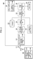
- Fig. 2 is a block diagram illustrating schematic configurations of a damage cause estimation system 100 according to one embodiment of the present invention and of a digital camera 200.
- the damage cause estimation system 100 has a database 110, an image acquisition unit 115, an actual size information acquisition unit 120, a damage detection unit 125, a similar damage extraction unit 130, and a damage cause presentation unit 135.
- the damage cause estimation system 100 may include an information acquisition unit 140 that acquires information on a target structure to be inspected, namely, other information such as a damage cause and structure information held in association with the structure in the database 110, a display control unit 145 that displays estimated damage causes, and an output unit 150 that outputs the estimated damage causes.
- the damage cause estimation system 100 is a system that detects damage from an image obtained by capturing an image of a target structure to be inspected and estimates a damage cause of the damage.
- the damage cause estimation system 100 is applicable to a digital camera, a smartphone, a tablet terminal, a personal computer, and the like.
- the image acquired by the image acquisition unit 115 can be captured by the digital camera 200.
- the digital camera 200 may be placed in a housing different from that of the damage cause estimation system 100, or may be integrated with the damage cause estimation system 100.
- the digital camera 200 may be incorporated as a portion of the damage cause estimation system 100 and may constitute the structure damage cause estimation system according to the present embodiment.
- the digital camera 200 captures an image with an imaging optical system 210 including an imaging lens (not illustrated) and an imaging element (not illustrated).
- the imaging element include a charge coupled device (CCD) imaging element and a complementary metal-oxide semiconductor (CMOS) imaging element.
- CCD charge coupled device
- CMOS complementary metal-oxide semiconductor
- Color filters of red (R), green (G), and blue (B) are disposed on a light-receiving surface of the imaging element.
- the imaging element is capable of acquiring a color image of a photographic subject on the basis of signals of the respective colors.
- the digital camera 200 wirelessly communicates with the damage cause estimation system 100 via a wireless communication unit 220 and an antenna 222, so that the captured image is input to the image acquisition unit 115 and is subjected to processing described below.
- the image acquisition unit 115 includes a panoramic combination unit 116 and may use an image resulting from panoramic combination processing performed on the group of images by the panoramic combination unit 116.
- the digital camera 200 may be, for example, a general-purpose compact digital camera having the number of pixels of about 5000 ⁇ 4000 pixels.
- the damage cause estimation system 100 is constituted mainly by the database 110, the image acquisition unit 115, the actual size information acquisition unit 120, the damage detection unit 125, the similar damage extraction unit 130, and the damage cause presentation unit 135. These are connected to each other to transmit and receive necessary information.
- the damage cause estimation system 100 wirelessly communicates with the digital camera 200 via an antenna 117, and acquires a captured image captured by the digital camera 200.
- the database 110 is a recording means for storing a captured image of a structure before repair and a damage cause of the structure.
- example of the damage cause include (1) deterioration due to fatigue (repeatedly imposed load), salt, neutralization, alkali-silica reaction, frost damage, chemical erosion, and so on; (2) construction-relating factors such as heat of hydration and drying shrinkage caused during construction; and (3) structural factors such as application of an excessive external force and an inappropriate design.
- examples of the damage cause include (1) deterioration due to fatigue (repeatedly imposed load), salt, and so on; and (2) structural factors such as application of an excessive external force and an inappropriate design.
- the information stored in the database 110 can include damage information of the structure.
- the damage information of the structure can include a type of damage, a position of the damage, and a degree of the damage (such as a length, a width, an area, a density, a depth, or the like, or an average value or maximum value thereof).
- the information stored in the database 110 may include, as other information, structure information, environment information, and history information.
- the structure information include (1) a type of the structure which is, for example, a girder bridge, a rigid-frame bridge, a truss bridge, an arch bridge, a cable-stayed bridge, a suspension bridge, or the like in the case of a bridge; (2) a type of a member which is, for example, a deck slab, a pier, an abutment, a girder, or the like in the case of a bridge; and (3) a material, which is, for example, steel, reinforced concrete, prestressed concrete (PC), or the like.
- PC prestressed concrete
- Examples of the environment information include a daily, monthly, yearly, or cumulative volume of traffic, a distance from the sea, and climates such as an average temperature, an average humidity, a rainfall, and a snowfall.
- Examples of the history information include construction conditions such as temperatures during construction; the number of elapsed years; a repair history; a disaster history of earthquakes, typhoons, floods, and so on; and monitoring information on deflection, a vibration amplitude, a vibration period, and so on.
- the database 110 may further store at least one of captured images or damage information of damage of a structure at a plurality of past time points. By storing the past captured images and the damage information, a chronological change of the target structure can also be used in determination of the degree of similarity when the degree of similarity is determined.
- the image acquisition unit 115 acquires a captured image of a target structure to be inspected.
- an image is acquired in units of structures or in units of members of the target structure.
- the image acquisition unit 115 acquires a captured image of the bridge 1 from the digital camera 200 (or a recording medium, a network, or the like).
- the captured image may be an image obtained by capturing the entire structure in a single image-capturing operation, or may be a plurality of images obtained by capturing images of segments of the target structure as a group of images when a region for which the captured image is to be acquired cannot be covered by a single image-capturing operation with a predetermined resolution.
- the panoramic combination unit 116 performs panoramic combination processing. In the panoramic combination processing, correspondence points between images are detected, and the captured images are combined together on the basis of the correspondence points between the images.
- the image acquisition unit 115 may periodically acquire the captured image of the target structure to acquire chronological images of the target structure.
- the similar damage extraction unit 130 described later can also use a chronological change in the target structure to determine the degree of similarity. Note that it is sufficient that at least an image at the previous inspection and an image at the current inspection are acquired as the chronological images.
- the actual size information acquisition unit 120 acquires an actual size of a characteristic portion of the target structure in the captured image acquired by the image acquisition unit 115 or an actual length of the target structure.
- the actual length of the target structure can be obtained by acquiring a resolution representing an actual length of the target structure per unit pixel of the captured image.
- the actual length of the target structure can be obtained by capturing an image of the structure together with an object with which the length of the structure is obtained, or by capturing an image by projecting a scale.
- the damage detection unit 125 detects damage from the captured image acquired by the image acquisition unit 115.
- the damage detection unit 125 also calculates a degree of the damage on the basis of information acquired by the actual size information acquisition unit 120.
- the damage detection unit 125 detects, as damage to be detected, damage such as a crack, water leakage, free lime, peeling, exposure of a reinforcement steel, and delamination. In the case where the structure is a steel member, the damage detection unit 125 detects damage such as fracture, corrosion, and deterioration of anti-corrosion function. The damage detection unit 125 detects any one or more of these kinds of damage.
- the detection can be performed through detection using a machine-learning-based detector and a detection algorithm.
- items to be measured for detecting a crack include a position, a size, a direction, a range, a shape, and the like. These items can be set according to conditions such as a type and characteristics of the structure.
- a crack can be detected by using various methods. For example, a crack detection method described in JP4006007B can be used. This method is a crack detection method having a step of creating a wavelet image and a step of determining a crack region on the basis of the wavelet image.
- a wavelet coefficient corresponding to two densities to be compared is calculated, wavelet coefficients in the cases where the two densities are each changed are calculated to create a wavelet coefficient table, and wavelet transform is performed on an input image obtained by capturing an image of a concrete surface subjected to crack detection.
- a wavelet coefficient corresponding to an average density of neighboring pixels in a local region and to a density of a pixel of interest in the wavelet coefficient table is set as a threshold value, and a crack region and a non-crack region are determined by comparing the wavelet coefficient of the pixel of interest with the threshold value.
- the similar damage extraction unit 130 determines a degree of similarity on the basis of the type of the damage, the position of the damage, and the degree of the damage, and extracts one or more kinds of similar damage having high degrees of similarity from the database 110.
- the similar damage extraction unit 130 may determine the degree of similarity on the basis of chronological changes in the position of the damage and the degree of damage in addition to the damage information.
- the similar damage extraction unit 130 may determine the degree of similarity on the basis of any one or more of the structure information, the environment information, the history information, the disaster information, and the inspection information in the database 110, and extract similar damage.
- a distance between damage of an inspection-target structure and damage of another structure stored in the database is calculated in a feature space having the above information as feature vectors. Damage having this distance equal to or less than a certain threshold value is extracted as similar damage.
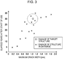
- Fig. 3 is a graph illustrating a concept of determining a degree of similarity.
- the feature space defined by feature vectors can be a multi-dimensional space defined by parameters selected from the group consisting of the type of the damage, the position of the damage, the degree of the damage, chronological changes in the position of the damage and the degree of damage, the structure information, the environment information, the history information, the disaster information, and the inspection information which are used when the degree of similarity is determined. Note that Fig. 3 illustrates a two-dimensional space to simplify the description.
- the maximum crack width is plotted as a first feature vector on a lateral axis, and the number of elapsed years after the start of use is plotted as a second feature vector on a vertical axis.
- a predetermined distance from damage of the target structure to be inspected is set as a threshold value, and damage having a distance less than or equal to this threshold value is extracted as similar damage.
- a circle centered at the target structure and represented by a broken line indicates that the distance is less than or equal to the threshold value.
- a distance (Euclidean distance) based on parameters that are not weighted may be used, or a distance (Mahalanobis distance) based on weighted parameters may be used. How which parameter is weighted may be determined by a statistical method such as principal component analysis.
- the damage cause presentation unit 135 presents damage causes of similar damage extracted by the similar damage extraction unit 130.
- the damage causes can be presented in the following manner.
- Fig. 4 is a diagram describing a method of presenting damage causes.
- Pieces of information on similar damage are presented in descending order of the degree of similarity.
- pieces of information on kinds of similar damage having high degrees of similarity for example, pieces of information on kinds of similar damage having the top 100 degrees of similarity are listed in descending order of the evaluation score (EXAMPLE 1).
- Occurrence frequencies (percentages) of damage causes of kinds of similar damage having high degrees of similarity for example, kinds of similar damage having the top 100 degrees of similarity among the kinds of similar damage extracted by the similar damage extraction unit 130 are calculated and presented along with the respective damage causes.
- the damage cause is fatigue in seven cases
- the damage cause is salt in two cases
- the damage cause is alkali-silica reaction in one case.
- the damage causes are represented as fatigue (70%), salt (20%), and alkali-silica reaction (10%).
- Damage causes may be listed for the similar damage extracted by the similar damage extraction unit 130 without rearranging the order.
- Fig. 4 illustrates the 10 damage examples A to J as examples of damage to simplify the illustration. However, in practice, it is preferable to extract 100 damage examples up to the 100th place as described above and present the damage causes.
- the information to be presented is not the damage causes alone, and information such as the captured image and the damage information (the type of damage, the position of damage, the degree of the damage (such as length, width, or area) of the target structure can be presented.
- the damage causes to be presented are causes of damage that can be fixed by repair.
- deteriorations include fatigue, salt damage, neutralization, alkali-silica reaction, frost damage, chemical erosion, and so on.
- Construction-relating factors include heat of hydration, drying shrinkage, and so on caused during construction.
- Structural factors include application of an excessive external force, an inappropriate design, and so on.
- deteriorations include fatigue, salt damage, and so on.
- Structural factors include application of an excessive external force and an inappropriate design.
- the information acquisition unit 140 acquires structure information, environment information, and history information (hereinafter, also referred to as "information on the structure or the like") of the target structure to be inspected.
- structure information, the environment information, and the history information information substantially the same as the information included in the database 110 described above is acquired.
- the information acquisition unit 140 When the information acquisition unit 140 acquires the information, the information can be input using an operation section (not illustrated).
- the operation section includes a keyboard and a mouse as input devices.
- a monitor display unit 146 described later has a touch panel, the operation section also includes the touch panel.
- the user can input information on the structure or the like through these devices and the screen of the monitor display unit 146.
- the information acquisition unit 140 acquires the input information on the structure or the like.
- the display control unit 145 includes the monitor display unit 146, and causes the monitor display unit 146 to display information such as the acquired captured image, the damage causes of the extracted similar damage, and the information on the target structure to be inspected.
- the display control unit 145 controls the matters relating to the display screen such as information to be displayed on the monitor display unit 146.
- the monitor display unit 146 is a display device such as a liquid crystal display.
- the output unit 150 outputs the damage causes presented by the damage cause presentation unit 135 as text data or table data.
- the output unit 150 also outputs the acquired captured image. These pieces of information may be output as data of a figure.
- FIG. 5 is a flowchart illustrating a procedure of the damage cause estimation method.
- An image acquisition step is a step of acquiring a captured image of a target structure to be inspected (step S12).
- the captured image is obtained by the digital camera 200.
- the damage cause estimation system 100 acquires a captured image via the digital camera 200 (the imaging optical system 210, the wireless communication unit 220, and the antenna 222), the antenna 117, and the image acquisition unit 115.
- the captured image is a plurality of captured images (a group of image images)
- panoramic combining processing for combining the plurality of captured images into a single image is performed.
- combination information for example, calculation of correspondence points between the captured images and calculation of a projective transformation matrix on the basis of the correspondence points, is performed, and the images are combined on the basis of the correspondence points.
- an actual size of a characteristic portion of the target structure in the captured image acquired in the image acquisition step or an actual length of the target structure is acquired (step S14).
- a damage detection step is a step of detecting damage from the captured image acquired in the image acquisition step (step S16). A degree of the damage is also calculated on the basis of the information acquired in the actual size information acquisition step.
- a similar damage extraction step degrees of similarity of the damage detected in the damage detection step to kinds of damage of structures in the database 110 are determined using the database 110, and one or more kinds of similar damage having high degrees of similarity are extracted (step S18).
- the structure may be periodically inspected after the repair.
- This inspection history may be recorded in the database 110.
- the degree of similarity may be determined on the basis of the chronological change based on this inspection record.
- a damage cause presentation step damage causes of the kinds of similar damage extracted in the similar damage extraction step are presented (step S20).
- the damage causes can be presented so that the damage cause is easily determined, by using a method of presenting damage causes in descending order of the degree of similarity for the respective kinds of similar damage or of presenting a percentage of each damage cause with respect to the extracted kinds of similar damage together with the damage cause.
- Fig. 6 is a block diagram illustrating a schematic configuration of a damage cause estimation server 300 according to one embodiment of the present invention.
- the same components as those of the damage cause estimation system 100 illustrated in Fig. 2 are denoted by the same reference signs, and description thereof will be omitted below.
- the damage cause estimation server 300 has the database 110, the image acquisition unit 115, the actual size information acquisition unit 120, the damage detection unit 125, the similar damage extraction unit 130, the damage cause presentation unit 135, and a communication unit 305.
- the damage cause estimation server 300 may also include the information acquisition unit 140 that acquires information on a target structure to be inspected, namely, other information such as structure information of the structure held in the database 110.
- the damage cause estimation server 300 includes the communication unit 305 and is connected to a user terminal 400 via a network.
- the communication unit 305 includes a reception unit 306 and a transmission unit 307.
- the reception unit 306 receives a captured image of a target structure to be inspected from the user terminal 400.
- the received captured image is transmitted to the image acquisition unit 115 and is processed in substantially the same manner as in the damage cause estimation system 100 illustrated in Fig. 2 .
- the damage cause presentation unit 135 presents damage causes of the target structure to be inspected.
- the reception unit 306 may also receive information on the structure or the like input to the user terminal 400 and transmit the information to the information acquisition unit 140.
- the information may be used by the similar damage extraction unit 130 to determine the degree of similarity.
- the damage causes presented by the damage cause presentation unit 135 are transmitted to the communication unit 305.
- the transmission unit 307 transmits the presented damage causes to the user terminal 400.
- a user checks the presented damage causes on the user terminal 400. In this manner, the accuracy of determining the damage cause can be increased.
- the structure damage cause estimation system, the structure damage cause estimation method, and the structure damage cause estimation server enable a user to determine a damage cause with a high accuracy by extracting kinds of similar damage from the database 110 and presenting damage causes of the extracted kinds of similar damage.
- the hardware structure of the processing units that perform various processes is various processors as follows.
- the various processors include, for example, a central processing unit (CPU) which is a general-purpose processor that executes software (program) to function as the various processing units; a programmable logic device (PLD) which is a processor whose circuit configuration is changeable after manufacture, such as a field programmable gate array (FPGA); and a dedicated electric circuitry which is a processor having a circuit configuration designed exclusively for executing a specific process, such as an application-specific integrated circuit (ASIC).
- CPU central processing unit
- PLD programmable logic device
- FPGA field programmable gate array
- ASIC application-specific integrated circuit
- a single processing unit may be implemented by one of these various processors, or may be implemented by two or more processors of the same kind or of different kinds (for example, a plurality of FPGAs or a combination of a CPU and an FPGA).
- the plurality of processing units may be implemented by a single processor. Examples in which the plurality of processing units are implemented by a single processor include a first configuration, as exemplified by a computer such as a client or a server, in which a combination of one or more CPUs and software constitutes a single processor and this processor functions as the plurality of processing units.
- the examples also include a second configuration, as exemplified by a system on chip (SoC) or the like, in which a processor that implements the functions of the entire system including the plurality of processing units with a single integrated circuit (IC) chip is used.
- SoC system on chip
- IC integrated circuit
- a structure damage cause estimation system including:
Landscapes
- Engineering & Computer Science (AREA)
- Theoretical Computer Science (AREA)
- Physics & Mathematics (AREA)
- General Physics & Mathematics (AREA)
- Computer Vision & Pattern Recognition (AREA)
- Data Mining & Analysis (AREA)
- General Engineering & Computer Science (AREA)
- Databases & Information Systems (AREA)
- Artificial Intelligence (AREA)
- Evolutionary Computation (AREA)
- General Health & Medical Sciences (AREA)
- Health & Medical Sciences (AREA)
- Quality & Reliability (AREA)
- Life Sciences & Earth Sciences (AREA)
- Medical Informatics (AREA)
- Multimedia (AREA)
- Software Systems (AREA)
- Bioinformatics & Cheminformatics (AREA)
- Evolutionary Biology (AREA)
- Computing Systems (AREA)
- Bioinformatics & Computational Biology (AREA)
- Business, Economics & Management (AREA)
- Aviation & Aerospace Engineering (AREA)
- Library & Information Science (AREA)
- Geometry (AREA)
- Economics (AREA)
- Tourism & Hospitality (AREA)
- Immunology (AREA)
- Pathology (AREA)
- Electromagnetism (AREA)
- Analytical Chemistry (AREA)
- Chemical & Material Sciences (AREA)
- Signal Processing (AREA)
- General Business, Economics & Management (AREA)
- Biochemistry (AREA)
- Strategic Management (AREA)
- Primary Health Care (AREA)
- Marketing (AREA)
- Human Resources & Organizations (AREA)
- Structural Engineering (AREA)
Abstract
Description
- The present invention relates to a structure damage cause estimation system, a structure damage cause estimation method, and a structure damage cause estimation server. More particularly, the present invention relates to a damage cause estimation system, a damage cause estimation method, and a damage cause estimation server that estimate a damage cause by using a database including results about damage causes of structures inspected in the past.
- Social infrastructure such as a bridge needs to be periodically inspected. In a periodic inspection, a damage cause is estimated and identified from a result of a visual inspection, and diagnosis such as determination of a countermeasure class (determination of the necessity of repair) is made.
- Since estimation and identification of a damage cause require advanced skills and experience, the results may vary among inspectors (diagnosis-making persons). Thus, there may be cases where estimation of the damage cause is difficult. Shortage of skilled inspectors is also a factor that hinders an appropriate damage cause from being estimated.
- As a system for evaluating a defect of infrastructure including a structure such as a road, for example,
JP2015-95143A -
JP2015-95143A - The present invention is made in view of such a circumstance, and an object of the present invention is to provide a structure damage cause estimation system, a structure damage cause estimation method, and a structure damage cause estimation server that extract and list damage examples similar to a damage state of a structure subjected to a current inspection by using a database including damage causes identified in past inspections so as to enable estimation of a damage cause with a high probability.
- To accomplish the object of the present invention, a structure damage cause estimation system according to an aspect of the present invention includes a database that has data of a captured image of damage of a structure before repair and a damage cause of the structure; an image acquisition unit that acquires a captured image of a target structure to be inspected; an actual size information acquisition unit that acquires an actual size of a characteristic portion of the target structure in the captured image or an actual length of the target structure; a damage detection unit that detects damage from the captured image acquired by the image acquisition unit, and calculates a degree of the damage, based on information acquired by the actual size information acquisition unit; a similar damage extraction unit that determines a degree of similarity of the damage detected by the damage detection unit to damage of the structure in the database, and extracts one or more kinds of similar damage for which the degree of similarity is high; and a damage cause presentation unit that presents damage causes of the kinds of similar damage extracted by the similar damage extraction unit.
- To accomplish the object of the present invention, a structure damage cause estimation method according to an aspect of the present invention includes an image acquisition step of, with an image acquisition unit, acquiring a captured image of a target structure to be inspected; an actual size information acquisition step of, with an actual size information acquisition unit, acquiring an actual size of a characteristic portion of the target structure in the captured image or an actual length of the target structure; a damage detection step of, with a damage detection unit, detecting damage from the captured image acquired in the image acquisition step, and calculating a degree of the damage, based on information acquired in the actual size information acquisition step; a similar damage extraction step of, with a similar damage extraction unit, by using a database having data of a captured image of damage of a structure before the repair and a damage cause of the structure, determining a degree of similarity of the damage detected in the damage detection step to damage of the structure in the database, and extracting one or more kinds of similar damage for which the degree of similarity is high; and a damage cause presentation step of, with a damage cause presentation unit, presenting damage causes of the kinds of similar damage extracted in the similar damage extraction step.
- To accomplish the object of the present invention, a structure damage cause estimation server according to an aspect of the present invention is a structure damage cause estimation server that is connected to a user terminal via a network and estimates a damage cause of a target structure to be inspected and that includes a database that has data of a captured image of damage of a structure before repair and a damage cause of the structure; an image acquisition unit that acquires a captured image of a target structure to be inspected; an actual size information acquisition unit that acquires an actual size of a characteristic portion of the target structure in the captured image or an actual length of the target structure; a damage detection unit that detects damage from the captured image acquired by the image acquisition unit, and calculates a degree of the damage, based on information acquired by the actual size information acquisition unit; a similar damage extraction unit that determines a degree of similarity of the damage detected by the damage detection unit to damage of the structure in the database, and extracts one or more kinds of similar damage for which the degree of similarity is high; a damage cause presentation unit that presents damage causes of the kinds of similar damage extracted by the similar damage extraction unit; and a communication unit having a reception unit that receives the captured image from the user terminal via the network, and a transmission unit that transmits the damage causes presented by the damage cause presentation unit to the user terminal.
- The structure damage cause estimation system according to an aspect of the present invention is capable of extracting damage examples similar to a damage state of a target structure subjected to an inspection by using a database including damage causes identified in past inspections. By extracting damage having a high degree of similarity to the damage of the target subjected to the inspection from the database and listing damage causes, a user can refer to the result when identifying the damage cause. Thus, the accuracy of estimation of the damage cause can be increased.
-
-
Fig. 1 is an external view of a bridge view from below; -
Fig. 2 is a block diagram illustrating a configuration of a structure damage cause estimation system; -
Fig. 3 is a graph illustrating a concept of determining a degree of similarity of damage; -
Fig. 4 is a diagram describing a method of presenting damage causes; -
Fig. 5 is a flowchart of a structure damage cause estimation method; and -
Fig. 6 is a block diagram illustrating a configuration of a structure damage cause estimation server. - A structure damage cause estimation system, a structure damage cause estimation method, and a structure damage cause estimation server according to one embodiment of the present invention will be described below with reference to the accompanying drawings. Structure of Bridge
-
Fig. 1 is a perspective view of abridge 1, which is a structure, viewed from below. Thebridge 1 illustrated inFig. 1 has a three-dimensional structure constituted bymain girders 2,cross beams 3,sway bracings 4,lateral bracing 5, anddeck slabs 6. These members are connected to each other with bolts, rivets, welding, and so on. The deck slabs 6 on which vehicles or the like travel are placed above themain girders 2 and so on. As the deck slabs 6, reinforced concrete deck slabs are typically used. Themain girders 2 are members laid between abutments or piers to support the load of vehicles or the like on thedeck slabs 6. Themain girders 2 have surfaces (vertical surfaces) orthogonal to surfaces (horizontal surfaces) of thedeck slabs 6. Thecross beams 3 are members that connect the plurality ofmain girders 2 to each other so that themain girders 2 support the load. Thesway bracings 4 and thelateral bracings 5 are members that connect themain girders 2 to each other to resist the lateral load imposed by winds and earthquakes. In the present embodiment, the structure is not limited to a bridge, and may be a tunnel, a building, and a road or the like. -
Fig. 2 is a block diagram illustrating schematic configurations of a damagecause estimation system 100 according to one embodiment of the present invention and of adigital camera 200. - The damage cause
estimation system 100 according to the present embodiment has adatabase 110, animage acquisition unit 115, an actual sizeinformation acquisition unit 120, adamage detection unit 125, a similardamage extraction unit 130, and a damage causepresentation unit 135. The damage causeestimation system 100 may include aninformation acquisition unit 140 that acquires information on a target structure to be inspected, namely, other information such as a damage cause and structure information held in association with the structure in thedatabase 110, adisplay control unit 145 that displays estimated damage causes, and anoutput unit 150 that outputs the estimated damage causes. - The damage cause
estimation system 100 is a system that detects damage from an image obtained by capturing an image of a target structure to be inspected and estimates a damage cause of the damage. The damage causeestimation system 100 is applicable to a digital camera, a smartphone, a tablet terminal, a personal computer, and the like. The image acquired by theimage acquisition unit 115 can be captured by thedigital camera 200. Thedigital camera 200 may be placed in a housing different from that of the damage causeestimation system 100, or may be integrated with the damagecause estimation system 100. Thedigital camera 200 may be incorporated as a portion of the damage causeestimation system 100 and may constitute the structure damage cause estimation system according to the present embodiment. - The
digital camera 200 captures an image with an imagingoptical system 210 including an imaging lens (not illustrated) and an imaging element (not illustrated). Examples of the imaging element include a charge coupled device (CCD) imaging element and a complementary metal-oxide semiconductor (CMOS) imaging element. Color filters of red (R), green (G), and blue (B) are disposed on a light-receiving surface of the imaging element. Thus, the imaging element is capable of acquiring a color image of a photographic subject on the basis of signals of the respective colors. Thedigital camera 200 wirelessly communicates with the damage causeestimation system 100 via awireless communication unit 220 and anantenna 222, so that the captured image is input to theimage acquisition unit 115 and is subjected to processing described below. - If an image of the entire structure or portion serving as a photographic subject cannot be captured in a single image-capturing operation performed with the
digital camera 200, a group of images is acquired by capturing images of segments of the structure or portion serving as the photographic subject. Theimage acquisition unit 115 includes apanoramic combination unit 116 and may use an image resulting from panoramic combination processing performed on the group of images by thepanoramic combination unit 116. Thedigital camera 200 may be, for example, a general-purpose compact digital camera having the number of pixels of about 5000 × 4000 pixels. - The damage
cause estimation system 100 is constituted mainly by thedatabase 110, theimage acquisition unit 115, the actual sizeinformation acquisition unit 120, thedamage detection unit 125, the similardamage extraction unit 130, and the damage causepresentation unit 135. These are connected to each other to transmit and receive necessary information. The damage causeestimation system 100 wirelessly communicates with thedigital camera 200 via anantenna 117, and acquires a captured image captured by thedigital camera 200. - The
database 110 is a recording means for storing a captured image of a structure before repair and a damage cause of the structure. - As damage causes of a concrete member, example of the damage cause include (1) deterioration due to fatigue (repeatedly imposed load), salt, neutralization, alkali-silica reaction, frost damage, chemical erosion, and so on; (2) construction-relating factors such as heat of hydration and drying shrinkage caused during construction; and (3) structural factors such as application of an excessive external force and an inappropriate design. As damage causes of a steel member, examples of the damage cause include (1) deterioration due to fatigue (repeatedly imposed load), salt, and so on; and (2) structural factors such as application of an excessive external force and an inappropriate design.
- The information stored in the
database 110 can include damage information of the structure. The damage information of the structure can include a type of damage, a position of the damage, and a degree of the damage (such as a length, a width, an area, a density, a depth, or the like, or an average value or maximum value thereof). - The information stored in the
database 110 may include, as other information, structure information, environment information, and history information. Examples of the structure information include (1) a type of the structure which is, for example, a girder bridge, a rigid-frame bridge, a truss bridge, an arch bridge, a cable-stayed bridge, a suspension bridge, or the like in the case of a bridge; (2) a type of a member which is, for example, a deck slab, a pier, an abutment, a girder, or the like in the case of a bridge; and (3) a material, which is, for example, steel, reinforced concrete, prestressed concrete (PC), or the like. - Examples of the environment information include a daily, monthly, yearly, or cumulative volume of traffic, a distance from the sea, and climates such as an average temperature, an average humidity, a rainfall, and a snowfall.
- Examples of the history information include construction conditions such as temperatures during construction; the number of elapsed years; a repair history; a disaster history of earthquakes, typhoons, floods, and so on; and monitoring information on deflection, a vibration amplitude, a vibration period, and so on.
- The
database 110 may further store at least one of captured images or damage information of damage of a structure at a plurality of past time points. By storing the past captured images and the damage information, a chronological change of the target structure can also be used in determination of the degree of similarity when the degree of similarity is determined. - The
image acquisition unit 115 acquires a captured image of a target structure to be inspected. As the captured image, an image is acquired in units of structures or in units of members of the target structure. - The
image acquisition unit 115 acquires a captured image of thebridge 1 from the digital camera 200 (or a recording medium, a network, or the like). The captured image may be an image obtained by capturing the entire structure in a single image-capturing operation, or may be a plurality of images obtained by capturing images of segments of the target structure as a group of images when a region for which the captured image is to be acquired cannot be covered by a single image-capturing operation with a predetermined resolution. When a plurality of images are acquired, thepanoramic combination unit 116 performs panoramic combination processing. In the panoramic combination processing, correspondence points between images are detected, and the captured images are combined together on the basis of the correspondence points between the images. - The
image acquisition unit 115 may periodically acquire the captured image of the target structure to acquire chronological images of the target structure. When detecting similar damage, the similardamage extraction unit 130 described later can also use a chronological change in the target structure to determine the degree of similarity. Note that it is sufficient that at least an image at the previous inspection and an image at the current inspection are acquired as the chronological images. - The actual size
information acquisition unit 120 acquires an actual size of a characteristic portion of the target structure in the captured image acquired by theimage acquisition unit 115 or an actual length of the target structure. In a method for obtaining an actual length of a structure, the actual length of the target structure can be obtained by acquiring a resolution representing an actual length of the target structure per unit pixel of the captured image. In another method, the actual length of the target structure can be obtained by capturing an image of the structure together with an object with which the length of the structure is obtained, or by capturing an image by projecting a scale. - The
damage detection unit 125 detects damage from the captured image acquired by theimage acquisition unit 115. Thedamage detection unit 125 also calculates a degree of the damage on the basis of information acquired by the actual sizeinformation acquisition unit 120. - In the case where the structure is a concrete member, the
damage detection unit 125 detects, as damage to be detected, damage such as a crack, water leakage, free lime, peeling, exposure of a reinforcement steel, and delamination. In the case where the structure is a steel member, thedamage detection unit 125 detects damage such as fracture, corrosion, and deterioration of anti-corrosion function. Thedamage detection unit 125 detects any one or more of these kinds of damage. - The detection can be performed through detection using a machine-learning-based detector and a detection algorithm.
- For example, items to be measured for detecting a crack include a position, a size, a direction, a range, a shape, and the like. These items can be set according to conditions such as a type and characteristics of the structure. A crack can be detected by using various methods. For example, a crack detection method described in
JP4006007B - The similar
damage extraction unit 130 determines a degree of similarity on the basis of the type of the damage, the position of the damage, and the degree of the damage, and extracts one or more kinds of similar damage having high degrees of similarity from thedatabase 110. - The similar
damage extraction unit 130 may determine the degree of similarity on the basis of chronological changes in the position of the damage and the degree of damage in addition to the damage information. The similardamage extraction unit 130 may determine the degree of similarity on the basis of any one or more of the structure information, the environment information, the history information, the disaster information, and the inspection information in thedatabase 110, and extract similar damage. - In determination of the degree of similarity, a distance between damage of an inspection-target structure and damage of another structure stored in the database is calculated in a feature space having the above information as feature vectors. Damage having this distance equal to or less than a certain threshold value is extracted as similar damage.
-
Fig. 3 is a graph illustrating a concept of determining a degree of similarity. The feature space defined by feature vectors can be a multi-dimensional space defined by parameters selected from the group consisting of the type of the damage, the position of the damage, the degree of the damage, chronological changes in the position of the damage and the degree of damage, the structure information, the environment information, the history information, the disaster information, and the inspection information which are used when the degree of similarity is determined. Note thatFig. 3 illustrates a two-dimensional space to simplify the description. - In
Fig. 3 , the maximum crack width is plotted as a first feature vector on a lateral axis, and the number of elapsed years after the start of use is plotted as a second feature vector on a vertical axis. A predetermined distance from damage of the target structure to be inspected is set as a threshold value, and damage having a distance less than or equal to this threshold value is extracted as similar damage. InFig. 3 , a circle centered at the target structure and represented by a broken line indicates that the distance is less than or equal to the threshold value. - When similar damage is extracted, a distance (Euclidean distance) based on parameters that are not weighted may be used, or a distance (Mahalanobis distance) based on weighted parameters may be used. How which parameter is weighted may be determined by a statistical method such as principal component analysis.
- The damage
cause presentation unit 135 presents damage causes of similar damage extracted by the similardamage extraction unit 130. As for a method for presenting the damage causes, for example, the damage causes can be presented in the following manner.Fig. 4 is a diagram describing a method of presenting damage causes. - (1) Pieces of information on similar damage are presented in descending order of the degree of similarity.
- Among kinds of similar damage extracted by the similar
damage extraction unit 130, pieces of information on kinds of similar damage having high degrees of similarity, for example, pieces of information on kinds of similar damage having the top 100 degrees of similarity are listed in descending order of the evaluation score (EXAMPLE 1). - (2) Percentages of damage causes of similar damage are presented.
- Occurrence frequencies (percentages) of damage causes of kinds of similar damage having high degrees of similarity, for example, kinds of similar damage having the top 100 degrees of similarity among the kinds of similar damage extracted by the similar
damage extraction unit 130 are calculated and presented along with the respective damage causes. For example, in EXAMPLE 2 ofFig. 4 , among 10 kinds of similar damage (A to J), the damage cause is fatigue in seven cases, the damage cause is salt in two cases, and the damage cause is alkali-silica reaction in one case. Thus, the damage causes are represented as fatigue (70%), salt (20%), and alkali-silica reaction (10%). - (3) Damage causes in the database are listed for the extracted similar damage.
- Damage causes may be listed for the similar damage extracted by the similar
damage extraction unit 130 without rearranging the order. -
Fig. 4 illustrates the 10 damage examples A to J as examples of damage to simplify the illustration. However, in practice, it is preferable to extract 100 damage examples up to the 100th place as described above and present the damage causes. - The information to be presented is not the damage causes alone, and information such as the captured image and the damage information (the type of damage, the position of damage, the degree of the damage (such as length, width, or area) of the target structure can be presented.
- In one embodiment of the present invention, the damage causes to be presented are causes of damage that can be fixed by repair. For example, in the case of examples of the damage cause of a concrete member, deteriorations include fatigue, salt damage, neutralization, alkali-silica reaction, frost damage, chemical erosion, and so on. Construction-relating factors include heat of hydration, drying shrinkage, and so on caused during construction. Structural factors include application of an excessive external force, an inappropriate design, and so on. In the case of examples of the damage cause of a steel member, deteriorations include fatigue, salt damage, and so on. Structural factors include application of an excessive external force and an inappropriate design.
- The
information acquisition unit 140 acquires structure information, environment information, and history information (hereinafter, also referred to as "information on the structure or the like") of the target structure to be inspected. As the structure information, the environment information, and the history information, information substantially the same as the information included in thedatabase 110 described above is acquired. - When the
information acquisition unit 140 acquires the information, the information can be input using an operation section (not illustrated). The operation section includes a keyboard and a mouse as input devices. When amonitor display unit 146 described later has a touch panel, the operation section also includes the touch panel. The user can input information on the structure or the like through these devices and the screen of themonitor display unit 146. Theinformation acquisition unit 140 acquires the input information on the structure or the like. - The
display control unit 145 includes themonitor display unit 146, and causes themonitor display unit 146 to display information such as the acquired captured image, the damage causes of the extracted similar damage, and the information on the target structure to be inspected. Thedisplay control unit 145 controls the matters relating to the display screen such as information to be displayed on themonitor display unit 146. Themonitor display unit 146 is a display device such as a liquid crystal display. - The
output unit 150 outputs the damage causes presented by the damagecause presentation unit 135 as text data or table data. Theoutput unit 150 also outputs the acquired captured image. These pieces of information may be output as data of a figure. - A damage cause estimation method used by the damage cause estimation system will be described.
Fig. 5 is a flowchart illustrating a procedure of the damage cause estimation method. - An image acquisition step is a step of acquiring a captured image of a target structure to be inspected (step S12). The captured image is obtained by the
digital camera 200. The damage causeestimation system 100 acquires a captured image via the digital camera 200 (the imagingoptical system 210, thewireless communication unit 220, and the antenna 222), theantenna 117, and theimage acquisition unit 115. - In a case where the captured image is a plurality of captured images (a group of image images), panoramic combining processing for combining the plurality of captured images into a single image is performed. In combination of the captured images, calculation of combination information, for example, calculation of correspondence points between the captured images and calculation of a projective transformation matrix on the basis of the correspondence points, is performed, and the images are combined on the basis of the correspondence points.
- In an actual size information acquisition step, an actual size of a characteristic portion of the target structure in the captured image acquired in the image acquisition step or an actual length of the target structure is acquired (step S14).
- A damage detection step is a step of detecting damage from the captured image acquired in the image acquisition step (step S16). A degree of the damage is also calculated on the basis of the information acquired in the actual size information acquisition step.
- In a similar damage extraction step, degrees of similarity of the damage detected in the damage detection step to kinds of damage of structures in the
database 110 are determined using thedatabase 110, and one or more kinds of similar damage having high degrees of similarity are extracted (step S18). - As for the extraction of similar damage, the structure may be periodically inspected after the repair. This inspection history may be recorded in the
database 110. The degree of similarity may be determined on the basis of the chronological change based on this inspection record. - In a damage cause presentation step, damage causes of the kinds of similar damage extracted in the similar damage extraction step are presented (step S20). In presentation of the damage causes, the damage causes can be presented so that the damage cause is easily determined, by using a method of presenting damage causes in descending order of the degree of similarity for the respective kinds of similar damage or of presenting a percentage of each damage cause with respect to the extracted kinds of similar damage together with the damage cause.
-
Fig. 6 is a block diagram illustrating a schematic configuration of a damagecause estimation server 300 according to one embodiment of the present invention. The same components as those of the damagecause estimation system 100 illustrated inFig. 2 are denoted by the same reference signs, and description thereof will be omitted below. - The damage
cause estimation server 300 according to the present embodiment has thedatabase 110, theimage acquisition unit 115, the actual sizeinformation acquisition unit 120, thedamage detection unit 125, the similardamage extraction unit 130, the damagecause presentation unit 135, and acommunication unit 305. The damagecause estimation server 300 may also include theinformation acquisition unit 140 that acquires information on a target structure to be inspected, namely, other information such as structure information of the structure held in thedatabase 110. - The damage
cause estimation server 300 includes thecommunication unit 305 and is connected to auser terminal 400 via a network. Thecommunication unit 305 includes areception unit 306 and atransmission unit 307. Thereception unit 306 receives a captured image of a target structure to be inspected from theuser terminal 400. The received captured image is transmitted to theimage acquisition unit 115 and is processed in substantially the same manner as in the damagecause estimation system 100 illustrated inFig. 2 . The damagecause presentation unit 135 presents damage causes of the target structure to be inspected. Thereception unit 306 may also receive information on the structure or the like input to theuser terminal 400 and transmit the information to theinformation acquisition unit 140. The information may be used by the similardamage extraction unit 130 to determine the degree of similarity. - The damage causes presented by the damage
cause presentation unit 135 are transmitted to thecommunication unit 305. Thetransmission unit 307 transmits the presented damage causes to theuser terminal 400. A user checks the presented damage causes on theuser terminal 400. In this manner, the accuracy of determining the damage cause can be increased. - As described above, the structure damage cause estimation system, the structure damage cause estimation method, and the structure damage cause estimation server according to the present embodiments enable a user to determine a damage cause with a high accuracy by extracting kinds of similar damage from the
database 110 and presenting damage causes of the extracted kinds of similar damage. - In each of the embodiments described above, the hardware structure of the processing units that perform various processes, such as the
database 110, theimage acquisition unit 115, thepanoramic combination unit 116, the actual sizeinformation acquisition unit 120, thedamage detection unit 125, the similardamage extraction unit 130, the damagecause presentation unit 135, theinformation acquisition unit 140, thedisplay control unit 145, theoutput unit 150, thecommunication unit 305, thereception unit 306, and thetransmission unit 307 is various processors as follows. The various processors include, for example, a central processing unit (CPU) which is a general-purpose processor that executes software (program) to function as the various processing units; a programmable logic device (PLD) which is a processor whose circuit configuration is changeable after manufacture, such as a field programmable gate array (FPGA); and a dedicated electric circuitry which is a processor having a circuit configuration designed exclusively for executing a specific process, such as an application-specific integrated circuit (ASIC). - A single processing unit may be implemented by one of these various processors, or may be implemented by two or more processors of the same kind or of different kinds (for example, a plurality of FPGAs or a combination of a CPU and an FPGA). In addition, the plurality of processing units may be implemented by a single processor. Examples in which the plurality of processing units are implemented by a single processor include a first configuration, as exemplified by a computer such as a client or a server, in which a combination of one or more CPUs and software constitutes a single processor and this processor functions as the plurality of processing units. The examples also include a second configuration, as exemplified by a system on chip (SoC) or the like, in which a processor that implements the functions of the entire system including the plurality of processing units with a single integrated circuit (IC) chip is used. As described above, the various processing units are implemented using one or more of the various processors described above in terms of the hardware structure.
- Further, the hardware structure of these various processors is, more specifically, electric circuitry in which circuit elements such as semiconductor elements are combined.
- The description above can be grasped as a structure damage cause estimation system described in
Appendix 1 below. - A structure damage cause estimation system including:
- a memory that stores data of a captured image of damage of a structure before repair and a damage cause of the structure; and
- a processor, wherein
- the processor
- acquires a captured image of a target structure to be inspected;
- acquires an actual size of a characteristic portion of the target structure in the captured image or an actual length of the target structure;
- detects damage from the captured image acquired, and calculates a degree of the damage, based on information acquired;
- determines a degree of similarity of the detected damage to damage of the structure stored in the memory, and extracts one or more kinds of similar damage for which the degree of similarity is high; and
- presents damage causes of the extracted kinds of similar damage.
-
- 1
- bridge
- 2
- main girder
- 3
- cross beam
- 4
- sway bracing
- 5
- lateral bracing
- 6
- deck slab
- 100
- damage cause estimation system
- 110
- database
- 115
- image acquisition unit
- 116
- panoramic combination unit
- 117,222
- antenna
- 120
- actual size information acquisition unit
- 125
- damage detection unit
- 130
- similar damage extraction unit
- 135
- damage cause presentation unit
- 140
- information acquisition unit
- 145
- display control unit
- 146
- monitor display unit
- 150
- output unit
- 200
- digital camera
- 210
- imaging optical system
- 220
- wireless communication unit
- 300
- damage cause estimation server
- 305
- communication unit
- 306
- reception unit
- 307
- transmission unit
- 400
- user terminal
Claims (10)
- A structure damage cause estimation system comprising:a database that has data of a captured image of damage of a structure before repair and a damage cause of the structure;an image acquisition unit that acquires a captured image of a target structure to be inspected;an actual size information acquisition unit that acquires an actual size of a characteristic portion of the target structure in the captured image or an actual length of the target structure;a damage detection unit that detects damage from the captured image acquired by the image acquisition unit, and calculates a degree of the damage, based on information acquired by the actual size information acquisition unit;a similar damage extraction unit that determines a degree of similarity of the damage detected by the damage detection unit to damage of the structure in the database, and extracts one or more kinds of similar damage for which the degree of similarity is high; anda damage cause presentation unit that presents damage causes of the kinds of similar damage extracted by the similar damage extraction unit.
- The structure damage cause estimation system according to claim 1, wherein the database has damage information of the structure, the damage information including a type of the damage, a position of the damage, and the degree of the damage.
- The structure damage cause estimation system according to claim 2, further comprising:an information acquisition unit that acquires at least one or more pieces of information of structure information, environment information, or history information of the target structure, whereinthe database has at least one or more pieces of information of structure information, environment information, or history information of the structure, andthe similar damage extraction unit determines the degree of similarity, based on the at least one or more pieces of information of the structure information, the environment information, or the history information acquired by the information acquisition unit in addition to the damage information.
- The structure damage cause estimation system according to any one of claims 1 to 3, wherein the damage cause presentation unit presents the damage causes of the kinds of similar damage and pieces of information on the kinds of similar damage in descending order of the degree of similarity.
- The structure damage cause estimation system according to any one of claims 1 to 3, wherein the damage cause presentation unit calculates occurrence frequencies of the respective damage causes of the kinds of similar damage extracted by the similar damage extraction unit and presents the damage causes and the occurrence frequencies.
- The structure damage cause estimation system according to any one of claims 1 to 5, whereinthe image acquisition unit acquires a group of images obtained by capturing images of segments of the target structure, andthe image acquisition unit has a panoramic combination unit that performs panoramic combination processing on the group of images.
- The structure damage cause estimation system according to any one of claims 1 to 6, whereinthe database has at least one of captured images or pieces of damage information of the damage of the structure at a plurality of past time points,the image acquisition unit acquires chronological images of the target structure, andthe similar damage extraction unit uses a chronological change in a position of the damage or the degree of the damage obtained from the captured images or the pieces of damage information of the damage of the structure at the plurality of past time points to determine the degree of similarity.
- The structure damage cause estimation system according to any one of claims 1 to 7, wherein the similar damage extraction unit weights each piece of information.
- A structure damage cause estimation method comprising:an image acquisition step of, with an image acquisition unit, acquiring a captured image of a target structure to be inspected;an actual size information acquisition step of, with an actual size information acquisition unit, acquiring an actual size of a characteristic portion of the target structure in the captured image or an actual length of the target structure;a damage detection step of, with a damage detection unit, detecting damage from the captured image acquired in the image acquisition step, and calculating a degree of the damage, based on information acquired in the actual size information acquisition step;a similar damage extraction step of, with a similar damage extraction unit, by using a database having data of a captured image of damage of a structure before the repair and a damage cause of the structure, determining a degree of similarity of the damage detected in the damage detection step to damage of the structure in the database, and extracting one or more kinds of similar damage for which the degree of similarity is high; anda damage cause presentation step of, with a damage cause presentation unit, presenting damage causes of the kinds of similar damage extracted in the similar damage extraction step.
- A structure damage cause estimation server that is connected to a user terminal via a network and estimates a damage cause of a target structure to be inspected, the structure damage cause estimation server comprising:a database that has data of a captured image of damage of a structure before repair and a damage cause of the structure;an image acquisition unit that acquires a captured image of a target structure to be inspected;an actual size information acquisition unit that acquires an actual size of a characteristic portion of the target structure in the captured image or an actual length of the target structure;a damage detection unit that detects damage from the captured image acquired by the image acquisition unit, and calculates a degree of the damage, based on information acquired by the actual size information acquisition unit;a similar damage extraction unit that determines a degree of similarity of the damage detected by the damage detection unit to damage of the structure in the database, and extracts one or more kinds of similar damage for which the degree of similarity is high;a damage cause presentation unit that presents damage causes of the kinds of similar damage extracted by the similar damage extraction unit; anda communication unit having a reception unit that receives the captured image from the user terminal via the network, and a transmission unit that transmits the damage causes presented by the damage cause presentation unit to the user terminal.
Applications Claiming Priority (2)
| Application Number | Priority Date | Filing Date | Title |
|---|---|---|---|
| JP2018223786 | 2018-11-29 | ||
| PCT/JP2019/044449 WO2020110717A1 (en) | 2018-11-29 | 2019-11-13 | System for assessing cause of damage to structure, method for assessing cause of damage, and server for assessing cause of damage |
Publications (2)
| Publication Number | Publication Date |
|---|---|
| EP3889801A1 true EP3889801A1 (en) | 2021-10-06 |
| EP3889801A4 EP3889801A4 (en) | 2022-01-26 |
Family
ID=70852387
Family Applications (1)
| Application Number | Title | Priority Date | Filing Date |
|---|---|---|---|
| EP19891104.2A Withdrawn EP3889801A4 (en) | 2018-11-29 | 2019-11-13 | STRUCTURE DAMAGE CAUSE ASSESSMENT SYSTEM, DAMAGE CAUSE ASSESSMENT METHOD AND DAMAGE CAUSE ASSESSMENT SERVER |
Country Status (5)
| Country | Link |
|---|---|
| US (2) | US12536646B2 (en) |
| EP (1) | EP3889801A4 (en) |
| JP (1) | JP7351849B2 (en) |
| CN (1) | CN113039538A (en) |
| WO (1) | WO2020110717A1 (en) |
Families Citing this family (11)
| Publication number | Priority date | Publication date | Assignee | Title |
|---|---|---|---|---|
| EP3889801A4 (en) | 2018-11-29 | 2022-01-26 | FUJIFILM Corporation | STRUCTURE DAMAGE CAUSE ASSESSMENT SYSTEM, DAMAGE CAUSE ASSESSMENT METHOD AND DAMAGE CAUSE ASSESSMENT SERVER |
| US11657373B2 (en) * | 2020-08-21 | 2023-05-23 | Accenture Global Solutions Limited | System and method for identifying structural asset features and damage |
| JP7564878B2 (en) * | 2020-09-25 | 2024-10-09 | 富士フイルム株式会社 | Structure repair support device, method, program, and recording medium |
| JP7510512B2 (en) * | 2020-09-29 | 2024-07-03 | 富士フイルム株式会社 | DAMAGE INFORMATION PROCESSING DEVICE, DAMAGE INFORMATION PROCESSING METHOD, AND PROGRAM |
| CN116508047A (en) * | 2020-11-19 | 2023-07-28 | 富士胶片株式会社 | Inspection auxiliary device for structures, auxiliary method and program for inspection of structures |
| CN112883608B (en) * | 2021-01-27 | 2023-08-08 | 宁波工程学院 | A health index evaluation method and system for truss bridges |
| JP7495081B2 (en) * | 2021-02-24 | 2024-06-04 | 五洋建設株式会社 | DAMAGE PREDICTION DEVICE, TRAINED MODEL, TRAINED MODEL GENERATION METHOD, AND DAMAGE PREDICTION METHOD |
| CN116265894A (en) * | 2021-12-16 | 2023-06-20 | 北京科益虹源光电技术有限公司 | Method and device for analyzing damage cause of window element of excimer laser |
| JP7820761B2 (en) * | 2022-01-18 | 2026-02-26 | 株式会社インテック | Damage condition diagnosis method, damage condition diagnosis program, damage condition diagnosis system, and trained model creation method |
| US12449349B2 (en) * | 2022-10-05 | 2025-10-21 | Schlumberger Technology Corporation | Trend-based colorimetric analysis techniques for field component and tool string diagnostics |
| CN120161068B (en) * | 2025-04-17 | 2025-09-19 | 山西鼎芯晶体材料有限公司 | Crystal defect detection method based on machine vision |
Family Cites Families (39)
| Publication number | Priority date | Publication date | Assignee | Title |
|---|---|---|---|---|
| US6546308B2 (en) * | 1993-12-28 | 2003-04-08 | Hitachi, Ltd, | Method and system for manufacturing semiconductor devices, and method and system for inspecting semiconductor devices |
| JP3342581B2 (en) * | 1994-07-26 | 2002-11-11 | 株式会社防蝕エンジニアリング | Automatic coating film deterioration diagnosis method and apparatus |
| US6246788B1 (en) * | 1997-05-30 | 2001-06-12 | Isoa, Inc. | System and method of optically inspecting manufactured devices |
| JP2000018921A (en) * | 1998-07-06 | 2000-01-21 | Hitachi Ltd | Dimension measurement method and device |
| WO2001031467A1 (en) * | 1999-10-29 | 2001-05-03 | Freyssinet International Stup | Method and device for assisting in the control of building operations |
| JP2003067519A (en) | 2001-08-24 | 2003-03-07 | Kubota Corp | Machinery maintenance information management system |
| US7257247B2 (en) * | 2002-02-21 | 2007-08-14 | International Business Machines Corporation | Mask defect analysis system |
| JP4310090B2 (en) * | 2002-09-27 | 2009-08-05 | 株式会社日立製作所 | Defect data analysis method and apparatus, and review system |
| JP4528492B2 (en) | 2003-03-20 | 2010-08-18 | 財団法人鉄道総合技術研究所 | Accident analysis support system |
| US20050226521A1 (en) * | 2004-03-31 | 2005-10-13 | Chipworks Inc. | Method and apparatus for producing a 3-D model of a semiconductor chip from mosaic images |
| JP4006007B2 (en) | 2004-11-10 | 2007-11-14 | 大成建設株式会社 | Crack detection method |
| JP2006146614A (en) | 2004-11-19 | 2006-06-08 | Yuzo Hashide | Electronic ledger system for structure management |
| US7570796B2 (en) * | 2005-11-18 | 2009-08-04 | Kla-Tencor Technologies Corp. | Methods and systems for utilizing design data in combination with inspection data |
| US20070280526A1 (en) * | 2006-05-30 | 2007-12-06 | Irfan Malik | Determining Information about Defects or Binning Defects Detected on a Wafer after an Immersion Lithography Process is Performed on the Wafer |
| JP4790090B2 (en) | 2010-02-19 | 2011-10-12 | 西日本旅客鉄道株式会社 | Drawing management apparatus for structure management and processing program therefor |
| TWI532116B (en) * | 2010-04-11 | 2016-05-01 | 肯提克有限公司 | Wafer alignment method and system |
| JP5854452B2 (en) * | 2011-04-22 | 2016-02-09 | 株式会社太平洋コンサルタント | Image display system for deterioration diagnosis of concrete structures |
| JP2014085730A (en) * | 2012-10-19 | 2014-05-12 | Mitsubishi Heavy Ind Ltd | Damage event analysis support system and damage event analysis support method for devices |
| JP6347384B2 (en) | 2013-11-13 | 2018-06-27 | 国立大学法人北海道大学 | Deformation evaluation support system |
| CN103927954A (en) * | 2014-03-31 | 2014-07-16 | 京东方科技集团股份有限公司 | Method and system for testing OLED display device |
| JP6368207B2 (en) * | 2014-09-25 | 2018-08-01 | 前田建設工業株式会社 | Inspection support device, inspection support method, and program for concrete structure |
| JP2016078299A (en) * | 2014-10-15 | 2016-05-16 | 株式会社リコー | Unusual sound operation control device, image formation device, unusual sound operation control method and unusual operation control program |
| JP2016133294A (en) | 2015-01-22 | 2016-07-25 | ジョンソンコントロールズ ヒタチ エア コンディショニング テクノロジー(ホンコン)リミテッド | Air-conditioner maintenance and maintenance system and method |
| CN108027301B (en) * | 2015-09-10 | 2019-07-19 | 富士胶片株式会社 | Damage information extraction device, damage information extraction method and damage information extraction program |
| WO2017043275A1 (en) | 2015-09-10 | 2017-03-16 | 富士フイルム株式会社 | Soundness determination device, soundness determination method and soundness determination program |
| WO2017047315A1 (en) * | 2015-09-16 | 2017-03-23 | 富士フイルム株式会社 | Soundness determination device, soundness determination method and soundness determination program |
| WO2017056804A1 (en) * | 2015-09-29 | 2017-04-06 | 富士フイルム株式会社 | Inspection results search device and method |
| JP6543729B2 (en) * | 2015-12-25 | 2019-07-10 | 富士フイルム株式会社 | Similar damage search device and similar damage search method |
| JP6291560B1 (en) | 2016-11-26 | 2018-03-14 | 株式会社横河ブリッジ | Structure management support system and structure management method |
| US11047806B2 (en) * | 2016-11-30 | 2021-06-29 | Kla-Tencor Corporation | Defect discovery and recipe optimization for inspection of three-dimensional semiconductor structures |
| US10726558B2 (en) * | 2017-02-27 | 2020-07-28 | Dolphin AI, Inc. | Machine learning-based image recognition of weather damage |
| EP3596449A4 (en) | 2017-03-14 | 2021-01-06 | University of Manitoba | DETECTION OF STRUCTURAL DEFECTS USING AUTOMATIC LEARNING ALGORITHMS |
| JP2018181235A (en) | 2017-04-21 | 2018-11-15 | 古河電気工業株式会社 | Report preparing apparatus, wind power facility inspection system, program, and method of preparing a wind power facility inspection report |
| JP2019082933A (en) | 2017-10-31 | 2019-05-30 | 株式会社日本ソフト | Report preparation system |
| TW202001795A (en) | 2018-06-29 | 2020-01-01 | 由田新技股份有限公司 | Labeling system and method for defect classification |
| US11212416B2 (en) | 2018-07-06 | 2021-12-28 | ImageKeeper LLC | Secure digital media capture and analysis |
| EP3889801A4 (en) | 2018-11-29 | 2022-01-26 | FUJIFILM Corporation | STRUCTURE DAMAGE CAUSE ASSESSMENT SYSTEM, DAMAGE CAUSE ASSESSMENT METHOD AND DAMAGE CAUSE ASSESSMENT SERVER |
| US11501483B2 (en) | 2018-12-10 | 2022-11-15 | ImageKeeper, LLC | Removable sensor payload system for unmanned aerial vehicle performing media capture and property analysis |
| CN111027946A (en) | 2020-03-08 | 2020-04-17 | 杭州鲁尔物联科技有限公司 | Bridge detection report generation method and system |
-
2019
- 2019-11-13 EP EP19891104.2A patent/EP3889801A4/en not_active Withdrawn
- 2019-11-13 WO PCT/JP2019/044449 patent/WO2020110717A1/en not_active Ceased
- 2019-11-13 CN CN201980075325.7A patent/CN113039538A/en active Pending
- 2019-11-13 JP JP2020558314A patent/JP7351849B2/en active Active
-
2021
- 2021-05-13 US US17/319,187 patent/US12536646B2/en active Active
-
2025
- 2025-12-11 US US19/416,703 patent/US20260099917A1/en active Pending
Also Published As
| Publication number | Publication date |
|---|---|
| WO2020110717A1 (en) | 2020-06-04 |
| JPWO2020110717A1 (en) | 2021-11-04 |
| US20210272262A1 (en) | 2021-09-02 |
| CN113039538A (en) | 2021-06-25 |
| EP3889801A4 (en) | 2022-01-26 |
| US12536646B2 (en) | 2026-01-27 |
| JP7351849B2 (en) | 2023-09-27 |
| US20260099917A1 (en) | 2026-04-09 |
Similar Documents
| Publication | Publication Date | Title |
|---|---|---|
| US12536646B2 (en) | Structure damage cause estimation system, structure damage cause estimation method, and structure damage cause estimation server | |
| US11935143B2 (en) | Structure repair method selection system, structure repair method selection method, and structure repair method selection server | |
| JP7319432B2 (en) | LEARNING DATA COLLECTION DEVICE, LEARNING DATA COLLECTION METHOD, AND PROGRAM | |
| CN108027301B (en) | Damage information extraction device, damage information extraction method and damage information extraction program | |
| CN108027948B (en) | Health degree determination device, health degree determination method, and health degree determination program | |
| CN108140218B (en) | Health degree determination device, health degree determination method, and health degree determination program | |
| Ebrahimkhanlou et al. | Multifractal analysis of two-dimensional images for damage assessment of reinforced concrete structures | |
| JP2019200512A (en) | Structure deterioration detection system | |
| Turkan et al. | Terrestrial laser scanning-based bridge structural condition assessment | |
| KR20250047973A (en) | System for diagnosing pylon displacement through deep learning analysis | |
| WO2022209290A1 (en) | Structure state prediction device, method, and program | |
| US20230245296A1 (en) | Structure diagnostic case presentation device, method, and program | |
| CN116611705A (en) | Safety toughness assessment method for highway bridge after disaster | |
| CN114021345B (en) | Protective facility health monitoring method, device, medium and electronic equipment | |
| Krishna et al. | Improving the accuracy in the prediction of crack detection in masonry walls using support vector machine in comparison with random forest algorithm | |
| CN115176281B (en) | Three-dimensional display device, method and computer-readable recording medium | |
| CN119599949B (en) | Deformation monitoring methods, devices, equipment, media, and products based on feature point detection | |
| Abdelalim et al. | An Article Review on Vision-Based Defect Detection Technologies for Reinforced Concrete Bridges | |
| Ai | Visual recognition and prediction of crack propagation trajectories | |
| Prasanna | Computer vision for automated surface evaluation of concrete bridge decks | |
| Mor et al. | Application of Image Processing Techniques for Analyzing Strength of Concrete Structures—A Novel Approach | |
| JP2024173421A (en) | Information processing device, system, method, and program | |
| Balakumar et al. | Automating Defect Detection for the Preservation of Historical Structures | |
| Mesapam | RCC Structural Deformation and Damage Quantification Using Unmanned Aerial Vehicle Image Correlation Technique | |
| Turkan et al. | Terrestrial Laser Scanning-Based Bridge Structural Condition Assessment: InTrans Project Reports |
Legal Events
| Date | Code | Title | Description |
|---|---|---|---|
| STAA | Information on the status of an ep patent application or granted ep patent |
Free format text: STATUS: THE INTERNATIONAL PUBLICATION HAS BEEN MADE |
|
| PUAI | Public reference made under article 153(3) epc to a published international application that has entered the european phase |
Free format text: ORIGINAL CODE: 0009012 |
|
| STAA | Information on the status of an ep patent application or granted ep patent |
Free format text: STATUS: REQUEST FOR EXAMINATION WAS MADE |
|
| 17P | Request for examination filed |
Effective date: 20210518 |
|
| AK | Designated contracting states |
Kind code of ref document: A1 Designated state(s): AL AT BE BG CH CY CZ DE DK EE ES FI FR GB GR HR HU IE IS IT LI LT LU LV MC MK MT NL NO PL PT RO RS SE SI SK SM TR |
|
| A4 | Supplementary search report drawn up and despatched |
Effective date: 20220104 |
|
| RIC1 | Information provided on ipc code assigned before grant |
Ipc: G06T 7/00 20170101ALI20211221BHEP Ipc: G01N 21/88 20060101ALI20211221BHEP Ipc: G06Q 50/08 20120101ALI20211221BHEP Ipc: G06F 16/903 20190101ALI20211221BHEP Ipc: E01D 22/00 20060101ALI20211221BHEP Ipc: G06F 16/53 20190101AFI20211221BHEP |
|
| DAV | Request for validation of the european patent (deleted) | ||
| DAX | Request for extension of the european patent (deleted) | ||
| STAA | Information on the status of an ep patent application or granted ep patent |
Free format text: STATUS: EXAMINATION IS IN PROGRESS |
|
| 17Q | First examination report despatched |
Effective date: 20231121 |
|
| STAA | Information on the status of an ep patent application or granted ep patent |
Free format text: STATUS: THE APPLICATION HAS BEEN WITHDRAWN |
|
| 18W | Application withdrawn |
Effective date: 20250909 |