EP3889595B1 - Gegenstrom-gleichfeld-ionenmobilitätsspektrometer - Google Patents
Gegenstrom-gleichfeld-ionenmobilitätsspektrometer Download PDFInfo
- Publication number
- EP3889595B1 EP3889595B1 EP21165873.7A EP21165873A EP3889595B1 EP 3889595 B1 EP3889595 B1 EP 3889595B1 EP 21165873 A EP21165873 A EP 21165873A EP 3889595 B1 EP3889595 B1 EP 3889595B1
- Authority
- EP
- European Patent Office
- Prior art keywords
- ions
- ion mobility
- electric field
- gas flow
- electrodes
- Prior art date
- Legal status (The legal status is an assumption and is not a legal conclusion. Google has not performed a legal analysis and makes no representation as to the accuracy of the status listed.)
- Active
Links
Images


Classifications
-
- H—ELECTRICITY
- H01—ELECTRIC ELEMENTS
- H01J—ELECTRIC DISCHARGE TUBES OR DISCHARGE LAMPS
- H01J49/00—Particle spectrometers or separator tubes
- H01J49/26—Mass spectrometers or separator tubes
-
- G—PHYSICS
- G01—MEASURING; TESTING
- G01N—INVESTIGATING OR ANALYSING MATERIALS BY DETERMINING THEIR CHEMICAL OR PHYSICAL PROPERTIES
- G01N27/00—Investigating or analysing materials by the use of electric, electrochemical, or magnetic means
- G01N27/62—Investigating or analysing materials by the use of electric, electrochemical, or magnetic means by investigating the ionisation of gases, e.g. aerosols; by investigating electric discharges, e.g. emission of cathode
- G01N27/622—Ion mobility spectrometry
-
- H—ELECTRICITY
- H01—ELECTRIC ELEMENTS
- H01J—ELECTRIC DISCHARGE TUBES OR DISCHARGE LAMPS
- H01J49/00—Particle spectrometers or separator tubes
- H01J49/02—Details
- H01J49/10—Ion sources; Ion guns
- H01J49/16—Ion sources; Ion guns using surface ionisation, e.g. field-, thermionic- or photo-emission
- H01J49/165—Electrospray ionisation
-
- G—PHYSICS
- G01—MEASURING; TESTING
- G01N—INVESTIGATING OR ANALYSING MATERIALS BY DETERMINING THEIR CHEMICAL OR PHYSICAL PROPERTIES
- G01N27/00—Investigating or analysing materials by the use of electric, electrochemical, or magnetic means
- G01N27/62—Investigating or analysing materials by the use of electric, electrochemical, or magnetic means by investigating the ionisation of gases, e.g. aerosols; by investigating electric discharges, e.g. emission of cathode
- G01N27/622—Ion mobility spectrometry
- G01N27/623—Ion mobility spectrometry combined with mass spectrometry
-
- H—ELECTRICITY
- H01—ELECTRIC ELEMENTS
- H01J—ELECTRIC DISCHARGE TUBES OR DISCHARGE LAMPS
- H01J49/00—Particle spectrometers or separator tubes
- H01J49/004—Combinations of spectrometers, tandem spectrometers, e.g. MS/MS, MSn
Definitions
- the present disclosure generally relates to the field of ion chromatography including counterflow uniform-field ion mobility spectrometers.
- IMS Ion-mobility spectrometry
- IMS instruments can be extremely sensitive stand-alone devices, but are often coupled with mass spectrometry, gas chromatography or high-performance liquid chromatography in order to achieve a multi-dimensional separation.
- IMS can be used in the source region of modern mass spectrometers to provide an additional dimension of separation based on the ions' shape and size (collisional cross section, CCS). It can be coupled with nearly any mass analyzer through either the standard mode of operation for beam-type instruments or selective accumulation mode when used with trapping mass spectrometry (MS) instruments.
- CCS collision cross section
- the method can further include ionizing a sample to produce the ions.
- the method further includes analyzing the ions after the ions are ejected.
- a mass spectrometer can include an ion source configured to ionize a sample to produce ions; an ion mobility device according to claims 1 and 2, and a mass analyzer configured to analyze the ions.
- a “system” sets forth a set of components, real or abstract, comprising a whole where each component interacts with or is related to at least one other component within the whole.
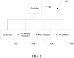
- mass spectrometry platform 100 can include components as displayed in the block diagram of Figure 1 . In various embodiments, elements of Figure 1 can be incorporated into mass spectrometry platform 100. According to various embodiments, mass spectrometer 100 can include an ion source 102, an ion mobility separator 104 , a mass analyzer 106, an ion detector 108, and a controller 110.
- the ion source 102 generates a plurality of ions from a sample.
- the ion source can include, but is not limited to, a matrix assisted laser desorption/ionization (MALDI) source, electrospray ionization (ESI) source, atmospheric pressure chemical ionization (APCI) source, atmospheric pressure photoionization source (APPI), inductively coupled plasma (ICP) source, electron ionization source, chemical ionization source, photoionization source, glow discharge ionization source, thermospray ionization source, and the like.
- MALDI matrix assisted laser desorption/ionization
- ESI electrospray ionization
- APCI atmospheric pressure chemical ionization
- APPI atmospheric pressure photoionization source
- ICP inductively coupled plasma
- the ion mobility separator 104 can separate ions based on an ion mobility within a gas.
- the ion mobility separator 104 can be a drift tube, a traveling wave IMS, a TIMS, field asymmetric ion mobility spectrometer (FAIMS), and the like.
- the ion mobility separator can receive ions from the ion source 102 and provide an additional dimension of separator prior to the mass analyzer 106.
- the mass analyzer 106 can separate ions based on a mass-to-charge ratio of the ions.
- the mass analyzer 106 can include a quadrupole mass filter analyzer, a quadrupole ion trap analyzer, a time-of-flight (TOF) analyzer, an electrostatic trap (e.g., Orbitrap) mass analyzer, Fourier transform ion cyclotron resonance (FT-ICR) mass analyzer, and the like.
- the mass analyzer 106 can also be configured to fragment the ions using collision induced dissociation (CID) electron transfer dissociation (ETD), electron capture dissociation (ECD), photo induced dissociation (PID), surface induced dissociation (SID), and the like, and further separate the fragmented ions based on the mass-to-charge ratio.
- the mass analyzer 106 can be a hybrid system incorporating one or more mass analyzers and mass separators coupled by various combinations of ion optics and storage devices.
- a hybrid system can a linear ion trap (LIT), a high energy collision dissociation device (HCD), an ion transport system, and a TOF.
- the ion detector 108 can detect ions.
- the ion detector 108 can include an electron multiplier, a Faraday cup, and the like. Ions leaving the mass analyzer can be detected by the ion detector.
- the ion detector can be quantitative, such that an accurate count of the ions can be determined.
- the mass analyzer detects the ions, combining the properties of both the mass analyzer 106 and the ion detector 108 into one device.
- the controller 110 can communicate with the ion source 102, the ion mobility separator 104, the mass analyzer 106, and the ion detector 108.
- the controller 110 can configure the ion source 102 or enable/disable the ion source 102.
- the controller 110 can configure the ion mobility separator 104 to select a particular range of ion mobilities.
- the controller 110 can configure the mass analyzer 106 to select a particular mass range to detect.
- the controller 110 can adjust the sensitivity of the ion detector 108, such as by adjusting the gain.
- the controller 110 can adjust the polarity of the ion detector 108 based on the polarity of the ions being detected.
- the ion detector 108 can be configured to detect positive ions or be configured to detected negative ions.
- Trapped ion mobility spectrometry inverts the separation principle of classical drift tube ion mobility. Ions entering the TIMS device are positioned in an electric field by the drag of a gas flow. The ions become trapped at an equilibrium position where the force of the electric field and the force of the drag of the gas flow are balanced. In TIMS, ions are held stationary (or trapped) in a flowing buffer gas by an axial electric field gradient (EFG) profile while the application of radio frequency (rf) potentials results in trapping in the radial dimension.
- EFG axial electric field gradient
- rf radio frequency
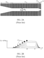
- FIG. 2A shows a closed quadrupole device (11), vertically sliced into thin electrodes forming a circular tube arranged around the z-axis of the device. The electrode slices are separated by insulating material closing the gaps between the electrodes around the tube to make the tube gas-tight.
- the differential pumping system of a mass spectrometer (not shown), surrounding the ion mobility spectrometer, is dimensioned to cause a gas to flow through the tube in a positive x direction. Ions entering the first part (10) of the funnel together with the gas are collisionally focused onto the axis of the tube (11) and move, driven by the gas, along the axis of the tube towards its exit through the apertured diaphragm (13). Most of the gas escapes through gaps between the electrodes of the funnel part (12).
- the operation of the device starts with a filling process.
- the ions (27) are blown by the gas flow against the field barrier and are stopped because they cannot surmount the field barrier.
- Ions with high mobility (small cross section) gather at the foot of the barrier, ions with low mobility gather (large cross section) near the summit, as symbolically indicated by the size of the dots for the ions (27).
- the potential profile (22) is smoothly lowered by decreasing the voltage continuously in a procedure denominated as a "scan" (28), passing through profile states (23) to (26).
- ions of higher and higher mobilities can surmount the decreasing summit of the barrier and exit the ion mobility spectrometer.
- a characteristic feature of this instrument is the long increasing part of the electric field barrier until position (20), the start of the plateau. This long ascent between foot and top of the barrier collects the ions (27) in a rather large volume along the z-axis, reducing greatly any space charge effects.
- Figure 3A illustrates ions trapped in a TIMS device 300.
- the TIMS device 300 has a constant electric field 302 and a gas flow 304 directed in the negative x direction.
- the constant electric field 302 of magnitude E m1 along the length of the TIMS device 300 and the gas flow 304 directed in a negative x direction, low mobility ions 306, medium mobility ions 308, and high mobility ions 310 can be separated with increasing ion mobility in the positive x direction.
- K ( m ) can be changed as a function of position within the TIMS device by varying the cross-section as a function of position S ( x ).
- separating of ions as a function of ion mobility can be accomplished by having a largest cross section near an first end and decreasing the cross section as the ion nears the second end.
- K ( m ) can be changed as a function of position within the TIMS device with a constant cross-section S by varying the mass flow Q ( x ) .
- Q(x) ⁇ (x) * ⁇ g (x) *S.
- the gas velocity can change with the mass flow of the TIMS device. That is, the gas velocity decreases with decreasing mass flow within the TIMS device.
- the gas flow can decrease along the direction of gas flow by providing flow paths out of TIMS device.
- a gas flow can be supplied near an ion exit end with flow paths out of the device along the length so that the lowest mass flow is near the first end and the highest mass flow is near the second end.
- the ions can be released from the device by increasing the electric field to a second magnitude E m2 to increase the ion velocity while the gas flow remains the same. All target ions can exit the TIMS device provided the electric field is high enough that the velocity is positive for all target ions for the length of the device.
- Figure 3B illustrates ions exiting the TIMS device 300 after the electric field 302 is increased from E m1 to E m2 .
- the high mobility ions 310 can exit the TIMS device first, followed by the medium mobility ions 308 and then the low mobility ions 306.
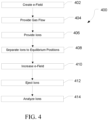
- Figure 4 illustrates a method 400 of operating an ion mobility separator.
- an electric field can be created within the ion mobility separator.
- the electric field can be generated by applying an electrical (DC) potential to electrode along the length of the ion mobility separator.
- the electric field can be constant along the length of the ion mobility separator and can be set to a first magnitude E m1 during a trapping and equilibration time period.
- a gas flow can be provided near a second end of the ion mobility separator.
- the gas flow entering the ion mobility separator can be constant throughout the operation of the ion mobility separator.
- ions from a plurality of analytes can be introduced into the TIMS device near a first end.
- the ions can have a range of ion mobilities, such as depending on the identity of the analyte.
- the ions can be separated according to ion mobility.
- the position dependence can be accomplished by a change in cross section along the length of the ion mobility separator, such that near the first end has a larger cross section than near the second end.
- the position dependence can be accomplished by varying the mass flow within the ion mobility separator, such as by providing gas flow paths for gas to escape along the length of the TIMS device.
- the ions can be separated such that low mobility ions are closer to the first end and high mobility ions are closer to the second end.
- the electric field can be increased, and at 412 the ions can be ejected from the TIMS device.
- the high mobility ions can be ejected first due to their proximity to the second end, while ions of decreasing ion mobility follow.
- the ions can be analyzed, such as by using a mass spectrometer.
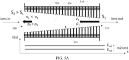
- FIGs 5A and 5B illustrate examples, which are not according to the invention, of an ion mobility separator 500 with a variable cross section.
- ion mobility separator 500 can include a plurality of electrodes 502, such as ring electrodes, arranged along an axis 504.
- Ion mobility separator 500 can have a first end 508 and a second end 512.
- the electrodes 502 can be arranged such that a channel 514 is formed with a cross-section (S) that decreases from the first end to the second end (positive X direction).
- An electric potential can be applied to the electrodes 502 to create a uniform electric field.
- the electric field can push ions in the positive X direction from the first end 508 to the second end 512.
- a gas flow 516 can be supplied at the second end and flow in the direction of the first end (negative X direction). Due to the geometry of the ion mobility separator 500 and the change in cross section, the velocity of the gas can decrease as the gas moves from the second (narrow) end to the first (wide) end, resulting in a variable drag force along the ion mobility separator 500, with a lower drag force at the first end and a high drag force at the second end.
- the electric field can be set at a second magnitude E m2 such v(x)>0 throughout the ion mobility separator for all target ions. This can drive the ions of interest through the second end 512 while maintaining the separation based on ion mobility.
- the electric field can be ramped through a least a portion of the difference between the first magnitude E m1 to the second magnitude E m2 .
- the electric field can jump from E m1 to a level slightly below the level corresponding to the highest ion mobility ions of interest and then ramped through the range of ion mobilities of interest to E m2 .
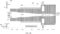
- Figure 5B illustrates the ion mobility separator 500 in the context of the broader system 550.
- Sample can be introduced through capillary 552 and ions can be formed.
- the ions can be drawn into the device using an electric field in area 0.
- Area 0 has an open geometry with a constant cross section to accept ions.
- the ions can then move to an ion funnel in area A to focus the ions.
- Area B has a constant cross section before entering the ion mobility separator 500 in area C.
- the ions After the ions have been separated based on the mobility of the ions, they pass through areas D, E and F before additional focusing in a second ion funnel of area G. After exiting area G, ions can proceed to a mass analyzer for further analysis.
- the gas flow can be introduced in area E.
- the bulk of the gas flow can flow through the areas D, C, B, A, and 0 until it is removed from the system by pumping port 554.
- FIG. 6 illustrates an example of an ion mobility separator 600 not according to the invention with a constant cross section and a variable mass flow.
- Ion mobility separator 600 can include a plurality of electrodes 602, such as ring electrodes, arranged along an axis 604.
- Ion mobility separator 600 can have an ion entrance 608 and an ion exit 610.
- the electrodes 602 can be arranged such that a channel 614 is formed with a constant cross-section (S).
- An electric potential can be applied to the electrodes 602 to create a uniform electric field.
- the electric field can push ions in the positive X direction from the ion entrance 606 to the ion exit 610.
- a gas flow 616 can be supplied near a second end 612 of a mobility separation region 620 and flow in the direction of the first end 608 of the mobility separation region 620 (negative X direction).
- Gas flow paths 618 can be provided within a mobility separation region 620, such as between electrodes 602, so that a portion of gas flow 616 can exit the ion mobility separator 600.
- the electrodes can be uniform and have a similar length or outer diameter to provide gas flow paths 618 of similar length.
- the similar length of gas flow paths 618 can provide similar restriction on the gas flow.
- the decrease in mass flow in the negative x direction due to the loss of a portion of the gas can result in a variable drag force along the ion mobility separator 600, with a lower drag force at the first end and a high drag force at the second end.
- the electric field can be set at a second magnitude E m2 such v(x)>0 throughout the ion mobility separator for all target ions. This can drive the ions through the second end 612 while maintaining the separation based on ion mobility.
- the electric field can be ramped through a least a portion of the difference between the first magnitude E m1 to the second magnitude E m2 .
- the electric field can jump from E m1 to a level slightly below the level corresponding to the highest ion mobility ions of interest and then ramped through the range of ion mobilities of interest to E m2 .
- FIG. 7 illustrates an embodiment of the invention of an ion mobility separator 700 with a constant cross section and a variable mass flow.
- Ion mobility separator 700 can include a plurality of electrodes 702, such as ring electrodes, arranged along an axis 704.
- Ion mobility separator 700 can have an ion entrance 706 and an ion exit 710.
- the electrodes 702 can be arranged such that a channel 714 is formed with a constant cross-section (S).
- An electric potential can be applied to the electrodes 702 to create a uniform electric field.
- the electric field can push ions in the positive X direction from the ion entrance 706 to the ion exit 710.
- a gas flow 716 can be supplied near a second end 712 of an ion mobility separation region 720 and flow in the direction of the first end 708 of the ion mobility separation region 720 (negative X direction).
- Gas flow paths 718 can be provided within the ion mobility separation region 720, such as between electrodes 702, so that a portion of gas flow 716 can exit the ion mobility separator 700.
- the electrodes can have variable lengths or outer diameters to provide gas flow paths 718 of different length.
- the different lengths of gas flow paths 718 can provide varying restriction on the gas flow.
- the decrease in mass flow in the negative x direction due to the loss of a portion of the gas can result in a variable drag force along the ion mobility separator 700, with a lower drag force at the first end and a high drag force at the second end.
- the restriction on the flow paths in Figure 7 vary along the length of the TIMS device, with a higher restriction near the second end 712 with the higher pressure. Since the amount of gas flow out through each flow path is a function of both pressure and restriction, the mass flow profile can be adjusted by varying the length/outer diameter of the electrodes.
- the electric field can be set at a second magnitude E m2 such v(x)>0 throughout the ion mobility separator for all target ions. This can drive the ions through the second end 712 while maintaining the separation based on ion mobility.
- the electric field can be ramped through a least a portion of the difference between the first magnitude E m1 to the second magnitude E m2 .
- the electric field can jump from E m1 to a level slightly below the level corresponding to the highest ion mobility ions of interest and then ramped through the range of ion mobilities of interest to E m2 .
Landscapes
- Chemical & Material Sciences (AREA)
- Physics & Mathematics (AREA)
- Analytical Chemistry (AREA)
- Health & Medical Sciences (AREA)
- Spectroscopy & Molecular Physics (AREA)
- Chemical Kinetics & Catalysis (AREA)
- Electrochemistry (AREA)
- Life Sciences & Earth Sciences (AREA)
- Biochemistry (AREA)
- General Health & Medical Sciences (AREA)
- General Physics & Mathematics (AREA)
- Immunology (AREA)
- Pathology (AREA)
- Plasma & Fusion (AREA)
- Engineering & Computer Science (AREA)
- Other Investigation Or Analysis Of Materials By Electrical Means (AREA)
Claims (6)
- lonenmobilitätsvorrichtung (700), die ein erstes Ende zum Empfangen von Ionen und ein zweites Ende zum Ausstoßen von Ionen aufweist, die lonenmobilitätsvorrichtung umfassend:eine Vielzahl von Elektroden (702), die entlang einer Achse (704) angeordnet sind, wobei sich die Achse von dem ersten Ende zu dem zweiten Ende erstreckt, die Vielzahl von Elektroden konfiguriert ist, um eine Gasströmung in der Nähe des zweiten Endes zu empfangen, wobei die Vielzahl von Elektroden einen Kanal (714) mit gleichmäßigem Querschnitt bildet;eine Stromquelle, die konfiguriert ist zum:Anlegen eines ersten Potentials (Em1) an die Vielzahl von Elektroden, um ein erstes elektrisches Feld während einer Einfangs- und Gleichgewichtszeitspanne zu erzeugen, wobei das erste elektrische Feld entlang der Länge der Achse gleichmäßig ist;Anlegen eines zweiten Potentials (Em2) an die Elektroden während einer Ausstoßzeitspanne, um ein zweites elektrisches Feld zu erzeugen, wobei das zweite elektrische Feld entlang der Länge der Achse von dem ersten Ende zu dem zweiten Ende gleichmäßig ist und größer als das erste elektrische Feld ist;derart, dass, in Verwendung, während der Einfangs- und Gleichgewichtszeitspanne, Ionen entlang der Achse basierend auf ihrer lonenmobilität in Gleichgewichtspositionen getrennt werden, in denen die Kraft, die durch das elektrische Feld angelegt wird, die Widerstandskraft, die durch die Gasströmung angelegt wird, ausgleicht; undwährend der Ausstoßzeitspanne Ionen durch das zweite elektrische Feld aus dem zweiten Ende derart ausgetrieben werden, dass die Trennung, die während der Einfangs- und Gleichgewichtszeitspanne erreicht wird, aufrechterhalten wird,dadurch gekennzeichnet, dassmindestens eine Teilmenge der Vielzahl von Elektroden Strömungswege (718) für die Gasströmung von dem Kanal weg erstellen und wobei die Elektroden in Länge oder Außendurchmesser variieren, um Strömungswege (718) mit variierender Einschränkung der Gasströmung bereitzustellen, um für eine Ausdehnung der Gasströmung von dem zweiten Ende zu dem ersten Ende derart vorzusorgen, dass eine erste Gasgeschwindigkeit an dem zweiten Ende größer ist als eine zweite Gasgeschwindigkeit an dem ersten Ende.
- lonenmobilitätsvorrichtung nach Anspruch 1, wobei die Gasströmung während der Einfangs- und Gleichgewichtszeitspanne und der Ausstoßzeitspanne konstant ist.
- Massenspektrometer, umfassend:eine lonenquelle, die konfiguriert ist, um eine Probe zu ionisieren, um Ionen herzustellen;eine lonenmobilitätsvorrichtung nach einem der vorstehenden Ansprüche; undeinen Massenanalysator, der konfiguriert ist, um die Ionen zu analysieren.
- Verfahren, umfassend:Bereitstellen von Ionen an ein erstes Ende einer lonenmobilitätsvorrichtung (700), wobei die lonenmobilitätsvorrichtung eine Vielzahl von Elektroden (702) einschließt, die entlang einer Achse (704) angeordnet sind, wobei sich die Achse von einem ersten Ende zu einem zweiten Ende erstreckt;Bereitstellen einer Gasströmung in der Nähe des zweiten Endes der lonenmobilitätsvorrichtung, wobei die Vielzahl von Elektroden einen Kanal (714) mit gleichmäßigem Querschnitt bildet;Anlegen eines elektrischen Felds (Em1)mit einer ersten Größe in einer Richtung entgegengesetzt zu der Gasströmung, wobei das elektrische Feld entlang der Achse gleichmäßig ist;Trennen von Ionen in Gleichgewichtspositionen entlang der Achse basierend auf ihrer lonenmobilität, wobei die Gleichgewichtspositionen dort liegen, wo die Kraft, die durch das elektrische Feld angelegt wird, die Widerstandskraft, die durch die Gasströmung angelegt wird, ausgleicht;Ausstoßen von Ionen aus dem zweiten Ende durch Erhöhen des elektrischen Felds auf eine zweite Größe (Em2);dadurch gekennzeichnet, dassmindestens eine Teilmenge der Vielzahl von Elektroden Strömungswege für die Gasströmung von dem Kanal weg erstellen und wobei die Elektroden in Länge oder Außendurchmesser variieren, um Strömungswege (718) mit variierender Einschränkung der Gasströmung bereitzustellen, um für eine Ausdehnung der Gasströmung von dem zweiten Ende zu dem ersten Ende derart vorzusorgen, dass eine erste Gasgeschwindigkeit an dem zweiten Ende größer ist als eine zweite Gasgeschwindigkeit an dem ersten Ende.
- Verfahren nach Anspruch 4, ferner umfassend das Ionisieren einer Probe, um die Ionen herzustellen.
- Verfahren nach Anspruch 4 oder 5, ferner umfassend das Analysieren der Ionen, nachdem die Ionen ausgestoßen werden.
Priority Applications (1)
| Application Number | Priority Date | Filing Date | Title |
|---|---|---|---|
| EP24179261.3A EP4404239A3 (de) | 2020-04-03 | 2021-03-30 | Gleichstromionenmobilitätsspektrometer mit gleichmässigem feld |
Applications Claiming Priority (1)
| Application Number | Priority Date | Filing Date | Title |
|---|---|---|---|
| US16/840,044 US11099153B1 (en) | 2020-04-03 | 2020-04-03 | Counterflow uniform-field ion mobility spectrometer |
Related Child Applications (2)
| Application Number | Title | Priority Date | Filing Date |
|---|---|---|---|
| EP24179261.3A Division EP4404239A3 (de) | 2020-04-03 | 2021-03-30 | Gleichstromionenmobilitätsspektrometer mit gleichmässigem feld |
| EP24179261.3A Division-Into EP4404239A3 (de) | 2020-04-03 | 2021-03-30 | Gleichstromionenmobilitätsspektrometer mit gleichmässigem feld |
Publications (2)
| Publication Number | Publication Date |
|---|---|
| EP3889595A1 EP3889595A1 (de) | 2021-10-06 |
| EP3889595B1 true EP3889595B1 (de) | 2024-07-17 |
Family
ID=75302299
Family Applications (2)
| Application Number | Title | Priority Date | Filing Date |
|---|---|---|---|
| EP24179261.3A Pending EP4404239A3 (de) | 2020-04-03 | 2021-03-30 | Gleichstromionenmobilitätsspektrometer mit gleichmässigem feld |
| EP21165873.7A Active EP3889595B1 (de) | 2020-04-03 | 2021-03-30 | Gegenstrom-gleichfeld-ionenmobilitätsspektrometer |
Family Applications Before (1)
| Application Number | Title | Priority Date | Filing Date |
|---|---|---|---|
| EP24179261.3A Pending EP4404239A3 (de) | 2020-04-03 | 2021-03-30 | Gleichstromionenmobilitätsspektrometer mit gleichmässigem feld |
Country Status (3)
| Country | Link |
|---|---|
| US (1) | US11099153B1 (de) |
| EP (2) | EP4404239A3 (de) |
| CN (1) | CN113496866B (de) |
Families Citing this family (1)
| Publication number | Priority date | Publication date | Assignee | Title |
|---|---|---|---|---|
| US12176196B2 (en) * | 2019-02-15 | 2024-12-24 | Ohio State Innovation Foundation | Surface-induced dissociation devices and methods |
Family Cites Families (15)
| Publication number | Priority date | Publication date | Assignee | Title |
|---|---|---|---|---|
| US6630662B1 (en) | 2002-04-24 | 2003-10-07 | Mds Inc. | Setup for mobility separation of ions implementing an ion guide with an axial field and counterflow of gas |
| EP1614141A4 (de) | 2003-04-09 | 2007-09-12 | Univ Brigham Young | Querströmungsionenmobilitätsanalysator |
| DE102007017055B4 (de) * | 2007-04-11 | 2011-06-22 | Bruker Daltonik GmbH, 28359 | Messung der Mobilität massenselektierter Ionen |
| JP4862738B2 (ja) | 2007-05-08 | 2012-01-25 | 株式会社日立製作所 | イオン移動度分析装置およびイオン移動度分離/質量分析複合装置 |
| US7838826B1 (en) | 2008-08-07 | 2010-11-23 | Bruker Daltonics, Inc. | Apparatus and method for parallel flow ion mobility spectrometry combined with mass spectrometry |
| GB0817433D0 (en) | 2008-09-23 | 2008-10-29 | Thermo Fisher Scient Bremen | Ion trap for cooling ions |
| CN101738429B (zh) | 2008-11-26 | 2013-04-03 | 岛津分析技术研发(上海)有限公司 | 离子分离、富集与检测装置 |
| US8624180B2 (en) * | 2011-04-26 | 2014-01-07 | Bruker Daltonik Gmbh | Resolution enhancement for ion mobility spectrometers |
| US8941054B2 (en) * | 2011-04-26 | 2015-01-27 | Bruker Daltonik Gmbh | Selective ion mobility spectrometer formed from two consecutive mass selective filters |
| CN103515183B (zh) * | 2012-06-20 | 2017-06-23 | 株式会社岛津制作所 | 离子导引装置和离子导引方法 |
| GB201323004D0 (en) | 2013-12-24 | 2014-02-12 | Micromass Ltd | Travelling wave IMS with counterflow of gas |
| CN105702555A (zh) * | 2014-11-27 | 2016-06-22 | 中国科学院大连化学物理研究所 | 一种增强差分离子迁移谱电离效率的方法 |
| US9304106B1 (en) | 2015-02-05 | 2016-04-05 | Bruker Daltonik Gmbh | High duty cycle trapping ion mobility spectrometer |
| CN109003876B (zh) * | 2017-06-06 | 2020-10-16 | 岛津分析技术研发(上海)有限公司 | 离子迁移率分析器及分析方法 |
| US11275054B2 (en) * | 2018-02-13 | 2022-03-15 | Jp Scientific Limited | Ion mobility spectrometer and method of analyzing ions |
-
2020
- 2020-04-03 US US16/840,044 patent/US11099153B1/en active Active
-
2021
- 2021-03-30 EP EP24179261.3A patent/EP4404239A3/de active Pending
- 2021-03-30 EP EP21165873.7A patent/EP3889595B1/de active Active
- 2021-04-01 CN CN202110356412.9A patent/CN113496866B/zh active Active
Also Published As
| Publication number | Publication date |
|---|---|
| US11099153B1 (en) | 2021-08-24 |
| EP4404239A3 (de) | 2024-08-28 |
| EP3889595A1 (de) | 2021-10-06 |
| CN113496866A (zh) | 2021-10-12 |
| CN113496866B (zh) | 2022-08-16 |
| EP4404239A2 (de) | 2024-07-24 |
Similar Documents
| Publication | Publication Date | Title |
|---|---|---|
| EP2926125B1 (de) | Vorrichtung und verfahren für querlaufende ionenmobilitätsspektrometrie | |
| US9753011B2 (en) | Apparatus and methods for ion mobility spectrometry | |
| EP2637018B1 (de) | Asymmetrische Feldionenmobilität in einer Ionenfalle mit linearer Geometrie | |
| EP2795661B1 (de) | Ionenmobilitätstrennvorrichtung mit beweglicher ausgangsöffnung | |
| EP2309531A1 (de) | Massenanalysator | |
| US11488815B2 (en) | Trap fill time dynamic range enhancment | |
| GB2436004A (en) | Molecular activation of analyte ions in a tandem mass spectrometer | |
| US11270877B2 (en) | Multipole ion guide | |
| EP1760764B1 (de) | Linsenvorrichtung um einen zweiten Ionenstrahl in einen Primärionenstrahl einzufügen | |
| US20170212081A1 (en) | Mobility Selective Attenuation | |
| CN107437491B (zh) | 用于减少从线性离子阱径向射出的离子的动能扩散的系统和方法 | |
| CN109791125B (zh) | 分离后迁移率分析器及用于确定离子碰撞截面的方法 | |
| US11031232B1 (en) | Injection of ions into an ion storage device | |
| US7166836B1 (en) | Ion beam focusing device | |
| EP3889595B1 (de) | Gegenstrom-gleichfeld-ionenmobilitätsspektrometer | |
| US12500074B2 (en) | Characterizing quadrupole transmitting window in mass spectrometers | |
| US20220057363A1 (en) | Ion mobility separation system with rotating field confinement | |
| CN119495550A (zh) | 离子迁移率-质荷比数据的采集 | |
| US20250003924A1 (en) | Differential trapped ion mobility filter | |
| US20250069877A1 (en) | Method to Operate a Mass Spectrometer to Counteract Space Charge Effects | |
| US20250003923A1 (en) | Differential trapped ion mobility separator | |
| HK40114920A (zh) | 差分捕获离子迁移率过滤器 | |
| HK40114921A (zh) | 差分捕集离子淌度分离器 |
Legal Events
| Date | Code | Title | Description |
|---|---|---|---|
| PUAI | Public reference made under article 153(3) epc to a published international application that has entered the european phase |
Free format text: ORIGINAL CODE: 0009012 |
|
| STAA | Information on the status of an ep patent application or granted ep patent |
Free format text: STATUS: THE APPLICATION HAS BEEN PUBLISHED |
|
| AK | Designated contracting states |
Kind code of ref document: A1 Designated state(s): AL AT BE BG CH CY CZ DE DK EE ES FI FR GB GR HR HU IE IS IT LI LT LU LV MC MK MT NL NO PL PT RO RS SE SI SK SM TR |
|
| STAA | Information on the status of an ep patent application or granted ep patent |
Free format text: STATUS: REQUEST FOR EXAMINATION WAS MADE |
|
| 17P | Request for examination filed |
Effective date: 20220325 |
|
| RBV | Designated contracting states (corrected) |
Designated state(s): AL AT BE BG CH CY CZ DE DK EE ES FI FR GB GR HR HU IE IS IT LI LT LU LV MC MK MT NL NO PL PT RO RS SE SI SK SM TR |
|
| GRAP | Despatch of communication of intention to grant a patent |
Free format text: ORIGINAL CODE: EPIDOSNIGR1 |
|
| STAA | Information on the status of an ep patent application or granted ep patent |
Free format text: STATUS: GRANT OF PATENT IS INTENDED |
|
| INTG | Intention to grant announced |
Effective date: 20240214 |
|
| GRAS | Grant fee paid |
Free format text: ORIGINAL CODE: EPIDOSNIGR3 |
|
| GRAA | (expected) grant |
Free format text: ORIGINAL CODE: 0009210 |
|
| STAA | Information on the status of an ep patent application or granted ep patent |
Free format text: STATUS: THE PATENT HAS BEEN GRANTED |
|
| AK | Designated contracting states |
Kind code of ref document: B1 Designated state(s): AL AT BE BG CH CY CZ DE DK EE ES FI FR GB GR HR HU IE IS IT LI LT LU LV MC MK MT NL NO PL PT RO RS SE SI SK SM TR |
|
| REG | Reference to a national code |
Ref country code: CH Ref legal event code: EP |
|
| REG | Reference to a national code |
Ref country code: DE Ref legal event code: R096 Ref document number: 602021015677 Country of ref document: DE |
|
| REG | Reference to a national code |
Ref country code: IE Ref legal event code: FG4D |
|
| REG | Reference to a national code |
Ref country code: LT Ref legal event code: MG9D |
|
| REG | Reference to a national code |
Ref country code: NL Ref legal event code: MP Effective date: 20240717 |
|
| PG25 | Lapsed in a contracting state [announced via postgrant information from national office to epo] |
Ref country code: PT Free format text: LAPSE BECAUSE OF FAILURE TO SUBMIT A TRANSLATION OF THE DESCRIPTION OR TO PAY THE FEE WITHIN THE PRESCRIBED TIME-LIMIT Effective date: 20241118 |
|
| REG | Reference to a national code |
Ref country code: AT Ref legal event code: MK05 Ref document number: 1704592 Country of ref document: AT Kind code of ref document: T Effective date: 20240717 |
|
| PG25 | Lapsed in a contracting state [announced via postgrant information from national office to epo] |
Ref country code: NL Free format text: LAPSE BECAUSE OF FAILURE TO SUBMIT A TRANSLATION OF THE DESCRIPTION OR TO PAY THE FEE WITHIN THE PRESCRIBED TIME-LIMIT Effective date: 20240717 |
|
| PG25 | Lapsed in a contracting state [announced via postgrant information from national office to epo] |
Ref country code: PT Free format text: LAPSE BECAUSE OF FAILURE TO SUBMIT A TRANSLATION OF THE DESCRIPTION OR TO PAY THE FEE WITHIN THE PRESCRIBED TIME-LIMIT Effective date: 20241118 Ref country code: NL Free format text: LAPSE BECAUSE OF FAILURE TO SUBMIT A TRANSLATION OF THE DESCRIPTION OR TO PAY THE FEE WITHIN THE PRESCRIBED TIME-LIMIT Effective date: 20240717 |
|
| PG25 | Lapsed in a contracting state [announced via postgrant information from national office to epo] |
Ref country code: NO Free format text: LAPSE BECAUSE OF FAILURE TO SUBMIT A TRANSLATION OF THE DESCRIPTION OR TO PAY THE FEE WITHIN THE PRESCRIBED TIME-LIMIT Effective date: 20241017 |
|
| PG25 | Lapsed in a contracting state [announced via postgrant information from national office to epo] |
Ref country code: GR Free format text: LAPSE BECAUSE OF FAILURE TO SUBMIT A TRANSLATION OF THE DESCRIPTION OR TO PAY THE FEE WITHIN THE PRESCRIBED TIME-LIMIT Effective date: 20241018 Ref country code: FI Free format text: LAPSE BECAUSE OF FAILURE TO SUBMIT A TRANSLATION OF THE DESCRIPTION OR TO PAY THE FEE WITHIN THE PRESCRIBED TIME-LIMIT Effective date: 20240717 Ref country code: PL Free format text: LAPSE BECAUSE OF FAILURE TO SUBMIT A TRANSLATION OF THE DESCRIPTION OR TO PAY THE FEE WITHIN THE PRESCRIBED TIME-LIMIT Effective date: 20240717 |
|
| PG25 | Lapsed in a contracting state [announced via postgrant information from national office to epo] |
Ref country code: BG Free format text: LAPSE BECAUSE OF FAILURE TO SUBMIT A TRANSLATION OF THE DESCRIPTION OR TO PAY THE FEE WITHIN THE PRESCRIBED TIME-LIMIT Effective date: 20240717 |
|
| PG25 | Lapsed in a contracting state [announced via postgrant information from national office to epo] |
Ref country code: LV Free format text: LAPSE BECAUSE OF FAILURE TO SUBMIT A TRANSLATION OF THE DESCRIPTION OR TO PAY THE FEE WITHIN THE PRESCRIBED TIME-LIMIT Effective date: 20240717 |
|
| PG25 | Lapsed in a contracting state [announced via postgrant information from national office to epo] |
Ref country code: IS Free format text: LAPSE BECAUSE OF FAILURE TO SUBMIT A TRANSLATION OF THE DESCRIPTION OR TO PAY THE FEE WITHIN THE PRESCRIBED TIME-LIMIT Effective date: 20241117 Ref country code: AT Free format text: LAPSE BECAUSE OF FAILURE TO SUBMIT A TRANSLATION OF THE DESCRIPTION OR TO PAY THE FEE WITHIN THE PRESCRIBED TIME-LIMIT Effective date: 20240717 |
|
| PG25 | Lapsed in a contracting state [announced via postgrant information from national office to epo] |
Ref country code: HR Free format text: LAPSE BECAUSE OF FAILURE TO SUBMIT A TRANSLATION OF THE DESCRIPTION OR TO PAY THE FEE WITHIN THE PRESCRIBED TIME-LIMIT Effective date: 20240717 |
|
| PG25 | Lapsed in a contracting state [announced via postgrant information from national office to epo] |
Ref country code: ES Free format text: LAPSE BECAUSE OF FAILURE TO SUBMIT A TRANSLATION OF THE DESCRIPTION OR TO PAY THE FEE WITHIN THE PRESCRIBED TIME-LIMIT Effective date: 20240717 Ref country code: RS Free format text: LAPSE BECAUSE OF FAILURE TO SUBMIT A TRANSLATION OF THE DESCRIPTION OR TO PAY THE FEE WITHIN THE PRESCRIBED TIME-LIMIT Effective date: 20241017 |
|
| PG25 | Lapsed in a contracting state [announced via postgrant information from national office to epo] |
Ref country code: RS Free format text: LAPSE BECAUSE OF FAILURE TO SUBMIT A TRANSLATION OF THE DESCRIPTION OR TO PAY THE FEE WITHIN THE PRESCRIBED TIME-LIMIT Effective date: 20241017 Ref country code: PL Free format text: LAPSE BECAUSE OF FAILURE TO SUBMIT A TRANSLATION OF THE DESCRIPTION OR TO PAY THE FEE WITHIN THE PRESCRIBED TIME-LIMIT Effective date: 20240717 Ref country code: NO Free format text: LAPSE BECAUSE OF FAILURE TO SUBMIT A TRANSLATION OF THE DESCRIPTION OR TO PAY THE FEE WITHIN THE PRESCRIBED TIME-LIMIT Effective date: 20241017 Ref country code: LV Free format text: LAPSE BECAUSE OF FAILURE TO SUBMIT A TRANSLATION OF THE DESCRIPTION OR TO PAY THE FEE WITHIN THE PRESCRIBED TIME-LIMIT Effective date: 20240717 Ref country code: IS Free format text: LAPSE BECAUSE OF FAILURE TO SUBMIT A TRANSLATION OF THE DESCRIPTION OR TO PAY THE FEE WITHIN THE PRESCRIBED TIME-LIMIT Effective date: 20241117 Ref country code: HR Free format text: LAPSE BECAUSE OF FAILURE TO SUBMIT A TRANSLATION OF THE DESCRIPTION OR TO PAY THE FEE WITHIN THE PRESCRIBED TIME-LIMIT Effective date: 20240717 Ref country code: GR Free format text: LAPSE BECAUSE OF FAILURE TO SUBMIT A TRANSLATION OF THE DESCRIPTION OR TO PAY THE FEE WITHIN THE PRESCRIBED TIME-LIMIT Effective date: 20241018 Ref country code: FI Free format text: LAPSE BECAUSE OF FAILURE TO SUBMIT A TRANSLATION OF THE DESCRIPTION OR TO PAY THE FEE WITHIN THE PRESCRIBED TIME-LIMIT Effective date: 20240717 Ref country code: ES Free format text: LAPSE BECAUSE OF FAILURE TO SUBMIT A TRANSLATION OF THE DESCRIPTION OR TO PAY THE FEE WITHIN THE PRESCRIBED TIME-LIMIT Effective date: 20240717 Ref country code: BG Free format text: LAPSE BECAUSE OF FAILURE TO SUBMIT A TRANSLATION OF THE DESCRIPTION OR TO PAY THE FEE WITHIN THE PRESCRIBED TIME-LIMIT Effective date: 20240717 Ref country code: AT Free format text: LAPSE BECAUSE OF FAILURE TO SUBMIT A TRANSLATION OF THE DESCRIPTION OR TO PAY THE FEE WITHIN THE PRESCRIBED TIME-LIMIT Effective date: 20240717 |
|
| PGFP | Annual fee paid to national office [announced via postgrant information from national office to epo] |
Ref country code: DE Payment date: 20250220 Year of fee payment: 5 |
|
| PG25 | Lapsed in a contracting state [announced via postgrant information from national office to epo] |
Ref country code: DK Free format text: LAPSE BECAUSE OF FAILURE TO SUBMIT A TRANSLATION OF THE DESCRIPTION OR TO PAY THE FEE WITHIN THE PRESCRIBED TIME-LIMIT Effective date: 20240717 Ref country code: RO Free format text: LAPSE BECAUSE OF FAILURE TO SUBMIT A TRANSLATION OF THE DESCRIPTION OR TO PAY THE FEE WITHIN THE PRESCRIBED TIME-LIMIT Effective date: 20240717 Ref country code: SM Free format text: LAPSE BECAUSE OF FAILURE TO SUBMIT A TRANSLATION OF THE DESCRIPTION OR TO PAY THE FEE WITHIN THE PRESCRIBED TIME-LIMIT Effective date: 20240717 |
|
| REG | Reference to a national code |
Ref country code: DE Ref legal event code: R097 Ref document number: 602021015677 Country of ref document: DE |
|
| PG25 | Lapsed in a contracting state [announced via postgrant information from national office to epo] |
Ref country code: EE Free format text: LAPSE BECAUSE OF FAILURE TO SUBMIT A TRANSLATION OF THE DESCRIPTION OR TO PAY THE FEE WITHIN THE PRESCRIBED TIME-LIMIT Effective date: 20240717 |
|
| PG25 | Lapsed in a contracting state [announced via postgrant information from national office to epo] |
Ref country code: CZ Free format text: LAPSE BECAUSE OF FAILURE TO SUBMIT A TRANSLATION OF THE DESCRIPTION OR TO PAY THE FEE WITHIN THE PRESCRIBED TIME-LIMIT Effective date: 20240717 |
|
| PG25 | Lapsed in a contracting state [announced via postgrant information from national office to epo] |
Ref country code: SK Free format text: LAPSE BECAUSE OF FAILURE TO SUBMIT A TRANSLATION OF THE DESCRIPTION OR TO PAY THE FEE WITHIN THE PRESCRIBED TIME-LIMIT Effective date: 20240717 |
|
| PGFP | Annual fee paid to national office [announced via postgrant information from national office to epo] |
Ref country code: GB Payment date: 20250307 Year of fee payment: 5 |
|
| PLBE | No opposition filed within time limit |
Free format text: ORIGINAL CODE: 0009261 |
|
| STAA | Information on the status of an ep patent application or granted ep patent |
Free format text: STATUS: NO OPPOSITION FILED WITHIN TIME LIMIT |
|
| 26N | No opposition filed |
Effective date: 20250422 |
|
| PG25 | Lapsed in a contracting state [announced via postgrant information from national office to epo] |
Ref country code: SE Free format text: LAPSE BECAUSE OF FAILURE TO SUBMIT A TRANSLATION OF THE DESCRIPTION OR TO PAY THE FEE WITHIN THE PRESCRIBED TIME-LIMIT Effective date: 20240717 |
|
| PG25 | Lapsed in a contracting state [announced via postgrant information from national office to epo] |
Ref country code: MC Free format text: LAPSE BECAUSE OF FAILURE TO SUBMIT A TRANSLATION OF THE DESCRIPTION OR TO PAY THE FEE WITHIN THE PRESCRIBED TIME-LIMIT Effective date: 20240717 |
|
| REG | Reference to a national code |
Ref country code: CH Ref legal event code: H13 Free format text: ST27 STATUS EVENT CODE: U-0-0-H10-H13 (AS PROVIDED BY THE NATIONAL OFFICE) Effective date: 20251023 |
|
| PG25 | Lapsed in a contracting state [announced via postgrant information from national office to epo] |
Ref country code: LU Free format text: LAPSE BECAUSE OF NON-PAYMENT OF DUE FEES Effective date: 20250330 |
|
| REG | Reference to a national code |
Ref country code: BE Ref legal event code: MM Effective date: 20250331 |