EP3889585B1 - Reference cassette for fluorescence immunoassay diagnostic device - Google Patents
Reference cassette for fluorescence immunoassay diagnostic device Download PDFInfo
- Publication number
- EP3889585B1 EP3889585B1 EP19903149.3A EP19903149A EP3889585B1 EP 3889585 B1 EP3889585 B1 EP 3889585B1 EP 19903149 A EP19903149 A EP 19903149A EP 3889585 B1 EP3889585 B1 EP 3889585B1
- Authority
- EP
- European Patent Office
- Prior art keywords
- fluorescence
- glass
- case
- mask
- fluorescence glass
- Prior art date
- Legal status (The legal status is an assumption and is not a legal conclusion. Google has not performed a legal analysis and makes no representation as to the accuracy of the status listed.)
- Active
Links
Images


Classifications
-
- G—PHYSICS
- G01—MEASURING; TESTING
- G01N—INVESTIGATING OR ANALYSING MATERIALS BY DETERMINING THEIR CHEMICAL OR PHYSICAL PROPERTIES
- G01N21/00—Investigating or analysing materials by the use of optical means, i.e. using sub-millimetre waves, infrared, visible or ultraviolet light
- G01N21/62—Systems in which the material investigated is excited whereby it emits light or causes a change in wavelength of the incident light
- G01N21/63—Systems in which the material investigated is excited whereby it emits light or causes a change in wavelength of the incident light optically excited
- G01N21/64—Fluorescence; Phosphorescence
- G01N21/6447—Fluorescence; Phosphorescence by visual observation
-
- G—PHYSICS
- G01—MEASURING; TESTING
- G01N—INVESTIGATING OR ANALYSING MATERIALS BY DETERMINING THEIR CHEMICAL OR PHYSICAL PROPERTIES
- G01N21/00—Investigating or analysing materials by the use of optical means, i.e. using sub-millimetre waves, infrared, visible or ultraviolet light
- G01N21/62—Systems in which the material investigated is excited whereby it emits light or causes a change in wavelength of the incident light
- G01N21/63—Systems in which the material investigated is excited whereby it emits light or causes a change in wavelength of the incident light optically excited
- G01N21/64—Fluorescence; Phosphorescence
- G01N21/645—Specially adapted constructive features of fluorimeters
-
- G—PHYSICS
- G01—MEASURING; TESTING
- G01N—INVESTIGATING OR ANALYSING MATERIALS BY DETERMINING THEIR CHEMICAL OR PHYSICAL PROPERTIES
- G01N21/00—Investigating or analysing materials by the use of optical means, i.e. using sub-millimetre waves, infrared, visible or ultraviolet light
- G01N21/84—Systems specially adapted for particular applications
- G01N21/8483—Investigating reagent band
-
- G—PHYSICS
- G01—MEASURING; TESTING
- G01N—INVESTIGATING OR ANALYSING MATERIALS BY DETERMINING THEIR CHEMICAL OR PHYSICAL PROPERTIES
- G01N33/00—Investigating or analysing materials by specific methods not covered by groups G01N1/00 - G01N31/00
- G01N33/48—Biological material, e.g. blood, urine; Haemocytometers
- G01N33/50—Chemical analysis of biological material, e.g. blood, urine; Testing involving biospecific ligand binding methods; Immunological testing
- G01N33/53—Immunoassay; Biospecific binding assay; Materials therefor
- G01N33/543—Immunoassay; Biospecific binding assay; Materials therefor with an insoluble carrier for immobilising immunochemicals
- G01N33/54366—Apparatus specially adapted for solid-phase testing
- G01N33/54386—Analytical elements
- G01N33/54387—Immunochromatographic test strips
- G01N33/54388—Immunochromatographic test strips based on lateral flow
-
- G—PHYSICS
- G01—MEASURING; TESTING
- G01N—INVESTIGATING OR ANALYSING MATERIALS BY DETERMINING THEIR CHEMICAL OR PHYSICAL PROPERTIES
- G01N21/00—Investigating or analysing materials by the use of optical means, i.e. using sub-millimetre waves, infrared, visible or ultraviolet light
- G01N21/62—Systems in which the material investigated is excited whereby it emits light or causes a change in wavelength of the incident light
- G01N21/63—Systems in which the material investigated is excited whereby it emits light or causes a change in wavelength of the incident light optically excited
- G01N21/64—Fluorescence; Phosphorescence
- G01N21/645—Specially adapted constructive features of fluorimeters
- G01N2021/6482—Sample cells, cuvettes
-
- G—PHYSICS
- G01—MEASURING; TESTING
- G01N—INVESTIGATING OR ANALYSING MATERIALS BY DETERMINING THEIR CHEMICAL OR PHYSICAL PROPERTIES
- G01N21/00—Investigating or analysing materials by the use of optical means, i.e. using sub-millimetre waves, infrared, visible or ultraviolet light
- G01N21/75—Systems in which material is subjected to a chemical reaction, the progress or the result of the reaction being investigated
- G01N21/77—Systems in which material is subjected to a chemical reaction, the progress or the result of the reaction being investigated by observing the effect on a chemical indicator
- G01N2021/7756—Sensor type
- G01N2021/7759—Dipstick; Test strip
-
- G—PHYSICS
- G01—MEASURING; TESTING
- G01N—INVESTIGATING OR ANALYSING MATERIALS BY DETERMINING THEIR CHEMICAL OR PHYSICAL PROPERTIES
- G01N21/00—Investigating or analysing materials by the use of optical means, i.e. using sub-millimetre waves, infrared, visible or ultraviolet light
- G01N21/75—Systems in which material is subjected to a chemical reaction, the progress or the result of the reaction being investigated
- G01N21/77—Systems in which material is subjected to a chemical reaction, the progress or the result of the reaction being investigated by observing the effect on a chemical indicator
- G01N2021/7769—Measurement method of reaction-produced change in sensor
- G01N2021/7786—Fluorescence
Definitions
- the present invention is generally related to a reference cassette for a fluorescence type immunoassay diagnostic apparatus. More specifically, the present invention is related to a reference cassette for a fluorescence type immunoassay diagnostic apparatus in which, by arranging fluorescence glass, which does not change in characteristics and is capable of constantly maintaining fluorescence characteristics, inside a case, in a process of testing measurement accuracy regarding fluorescence detection of the immunoassay diagnostic apparatus, reference measurement information regarding the fluorescence detection can be precisely provided and therefore the accuracy of the test can be improved, because the change in characteristics and heat deterioration of the fluorescence glass do not occur, the measurement accuracy may not be lowered even it is continuously used and it can be used semi-permanently, and by having a mask at which slits limiting an outside exposure area of the fluorescence glass to a specific area are formed, the fluorescence having the same shape as the reaction area of the actually used specimen strip can be generated.
- a test method used in disease diagnosis is based on color development, fluorescence and so on by enzyme reaction, but recently immunoassay using immunization reaction between an antigen and an antibody is also being used.
- immunoassay methods mainly label antibodies with radioisotopes or fluorescent substances to identify the presence or absence of antigens, and label type biosensors are used to quantify the intensity of radiation or fluorescence.
- the immune sensor Because antibodies, which are the target substance of an immune sensor, are present in very low concentrations in biological samples such as whole blood, serum, urine and so on, the immune sensor requires to have a signaling technology which is much more highly sensitive than the biosensor technology of detecting other substances in terms of detection limit of the sensor. In addition, since the structure of protein such as antibodies or protein antigens are easily altered by changes in the external environment, the recognition portion of the antigen or antibody is deteriorated, and thus unique biometric recognition function is easily lost. Because the immune sensor requires to perform analysis in the solid form, the production of a sensor surface suitable for the biopsy materials that can maintain the activation of the biopsy materials, the immobilization technology of the biopsy materials which can increase the detection limit, and the measurement method transforming biometric recognition reaction to quantified signals are needed.
- Rapid diagnostic test kits for immunoassay are test instruments for point-of-care that is capable of performing diagnostic test using biopsy specimens such as blood, urine, and saliva. Examples of such rapid diagnostic test kits include pregnancy diagnosis kits, AIDS diagnosis kits, and so on.
- Those diagnostic devices require to establish a method capable of detecting biomaterial (protein or DNA, etc.) for diagnosis.
- a fluorescent labeling method using an organic dye or the like has been known as a conventional method for detecting the biomaterial.
- the fluorescent label emits various colors depending on types to provide a detection means for a target biomaterial.
- the immunoassay diagnostic devices use a specimen strip capable of absorbing and supplying biopsy specimen through capillary phenomenon, and a plurality of reaction areas are formed at the specimen strip by applying different reaction material to each of the reaction areas.
- each reactive substance is combined with a biopsy specimen having a specific disease to form a fluorescent reaction complex, and the fluorescent reaction complex generates fluorescence when light is applied.
- the test light is applied to the specimen strip from a light source, and fluorescence generated from the reaction region of the specimen strip is detected by an optical system, thereby diagnosing a specific disease associated with the biopsy specimen.
- a separate reference cassette is used, and the reference cassette is manufactured in a state that a test strip is accommodated therein and a fluorescent substance in an unmodified standard state is applied to the test strip.
- the reference cassette is inserted into the device to apply test light, and fluorescence generated from the fluorescent material of the test strip is detected to check whether a measurement error occurs in the device. That is, if the detection amount of the fluorescence detected by inserting the reference cassette into the device is different from a predetermined standard detection amount, an error occurs in the device, and an error occurrence alarm sign may be output through a display unit of the device.
- the reference cassette for testing the measurement accuracy of the immunoassay diagnostic device requires to be manufactured very precisely, and the fluorescent material applied to the test strip of the reference cassette also needs to be maintained constantly in a standard state in which the characteristics are not changed.
- the fluorescent substance is easily denatured by the external environment due to its characteristics and therefore it is difficult to maintain the characteristics of the standard state, and in this case, the reference cassette cannot perform normal function as the reference cassette for testing the measurement accuracy of the immunoassay diagnostic device.
- WO 2017/199510 A1 discloses a reference body with a support body provided with a first light transmission part, a second light transmission part, a first accommodation space and a second accommodation space; a first fluorescent body that is accommodated in the first accommodation space and emits first fluorescence of a second wavelength band when irradiated via the first light transmission part with first excitation light of a first wavelength band; a second fluorescent body that is accommodated in the second accommodation space and emits second fluorescence of the second wavelength band when irradiated via the second light transmission part with second excitation light of the first wavelength band; and a light blocking part disposed between the first accommodation space and second accommodation space.
- US 2013/230845 A1 discloses a system comprised of an apparatus and a test device.
- the test device and the apparatus are designed to interact to determine the presence or absence of an analyte of interest in a sample placed on the test device.
- the purpose of the present invention may be for providing a reference cassette for a fluorescence type immunoassay diagnostic apparatus in which, by arranging fluorescence glass, which does not change in characteristics and is capable of constantly maintaining fluorescence characteristics, inside a case, in a process of testing measurement accuracy regarding fluorescence detection of the immunoassay diagnostic apparatus, reference measurement information regarding the fluorescence detection can be precisely provided and therefore the accuracy of the test can be improved, because the change in characteristics and heat deterioration of the fluorescence glass do not occur, the measurement accuracy may not be lowered even it is continuously used and it can be used semi-permanently.
- Another purpose of the present invention may be for providing a reference cassette for a fluorescence type immunoassay diagnostic apparatus in which, by having a mask at which slits limiting an outside exposure area of the fluorescence glass to a specific area are formed, the fluorescence having the same shape as the reaction area of the actually used specimen strip can be generated and therefore more accurate reference measurement information can be provided.
- Still another purpose of the present invention may be for providing a reference cassette for a fluorescence type immunoassay diagnostic apparatus in which by guiding the coupling location of the fluorescence glass and the mask, the position of the fluorescence glass and the mask can be precisely maintained and accordingly the test accuracy can be improved.
- Still another purpose of the present invention may be for providing a reference cassette for a fluorescence type immunoassay diagnostic apparatus in which a mask is formed in a metal plate shape and is arranged to contact the upper surface of fluorescence glass and therefore during a process that test light and fluorescence pass through the slit of the mask the influence of the shadow can be minimized and the fluorescence measurement accuracy can be improved.
- the present invention provides a reference cassette in accordance with claim 1.
- a reference cassette for a fluorescence immunoassay diagnostic apparatus which is inserted into the apparatus diagnosing a disease from a biopsy specimen using fluorescence and generates fluorescence by a test light of an optical module
- the reference cassette for the fluorescence immunoassay diagnostic apparatus may comprise: a case configured to be insertable into the fluorescence immunoassay diagnostic apparatus, wherein an opening is formed at at least a part of an upper side of the case so that an inner space of the case is exposed to an outside of the case; and a fluorescence glass disposed at the inner space of the case so that the fluorescence glass is exposed to the outside of the case through the opening of the case, wherein the fluorescence glass is configured to generate the fluorescence by the test light of the optical module and constantly maintain fluorescence characteristics.
- a mask is disposed on an upper surface of the fluorescence glass inside the case so that an area of the fluorescence glass exposed to the outside of the case can be limited to a specific area of the fluorescence glass.
- a separate fixing guide having a plurality of insertion coupling holes is coupled to an inside of the case
- the fluorescence glass includes a plurality of pieces of the fluorescence glass, each piece of the fluorescence glass may be insertedly coupled to a respective insertion coupling hole of the fixing guide, and the mask is coupled to the fixing guide so that each of the slits can limit an outside exposure area of the fluorescence glass to a slit area.
- a guide protrusion may be formed at the fixing guide to guide a coupling location of the mask, and a guide hole may be formed at the mask to be insertedly coupled with the guide protrusion.
- an upper surface of the fluorescence glass and an upper surface of the fixing guide are in a same plane as each other in a state that the fluorescence glass is insertedly coupled to the insertion coupling holes of the fixing guide, and the mask is coupled to the fixing guide to contact the upper surface of the fluorescence glass and the upper surface of the fixing guide.
- the slits of the mask and the fluorescence glass may cross the opening of the case in one direction in a state that the slits of the mask and the fluorescence glass are arranged inside the case by the fixing guide.
- the present invention has an advantageous technical effect in which, by arranging fluorescence glass, which does not change in characteristics and is capable of constantly maintaining fluorescence characteristics, inside a case, in a process of testing measurement accuracy regarding fluorescence detection of a immunoassay diagnostic apparatus, reference measurement information regarding the fluorescence detection can be precisely provided and therefore the accuracy of the test can be improved, and because the change in characteristics and heat deterioration of the fluorescence glass do not occur, the measurement accuracy may not be lowered even it is continuously used and it can be used semi-permanently.
- a mask is formed in a metal plate shape and is arranged to contact the upper surface of fluorescence glass and therefore during a process that test light and fluorescence pass through the slit of the mask the influence of the shadow can be minimized and the fluorescence measurement accuracy can be improved.
- FIG. 1 is a perspective view schematically illustrating an outward appearance of a reference cassette for a fluorescence type immunoassay diagnostic apparatus according to an exemplary embodiment of the present invention
- FIG. 2 is an exploded perspective view schematically illustrating specific configuration of a reference cassette for a fluorescence type immunoassay diagnostic apparatus according to an exemplary embodiment of the present invention
- FIG. 3 is a view schematically illustrating a mask coupling arrangement structure of a reference cassette for a fluorescence type immunoassay diagnostic apparatus according to an exemplary embodiment of the present invention
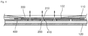
- FIG. 4 is a cross-sectional view schematically illustrating an inner structure of a reference cassette for a fluorescence type immunoassay diagnostic apparatus according to an exemplary embodiment of the present invention.
- a reference cassette for a fluorescence type immunoassay diagnostic apparatus may be for being inserted into an immunoassay diagnostic apparatus in order to test measurement accuracy of the immunoassay diagnostic apparatus diagnosing a disease from a biopsy specimen using fluorescence and generating fluorescence by a test light of an optical module, may comprise a case (100), and a fluorescence glass (200), and may further include a mask (300) and a fixing guide (400).
- the case (100) is configured to be insertable into the immunoassay diagnostic apparatus, and is formed to have an accommodating space to accommodating components such as the fluorescence glass (200) and so on.
- An opening unit (102) is formed at a partial area of an upper surface of the case (100) so that an inner space of the case (100) can be exposed, and the opening unit (102) can be protected by a separate transparent cover.
- the case (100) may be formed to have an accommodating space therein, and include an upper case (120) and a lower case (110) which are separately formed and can be formed to have a structure coupled to each other.
- the lower case (110) forms a base of the case (100) and components are coupled to an inner side surface of the lower case (110), and in this state, the upper case (120) is coupled to an upside of the lower case (110).
- the opening unit (102) is formed at a center portion of an upper surface of the upper case (120), and a body fluid injection hole (101) is formed at one side of the upper surface of the upper case (120) so that body fluid specimen can be absorbably injected into the body fluid injection hole (101).
- the reference cassette may not need the body fluid injection hole (101), but the body fluid injection hole (101) may be included in the reference cassette to have an identical structure to an actual cassette.
- a plurality of sheets of fluorescence glass (200) is disposed in the inner space of the case (100) to be exposed to the outside of the case (100) through the opening unit (102) of the case (100).
- the fluorescence glass (200) may be made of lanthanide series material, and be configured to generate fluorescence by the test light of the optical module and constantly maintain fluorescence characteristics. Europium, terbium and so on can be used as the lanthanide series material.
- the fluorescence characteristics of the fluorescence glass (200) is constantly maintained, the change does not occur in the characteristics, and therefore, in the process of testing measurement accuracy regarding fluorescence detection of the immunoassay diagnostic apparatus, the accuracy of the test may be improved.
- the reference cassette comprising the fluorescence glass (200) does not have the change in the characteristics of the fluorescence glass (200) or heat deterioration and therefore the measurement accuracy may not be lowered even it is continuously used and there is advantage that it can be used semi-permanently.
- the fluorescence detection at a specific area by the optical module may not be easy and be inaccurate, and therefore a separate mask (300) that can limit an outside exposure area of the fluorescence glass (200) to a specific area is installed.
- the mask (300) is arranged at the inside of the case (100) to be located on an upper surface of the fluorescence glass (200).
- a plurality of slits (310) are formed at the mask (300), and the fluorescence glass (200) is configured to be exposed to the outside of the case (100) through the slits (310) of the mask (300).
- the reaction area of a specimen strip to which fluorescence is applied is formed in a line shape crossing the specimen strip, the slit (310) may be lengthily formed to extend in one direction and have a shape similar to the reaction area of the specimen strip, and the fluorescence glass (200) is outwardly exposed through the slit (310) with the line shape.
- test light of the optical module is applied to the fluorescence glass (200) through the slit (310), and the fluorescence generated from the fluorescence glass (200) by the application of the lest light is configured to be emitted to the optical module through the slit (310).
- the mask (300) is made of material which is capable of blocking the light, and is formed in a shape of a thin plate having thin thickness to minimize shadow generated when the test light and the fluorescence pass through the slit (310).
- the material with high stiffness for example, metal material can be used to reinforce flexural strength of the mask (300).
- the mask (300) is arranged to contact the upper surface of the fluorescence glass (200) in order to minimize the shadow generated due to the thickness of the slit (310) of the mask (300).
- a fixing guide (400) having a plurality of insertion coupling holes (410) is coupled in the inside of the case (100).
- the fixing guide (400) may be formed in a shape of flat plate.
- the fluorescence glass (200) is implemented in multiple pieces, each of the pieces of the fluorescence glass (200) is insertedly coupled to a respective insertion coupling hole (410) of the fixing guide (400), and the mask (300) is coupled to the fixing guide (400) such that each slit (310) can limit an outside exposure area of each piece of the fluorescence glass (200) to a slit (310) area.
- the fixing guide (400) is safely coupled inside the case (100) to a bottom surface of the lower case (110), the fluorescence glass (200) is insertedly coupled to each of the insertion holes (410) of the fixing guide (400), and in this state, the mask (300) is coupled to the upper side of the fixing guide (400).
- the mask (300) is positioned so that each of the plurality of the slits (310) can be located on the upper side of the fluorescence glass (200) and the outside exposure area of outside exposure area is limited to the slit (310) area.
- One or more guide protrusions (420) are formed at the fixing guide (400) to guide a position which is coupled with the mask (300), and one or more guide holes (320) are formed at the mask (300) to be insertedly coupled with the guide protrusions (420). Therefore, the position of the mask (300) is guided by coupling the guide protrusion (420) and the guide hole (320) to each other so that the mask (300) can be fixed to a precise location, and the slit (310) of the mask (300) is positioned on the upper side of the fluorescence glass (200) and therefore the outside exposure area of the fluorescence glass (200) can be located at the accurate and proper location.
- the upper surface of the fluorescence glass (200) forms a same plane as an upper surface of the fixing guide (400), and as shown in FIG. 3(b) the mask (300) is coupled to the fixing guide (400) to be contacted with the upper surface of the fixing guide (400) and the upper surface of the fluorescence glass (200).
- the mask (300) with the thin plate shape is arranged to be contacted with the upper surface of the fluorescence glass (200), and therefore the shadow caused by the thickness of the slit (310) can be minimized, the problem of lowering the detection amount of the light by the shadow may be minimized, and the accuracy can be improved.
- a horizontal guide hole (432) and a vertical guide hole (431) may be formed at one end portion of the fixing guide (400) to guide the safe coupling location of the fixing guide (400) with respect to the case (100), and a horizontal guide protrusion (112) and a vertical guide protrusion (111) are protrudingly formed on the bottom surface of the case (100) to be insertedly interlocked with the horizontal guide hole (432) and the vertical guide hole (431), respectively.
- the fixing guide (400) can be securely fixed to an accurate location inside the case (100), and the fluorescence glass (200) and the mask (300) coupled with the fixing guide (400) can be fixed to a precise location as well.
- the slit (310) of the mask (300) and the fluorescence glass (200) can be arrange such that they cross the opening unit (102) of the case (100) in one direction in a state that they are arranged inside the case (100) by the fixing guide (400). As described above, this is for having a line shape like a reaction area of a general specimen strip, and accordingly, if the test light is applied, the fluorescence with a line shape along the slit (310) is generated.
Landscapes
- Health & Medical Sciences (AREA)
- Life Sciences & Earth Sciences (AREA)
- Immunology (AREA)
- Chemical & Material Sciences (AREA)
- Pathology (AREA)
- Biochemistry (AREA)
- General Health & Medical Sciences (AREA)
- General Physics & Mathematics (AREA)
- Physics & Mathematics (AREA)
- Analytical Chemistry (AREA)
- Engineering & Computer Science (AREA)
- Molecular Biology (AREA)
- Biomedical Technology (AREA)
- Hematology (AREA)
- Urology & Nephrology (AREA)
- Nuclear Medicine, Radiotherapy & Molecular Imaging (AREA)
- Biotechnology (AREA)
- Cell Biology (AREA)
- Microbiology (AREA)
- Food Science & Technology (AREA)
- Medicinal Chemistry (AREA)
- Investigating, Analyzing Materials By Fluorescence Or Luminescence (AREA)
Description
- The present invention is generally related to a reference cassette for a fluorescence type immunoassay diagnostic apparatus. More specifically, the present invention is related to a reference cassette for a fluorescence type immunoassay diagnostic apparatus in which, by arranging fluorescence glass, which does not change in characteristics and is capable of constantly maintaining fluorescence characteristics, inside a case, in a process of testing measurement accuracy regarding fluorescence detection of the immunoassay diagnostic apparatus, reference measurement information regarding the fluorescence detection can be precisely provided and therefore the accuracy of the test can be improved, because the change in characteristics and heat deterioration of the fluorescence glass do not occur, the measurement accuracy may not be lowered even it is continuously used and it can be used semi-permanently, and by having a mask at which slits limiting an outside exposure area of the fluorescence glass to a specific area are formed, the fluorescence having the same shape as the reaction area of the actually used specimen strip can be generated.
- Generally, a test method used in disease diagnosis is based on color development, fluorescence and so on by enzyme reaction, but recently immunoassay using immunization reaction between an antigen and an antibody is also being used. Such immunoassay methods mainly label antibodies with radioisotopes or fluorescent substances to identify the presence or absence of antigens, and label type biosensors are used to quantify the intensity of radiation or fluorescence.
- Conventional immunoassay methods have used a method of measuring a signal obtained by labeling antigens or antibodies with radioactive substances, luminescent substances or fluorescent substances, and optical measurement methods such as Enzyme Linked Immunosorbent Assays (ELISAs) combining photolabels with catalytic reactions of enzymes and Western blotting. Those methods have disadvantages in that complex procedures that can be performed primarily by laboratory-based skilled researchers are required, the devices for analysis are expensive and large-scale devices, and long analysis time is needed.
- Because antibodies, which are the target substance of an immune sensor, are present in very low concentrations in biological samples such as whole blood, serum, urine and so on, the immune sensor requires to have a signaling technology which is much more highly sensitive than the biosensor technology of detecting other substances in terms of detection limit of the sensor. In addition, since the structure of protein such as antibodies or protein antigens are easily altered by changes in the external environment, the recognition portion of the antigen or antibody is deteriorated, and thus unique biometric recognition function is easily lost. Because the immune sensor requires to perform analysis in the solid form, the production of a sensor surface suitable for the biopsy materials that can maintain the activation of the biopsy materials, the immobilization technology of the biopsy materials which can increase the detection limit, and the measurement method transforming biometric recognition reaction to quantified signals are needed.
- Rapid diagnostic test kits for immunoassay are test instruments for point-of-care that is capable of performing diagnostic test using biopsy specimens such as blood, urine, and saliva. Examples of such rapid diagnostic test kits include pregnancy diagnosis kits, AIDS diagnosis kits, and so on.
- Those diagnostic devices require to establish a method capable of detecting biomaterial (protein or DNA, etc.) for diagnosis. A fluorescent labeling method using an organic dye or the like has been known as a conventional method for detecting the biomaterial. The fluorescent label emits various colors depending on types to provide a detection means for a target biomaterial.
- The immunoassay diagnostic devices use a specimen strip capable of absorbing and supplying biopsy specimen through capillary phenomenon, and a plurality of reaction areas are formed at the specimen strip by applying different reaction material to each of the reaction areas. In the plurality of reaction regions, each reactive substance is combined with a biopsy specimen having a specific disease to form a fluorescent reaction complex, and the fluorescent reaction complex generates fluorescence when light is applied. Accordingly, after inserting the specimen strip into the device, the test light is applied to the specimen strip from a light source, and fluorescence generated from the reaction region of the specimen strip is detected by an optical system, thereby diagnosing a specific disease associated with the biopsy specimen.
- As those types of the immunoassay diagnostic devices are used for a long time, the measurement accuracy may be deteriorated due to an abnormality in the optical system or other control unit, and a measurement error may occur because of the change in the characteristics of the reaction material applied to the specimen strip. Therefore, it is necessary for the immunoassay diagnosis devices using a fluorescent type specimen strip to periodically check whether the measurement accuracy of the immunoassay diagnosis device is accurate.
- In order to test the measurement accuracy of the immunoassay diagnostic device, a separate reference cassette is used, and the reference cassette is manufactured in a state that a test strip is accommodated therein and a fluorescent substance in an unmodified standard state is applied to the test strip. The reference cassette is inserted into the device to apply test light, and fluorescence generated from the fluorescent material of the test strip is detected to check whether a measurement error occurs in the device. That is, if the detection amount of the fluorescence detected by inserting the reference cassette into the device is different from a predetermined standard detection amount, an error occurs in the device, and an error occurrence alarm sign may be output through a display unit of the device.
- Accordingly, the reference cassette for testing the measurement accuracy of the immunoassay diagnostic device requires to be manufactured very precisely, and the fluorescent material applied to the test strip of the reference cassette also needs to be maintained constantly in a standard state in which the characteristics are not changed. However, the fluorescent substance is easily denatured by the external environment due to its characteristics and therefore it is difficult to maintain the characteristics of the standard state, and in this case, the reference cassette cannot perform normal function as the reference cassette for testing the measurement accuracy of the immunoassay diagnostic device.
- Therefore, in order to precisely check the measurement accuracy of the immunoassay diagnostic device, stably maintaining the standard state of the reference cassette is highly important, and recently the demand and necessity thereof are increasing.
-
WO 2017/199510 A1 discloses a reference body with a support body provided with a first light transmission part, a second light transmission part, a first accommodation space and a second accommodation space; a first fluorescent body that is accommodated in the first accommodation space and emits first fluorescence of a second wavelength band when irradiated via the first light transmission part with first excitation light of a first wavelength band; a second fluorescent body that is accommodated in the second accommodation space and emits second fluorescence of the second wavelength band when irradiated via the second light transmission part with second excitation light of the first wavelength band; and a light blocking part disposed between the first accommodation space and second accommodation space. -
US 2013/230845 A1 discloses a system comprised of an apparatus and a test device. The test device and the apparatus are designed to interact to determine the presence or absence of an analyte of interest in a sample placed on the test device. - To solve the problem of the conventional art, the purpose of the present invention may be for providing a reference cassette for a fluorescence type immunoassay diagnostic apparatus in which, by arranging fluorescence glass, which does not change in characteristics and is capable of constantly maintaining fluorescence characteristics, inside a case, in a process of testing measurement accuracy regarding fluorescence detection of the immunoassay diagnostic apparatus, reference measurement information regarding the fluorescence detection can be precisely provided and therefore the accuracy of the test can be improved, because the change in characteristics and heat deterioration of the fluorescence glass do not occur, the measurement accuracy may not be lowered even it is continuously used and it can be used semi-permanently.
- Another purpose of the present invention may be for providing a reference cassette for a fluorescence type immunoassay diagnostic apparatus in which, by having a mask at which slits limiting an outside exposure area of the fluorescence glass to a specific area are formed, the fluorescence having the same shape as the reaction area of the actually used specimen strip can be generated and therefore more accurate reference measurement information can be provided.
- Still another purpose of the present invention may be for providing a reference cassette for a fluorescence type immunoassay diagnostic apparatus in which by guiding the coupling location of the fluorescence glass and the mask, the position of the fluorescence glass and the mask can be precisely maintained and accordingly the test accuracy can be improved.
- Still another purpose of the present invention may be for providing a reference cassette for a fluorescence type immunoassay diagnostic apparatus in which a mask is formed in a metal plate shape and is arranged to contact the upper surface of fluorescence glass and therefore during a process that test light and fluorescence pass through the slit of the mask the influence of the shadow can be minimized and the fluorescence measurement accuracy can be improved.
- In view of the above-mentioned problems, the present invention provides a reference cassette in accordance with claim 1.
- According to the present invention, a reference cassette for a fluorescence immunoassay diagnostic apparatus which is inserted into the apparatus diagnosing a disease from a biopsy specimen using fluorescence and generates fluorescence by a test light of an optical module, the reference cassette for the fluorescence immunoassay diagnostic apparatus may comprise: a case configured to be insertable into the fluorescence immunoassay diagnostic apparatus, wherein an opening is formed at at least a part of an upper side of the case so that an inner space of the case is exposed to an outside of the case; and a fluorescence glass disposed at the inner space of the case so that the fluorescence glass is exposed to the outside of the case through the opening of the case, wherein the fluorescence glass is configured to generate the fluorescence by the test light of the optical module and constantly maintain fluorescence characteristics.
- According to the invention, a mask is disposed on an upper surface of the fluorescence glass inside the case so that an area of the fluorescence glass exposed to the outside of the case can be limited to a specific area of the fluorescence glass.
- Additionally, the mask has one or more slits, the fluorescence glass is exposed through the slits, the test light of the optical module is applied to the fluorescence glass through the slits, and the fluorescence generated by the fluorescence glass is emitted to the optical module through the slits.
- Further, a separate fixing guide having a plurality of insertion coupling holes is coupled to an inside of the case, the fluorescence glass includes a plurality of pieces of the fluorescence glass, each piece of the fluorescence glass may be insertedly coupled to a respective insertion coupling hole of the fixing guide, and the mask is coupled to the fixing guide so that each of the slits can limit an outside exposure area of the fluorescence glass to a slit area.
- In addition, a guide protrusion may be formed at the fixing guide to guide a coupling location of the mask, and a guide hole may be formed at the mask to be insertedly coupled with the guide protrusion.
- According to the invention, an upper surface of the fluorescence glass and an upper surface of the fixing guide are in a same plane as each other in a state that the fluorescence glass is insertedly coupled to the insertion coupling holes of the fixing guide, and the mask is coupled to the fixing guide to contact the upper surface of the fluorescence glass and the upper surface of the fixing guide.
- Further, the slits of the mask and the fluorescence glass may cross the opening of the case in one direction in a state that the slits of the mask and the fluorescence glass are arranged inside the case by the fixing guide.
- The present invention has an advantageous technical effect in which, by arranging fluorescence glass, which does not change in characteristics and is capable of constantly maintaining fluorescence characteristics, inside a case, in a process of testing measurement accuracy regarding fluorescence detection of a immunoassay diagnostic apparatus, reference measurement information regarding the fluorescence detection can be precisely provided and therefore the accuracy of the test can be improved, and because the change in characteristics and heat deterioration of the fluorescence glass do not occur, the measurement accuracy may not be lowered even it is continuously used and it can be used semi-permanently.
- Additionally, there is an advantageous technical effect in which, by having a mask at which slits limiting an outside exposure area of the fluorescence glass to a specific area are formed, the fluorescence having the same shape as the reaction area of the actually used specimen strip can be generated and therefore more accurate reference measurement information can be provided.
- In addition, there may be advantageous technical effect in which, by guiding the coupling location of the fluorescence glass and the mask, the position of the fluorescence glass and the mask can be precisely maintained and accordingly the test accuracy can be improved.
- Further, there may be advantageous technical effect in which, in which a mask is formed in a metal plate shape and is arranged to contact the upper surface of fluorescence glass and therefore during a process that test light and fluorescence pass through the slit of the mask the influence of the shadow can be minimized and the fluorescence measurement accuracy can be improved.
-
-
FIG. 1 is a perspective view schematically illustrating an outward appearance of a reference cassette for a fluorescence type immunoassay diagnostic apparatus according to an exemplary embodiment of the present invention, -
FIG. 2 is an exploded perspective view schematically illustrating specific configuration of a reference cassette for a fluorescence type immunoassay diagnostic apparatus according to an exemplary embodiment of the present invention, -
FIG. 3 is a view schematically illustrating a mask coupling arrangement structure of a reference cassette for a fluorescence type immunoassay diagnostic apparatus according to an exemplary embodiment of the present invention, and -
FIG. 4 is a cross-sectional view schematically illustrating an inner structure of a reference cassette for a fluorescence type immunoassay diagnostic apparatus according to an exemplary embodiment of the present invention. - Hereinafter, preferred embodiments of the present invention will be described in detail with reference to the accompanying drawings. Throughout this document, reference should be made to the drawings, in which the same reference numerals and symbols will be used to designate the same or like components. Additionally, in the following description of the present invention, detailed descriptions of known components and functions incorporated herein will be omitted in the case that the subject matter of the present invention may be rendered unclear thereby.
-
FIG. 1 is a perspective view schematically illustrating an outward appearance of a reference cassette for a fluorescence type immunoassay diagnostic apparatus according to an exemplary embodiment of the present invention,FIG. 2 is an exploded perspective view schematically illustrating specific configuration of a reference cassette for a fluorescence type immunoassay diagnostic apparatus according to an exemplary embodiment of the present invention,FIG. 3 is a view schematically illustrating a mask coupling arrangement structure of a reference cassette for a fluorescence type immunoassay diagnostic apparatus according to an exemplary embodiment of the present invention, andFIG. 4 is a cross-sectional view schematically illustrating an inner structure of a reference cassette for a fluorescence type immunoassay diagnostic apparatus according to an exemplary embodiment of the present invention. - A reference cassette for a fluorescence type immunoassay diagnostic apparatus according to an exemplary embodiment of the present invention may be for being inserted into an immunoassay diagnostic apparatus in order to test measurement accuracy of the immunoassay diagnostic apparatus diagnosing a disease from a biopsy specimen using fluorescence and generating fluorescence by a test light of an optical module, may comprise a case (100), and a fluorescence glass (200), and may further include a mask (300) and a fixing guide (400).
- The case (100) is configured to be insertable into the immunoassay diagnostic apparatus, and is formed to have an accommodating space to accommodating components such as the fluorescence glass (200) and so on. An opening unit (102) is formed at a partial area of an upper surface of the case (100) so that an inner space of the case (100) can be exposed, and the opening unit (102) can be protected by a separate transparent cover.
- The case (100) may be formed to have an accommodating space therein, and include an upper case (120) and a lower case (110) which are separately formed and can be formed to have a structure coupled to each other. The lower case (110) forms a base of the case (100) and components are coupled to an inner side surface of the lower case (110), and in this state, the upper case (120) is coupled to an upside of the lower case (110). The opening unit (102) is formed at a center portion of an upper surface of the upper case (120), and a body fluid injection hole (101) is formed at one side of the upper surface of the upper case (120) so that body fluid specimen can be absorbably injected into the body fluid injection hole (101). The reference cassette may not need the body fluid injection hole (101), but the body fluid injection hole (101) may be included in the reference cassette to have an identical structure to an actual cassette.
- A plurality of sheets of fluorescence glass (200) is disposed in the inner space of the case (100) to be exposed to the outside of the case (100) through the opening unit (102) of the case (100). The fluorescence glass (200) may be made of lanthanide series material, and be configured to generate fluorescence by the test light of the optical module and constantly maintain fluorescence characteristics. Europium, terbium and so on can be used as the lanthanide series material.
- Because the fluorescence characteristics of the fluorescence glass (200) is constantly maintained, the change does not occur in the characteristics, and therefore, in the process of testing measurement accuracy regarding fluorescence detection of the immunoassay diagnostic apparatus, the accuracy of the test may be improved.
- The reference cassette comprising the fluorescence glass (200) does not have the change in the characteristics of the fluorescence glass (200) or heat deterioration and therefore the measurement accuracy may not be lowered even it is continuously used and there is advantage that it can be used semi-permanently.
- If an extensive area of the fluorescence glass (200) is exposed to the outside of the case (100) through the opening unit (102) of the case (100), the fluorescence detection at a specific area by the optical module may not be easy and be inaccurate, and therefore a separate mask (300) that can limit an outside exposure area of the fluorescence glass (200) to a specific area is installed.
- The mask (300) is arranged at the inside of the case (100) to be located on an upper surface of the fluorescence glass (200). A plurality of slits (310) are formed at the mask (300), and the fluorescence glass (200) is configured to be exposed to the outside of the case (100) through the slits (310) of the mask (300).
- Generally, in the immunoassay diagnostic apparatus, the reaction area of a specimen strip to which fluorescence is applied is formed in a line shape crossing the specimen strip, the slit (310) may be lengthily formed to extend in one direction and have a shape similar to the reaction area of the specimen strip, and the fluorescence glass (200) is outwardly exposed through the slit (310) with the line shape.
- In this case, the test light of the optical module is applied to the fluorescence glass (200) through the slit (310), and the fluorescence generated from the fluorescence glass (200) by the application of the lest light is configured to be emitted to the optical module through the slit (310).
- The mask (300) is made of material which is capable of blocking the light, and is formed in a shape of a thin plate having thin thickness to minimize shadow generated when the test light and the fluorescence pass through the slit (310). In this example, the material with high stiffness, for example, metal material can be used to reinforce flexural strength of the mask (300). Additionally, it is preferred that the mask (300) is arranged to contact the upper surface of the fluorescence glass (200) in order to minimize the shadow generated due to the thickness of the slit (310) of the mask (300).
- A fixing guide (400) having a plurality of insertion coupling holes (410) is coupled in the inside of the case (100). The fixing guide (400) may be formed in a shape of flat plate. The fluorescence glass (200) is implemented in multiple pieces, each of the pieces of the fluorescence glass (200) is insertedly coupled to a respective insertion coupling hole (410) of the fixing guide (400), and the mask (300) is coupled to the fixing guide (400) such that each slit (310) can limit an outside exposure area of each piece of the fluorescence glass (200) to a slit (310) area.
- Accordingly, as illustrated in
FIG. 2 , the fixing guide (400) is safely coupled inside the case (100) to a bottom surface of the lower case (110), the fluorescence glass (200) is insertedly coupled to each of the insertion holes (410) of the fixing guide (400), and in this state, the mask (300) is coupled to the upper side of the fixing guide (400). The mask (300) is positioned so that each of the plurality of the slits (310) can be located on the upper side of the fluorescence glass (200) and the outside exposure area of outside exposure area is limited to the slit (310) area. - One or more guide protrusions (420) are formed at the fixing guide (400) to guide a position which is coupled with the mask (300), and one or more guide holes (320) are formed at the mask (300) to be insertedly coupled with the guide protrusions (420). Therefore, the position of the mask (300) is guided by coupling the guide protrusion (420) and the guide hole (320) to each other so that the mask (300) can be fixed to a precise location, and the slit (310) of the mask (300) is positioned on the upper side of the fluorescence glass (200) and therefore the outside exposure area of the fluorescence glass (200) can be located at the accurate and proper location.
- In addition, in a state that the fluorescence glass (200) is insertedly coupled to the insertion coupling hole (410) of the fixation guide (400), as illustrated in
FIG. 3(a) the upper surface of the fluorescence glass (200) forms a same plane as an upper surface of the fixing guide (400), and as shown inFIG. 3(b) the mask (300) is coupled to the fixing guide (400) to be contacted with the upper surface of the fixing guide (400) and the upper surface of the fluorescence glass (200). - Like this, the mask (300) with the thin plate shape is arranged to be contacted with the upper surface of the fluorescence glass (200), and therefore the shadow caused by the thickness of the slit (310) can be minimized, the problem of lowering the detection amount of the light by the shadow may be minimized, and the accuracy can be improved.
- Additionally, a horizontal guide hole (432) and a vertical guide hole (431) may be formed at one end portion of the fixing guide (400) to guide the safe coupling location of the fixing guide (400) with respect to the case (100), and a horizontal guide protrusion (112) and a vertical guide protrusion (111) are protrudingly formed on the bottom surface of the case (100) to be insertedly interlocked with the horizontal guide hole (432) and the vertical guide hole (431), respectively.
- Like this, because the position of the fixing guide (400) also can be guided, the fixing guide (400) can be securely fixed to an accurate location inside the case (100), and the fluorescence glass (200) and the mask (300) coupled with the fixing guide (400) can be fixed to a precise location as well.
- And, the slit (310) of the mask (300) and the fluorescence glass (200) can be arrange such that they cross the opening unit (102) of the case (100) in one direction in a state that they are arranged inside the case (100) by the fixing guide (400). As described above, this is for having a line shape like a reaction area of a general specimen strip, and accordingly, if the test light is applied, the fluorescence with a line shape along the slit (310) is generated.
- The foregoing descriptions have been presented in order to explain certain principles of the present invention by way of example, and a person having ordinary skill in the art to which the present invention relates could make various modifications and variations. Accordingly, the foregoing embodiments disclosed in the present invention shall be interpreted as being illustrative, while not being limitative. It should be understood that the scope of the present invention shall be defined by the Claims.
Claims (4)
- A reference cassette for a fluorescence immunoassay diagnostic apparatus which is insertable into the apparatus in order to diagnose a disease from a biopsy specimen using fluorescence and configured to generate fluorescence by a test light of an optical module, the reference cassette for the fluorescence immunoassay diagnostic apparatus comprising:a case (100) configured to be insertable into the fluorescence immunoassay diagnostic apparatus, wherein an opening is formed at least a part of an upper side of the case (100) so that an inner space of the case (100) is exposed to an outside of the case (100); anda fluorescence glass (200) disposed at the inner space of the case (100) so that the fluorescence glass (200) is exposed to the outside of the case (100) through the opening of the case (100),wherein the fluorescence glass (200) is configured to generate the fluorescence by the test light of the optical module and constantly maintain fluorescence
characteristics,wherein a mask (300) is disposed on an upper surface of the fluorescence glass (200) inside the case (100) so that an area of the fluorescence glass (200) exposed to the outside of the case (100) is limited to a specific area of the fluorescence glass (200),wherein the mask (300) has one or more slits (310) and the fluorescence glass (200) is exposed through the slits (310),wherein a separate fixing guide (400) having a plurality of insertion coupling holes (410) is coupled to an inside of the case (100), the fluorescence glass (200) includes a plurality of pieces of the fluorescence glass (200), each piece of the fluorescence glass (200) is insertedly coupled to a respective insertion coupling hole (410) of the fixing guide (400), and the mask (300) is coupled to the fixing guide (400) so that each of the slits (310) limits an outside exposure area of the fluorescence glass (200) to a slit area, andwherein an upper surface of the fluorescence glass (200) and an upper surface of the fixing guide (400) are in a same plane as each other in a state that the fluorescence glass (200) is insertedly coupled to the insertion coupling holes (410) of the fixing guide (400), and the mask (300) is coupled to the fixing guide (400) to contact the upper surface of the fluorescence glass (200) and the upper surface of the fixing guide (400). - . The reference cassette for the fluorescence immunoassay diagnostic apparatus of claim 1,
wherein the reference cassette is configured such that the test light of the optical module is applicable to the fluorescence glass (200) through the slits (310), when the reference cassette is inserted into the fluorescence immunoassay diagnostic apparatus, and the fluorescence generated by the fluorescence glass (200), when the test light of the optical module is applied to the fluorescence glass (200), is emitted to the optical module through the slits (310). - . The reference cassette for the fluorescence immunoassay diagnostic apparatus of claim 1,
wherein a guide protrusion (420) is formed at the fixing guide (400) to guide a coupling location of the mask (300), and a guide hole (320) is formed at the mask (300) to be insertedly coupled with the guide protrusion (420). - . The reference cassette for the fluorescence immunoassay diagnostic apparatus of any one of the preceding claims,
wherein the slits (310) of the mask (300) and the fluorescence glass (200) cross the opening of the case (100) in one direction in a state that the slits (310) of the mask (300) and the fluorescence glass (200) are arranged inside the case (100) by the fixing guide (400).
Applications Claiming Priority (2)
| Application Number | Priority Date | Filing Date | Title |
|---|---|---|---|
| KR1020180172630A KR102224374B1 (en) | 2018-12-28 | 2018-12-28 | Reference cassette for fluorescence type diagnostic apparatus for immunoassay |
| PCT/KR2019/017352 WO2020138764A1 (en) | 2018-12-28 | 2019-12-10 | Reference cassette for fluorescence immunoassay diagnostic device |
Publications (3)
| Publication Number | Publication Date |
|---|---|
| EP3889585A1 EP3889585A1 (en) | 2021-10-06 |
| EP3889585A4 EP3889585A4 (en) | 2022-09-21 |
| EP3889585B1 true EP3889585B1 (en) | 2025-06-25 |
Family
ID=71129866
Family Applications (1)
| Application Number | Title | Priority Date | Filing Date |
|---|---|---|---|
| EP19903149.3A Active EP3889585B1 (en) | 2018-12-28 | 2019-12-10 | Reference cassette for fluorescence immunoassay diagnostic device |
Country Status (4)
| Country | Link |
|---|---|
| US (1) | US12111316B2 (en) |
| EP (1) | EP3889585B1 (en) |
| KR (1) | KR102224374B1 (en) |
| WO (1) | WO2020138764A1 (en) |
Family Cites Families (8)
| Publication number | Priority date | Publication date | Assignee | Title |
|---|---|---|---|---|
| US7887750B2 (en) * | 2004-05-05 | 2011-02-15 | Bayer Healthcare Llc | Analytical systems, devices, and cartridges therefor |
| JP2013146263A (en) * | 2011-12-21 | 2013-08-01 | Azbil Corp | Microorganism detecting apparatus calibration method and microorganism detecting apparatus calibration kit |
| JP6231999B2 (en) * | 2012-03-01 | 2017-11-15 | クイデル コーポレーション | Interactive testing device and apparatus having timing mechanism |
| KR101516563B1 (en) * | 2013-09-13 | 2015-05-04 | 전자부품연구원 | Diagnostic strip insertion type reading device |
| KR101661986B1 (en) * | 2015-04-22 | 2016-10-11 | 프리시젼바이오 주식회사 | diagnostic apparatus |
| KR101909599B1 (en) | 2016-02-26 | 2018-10-19 | 프리시젼바이오 주식회사 | Diagnostic apparatus for immunoassay |
| CN109154570A (en) * | 2016-05-19 | 2019-01-04 | 浜松光子学株式会社 | The correction reference body of fluorescence determination device |
| KR101898786B1 (en) * | 2016-12-21 | 2018-09-13 | 주식회사 녹십자엠에스 | Strip for measuring blood-lipid |
-
2018
- 2018-12-28 KR KR1020180172630A patent/KR102224374B1/en active Active
-
2019
- 2019-12-10 EP EP19903149.3A patent/EP3889585B1/en active Active
- 2019-12-10 US US17/418,817 patent/US12111316B2/en active Active
- 2019-12-10 WO PCT/KR2019/017352 patent/WO2020138764A1/en not_active Ceased
Also Published As
| Publication number | Publication date |
|---|---|
| US12111316B2 (en) | 2024-10-08 |
| EP3889585A1 (en) | 2021-10-06 |
| EP3889585A4 (en) | 2022-09-21 |
| WO2020138764A1 (en) | 2020-07-02 |
| KR102224374B1 (en) | 2021-03-09 |
| KR20200082233A (en) | 2020-07-08 |
| US20220074933A1 (en) | 2022-03-10 |
Similar Documents
| Publication | Publication Date | Title |
|---|---|---|
| US11693019B2 (en) | Automated liquid-phase immunoassay apparatus | |
| US10852299B2 (en) | Optical assay device with pneumatic sample actuation | |
| EP2795328B1 (en) | Integrated test device for optical and electrochemical assays | |
| US7799558B1 (en) | Ligand binding assays on microarrays in closed multiwell plates | |
| FI76432B (en) | FARING REQUIREMENTS FOR THE CONSTITUTION OF THE ELEMENT I LOESNING MED EN LJUSLEDARE. | |
| JP4918591B2 (en) | Directional flow assay device | |
| EP2820420B1 (en) | Interactive test device and apparatus with timing mechanism | |
| NO332532B1 (en) | A method for detecting a malantigen in a fluid sample as well as a disposable device suitable for practicing said method. | |
| WO2007007849A1 (en) | Analyzer and analyzing method | |
| WO2015070701A1 (en) | Test strip card | |
| US20030119030A1 (en) | Immunoassay diagnostic probe and a method for use thereof | |
| EP2449382B1 (en) | Magnetic sensor device, method of operating such a device and sample | |
| EP3211419B1 (en) | Device for immunochromatographic assay | |
| Jović et al. | Engineering a diagnostic platform based on a spatially resolved electrochemiluminescence immunoassay for low-plex biomarker detection at point-of-care: mild traumatic brain injury and cardiac applications | |
| US12111316B2 (en) | Reference cassette for fluorescence immunoassay diagnostic device | |
| JP4695025B2 (en) | Biological and chemical reaction analysis kit | |
| KR102530556B1 (en) | Diagnostic cartridge for immunodiagnosis and diagnostic device and system using the same | |
| KR20200134689A (en) | Diagnostic apparatus for immunoassay | |
| WO2007016665A2 (en) | Single use fluorescent assays for determination of analytes | |
| WO2024033027A1 (en) | Reader system for a lateral flow test and according method | |
| JP2004325396A (en) | Method for evaluating sensitivity of signal reader | |
| KR20210085833A (en) | Test strip for immunoassay diagnosis using electric capacitance sensor | |
| JPH1123468A (en) | Fluorescence analyzer on solid surface using optical waveguide | |
| HK1079280A1 (en) | Accessible assay device and method of use | |
| HK1079280B (en) | Accessible assay device and method of use |
Legal Events
| Date | Code | Title | Description |
|---|---|---|---|
| STAA | Information on the status of an ep patent application or granted ep patent |
Free format text: STATUS: THE INTERNATIONAL PUBLICATION HAS BEEN MADE |
|
| PUAI | Public reference made under article 153(3) epc to a published international application that has entered the european phase |
Free format text: ORIGINAL CODE: 0009012 |
|
| STAA | Information on the status of an ep patent application or granted ep patent |
Free format text: STATUS: REQUEST FOR EXAMINATION WAS MADE |
|
| 17P | Request for examination filed |
Effective date: 20210702 |
|
| AK | Designated contracting states |
Kind code of ref document: A1 Designated state(s): AL AT BE BG CH CY CZ DE DK EE ES FI FR GB GR HR HU IE IS IT LI LT LU LV MC MK MT NL NO PL PT RO RS SE SI SK SM TR |
|
| DAV | Request for validation of the european patent (deleted) | ||
| DAX | Request for extension of the european patent (deleted) | ||
| A4 | Supplementary search report drawn up and despatched |
Effective date: 20220822 |
|
| RIC1 | Information provided on ipc code assigned before grant |
Ipc: G01N 33/543 20060101ALI20220816BHEP Ipc: G01N 33/558 20060101ALI20220816BHEP Ipc: G01N 21/64 20060101AFI20220816BHEP |
|
| STAA | Information on the status of an ep patent application or granted ep patent |
Free format text: STATUS: EXAMINATION IS IN PROGRESS |
|
| 17Q | First examination report despatched |
Effective date: 20230717 |
|
| GRAP | Despatch of communication of intention to grant a patent |
Free format text: ORIGINAL CODE: EPIDOSNIGR1 |
|
| STAA | Information on the status of an ep patent application or granted ep patent |
Free format text: STATUS: GRANT OF PATENT IS INTENDED |
|
| INTG | Intention to grant announced |
Effective date: 20250210 |
|
| GRAS | Grant fee paid |
Free format text: ORIGINAL CODE: EPIDOSNIGR3 |
|
| GRAA | (expected) grant |
Free format text: ORIGINAL CODE: 0009210 |
|
| STAA | Information on the status of an ep patent application or granted ep patent |
Free format text: STATUS: THE PATENT HAS BEEN GRANTED |
|
| AK | Designated contracting states |
Kind code of ref document: B1 Designated state(s): AL AT BE BG CH CY CZ DE DK EE ES FI FR GB GR HR HU IE IS IT LI LT LU LV MC MK MT NL NO PL PT RO RS SE SI SK SM TR |
|
| REG | Reference to a national code |
Ref country code: GB Ref legal event code: FG4D |
|
| REG | Reference to a national code |
Ref country code: CH Ref legal event code: EP |
|
| REG | Reference to a national code |
Ref country code: DE Ref legal event code: R096 Ref document number: 602019071759 Country of ref document: DE |
|
| REG | Reference to a national code |
Ref country code: CH Ref legal event code: EP |
|
| REG | Reference to a national code |
Ref country code: IE Ref legal event code: FG4D |
|
| REG | Reference to a national code |
Ref country code: SK Ref legal event code: T3 Ref document number: E 46825 Country of ref document: SK |
|
| PG25 | Lapsed in a contracting state [announced via postgrant information from national office to epo] |
Ref country code: FI Free format text: LAPSE BECAUSE OF FAILURE TO SUBMIT A TRANSLATION OF THE DESCRIPTION OR TO PAY THE FEE WITHIN THE PRESCRIBED TIME-LIMIT Effective date: 20250625 |
|
| REG | Reference to a national code |
Ref country code: LT Ref legal event code: MG9D |
|
| PG25 | Lapsed in a contracting state [announced via postgrant information from national office to epo] |
Ref country code: NO Free format text: LAPSE BECAUSE OF FAILURE TO SUBMIT A TRANSLATION OF THE DESCRIPTION OR TO PAY THE FEE WITHIN THE PRESCRIBED TIME-LIMIT Effective date: 20250925 Ref country code: GR Free format text: LAPSE BECAUSE OF FAILURE TO SUBMIT A TRANSLATION OF THE DESCRIPTION OR TO PAY THE FEE WITHIN THE PRESCRIBED TIME-LIMIT Effective date: 20250926 |
|
| PG25 | Lapsed in a contracting state [announced via postgrant information from national office to epo] |
Ref country code: BG Free format text: LAPSE BECAUSE OF FAILURE TO SUBMIT A TRANSLATION OF THE DESCRIPTION OR TO PAY THE FEE WITHIN THE PRESCRIBED TIME-LIMIT Effective date: 20250625 |
|
| PG25 | Lapsed in a contracting state [announced via postgrant information from national office to epo] |
Ref country code: HR Free format text: LAPSE BECAUSE OF FAILURE TO SUBMIT A TRANSLATION OF THE DESCRIPTION OR TO PAY THE FEE WITHIN THE PRESCRIBED TIME-LIMIT Effective date: 20250625 |
|
| PG25 | Lapsed in a contracting state [announced via postgrant information from national office to epo] |
Ref country code: RS Free format text: LAPSE BECAUSE OF FAILURE TO SUBMIT A TRANSLATION OF THE DESCRIPTION OR TO PAY THE FEE WITHIN THE PRESCRIBED TIME-LIMIT Effective date: 20250925 |
|
| PG25 | Lapsed in a contracting state [announced via postgrant information from national office to epo] |
Ref country code: LV Free format text: LAPSE BECAUSE OF FAILURE TO SUBMIT A TRANSLATION OF THE DESCRIPTION OR TO PAY THE FEE WITHIN THE PRESCRIBED TIME-LIMIT Effective date: 20250625 |
|
| REG | Reference to a national code |
Ref country code: NL Ref legal event code: MP Effective date: 20250625 |
|
| PG25 | Lapsed in a contracting state [announced via postgrant information from national office to epo] |
Ref country code: NL Free format text: LAPSE BECAUSE OF FAILURE TO SUBMIT A TRANSLATION OF THE DESCRIPTION OR TO PAY THE FEE WITHIN THE PRESCRIBED TIME-LIMIT Effective date: 20250625 |
|
| PG25 | Lapsed in a contracting state [announced via postgrant information from national office to epo] |
Ref country code: PT Free format text: LAPSE BECAUSE OF FAILURE TO SUBMIT A TRANSLATION OF THE DESCRIPTION OR TO PAY THE FEE WITHIN THE PRESCRIBED TIME-LIMIT Effective date: 20251027 |
|
| PG25 | Lapsed in a contracting state [announced via postgrant information from national office to epo] |
Ref country code: IS Free format text: LAPSE BECAUSE OF FAILURE TO SUBMIT A TRANSLATION OF THE DESCRIPTION OR TO PAY THE FEE WITHIN THE PRESCRIBED TIME-LIMIT Effective date: 20251025 |
|
| PG25 | Lapsed in a contracting state [announced via postgrant information from national office to epo] |
Ref country code: SM Free format text: LAPSE BECAUSE OF FAILURE TO SUBMIT A TRANSLATION OF THE DESCRIPTION OR TO PAY THE FEE WITHIN THE PRESCRIBED TIME-LIMIT Effective date: 20250625 |
|
| PGFP | Annual fee paid to national office [announced via postgrant information from national office to epo] |
Ref country code: AT Payment date: 20251222 Year of fee payment: 7 |
|
| PGFP | Annual fee paid to national office [announced via postgrant information from national office to epo] |
Ref country code: CZ Payment date: 20251203 Year of fee payment: 7 |
|
| PG25 | Lapsed in a contracting state [announced via postgrant information from national office to epo] |
Ref country code: PL Free format text: LAPSE BECAUSE OF FAILURE TO SUBMIT A TRANSLATION OF THE DESCRIPTION OR TO PAY THE FEE WITHIN THE PRESCRIBED TIME-LIMIT Effective date: 20250625 |
|
| PG25 | Lapsed in a contracting state [announced via postgrant information from national office to epo] |
Ref country code: EE Free format text: LAPSE BECAUSE OF FAILURE TO SUBMIT A TRANSLATION OF THE DESCRIPTION OR TO PAY THE FEE WITHIN THE PRESCRIBED TIME-LIMIT Effective date: 20250625 |
|
| PGFP | Annual fee paid to national office [announced via postgrant information from national office to epo] |
Ref country code: SK Payment date: 20251203 Year of fee payment: 7 |
|
| PG25 | Lapsed in a contracting state [announced via postgrant information from national office to epo] |
Ref country code: ES Free format text: LAPSE BECAUSE OF FAILURE TO SUBMIT A TRANSLATION OF THE DESCRIPTION OR TO PAY THE FEE WITHIN THE PRESCRIBED TIME-LIMIT Effective date: 20250625 |
|
| PG25 | Lapsed in a contracting state [announced via postgrant information from national office to epo] |
Ref country code: RO Free format text: LAPSE BECAUSE OF FAILURE TO SUBMIT A TRANSLATION OF THE DESCRIPTION OR TO PAY THE FEE WITHIN THE PRESCRIBED TIME-LIMIT Effective date: 20250625 |
|
| PG25 | Lapsed in a contracting state [announced via postgrant information from national office to epo] |
Ref country code: DK Free format text: LAPSE BECAUSE OF FAILURE TO SUBMIT A TRANSLATION OF THE DESCRIPTION OR TO PAY THE FEE WITHIN THE PRESCRIBED TIME-LIMIT Effective date: 20250625 |
|
| PGFP | Annual fee paid to national office [announced via postgrant information from national office to epo] |
Ref country code: DE Payment date: 20251215 Year of fee payment: 7 |
|
| PG25 | Lapsed in a contracting state [announced via postgrant information from national office to epo] |
Ref country code: IT Free format text: LAPSE BECAUSE OF FAILURE TO SUBMIT A TRANSLATION OF THE DESCRIPTION OR TO PAY THE FEE WITHIN THE PRESCRIBED TIME-LIMIT Effective date: 20250625 |
|
| PLBE | No opposition filed within time limit |
Free format text: ORIGINAL CODE: 0009261 |
|
| STAA | Information on the status of an ep patent application or granted ep patent |
Free format text: STATUS: NO OPPOSITION FILED WITHIN TIME LIMIT |
|
| REG | Reference to a national code |
Ref country code: CH Ref legal event code: L10 Free format text: ST27 STATUS EVENT CODE: U-0-0-L10-L00 (AS PROVIDED BY THE NATIONAL OFFICE) Effective date: 20260507 |