EP3889500A1 - Waste heat recovery - Google Patents
Waste heat recovery Download PDFInfo
- Publication number
- EP3889500A1 EP3889500A1 EP19889456.0A EP19889456A EP3889500A1 EP 3889500 A1 EP3889500 A1 EP 3889500A1 EP 19889456 A EP19889456 A EP 19889456A EP 3889500 A1 EP3889500 A1 EP 3889500A1
- Authority
- EP
- European Patent Office
- Prior art keywords
- extending portion
- sleeve
- heat recovery
- duct casing
- recovery boiler
- Prior art date
- Legal status (The legal status is an assumption and is not a legal conclusion. Google has not performed a legal analysis and makes no representation as to the accuracy of the status listed.)
- Granted
Links
Images


Classifications
-
- F—MECHANICAL ENGINEERING; LIGHTING; HEATING; WEAPONS; BLASTING
- F23—COMBUSTION APPARATUS; COMBUSTION PROCESSES
- F23J—REMOVAL OR TREATMENT OF COMBUSTION PRODUCTS OR COMBUSTION RESIDUES; FLUES
- F23J3/00—Removing solid residues from passages or chambers beyond the fire, e.g. from flues by soot blowers
- F23J3/02—Cleaning furnace tubes; Cleaning flues or chimneys
- F23J3/023—Cleaning furnace tubes; Cleaning flues or chimneys cleaning the fireside of watertubes in boilers
-
- F—MECHANICAL ENGINEERING; LIGHTING; HEATING; WEAPONS; BLASTING
- F28—HEAT EXCHANGE IN GENERAL
- F28G—CLEANING OF INTERNAL OR EXTERNAL SURFACES OF HEAT-EXCHANGE OR HEAT-TRANSFER CONDUITS, e.g. WATER TUBES OR BOILERS
- F28G7/00—Cleaning by vibration or pressure waves
-
- F—MECHANICAL ENGINEERING; LIGHTING; HEATING; WEAPONS; BLASTING
- F22—STEAM GENERATION
- F22B—METHODS OF STEAM GENERATION; STEAM BOILERS
- F22B1/00—Methods of steam generation characterised by form of heating method
- F22B1/02—Methods of steam generation characterised by form of heating method by exploitation of the heat content of hot heat carriers
- F22B1/18—Methods of steam generation characterised by form of heating method by exploitation of the heat content of hot heat carriers the heat carrier being a hot gas, e.g. waste gas such as exhaust gas of internal-combustion engines
-
- F—MECHANICAL ENGINEERING; LIGHTING; HEATING; WEAPONS; BLASTING
- F23—COMBUSTION APPARATUS; COMBUSTION PROCESSES
- F23J—REMOVAL OR TREATMENT OF COMBUSTION PRODUCTS OR COMBUSTION RESIDUES; FLUES
- F23J15/00—Arrangements of devices for treating smoke or fumes
- F23J15/06—Arrangements of devices for treating smoke or fumes of coolers
-
- F—MECHANICAL ENGINEERING; LIGHTING; HEATING; WEAPONS; BLASTING
- F23—COMBUSTION APPARATUS; COMBUSTION PROCESSES
- F23J—REMOVAL OR TREATMENT OF COMBUSTION PRODUCTS OR COMBUSTION RESIDUES; FLUES
- F23J3/00—Removing solid residues from passages or chambers beyond the fire, e.g. from flues by soot blowers
-
- F—MECHANICAL ENGINEERING; LIGHTING; HEATING; WEAPONS; BLASTING
- F28—HEAT EXCHANGE IN GENERAL
- F28D—HEAT-EXCHANGE APPARATUS, NOT PROVIDED FOR IN ANOTHER SUBCLASS, IN WHICH THE HEAT-EXCHANGE MEDIA DO NOT COME INTO DIRECT CONTACT
- F28D21/00—Heat-exchange apparatus not covered by any of the groups F28D1/00 - F28D20/00
- F28D21/0001—Recuperative heat exchangers
- F28D21/0003—Recuperative heat exchangers the heat being recuperated from exhaust gases
- F28D21/001—Recuperative heat exchangers the heat being recuperated from exhaust gases for thermal power plants or industrial processes
-
- F—MECHANICAL ENGINEERING; LIGHTING; HEATING; WEAPONS; BLASTING
- F28—HEAT EXCHANGE IN GENERAL
- F28D—HEAT-EXCHANGE APPARATUS, NOT PROVIDED FOR IN ANOTHER SUBCLASS, IN WHICH THE HEAT-EXCHANGE MEDIA DO NOT COME INTO DIRECT CONTACT
- F28D7/00—Heat-exchange apparatus having stationary tubular conduit assemblies for both heat-exchange media, the media being in contact with different sides of a conduit wall
- F28D7/08—Heat-exchange apparatus having stationary tubular conduit assemblies for both heat-exchange media, the media being in contact with different sides of a conduit wall the conduits being otherwise bent, e.g. in a serpentine or zig-zag
- F28D7/082—Heat-exchange apparatus having stationary tubular conduit assemblies for both heat-exchange media, the media being in contact with different sides of a conduit wall the conduits being otherwise bent, e.g. in a serpentine or zig-zag with serpentine or zig-zag configuration
- F28D7/085—Heat-exchange apparatus having stationary tubular conduit assemblies for both heat-exchange media, the media being in contact with different sides of a conduit wall the conduits being otherwise bent, e.g. in a serpentine or zig-zag with serpentine or zig-zag configuration in the form of parallel conduits coupled by bent portions
-
- F—MECHANICAL ENGINEERING; LIGHTING; HEATING; WEAPONS; BLASTING
- F28—HEAT EXCHANGE IN GENERAL
- F28G—CLEANING OF INTERNAL OR EXTERNAL SURFACES OF HEAT-EXCHANGE OR HEAT-TRANSFER CONDUITS, e.g. WATER TUBES OR BOILERS
- F28G1/00—Non-rotary, e.g. reciprocated, appliances
- F28G1/08—Non-rotary, e.g. reciprocated, appliances having scrapers, hammers, or cutters, e.g. rigidly mounted
- F28G1/10—Non-rotary, e.g. reciprocated, appliances having scrapers, hammers, or cutters, e.g. rigidly mounted resiliently mounted
-
- F—MECHANICAL ENGINEERING; LIGHTING; HEATING; WEAPONS; BLASTING
- F22—STEAM GENERATION
- F22B—METHODS OF STEAM GENERATION; STEAM BOILERS
- F22B1/00—Methods of steam generation characterised by form of heating method
- F22B1/02—Methods of steam generation characterised by form of heating method by exploitation of the heat content of hot heat carriers
- F22B1/18—Methods of steam generation characterised by form of heating method by exploitation of the heat content of hot heat carriers the heat carrier being a hot gas, e.g. waste gas such as exhaust gas of internal-combustion engines
- F22B1/1807—Methods of steam generation characterised by form of heating method by exploitation of the heat content of hot heat carriers the heat carrier being a hot gas, e.g. waste gas such as exhaust gas of internal-combustion engines using the exhaust gases of combustion engines
-
- F—MECHANICAL ENGINEERING; LIGHTING; HEATING; WEAPONS; BLASTING
- F22—STEAM GENERATION
- F22B—METHODS OF STEAM GENERATION; STEAM BOILERS
- F22B37/00—Component parts or details of steam boilers
-
- F—MECHANICAL ENGINEERING; LIGHTING; HEATING; WEAPONS; BLASTING
- F28—HEAT EXCHANGE IN GENERAL
- F28F—DETAILS OF HEAT-EXCHANGE AND HEAT-TRANSFER APPARATUS, OF GENERAL APPLICATION
- F28F2230/00—Sealing means
-
- Y—GENERAL TAGGING OF NEW TECHNOLOGICAL DEVELOPMENTS; GENERAL TAGGING OF CROSS-SECTIONAL TECHNOLOGIES SPANNING OVER SEVERAL SECTIONS OF THE IPC; TECHNICAL SUBJECTS COVERED BY FORMER USPC CROSS-REFERENCE ART COLLECTIONS [XRACs] AND DIGESTS
- Y02—TECHNOLOGIES OR APPLICATIONS FOR MITIGATION OR ADAPTATION AGAINST CLIMATE CHANGE
- Y02E—REDUCTION OF GREENHOUSE GAS [GHG] EMISSIONS, RELATED TO ENERGY GENERATION, TRANSMISSION OR DISTRIBUTION
- Y02E20/00—Combustion technologies with mitigation potential
- Y02E20/30—Technologies for a more efficient combustion or heat usage
Definitions
- the present invention relates to an exhaust heat recovery boiler.
- an exhaust heat recovery boiler In an exhaust heat recovery boiler, water flowing through a heat exchanger tube is converted into steam by utilizing heat of exhaust gas, and with this, heat energy is recovered from the exhaust gas.
- the exhaust gas supplied to the exhaust heat recovery boiler contains a large amount of dust, the dust accumulates on the heat exchanger tube, and this lowers recovery efficiency of the heat energy.
- an exhaust heat recovery boiler including a hammering rod is being proposed (see PTL 1, for example).
- the hammering rod is connected to the heat exchanger tube. By applying impact to the hammering rod from outside, the impact is transferred to the heat exchanger tube, and the dust accumulating on the heat exchanger tube falls. Thus, the recovery efficiency of the heat energy can be prevented from lowering.
- the heat exchanger tube is provided in a duct casing through which the exhaust gas flows.
- the hammering rod is connected to the heat exchanger tube.
- an upper part of the hammering rod projects to an outside of the duct casing and is strongly hit by an external mechanism.
- the hammering rod penetrates the duct casing, a seal between the hammering rod and the duct casing needs to be realized.
- both of the heat exchanger tube and the duct casing expand by the heat of the exhaust gas.
- the temperature of the heat exchanger tube does not increase significantly.
- the temperature of the duct casing increases to a temperature close to the temperature of the exhaust gas. Therefore, the amount of thermal expansion of the duct casing is larger than that of the heat exchanger tube, and the duct casing is displaced relative to the hammering rod. Even when the duct casing is displaced relative to the hammering rod as above, the seal between the hammering rod and the duct casing needs to be maintained.
- the present invention was made under these circumstances, and an object of the present invention is to provide an exhaust heat recovery boiler configured such that even when a duct casing is displaced relative to a hammering rod, high seal performance between the hammering rod and the duct casing can be maintained.
- An exhaust heat recovery boiler includes: a duct casing in which exhaust gas flows; a tubular extending portion extending upward from the duct casing; a heat exchanger tube located in the duct casing; a hammering rod connected to the heat exchanger tube in the duct casing and passing through an inside of the extending portion, the hammering rod including an upper part projecting to an outside of the extending portion; and an annular sleeve attached to the upper part of the hammering rod through a packing.
- the extending portion includes an upper flat surface which is located at an upper end of the extending portion, realizes a seal between the upper flat surface and a lower surface of the sleeve, and is annular and flat.
- the seal is realized between the lower surface of the sleeve and the upper flat surface of the extending portion.
- a contact area is large, and therefore, high seal performance can be obtained.
- the duct casing is displaced relative to the hammering rod. Therefore, the extending portion extending from the duct casing is displaced relative to the sleeve attached to the hammering rod.
- the contact area between the sleeve and the extending portion is large. Therefore, even when the sleeve is displaced relative to the extending portion, high seal performance can be maintained.
- the upper flat surface of the extending portion may be in surface-contact with the lower surface of the sleeve.
- the exhaust heat recovery boiler according to another aspect may further include one or a plurality of seal plates located between the lower surface of the sleeve and the upper flat surface of the extending portion and formed in an annular shape.
- the seal between the lower surface of the sleeve and the upper flat surface of the extending portion is realized by using one or a plurality of seal plates.
- the seal plates are slightly displaced relative to each other and gradually fit each other. With this, high seal performance between the hammering rod and the duct casing can be maintained.
- the exhaust heat recovery boiler may further include a plurality of seal plates located between the lower surface of the sleeve and the upper flat surface of the extending portion and formed in an annular shape.
- the plurality of seal plates may include a first seal plate having a thickness which decreases as the first seal plate extends outward in a radial direction and a second seal plate arranged adjacent to the first seal plate and having a thickness which increases as the second seal plate extends outward in the radial direction.
- the exhaust heat recovery boiler includes the first and second seal plates that are so-called tapered plates. Therefore, even when the lower surface of the sleeve is inclined relative to the upper flat surface of the extending portion, or even when the sleeve rattles, the seal plates can fit each other. On this account, high seal performance between the hammering rod and the duct casing can be maintained.
- a central axis of the extending portion may be located closer to a middle side of the duct casing than a central axis of the hammering rod.
- the central axis of the extending portion is located closer to the middle side of the duct casing than the central axis of the hammering rod. Therefore, during the hot state in which the exhaust gas is flowing in the duct casing, the central axis of the extending portion approaches the central axis of the hammering rod. As a result, during the hot state, positional deviation between a central axis of the lower surface of the sleeve and a central axis of the upper flat surface of the extending portion decreases, and therefore, high seal performance between the hammering rod and the duct casing can be maintained.
- the extending portion may include: a cylindrical main body portion extending upward from the duct casing; and an annular horizontal portion extending outward in a radial direction from an upper end part of the main body portion and including an upper surface constituting the upper flat surface.
- the upper surface of the horizontal portion extending outward in the radial direction from the upper end part of the main body portion constitutes the upper flat surface of the extending portion. Therefore, the upper flat surface of the extending portion can be easily formed.
- the above exhaust heat recovery boiler may further include a bellows covering a boundary between the sleeve and the extending portion.
- the extending portion may include an outer wall portion extending downward from a radially outer end part of the horizontal portion.
- the bellows may include an upper end part fixed to an outer peripheral surface of the sleeve and a lower end part fixed to the outer wall portion of the extending portion.
- the exhaust heat recovery boiler includes the bellows covering the boundary between the sleeve and the extending portion, the seal performance between the hammering rod and the duct casing can be improved.
- the lower end part of the bellows is fixed to not the main body portion, which is high in temperature, of the extending portion but the outer wall portion located outside the main body portion in the radial direction, thermal damage of the bellows can be prevented.
- the hammering rod may include: a circular column portion penetrating the sleeve and having a circular section; a square column portion having a square section, a coupling member being fixed to the square column portion, the heat exchanger tube being coupled to the square column portion through the coupling member; and an intermediate portion located between the circular column portion and the square column portion and formed in such a curved shape that a section of the intermediate portion changes from a circular shape to a square shape as the intermediate portion extends from the circular column portion toward the square column portion.
- the portion of the hammering rod which portion penetrates the sleeve has the circular section, the seal between the hammering rod and the sleeve can be easily realized. Moreover, since the portion of the hammering rod to which portion the coupling member is fixed has the square section, the fixing of the coupling member to the hammering rod can be easily performed. In addition, since the hammering rod includes the intermediate portion located between the circular column portion and the square column portion and formed in the curved shape, the dust can be prevented from accumulating at the boundary between the circular column portion and the square column portion.
- the present invention can provide the exhaust heat recovery boiler configured such that even when the duct casing is displaced relative to the hammering rod, high seal performance between the hammering rod and the duct casing can be maintained.
- FIG. 1 is a sectional view showing the exhaust heat recovery boiler 100.
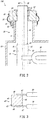
- FIG. 2 is an enlarged view showing an upper part of a hammering rod shown in FIG. 1 and its periphery.
- FIG. 2 is a diagram during a cold state in which exhaust gas is not supplied to the exhaust heat recovery boiler 100.
- the exhaust heat recovery boiler 100 is a facility configured to recover heat energy from the exhaust gas.
- a plurality of exhaust heat recovery boilers 100 according to the present embodiment are provided so as to be stacked on each other in an upper-lower direction.
- the exhaust heat recovery boiler 100 according to the present embodiment includes a duct casing 10, extending portions 20, heat exchanger tubes 30, hammering rods 40, and sleeves 50.
- the exhaust heat recovery boiler 100 according to the present embodiment includes bellows 60. The following will describe these components in order.
- the duct casing 10 is a member constituting part of a duct in which the exhaust gas flows. Upper and lower surfaces of the duct casing 10 are open.
- the duct casing 10 is formed in a tubular shape having a substantially rectangular section.
- the exhaust gas flows downward in the duct casing 10.
- the exhaust gas flowing in the duct casing 10 contains a large amount of dust.
- the exhaust gas of the present embodiment is assumed to be exhaust gas generated in the process of manufacturing cement. However, the exhaust gas is not limited to this.
- the duct casing 10 includes a recess 11 formed such that an outer surface of the duct casing 10 is concave inward.
- the recess 11 is located at an upper portion of one longitudinal end side (left side on a paper surface of FIG. 1 ) of the duct casing 10, and the below-described extending portion 20 is provided at the recess 11.
- the extending portion 20 is a tubular member extending upward from the duct casing 10. As described above, the extending portion 20 is provided at the recess 11 of the duct casing 10. As shown in FIG. 2 , the extending portion 20 includes a cylindrical main body portion 21 extending upward from the duct casing 10, an annular horizontal portion 22 extending outward in a radial direction from an upper end part of the main body portion 21, and a cylindrical outer wall portion 23 extending downward from a radially outer end part of the horizontal portion 22.
- An upper surface of the horizontal portion 22 is an annular flat surface (horizontal surface) and constitutes an upper flat surface 24.
- the upper flat surface 24 is located at an upper end of the extending portion 20 and is in surface-contact with a lower surface of the below-described sleeve 50 to realize a seal between the upper flat surface 24 and the lower surface of the sleeve 50.
- the heat exchanger tubes 30 are located in the duct casing 10, and the exhaust gas flows along outer surfaces of the heat exchanger tubes 30.
- the exhaust heat recovery boiler 100 includes a plurality of heat exchanger tubes 30, and the heat exchanger tubes 30 are arranged at regular intervals in a width direction (direction vertical to the paper surface of FIG. 1 ). Each of the heat exchanger tubes 30 extends in a horizontal direction (left-right direction on the paper surface of FIG. 1 ) while making a turn plural times. Water is supplied to each heat exchanger tube 30 through a water feed header 31. The water supplied to each heat exchanger tube 30 is converted into steam by heat energy of the exhaust gas. After the steam is once recovered by a steam header 32, the steam is supplied to a steam turbine (not shown).
- Both of the heat exchanger tube 30 and the duct casing 10 expand by the heat of the exhaust gas.
- the temperature of the heat exchanger tube 30 does not increase significantly.
- the temperature of the duct casing 10 increases to a temperature close to the temperature of the exhaust gas. Therefore, during a hot state in which the exhaust gas is flowing in the duct casing 10, the thermal expansion of the duct casing 10 is larger than the thermal expansion of the heat exchanger tube 30.
- the steam header 32 to which each heat exchanger tube 30 is connected is supported by the duct casing 10 through a supporting member 33. Therefore, in the vicinity of the steam header 32, the duct casing 10 is hardly displaced relative to the heat exchanger tube 30.
- the duct casing 10 is relatively largely displaced relative to the heat exchanger tube 30.
- the hammering rod 40 is a member which applies impact to the heat exchanger tubes 30 to make the dust, accumulating on the heat exchanger tubes 30, fall.
- the hammering rod 40 is connected to the heat exchanger tubes 30 in the duct casing 10 and passes through an inside of the extending portion 20.
- the hammering rod 40 includes the upper part projecting to an outside of the extending portion 20. When the upper part of the hammering rod 40 is hit by an external mechanism, the impact is applied to the hammering rod 40, and the impact is transferred to each heat exchanger tube 30.
- the hammering rod 40 includes: a circular column portion 42 including the upper part; a square column portion 43 including a lower part; and an intermediate portion 44 located between the circular column portion 42 and the square column portion 43, and these portions are integrally formed.
- the circular column portion 42 penetrates the below-described sleeve 50 and is formed to have a circular section. Since the portion penetrating the sleeve 50 has the circular section as above, the seal (seal by using a below-described packing 51) between the sleeve 50 and the hammering rod 40 can be realized more easily than when the section has a shape other than the circular shape.
- the square column portion 43 is a portion to which the heat exchanger tubes 30 are connected.
- the square column portion 43 is located in the duct casing 10.
- FIG. 3 is a horizontal sectional view showing the square column portion 43.
- the square column portion 43 has a square section and includes a pair of vertical surfaces 45 and a pair of parallel surfaces 46.
- the vertical surfaces 45 are vertical to an extending direction (left-right direction on the paper surface of FIG. 3 ) of the heat exchanger tube 30, and the parallel surfaces 46 are parallel to the extending direction of the heat exchanger tube 30 and perpendicular to the vertical surfaces 45.
- each heat exchanger tube 30 is coupled to the square column portion 43 through a plate-shaped coupling member 47.
- the coupling member 47 is fixed to the hammering rod 40 by welding.
- the section of the portion to which the heat exchanger tube 30 is coupled is square. With this, the coupling member 47 is easily fixed to the hammering rod 40, and the heat exchanger tube 30 can be firmly connected to the hammering rod 40.
- the intermediate portion 44 is a portion located between the circular column portion 42 and the square column portion 43.
- the intermediate portion 44 is formed in such a curved shape that a section of the intermediate portion 44 changes from a circular shape to a square shape as the intermediate portion 44 extends from the circular column portion 42 toward the square column portion 43. If the hammering rod 40 does not include the intermediate portion 44, the dust accumulates on portions (corner portions and the like) of an upper surface of the square column portion 43 which portions protrude from the circular column portion 42. However, since the hammering rod 40 includes the intermediate portion 44 in the present embodiment, the dust can be prevented from accumulating on the square column portion 43.
- a central axis 25 of the extending portion 20 is located closer to a middle side of the duct casing 10 than a central axis 48 of the hammering rod 40.
- the duct casing 10 is relatively largely displaced relative to the heat exchanger tube 30 in the region opposite to the position where the steam header 32 is provided.
- the central axis 25 of the extending portion 20 is not aligned with the central axis 48 of the hammering rod 40 during the cold state, the central axis 25 of the extending portion 20 approaches the central axis 48 of the hammering rod 40 during the hot state.
- the sleeve 50 is a member attached to the upper part (circular column portion 42) of the hammering rod 40. In other words, the hammering rod 40 penetrates an inside of the sleeve 50.
- the sleeve 50 has an annular shape (cylindrical shape having a certain thickness or more), and the lower surface of the sleeve 50 is formed horizontally.
- the sleeve 50 is attached to the hammering rod 40 through the packing 51. When impact is applied to the hammering rod 40, the hammering rod 40 is displaced relative to the sleeve 50 in the upper-lower direction to some extent.
- an annular cover 52 is attached to an upper surface of the sleeve 50 so as to cover the packing 51.
- the lower surface of the sleeve 50 is in surface-contact with the upper flat surface 24 of the extending portion 20, and the seal is realized between the lower surface of the sleeve 50 and the upper flat surface 24 of the extending portion 20.
- the seal is realized between the surfaces, a contact area is large, and therefore, high seal performance can be secured.
- the lower surface of the sleeve 50 and the upper flat surface 24 of the extending portion 20 are not fixed to each other, and the sleeve 50 is movable relative to the extending portion 20 in the horizontal direction.
- the duct casing 10 is relatively largely displaced relative to the heat exchanger tube 30. Therefore, the extending portion 20 extending from the duct casing 10 is displaced relative to the sleeve 50 attached to the hammering rod 40.
- the contact area between the sleeve 50 and the upper flat surface 24 of the extending portion 20 is large as described above. Therefore, even when the extending portion 20 is displaced relative to the sleeve 50, high seal performance can be maintained.
- the bellows 60 is a member covering a boundary between the extending portion 20 and the sleeve 50. Since the bellows 60 covers the boundary between the extending portion 20 and the sleeve 50, the seal performance between the hammering rod 40 and the duct casing 10 can be improved.
- An upper end part of the bellows 60 is fixed to an outer peripheral surface of the sleeve 50, and a lower end part of the bellows 60 is fixed to the outer wall portion 23 of the extending portion 20. Since the lower end part of the bellows 60 is fixed to not the main body portion 21, which is high in temperature, but the outer wall portion 23, thermal damage of the bellows can be prevented.
- the bellows 60 is fixed to the outer peripheral surface of the sleeve 50 and the outer wall portion 23 of the extending portion 20 by using fixing members 61.
- fixing members 61 bolts, belts, or the like may be adopted.
- FIG. 4 is an enlarged view showing the upper part of the hammering rod 40 according to Embodiment 2 and its periphery and corresponds to FIG. 2 of Embodiment 1.
- the exhaust heat recovery boiler 200 according to the present embodiment is different in configuration from the exhaust heat recovery boiler 100 according to Embodiment 1 in that the exhaust heat recovery boiler 200 includes two seal plates 70 located between the lower surface of the sleeve 50 and the upper flat surface 24 of the extending portion 20.
- the exhaust heat recovery boiler 200 according to the present embodiment is the same in configuration as the exhaust heat recovery boiler 100 according to Embodiment 1.
- Each of the seal plates 70 is formed in an annular shape and may be made of metal or silicon. Moreover, the exhaust heat recovery boiler 200 of the present embodiment includes two seal plates 70 but may include only one seal plate 70 or three or more seal plates 70. It should be noted that the seal plates 70 are not fixed to each other and are not fixed to the lower surface of the sleeve 50 and the upper flat surface 24 of the extending portion 20.
- the seal between the lower surface of the sleeve 50 and the upper flat surface 24 of the extending portion 20 is realized by using the seal plates 70.
- the seal plates 70 are slightly displaced relative to each other and gradually fit each other. With this, high seal performance between the hammering rod 40 and the duct casing 10 can be maintained.
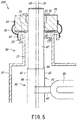
- FIG. 5 is an enlarged view showing the upper part of the hammering rod 40 according to Embodiment 3 and its periphery and corresponds to FIG. 2 of Embodiment 1 and FIG. 4 of Embodiment 2.
- the exhaust heat recovery boiler 300 according to the present embodiment is different in configuration from the exhaust heat recovery boiler 100 according to Embodiment 1 in that the exhaust heat recovery boiler 300 includes two seal plates 70 located between the upper flat surface 24 of the extending portion 20 and the lower surface of the sleeve 50.
- the exhaust heat recovery boiler 300 according to the present embodiment is different in configuration from the exhaust heat recovery boiler 200 according to Embodiment 2 in that in the present embodiment, the seal plates 70 are so-called tapered plates.
- the exhaust heat recovery boiler 300 according to the present embodiment is the same in configuration as the exhaust heat recovery boiler 100 according to Embodiment 1 and the exhaust heat recovery boiler 200 according to Embodiment 2.
- the two seal plates 70 are constituted by a first seal plate 71 and a second seal plate 72.
- the first seal plate 71 is arranged above and adjacent to the second seal plate 72 and is formed such that a thickness of the first seal plate 71 decreases as the first seal plate 71 extends outward in the radial direction.
- the second seal plate 72 is arranged under and adjacent to the first seal plate 71 and is formed such that a thickness of the second seal plate 72 increases as the second seal plate 72 extends outward in the radial direction.
- the seal plates 71 and 72 are not fixed to each other and are not fixed to the lower surface of the sleeve 50 and the upper flat surface 24 of the extending portion 20.
- the first and second seal plates that are so-called tapered plates are inserted between the lower surface of the sleeve 50 and the upper flat surface 24 of the extending portion 20. Therefore, for example, even when the lower surface of the sleeve 50 is inclined relative to the upper flat surface 24 of the extending portion 20, or even when the sleeve 50 rattles, the seal plates 70 (71 and 72) can fit each other. On this account, high seal performance between the hammering rod 40 and the duct casing 10 can be maintained.
Landscapes
- Engineering & Computer Science (AREA)
- Mechanical Engineering (AREA)
- General Engineering & Computer Science (AREA)
- Physics & Mathematics (AREA)
- Thermal Sciences (AREA)
- Chemical & Material Sciences (AREA)
- Combustion & Propulsion (AREA)
- Life Sciences & Earth Sciences (AREA)
- Sustainable Development (AREA)
- Sustainable Energy (AREA)
- Heat-Exchange Devices With Radiators And Conduit Assemblies (AREA)
Abstract
Description
- The present invention relates to an exhaust heat recovery boiler.
- In an exhaust heat recovery boiler, water flowing through a heat exchanger tube is converted into steam by utilizing heat of exhaust gas, and with this, heat energy is recovered from the exhaust gas. When the exhaust gas supplied to the exhaust heat recovery boiler contains a large amount of dust, the dust accumulates on the heat exchanger tube, and this lowers recovery efficiency of the heat energy. As a countermeasure against this, an exhaust heat recovery boiler including a hammering rod is being proposed (see PTL 1, for example). The hammering rod is connected to the heat exchanger tube. By applying impact to the hammering rod from outside, the impact is transferred to the heat exchanger tube, and the dust accumulating on the heat exchanger tube falls. Thus, the recovery efficiency of the heat energy can be prevented from lowering.
- PTL 1: Published
Japanese Translation of PCT Application No. 2018-508739 - In the exhaust heat recovery boiler, the heat exchanger tube is provided in a duct casing through which the exhaust gas flows. In the duct casing, the hammering rod is connected to the heat exchanger tube. Moreover, an upper part of the hammering rod projects to an outside of the duct casing and is strongly hit by an external mechanism. To be specific, since the hammering rod penetrates the duct casing, a seal between the hammering rod and the duct casing needs to be realized.
- Moreover, both of the heat exchanger tube and the duct casing expand by the heat of the exhaust gas. However, since the water flows in the heat exchanger tube, the temperature of the heat exchanger tube does not increase significantly. On the other hand, the temperature of the duct casing increases to a temperature close to the temperature of the exhaust gas. Therefore, the amount of thermal expansion of the duct casing is larger than that of the heat exchanger tube, and the duct casing is displaced relative to the hammering rod. Even when the duct casing is displaced relative to the hammering rod as above, the seal between the hammering rod and the duct casing needs to be maintained.
- The present invention was made under these circumstances, and an object of the present invention is to provide an exhaust heat recovery boiler configured such that even when a duct casing is displaced relative to a hammering rod, high seal performance between the hammering rod and the duct casing can be maintained.
- An exhaust heat recovery boiler according to one aspect of the present invention includes: a duct casing in which exhaust gas flows; a tubular extending portion extending upward from the duct casing; a heat exchanger tube located in the duct casing; a hammering rod connected to the heat exchanger tube in the duct casing and passing through an inside of the extending portion, the hammering rod including an upper part projecting to an outside of the extending portion; and an annular sleeve attached to the upper part of the hammering rod through a packing. The extending portion includes an upper flat surface which is located at an upper end of the extending portion, realizes a seal between the upper flat surface and a lower surface of the sleeve, and is annular and flat.
- According to the exhaust heat recovery boiler, the seal is realized between the lower surface of the sleeve and the upper flat surface of the extending portion. To be specific, since the seal is realized between the surfaces, a contact area is large, and therefore, high seal performance can be obtained. Moreover, when the high-temperature exhaust gas flows in the duct casing, the duct casing is displaced relative to the hammering rod. Therefore, the extending portion extending from the duct casing is displaced relative to the sleeve attached to the hammering rod. As described above, the contact area between the sleeve and the extending portion is large. Therefore, even when the sleeve is displaced relative to the extending portion, high seal performance can be maintained.
- In the above exhaust heat recovery boiler, the upper flat surface of the extending portion may be in surface-contact with the lower surface of the sleeve.
- According to the exhaust heat recovery boiler, since the upper flat surface of the extending portion and the lower surface of the sleeve are in surface-contact with each other, high seal performance between the hammering rod and the duct casing can be maintained although the configuration is simple.
- The exhaust heat recovery boiler according to another aspect may further include one or a plurality of seal plates located between the lower surface of the sleeve and the upper flat surface of the extending portion and formed in an annular shape.
- According to the exhaust heat recovery boiler, the seal between the lower surface of the sleeve and the upper flat surface of the extending portion is realized by using one or a plurality of seal plates. When the extending portion is displaced relative to the sleeve, the seal plates are slightly displaced relative to each other and gradually fit each other. With this, high seal performance between the hammering rod and the duct casing can be maintained.
- The exhaust heat recovery boiler according to yet another aspect may further include a plurality of seal plates located between the lower surface of the sleeve and the upper flat surface of the extending portion and formed in an annular shape. The plurality of seal plates may include a first seal plate having a thickness which decreases as the first seal plate extends outward in a radial direction and a second seal plate arranged adjacent to the first seal plate and having a thickness which increases as the second seal plate extends outward in the radial direction.
- The exhaust heat recovery boiler includes the first and second seal plates that are so-called tapered plates. Therefore, even when the lower surface of the sleeve is inclined relative to the upper flat surface of the extending portion, or even when the sleeve rattles, the seal plates can fit each other. On this account, high seal performance between the hammering rod and the duct casing can be maintained.
- In the above exhaust heat recovery boiler, during a cold state in which the exhaust gas is not flowing in the duct casing, a central axis of the extending portion may be located closer to a middle side of the duct casing than a central axis of the hammering rod.
- According to the exhaust heat recovery boiler, during the cold state, the central axis of the extending portion is located closer to the middle side of the duct casing than the central axis of the hammering rod. Therefore, during the hot state in which the exhaust gas is flowing in the duct casing, the central axis of the extending portion approaches the central axis of the hammering rod. As a result, during the hot state, positional deviation between a central axis of the lower surface of the sleeve and a central axis of the upper flat surface of the extending portion decreases, and therefore, high seal performance between the hammering rod and the duct casing can be maintained.
- In the above exhaust heat recovery boiler, the extending portion may include: a cylindrical main body portion extending upward from the duct casing; and an annular horizontal portion extending outward in a radial direction from an upper end part of the main body portion and including an upper surface constituting the upper flat surface.
- According to the exhaust heat recovery boiler, the upper surface of the horizontal portion extending outward in the radial direction from the upper end part of the main body portion constitutes the upper flat surface of the extending portion. Therefore, the upper flat surface of the extending portion can be easily formed.
- The above exhaust heat recovery boiler may further include a bellows covering a boundary between the sleeve and the extending portion. The extending portion may include an outer wall portion extending downward from a radially outer end part of the horizontal portion. The bellows may include an upper end part fixed to an outer peripheral surface of the sleeve and a lower end part fixed to the outer wall portion of the extending portion.
- Since the exhaust heat recovery boiler includes the bellows covering the boundary between the sleeve and the extending portion, the seal performance between the hammering rod and the duct casing can be improved. In addition, since the lower end part of the bellows is fixed to not the main body portion, which is high in temperature, of the extending portion but the outer wall portion located outside the main body portion in the radial direction, thermal damage of the bellows can be prevented.
- In the above exhaust heat recovery boiler, the hammering rod may include: a circular column portion penetrating the sleeve and having a circular section; a square column portion having a square section, a coupling member being fixed to the square column portion, the heat exchanger tube being coupled to the square column portion through the coupling member; and an intermediate portion located between the circular column portion and the square column portion and formed in such a curved shape that a section of the intermediate portion changes from a circular shape to a square shape as the intermediate portion extends from the circular column portion toward the square column portion.
- According to the exhaust heat recovery boiler, since the portion of the hammering rod which portion penetrates the sleeve has the circular section, the seal between the hammering rod and the sleeve can be easily realized. Moreover, since the portion of the hammering rod to which portion the coupling member is fixed has the square section, the fixing of the coupling member to the hammering rod can be easily performed. In addition, since the hammering rod includes the intermediate portion located between the circular column portion and the square column portion and formed in the curved shape, the dust can be prevented from accumulating at the boundary between the circular column portion and the square column portion.
- As described above, according to the above configuration, the present invention can provide the exhaust heat recovery boiler configured such that even when the duct casing is displaced relative to the hammering rod, high seal performance between the hammering rod and the duct casing can be maintained.
-
-
FIG. 1 is a sectional view showing an exhaust heat recovery boiler according to Embodiment 1. -
FIG. 2 is an enlarged view showing an upper part of a hammering rod shown inFIG. 1 and its periphery. -
FIG. 3 is a horizontal sectional view showing a square column portion of the hammering rod shown inFIG. 1 . -
FIG. 4 is an enlarged view showing the upper part of the hammering rod according to Embodiment 2 and its periphery. -
FIG. 5 is an enlarged view showing the upper part of the hammering rod according to Embodiment 3 and its periphery. - First, an exhaust
heat recovery boiler 100 according to Embodiment 1 will be described with reference toFIGS. 1 to 3 .FIG. 1 is a sectional view showing the exhaustheat recovery boiler 100.FIG. 2 is an enlarged view showing an upper part of a hammering rod shown inFIG. 1 and its periphery.FIG. 2 is a diagram during a cold state in which exhaust gas is not supplied to the exhaustheat recovery boiler 100. - The exhaust
heat recovery boiler 100 is a facility configured to recover heat energy from the exhaust gas. A plurality of exhaustheat recovery boilers 100 according to the present embodiment are provided so as to be stacked on each other in an upper-lower direction. As shown inFIG. 1 , the exhaustheat recovery boiler 100 according to the present embodiment includes aduct casing 10, extendingportions 20,heat exchanger tubes 30, hammeringrods 40, andsleeves 50. Moreover, as shown inFIG. 2 , the exhaustheat recovery boiler 100 according to the present embodiment includes bellows 60. The following will describe these components in order. - The
duct casing 10 is a member constituting part of a duct in which the exhaust gas flows. Upper and lower surfaces of theduct casing 10 are open. Theduct casing 10 is formed in a tubular shape having a substantially rectangular section. In the present embodiment, the exhaust gas flows downward in theduct casing 10. Moreover, the exhaust gas flowing in theduct casing 10 contains a large amount of dust. The exhaust gas of the present embodiment is assumed to be exhaust gas generated in the process of manufacturing cement. However, the exhaust gas is not limited to this. Furthermore, theduct casing 10 includes arecess 11 formed such that an outer surface of theduct casing 10 is concave inward. Therecess 11 is located at an upper portion of one longitudinal end side (left side on a paper surface ofFIG. 1 ) of theduct casing 10, and the below-described extendingportion 20 is provided at therecess 11. - The extending
portion 20 is a tubular member extending upward from theduct casing 10. As described above, the extendingportion 20 is provided at therecess 11 of theduct casing 10. As shown inFIG. 2 , the extendingportion 20 includes a cylindricalmain body portion 21 extending upward from theduct casing 10, an annularhorizontal portion 22 extending outward in a radial direction from an upper end part of themain body portion 21, and a cylindricalouter wall portion 23 extending downward from a radially outer end part of thehorizontal portion 22. An upper surface of thehorizontal portion 22 is an annular flat surface (horizontal surface) and constitutes an upperflat surface 24. The upperflat surface 24 is located at an upper end of the extendingportion 20 and is in surface-contact with a lower surface of the below-describedsleeve 50 to realize a seal between the upperflat surface 24 and the lower surface of thesleeve 50. - The
heat exchanger tubes 30 are located in theduct casing 10, and the exhaust gas flows along outer surfaces of theheat exchanger tubes 30. The exhaustheat recovery boiler 100 according to the present embodiment includes a plurality ofheat exchanger tubes 30, and theheat exchanger tubes 30 are arranged at regular intervals in a width direction (direction vertical to the paper surface ofFIG. 1 ). Each of theheat exchanger tubes 30 extends in a horizontal direction (left-right direction on the paper surface ofFIG. 1 ) while making a turn plural times. Water is supplied to eachheat exchanger tube 30 through awater feed header 31. The water supplied to eachheat exchanger tube 30 is converted into steam by heat energy of the exhaust gas. After the steam is once recovered by asteam header 32, the steam is supplied to a steam turbine (not shown). - Both of the
heat exchanger tube 30 and theduct casing 10 expand by the heat of the exhaust gas. However, since the water flows in theheat exchanger tube 30, the temperature of theheat exchanger tube 30 does not increase significantly. On the other hand, the temperature of theduct casing 10 increases to a temperature close to the temperature of the exhaust gas. Therefore, during a hot state in which the exhaust gas is flowing in theduct casing 10, the thermal expansion of theduct casing 10 is larger than the thermal expansion of theheat exchanger tube 30. Thesteam header 32 to which eachheat exchanger tube 30 is connected is supported by theduct casing 10 through a supportingmember 33. Therefore, in the vicinity of thesteam header 32, theduct casing 10 is hardly displaced relative to theheat exchanger tube 30. On the other hand, in a region (left side on the paper surface ofFIG. 1 ) opposite to a position where thesteam header 32 is provided, theduct casing 10 is relatively largely displaced relative to theheat exchanger tube 30. - The hammering
rod 40 is a member which applies impact to theheat exchanger tubes 30 to make the dust, accumulating on theheat exchanger tubes 30, fall. The hammeringrod 40 is connected to theheat exchanger tubes 30 in theduct casing 10 and passes through an inside of the extendingportion 20. The hammeringrod 40 includes the upper part projecting to an outside of the extendingportion 20. When the upper part of the hammeringrod 40 is hit by an external mechanism, the impact is applied to the hammeringrod 40, and the impact is transferred to eachheat exchanger tube 30. - The hammering
rod 40 includes: acircular column portion 42 including the upper part; asquare column portion 43 including a lower part; and anintermediate portion 44 located between thecircular column portion 42 and thesquare column portion 43, and these portions are integrally formed. Thecircular column portion 42 penetrates the below-describedsleeve 50 and is formed to have a circular section. Since the portion penetrating thesleeve 50 has the circular section as above, the seal (seal by using a below-described packing 51) between thesleeve 50 and the hammeringrod 40 can be realized more easily than when the section has a shape other than the circular shape. - The
square column portion 43 is a portion to which theheat exchanger tubes 30 are connected. Thesquare column portion 43 is located in theduct casing 10.FIG. 3 is a horizontal sectional view showing thesquare column portion 43. As shown inFIG. 3 , thesquare column portion 43 has a square section and includes a pair ofvertical surfaces 45 and a pair ofparallel surfaces 46. Thevertical surfaces 45 are vertical to an extending direction (left-right direction on the paper surface ofFIG. 3 ) of theheat exchanger tube 30, and theparallel surfaces 46 are parallel to the extending direction of theheat exchanger tube 30 and perpendicular to the vertical surfaces 45. - One of the
heat exchanger tubes 30 which are located adjacent to each other in the width direction (upper-lower direction on the paper surface ofFIG. 3 ) is coupled to one of theparallel surfaces 46, and the otherheat exchanger tube 30 is connected to the otherparallel surface 46. Moreover, eachheat exchanger tube 30 is coupled to thesquare column portion 43 through a plate-shapedcoupling member 47. Thecoupling member 47 is fixed to the hammeringrod 40 by welding. In the present embodiment, the section of the portion to which theheat exchanger tube 30 is coupled is square. With this, thecoupling member 47 is easily fixed to the hammeringrod 40, and theheat exchanger tube 30 can be firmly connected to the hammeringrod 40. - As described above, the
intermediate portion 44 is a portion located between thecircular column portion 42 and thesquare column portion 43. Theintermediate portion 44 is formed in such a curved shape that a section of theintermediate portion 44 changes from a circular shape to a square shape as theintermediate portion 44 extends from thecircular column portion 42 toward thesquare column portion 43. If the hammeringrod 40 does not include theintermediate portion 44, the dust accumulates on portions (corner portions and the like) of an upper surface of thesquare column portion 43 which portions protrude from thecircular column portion 42. However, since the hammeringrod 40 includes theintermediate portion 44 in the present embodiment, the dust can be prevented from accumulating on thesquare column portion 43. - Moreover, as shown in
FIG. 2 , during the cold state in which the exhaust gas is not flowing in theduct casing 10, acentral axis 25 of the extendingportion 20 is located closer to a middle side of theduct casing 10 than acentral axis 48 of the hammeringrod 40. As described above, during the hot state in which the exhaust gas is flowing in theduct casing 10, theduct casing 10 is relatively largely displaced relative to theheat exchanger tube 30 in the region opposite to the position where thesteam header 32 is provided. Therefore, although thecentral axis 25 of the extendingportion 20 is not aligned with thecentral axis 48 of the hammeringrod 40 during the cold state, thecentral axis 25 of the extendingportion 20 approaches thecentral axis 48 of the hammeringrod 40 during the hot state. - The
sleeve 50 is a member attached to the upper part (circular column portion 42) of the hammeringrod 40. In other words, the hammeringrod 40 penetrates an inside of thesleeve 50. Thesleeve 50 has an annular shape (cylindrical shape having a certain thickness or more), and the lower surface of thesleeve 50 is formed horizontally. Moreover, thesleeve 50 is attached to the hammeringrod 40 through the packing 51. When impact is applied to the hammeringrod 40, the hammeringrod 40 is displaced relative to thesleeve 50 in the upper-lower direction to some extent. Furthermore, anannular cover 52 is attached to an upper surface of thesleeve 50 so as to cover the packing 51. - In the present embodiment, the lower surface of the
sleeve 50 is in surface-contact with the upperflat surface 24 of the extendingportion 20, and the seal is realized between the lower surface of thesleeve 50 and the upperflat surface 24 of the extendingportion 20. To be specific, in the present embodiment, since the seal is realized between the surfaces, a contact area is large, and therefore, high seal performance can be secured. It should be noted that the lower surface of thesleeve 50 and the upperflat surface 24 of the extendingportion 20 are not fixed to each other, and thesleeve 50 is movable relative to the extendingportion 20 in the horizontal direction. - As described above, during the hot state, in the region opposite to the position where the
steam header 32 is provided, theduct casing 10 is relatively largely displaced relative to theheat exchanger tube 30. Therefore, the extendingportion 20 extending from theduct casing 10 is displaced relative to thesleeve 50 attached to the hammeringrod 40. In the present embodiment, the contact area between thesleeve 50 and the upperflat surface 24 of the extendingportion 20 is large as described above. Therefore, even when the extendingportion 20 is displaced relative to thesleeve 50, high seal performance can be maintained. - The bellows 60 is a member covering a boundary between the extending
portion 20 and thesleeve 50. Since thebellows 60 covers the boundary between the extendingportion 20 and thesleeve 50, the seal performance between the hammeringrod 40 and theduct casing 10 can be improved. An upper end part of thebellows 60 is fixed to an outer peripheral surface of thesleeve 50, and a lower end part of thebellows 60 is fixed to theouter wall portion 23 of the extendingportion 20. Since the lower end part of thebellows 60 is fixed to not themain body portion 21, which is high in temperature, but theouter wall portion 23, thermal damage of the bellows can be prevented. - The bellows 60 is fixed to the outer peripheral surface of the
sleeve 50 and theouter wall portion 23 of the extendingportion 20 by using fixingmembers 61. As the fixingmembers 61, bolts, belts, or the like may be adopted. - Next, an exhaust
heat recovery boiler 200 according to Embodiment 2 will be described with reference toFIG. 4. FIG. 4 is an enlarged view showing the upper part of the hammeringrod 40 according to Embodiment 2 and its periphery and corresponds toFIG. 2 of Embodiment 1. As shown inFIG. 4 , the exhaustheat recovery boiler 200 according to the present embodiment is different in configuration from the exhaustheat recovery boiler 100 according to Embodiment 1 in that the exhaustheat recovery boiler 200 includes twoseal plates 70 located between the lower surface of thesleeve 50 and the upperflat surface 24 of the extendingportion 20. Other than the above, the exhaustheat recovery boiler 200 according to the present embodiment is the same in configuration as the exhaustheat recovery boiler 100 according to Embodiment 1. - Each of the
seal plates 70 is formed in an annular shape and may be made of metal or silicon. Moreover, the exhaustheat recovery boiler 200 of the present embodiment includes twoseal plates 70 but may include only oneseal plate 70 or three ormore seal plates 70. It should be noted that theseal plates 70 are not fixed to each other and are not fixed to the lower surface of thesleeve 50 and the upperflat surface 24 of the extendingportion 20. - As above, in the present embodiment, the seal between the lower surface of the
sleeve 50 and the upperflat surface 24 of the extendingportion 20 is realized by using theseal plates 70. When the extendingportion 20 is displaced relative to thesleeve 50 during the hot state, theseal plates 70 are slightly displaced relative to each other and gradually fit each other. With this, high seal performance between the hammeringrod 40 and theduct casing 10 can be maintained. - Next, an exhaust
heat recovery boiler 300 according to Embodiment 3 will be described with reference toFIG. 5. FIG. 5 is an enlarged view showing the upper part of the hammeringrod 40 according to Embodiment 3 and its periphery and corresponds toFIG. 2 of Embodiment 1 andFIG. 4 of Embodiment 2. As shown inFIG. 5 , as with Embodiment 2, the exhaustheat recovery boiler 300 according to the present embodiment is different in configuration from the exhaustheat recovery boiler 100 according to Embodiment 1 in that the exhaustheat recovery boiler 300 includes twoseal plates 70 located between the upperflat surface 24 of the extendingportion 20 and the lower surface of thesleeve 50. It should be noted that the exhaustheat recovery boiler 300 according to the present embodiment is different in configuration from the exhaustheat recovery boiler 200 according to Embodiment 2 in that in the present embodiment, theseal plates 70 are so-called tapered plates. Other than the above, the exhaustheat recovery boiler 300 according to the present embodiment is the same in configuration as the exhaustheat recovery boiler 100 according to Embodiment 1 and the exhaustheat recovery boiler 200 according to Embodiment 2. - In the present embodiment, the two
seal plates 70 are constituted by a first seal plate 71 and a second seal plate 72. The first seal plate 71 is arranged above and adjacent to the second seal plate 72 and is formed such that a thickness of the first seal plate 71 decreases as the first seal plate 71 extends outward in the radial direction. On the other hand, the second seal plate 72 is arranged under and adjacent to the first seal plate 71 and is formed such that a thickness of the second seal plate 72 increases as the second seal plate 72 extends outward in the radial direction. It should be noted that the seal plates 71 and 72 are not fixed to each other and are not fixed to the lower surface of thesleeve 50 and the upperflat surface 24 of the extendingportion 20. - As above, in the present embodiment, the first and second seal plates that are so-called tapered plates are inserted between the lower surface of the
sleeve 50 and the upperflat surface 24 of the extendingportion 20. Therefore, for example, even when the lower surface of thesleeve 50 is inclined relative to the upperflat surface 24 of the extendingportion 20, or even when thesleeve 50 rattles, the seal plates 70 (71 and 72) can fit each other. On this account, high seal performance between the hammeringrod 40 and theduct casing 10 can be maintained. -
- 10
- duct casing
- 20
- extending portion
- 21
- main body portion
- 22
- horizontal portion
- 23
- outer wall portion
- 24
- upper flat surface
- 25
- central axis (extending portion)
- 30
- heat exchanger tube
- 40
- hammering rod
- 42
- circular column portion
- 43
- square column portion
- 44
- intermediate portion
- 47
- coupling member
- 48
- central axis (hammering rod)
- 50
- sleeve
- 51
- packing
- 60
- bellows
- 70
- seal plate
- 71
- first seal plate
- 72
- second seal plate
- 100, 200, 300
- exhaust heat recovery boiler
Claims (8)
- An exhaust heat recovery boiler comprising:a duct casing in which exhaust gas flows;a tubular extending portion extending upward from the duct casing;a heat exchanger tube located in the duct casing;a hammering rod connected to the heat exchanger tube in the duct casing and passing through an inside of the extending portion, the hammering rod including an upper part projecting to an outside of the extending portion; andan annular sleeve attached to the upper part of the hammering rod through a packing, whereinthe extending portion includes an upper flat surface which is located at an upper end of the extending portion, realizes a seal between the upper flat surface and a lower surface of the sleeve, and is annular and flat.
- The exhaust heat recovery boiler according to claim 1, wherein the upper flat surface of the extending portion is in surface-contact with the lower surface of the sleeve.
- The exhaust heat recovery boiler according to claim 1, further comprising one or a plurality of seal plates located between the lower surface of the sleeve and the upper flat surface of the extending portion and formed in an annular shape.
- The exhaust heat recovery boiler according to claim 1, further comprising a plurality of seal plates located between the lower surface of the sleeve and the upper flat surface of the extending portion and formed in an annular shape, whereinthe plurality of seal plates includea first seal plate having a thickness which decreases as the first seal plate extends outward in a radial direction anda second seal plate arranged adjacent to the first seal plate and having a thickness which increases as the second seal plate extends outward in the radial direction.
- The exhaust heat recovery boiler according to any one of claims 1 to 4, wherein during a cold state in which the exhaust gas is not flowing in the duct casing, a central axis of the extending portion is located closer to a middle side of the duct casing than a central axis of the hammering rod.
- The exhaust heat recovery boiler according to any one of claims 1 to 5, wherein the extending portion includes:a cylindrical main body portion extending upward from the duct casing; andan annular horizontal portion extending outward in a radial direction from an upper end part of the main body portion and including an upper surface constituting the upper flat surface.
- The exhaust heat recovery boiler according to claim 6, further comprising a bellows covering a boundary between the sleeve and the extending portion, wherein:the extending portion includes an outer wall portion extending downward from a radially outer end part of the horizontal portion; andthe bellows includes an upper end part fixed to an outer peripheral surface of the sleeve and a lower end part fixed to the outer wall portion of the extending portion.
- The exhaust heat recovery boiler according to any one of claims 1 to 7, wherein the hammering rod includes:a circular column portion penetrating the sleeve and having a circular section;a square column portion having a square section, a coupling member being fixed to the square column portion, the heat exchanger tube being coupled to the square column portion through the coupling member; andan intermediate portion located between the circular column portion and the square column portion and formed in such a curved shape that a section of the intermediate portion changes from a circular shape to a square shape as the intermediate portion extends from the circular column portion toward the square column portion.
Applications Claiming Priority (2)
| Application Number | Priority Date | Filing Date | Title |
|---|---|---|---|
| CN201811451385.8A CN111256099B (en) | 2018-11-30 | 2018-11-30 | Waste heat recovery boiler |
| PCT/JP2019/004989 WO2020110327A1 (en) | 2018-11-30 | 2019-02-13 | Waste heat recovery |
Publications (3)
| Publication Number | Publication Date |
|---|---|
| EP3889500A1 true EP3889500A1 (en) | 2021-10-06 |
| EP3889500A4 EP3889500A4 (en) | 2022-09-07 |
| EP3889500B1 EP3889500B1 (en) | 2024-10-02 |
Family
ID=70852743
Family Applications (1)
| Application Number | Title | Priority Date | Filing Date |
|---|---|---|---|
| EP19889456.0A Active EP3889500B1 (en) | 2018-11-30 | 2019-02-13 | Exhaust heat recovery boiler |
Country Status (5)
| Country | Link |
|---|---|
| US (1) | US11802744B2 (en) |
| EP (1) | EP3889500B1 (en) |
| JP (1) | JP7288459B2 (en) |
| CN (1) | CN111256099B (en) |
| WO (1) | WO2020110327A1 (en) |
Families Citing this family (1)
| Publication number | Priority date | Publication date | Assignee | Title |
|---|---|---|---|---|
| CN114543577B (en) * | 2022-03-07 | 2024-02-13 | 义煤集团宜阳义络煤业有限责任公司 | A mine return air waste heat recovery system |
Family Cites Families (21)
| Publication number | Priority date | Publication date | Assignee | Title |
|---|---|---|---|---|
| JPS6039665Y2 (en) | 1983-01-18 | 1985-11-28 | 川崎重工業株式会社 | waste heat boiler |
| US4497282A (en) * | 1983-11-23 | 1985-02-05 | Neundorfer, Inc. | Apparatus for deslagging steam generator tubes |
| JPS6135287U (en) * | 1984-08-03 | 1986-03-04 | 日東工器株式会社 | rubber gasket |
| JPH07167403A (en) * | 1993-12-14 | 1995-07-04 | Mitsubishi Heavy Ind Ltd | Furnace wall device |
| JP3562014B2 (en) | 1995-03-16 | 2004-09-08 | 大同特殊鋼株式会社 | Sealing equipment for welding |
| JP3657198B2 (en) * | 2001-01-26 | 2005-06-08 | 川崎重工業株式会社 | Dust removal device for heat exchanger surface of coal gasifier |
| CN2735089Y (en) * | 2004-06-02 | 2005-10-19 | 上海万安企业总公司 | Corrugated pipe sealing arrangement |
| CN101592341A (en) * | 2006-03-31 | 2009-12-02 | 杭州锅炉集团股份有限公司 | Ash removal equipment for flapping exhaust heat boiler |
| EP2119997B1 (en) * | 2008-05-13 | 2011-12-21 | Hitachi Zosen Inova AG | Method for checking a knocking device |
| CN101858590A (en) * | 2008-09-02 | 2010-10-13 | 安徽海螺川崎工程有限公司 | Rapping device and rapping method for heated tube suspended structure of kiln tail waste heat boiler of cement kiln |
| US20130320266A1 (en) * | 2010-09-23 | 2013-12-05 | Thomas Paul Von Kossak-Glowczewski | Gasification reactor and process |
| US8888413B2 (en) * | 2010-11-09 | 2014-11-18 | Hubbell Incorporated | Transition coupling between cylindrical drive shaft and helical pile shaft |
| JP5434892B2 (en) * | 2010-11-30 | 2014-03-05 | 住友金属鉱山株式会社 | Shielding equipment for smelting furnace waste heat recovery boiler |
| CN202813403U (en) * | 2012-09-12 | 2013-03-20 | 陕西鼓风机集团西安锅炉有限责任公司(西安特种汽车厂) | Mechanical vibrating device of low temperature waste heat boiler |
| CN203363187U (en) * | 2013-07-20 | 2013-12-25 | 山东东华水泥有限公司 | Auxiliary sealing device of boiler vibrating mechanism |
| ES2955103T3 (en) | 2015-02-12 | 2023-11-28 | Anhui Conch Kawasaki Engineering Company Ltd | heat recovery boiler |
| US10907822B2 (en) | 2015-02-12 | 2021-02-02 | Anhui Conch Kawasaki Engineering Company Limited | Waste heat boiler |
| CN104930214A (en) * | 2015-07-15 | 2015-09-23 | 洞头华夏阀门有限公司 | Rapid installation type high pressure floating ball valve |
| CN205606607U (en) * | 2016-05-11 | 2016-09-28 | 南通万达锅炉有限公司 | Exhaust -heat boiler machinery rapping device |
| CN106524198A (en) * | 2016-11-22 | 2017-03-22 | 无锡锡东能源科技有限公司 | Hammering machine |
| CN209524490U (en) * | 2018-11-30 | 2019-10-22 | 川崎重工业株式会社 | Waste Heat Recovery Boiler |
-
2018
- 2018-11-30 CN CN201811451385.8A patent/CN111256099B/en active Active
-
2019
- 2019-02-13 EP EP19889456.0A patent/EP3889500B1/en active Active
- 2019-02-13 US US17/298,866 patent/US11802744B2/en active Active
- 2019-02-13 JP JP2020557534A patent/JP7288459B2/en active Active
- 2019-02-13 WO PCT/JP2019/004989 patent/WO2020110327A1/en not_active Ceased
Also Published As
| Publication number | Publication date |
|---|---|
| EP3889500B1 (en) | 2024-10-02 |
| US20220034609A1 (en) | 2022-02-03 |
| JP7288459B2 (en) | 2023-06-07 |
| JPWO2020110327A1 (en) | 2021-09-27 |
| US11802744B2 (en) | 2023-10-31 |
| CN111256099A (en) | 2020-06-09 |
| CN111256099B (en) | 2021-11-30 |
| WO2020110327A1 (en) | 2020-06-04 |
| EP3889500A4 (en) | 2022-09-07 |
Similar Documents
| Publication | Publication Date | Title |
|---|---|---|
| RU2742159C1 (en) | Anti-erosion device for shell-and-tube equipment | |
| US8572847B2 (en) | Tube support system for nuclear steam generators | |
| JP6453323B2 (en) | Replacement method of boiler and its heat transfer tube | |
| US9347662B2 (en) | Tube support system for nuclear steam generators | |
| US20080104838A1 (en) | Anti-vibration support for steam generator heat transfer tubes and method for making same | |
| EP3889500B1 (en) | Exhaust heat recovery boiler | |
| JP2013092260A (en) | Waste heat boiler | |
| CN209524490U (en) | Waste Heat Recovery Boiler | |
| KR100942657B1 (en) | Mechanical sleeve type expansion joint of heat recovery system generator | |
| RU2673974C2 (en) | Long-life heat recovery steam generator device with use of internal stiffeners | |
| EP3273162B1 (en) | Thermal device, its use, and method for heating a heat transfer medium | |
| KR100432088B1 (en) | A waste heat recovery boiler with fin tube sliding guides | |
| KR101529110B1 (en) | Boiler | |
| KR102781933B1 (en) | Connection tube support of waste heat recovery boiler and waste heat recovery boiler including the same | |
| JP5489837B2 (en) | Steam generator | |
| US20200284428A1 (en) | System and method for accomodating thermal displacement in a power generation plant | |
| AU2003278171A1 (en) | Method for producing a continuous steam generator and continuous steam generator | |
| KR102450401B1 (en) | heat exchanger | |
| JP5728314B2 (en) | Heat exchanger | |
| KR20070025272A (en) | Water-cooled cyclone for circulating fluidized bed boiler | |
| JPH04108107U (en) | boiler furnace wall |
Legal Events
| Date | Code | Title | Description |
|---|---|---|---|
| STAA | Information on the status of an ep patent application or granted ep patent |
Free format text: STATUS: THE INTERNATIONAL PUBLICATION HAS BEEN MADE |
|
| PUAI | Public reference made under article 153(3) epc to a published international application that has entered the european phase |
Free format text: ORIGINAL CODE: 0009012 |
|
| STAA | Information on the status of an ep patent application or granted ep patent |
Free format text: STATUS: REQUEST FOR EXAMINATION WAS MADE |
|
| 17P | Request for examination filed |
Effective date: 20210422 |
|
| AK | Designated contracting states |
Kind code of ref document: A1 Designated state(s): AL AT BE BG CH CY CZ DE DK EE ES FI FR GB GR HR HU IE IS IT LI LT LU LV MC MK MT NL NO PL PT RO RS SE SI SK SM TR |
|
| DAV | Request for validation of the european patent (deleted) | ||
| DAX | Request for extension of the european patent (deleted) | ||
| A4 | Supplementary search report drawn up and despatched |
Effective date: 20220805 |
|
| RIC1 | Information provided on ipc code assigned before grant |
Ipc: F28G 1/08 20060101ALI20220801BHEP Ipc: F23J 15/06 20060101ALI20220801BHEP Ipc: F22B 1/18 20060101AFI20220801BHEP |
|
| GRAP | Despatch of communication of intention to grant a patent |
Free format text: ORIGINAL CODE: EPIDOSNIGR1 |
|
| STAA | Information on the status of an ep patent application or granted ep patent |
Free format text: STATUS: GRANT OF PATENT IS INTENDED |
|
| RIC1 | Information provided on ipc code assigned before grant |
Ipc: F28G 1/08 20060101ALI20240612BHEP Ipc: F23J 15/06 20060101ALI20240612BHEP Ipc: F22B 1/18 20060101AFI20240612BHEP |
|
| INTG | Intention to grant announced |
Effective date: 20240701 |
|
| GRAS | Grant fee paid |
Free format text: ORIGINAL CODE: EPIDOSNIGR3 |
|
| GRAA | (expected) grant |
Free format text: ORIGINAL CODE: 0009210 |
|
| STAA | Information on the status of an ep patent application or granted ep patent |
Free format text: STATUS: THE PATENT HAS BEEN GRANTED |
|
| AK | Designated contracting states |
Kind code of ref document: B1 Designated state(s): AL AT BE BG CH CY CZ DE DK EE ES FI FR GB GR HR HU IE IS IT LI LT LU LV MC MK MT NL NO PL PT RO RS SE SI SK SM TR |
|
| REG | Reference to a national code |
Ref country code: GB Ref legal event code: FG4D |
|
| REG | Reference to a national code |
Ref country code: CH Ref legal event code: EP |
|
| REG | Reference to a national code |
Ref country code: IE Ref legal event code: FG4D |
|
| REG | Reference to a national code |
Ref country code: DE Ref legal event code: R096 Ref document number: 602019059874 Country of ref document: DE |
|
| REG | Reference to a national code |
Ref country code: LT Ref legal event code: MG9D |
|
| REG | Reference to a national code |
Ref country code: NL Ref legal event code: MP Effective date: 20241002 |
|
| REG | Reference to a national code |
Ref country code: AT Ref legal event code: MK05 Ref document number: 1728750 Country of ref document: AT Kind code of ref document: T Effective date: 20241002 |
|
| PG25 | Lapsed in a contracting state [announced via postgrant information from national office to epo] |
Ref country code: NL Free format text: LAPSE BECAUSE OF FAILURE TO SUBMIT A TRANSLATION OF THE DESCRIPTION OR TO PAY THE FEE WITHIN THE PRESCRIBED TIME-LIMIT Effective date: 20241002 |
|
| PG25 | Lapsed in a contracting state [announced via postgrant information from national office to epo] |
Ref country code: NL Free format text: LAPSE BECAUSE OF FAILURE TO SUBMIT A TRANSLATION OF THE DESCRIPTION OR TO PAY THE FEE WITHIN THE PRESCRIBED TIME-LIMIT Effective date: 20241002 |
|
| PG25 | Lapsed in a contracting state [announced via postgrant information from national office to epo] |
Ref country code: HR Free format text: LAPSE BECAUSE OF FAILURE TO SUBMIT A TRANSLATION OF THE DESCRIPTION OR TO PAY THE FEE WITHIN THE PRESCRIBED TIME-LIMIT Effective date: 20241002 Ref country code: IS Free format text: LAPSE BECAUSE OF FAILURE TO SUBMIT A TRANSLATION OF THE DESCRIPTION OR TO PAY THE FEE WITHIN THE PRESCRIBED TIME-LIMIT Effective date: 20250202 Ref country code: PT Free format text: LAPSE BECAUSE OF FAILURE TO SUBMIT A TRANSLATION OF THE DESCRIPTION OR TO PAY THE FEE WITHIN THE PRESCRIBED TIME-LIMIT Effective date: 20250203 |
|
| PG25 | Lapsed in a contracting state [announced via postgrant information from national office to epo] |
Ref country code: FI Free format text: LAPSE BECAUSE OF FAILURE TO SUBMIT A TRANSLATION OF THE DESCRIPTION OR TO PAY THE FEE WITHIN THE PRESCRIBED TIME-LIMIT Effective date: 20241002 |
|
| PG25 | Lapsed in a contracting state [announced via postgrant information from national office to epo] |
Ref country code: BG Free format text: LAPSE BECAUSE OF FAILURE TO SUBMIT A TRANSLATION OF THE DESCRIPTION OR TO PAY THE FEE WITHIN THE PRESCRIBED TIME-LIMIT Effective date: 20241002 |
|
| PG25 | Lapsed in a contracting state [announced via postgrant information from national office to epo] |
Ref country code: ES Free format text: LAPSE BECAUSE OF FAILURE TO SUBMIT A TRANSLATION OF THE DESCRIPTION OR TO PAY THE FEE WITHIN THE PRESCRIBED TIME-LIMIT Effective date: 20241002 |
|
| PG25 | Lapsed in a contracting state [announced via postgrant information from national office to epo] |
Ref country code: NO Free format text: LAPSE BECAUSE OF FAILURE TO SUBMIT A TRANSLATION OF THE DESCRIPTION OR TO PAY THE FEE WITHIN THE PRESCRIBED TIME-LIMIT Effective date: 20250102 |
|
| PG25 | Lapsed in a contracting state [announced via postgrant information from national office to epo] |
Ref country code: GR Free format text: LAPSE BECAUSE OF FAILURE TO SUBMIT A TRANSLATION OF THE DESCRIPTION OR TO PAY THE FEE WITHIN THE PRESCRIBED TIME-LIMIT Effective date: 20250103 Ref country code: AT Free format text: LAPSE BECAUSE OF FAILURE TO SUBMIT A TRANSLATION OF THE DESCRIPTION OR TO PAY THE FEE WITHIN THE PRESCRIBED TIME-LIMIT Effective date: 20241002 Ref country code: LV Free format text: LAPSE BECAUSE OF FAILURE TO SUBMIT A TRANSLATION OF THE DESCRIPTION OR TO PAY THE FEE WITHIN THE PRESCRIBED TIME-LIMIT Effective date: 20241002 |
|
| PG25 | Lapsed in a contracting state [announced via postgrant information from national office to epo] |
Ref country code: PL Free format text: LAPSE BECAUSE OF FAILURE TO SUBMIT A TRANSLATION OF THE DESCRIPTION OR TO PAY THE FEE WITHIN THE PRESCRIBED TIME-LIMIT Effective date: 20241002 Ref country code: CZ Free format text: LAPSE BECAUSE OF FAILURE TO SUBMIT A TRANSLATION OF THE DESCRIPTION OR TO PAY THE FEE WITHIN THE PRESCRIBED TIME-LIMIT Effective date: 20241002 |
|
| PG25 | Lapsed in a contracting state [announced via postgrant information from national office to epo] |
Ref country code: RS Free format text: LAPSE BECAUSE OF FAILURE TO SUBMIT A TRANSLATION OF THE DESCRIPTION OR TO PAY THE FEE WITHIN THE PRESCRIBED TIME-LIMIT Effective date: 20250102 |
|
| PG25 | Lapsed in a contracting state [announced via postgrant information from national office to epo] |
Ref country code: SM Free format text: LAPSE BECAUSE OF FAILURE TO SUBMIT A TRANSLATION OF THE DESCRIPTION OR TO PAY THE FEE WITHIN THE PRESCRIBED TIME-LIMIT Effective date: 20241002 |
|
| REG | Reference to a national code |
Ref country code: DE Ref legal event code: R097 Ref document number: 602019059874 Country of ref document: DE |
|
| PG25 | Lapsed in a contracting state [announced via postgrant information from national office to epo] |
Ref country code: DK Free format text: LAPSE BECAUSE OF FAILURE TO SUBMIT A TRANSLATION OF THE DESCRIPTION OR TO PAY THE FEE WITHIN THE PRESCRIBED TIME-LIMIT Effective date: 20241002 |
|
| PG25 | Lapsed in a contracting state [announced via postgrant information from national office to epo] |
Ref country code: EE Free format text: LAPSE BECAUSE OF FAILURE TO SUBMIT A TRANSLATION OF THE DESCRIPTION OR TO PAY THE FEE WITHIN THE PRESCRIBED TIME-LIMIT Effective date: 20241002 |
|
| PG25 | Lapsed in a contracting state [announced via postgrant information from national office to epo] |
Ref country code: RO Free format text: LAPSE BECAUSE OF FAILURE TO SUBMIT A TRANSLATION OF THE DESCRIPTION OR TO PAY THE FEE WITHIN THE PRESCRIBED TIME-LIMIT Effective date: 20241002 |
|
| PG25 | Lapsed in a contracting state [announced via postgrant information from national office to epo] |
Ref country code: SK Free format text: LAPSE BECAUSE OF FAILURE TO SUBMIT A TRANSLATION OF THE DESCRIPTION OR TO PAY THE FEE WITHIN THE PRESCRIBED TIME-LIMIT Effective date: 20241002 |
|
| PLBE | No opposition filed within time limit |
Free format text: ORIGINAL CODE: 0009261 |
|
| STAA | Information on the status of an ep patent application or granted ep patent |
Free format text: STATUS: NO OPPOSITION FILED WITHIN TIME LIMIT |
|
| PG25 | Lapsed in a contracting state [announced via postgrant information from national office to epo] |
Ref country code: SE Free format text: LAPSE BECAUSE OF FAILURE TO SUBMIT A TRANSLATION OF THE DESCRIPTION OR TO PAY THE FEE WITHIN THE PRESCRIBED TIME-LIMIT Effective date: 20241002 |
|
| 26N | No opposition filed |
Effective date: 20250703 |
|
| PG25 | Lapsed in a contracting state [announced via postgrant information from national office to epo] |
Ref country code: MC Free format text: LAPSE BECAUSE OF FAILURE TO SUBMIT A TRANSLATION OF THE DESCRIPTION OR TO PAY THE FEE WITHIN THE PRESCRIBED TIME-LIMIT Effective date: 20241002 |
|
| REG | Reference to a national code |
Ref country code: CH Ref legal event code: PL |
|
| PG25 | Lapsed in a contracting state [announced via postgrant information from national office to epo] |
Ref country code: LU Free format text: LAPSE BECAUSE OF NON-PAYMENT OF DUE FEES Effective date: 20250213 |
|
| PG25 | Lapsed in a contracting state [announced via postgrant information from national office to epo] |
Ref country code: CH Free format text: LAPSE BECAUSE OF NON-PAYMENT OF DUE FEES Effective date: 20250228 |
|
| GBPC | Gb: european patent ceased through non-payment of renewal fee |
Effective date: 20250213 |
|
| REG | Reference to a national code |
Ref country code: BE Ref legal event code: MM Effective date: 20250228 |
|
| PG25 | Lapsed in a contracting state [announced via postgrant information from national office to epo] |
Ref country code: GB Free format text: LAPSE BECAUSE OF NON-PAYMENT OF DUE FEES Effective date: 20250213 |
|
| PG25 | Lapsed in a contracting state [announced via postgrant information from national office to epo] |
Ref country code: FR Free format text: LAPSE BECAUSE OF NON-PAYMENT OF DUE FEES Effective date: 20250228 |
|
| PG25 | Lapsed in a contracting state [announced via postgrant information from national office to epo] |
Ref country code: BE Free format text: LAPSE BECAUSE OF NON-PAYMENT OF DUE FEES Effective date: 20250228 |
|
| PG25 | Lapsed in a contracting state [announced via postgrant information from national office to epo] |
Ref country code: IE Free format text: LAPSE BECAUSE OF NON-PAYMENT OF DUE FEES Effective date: 20250213 |
|
| PGFP | Annual fee paid to national office [announced via postgrant information from national office to epo] |
Ref country code: DE Payment date: 20260209 Year of fee payment: 8 |
|
| PGFP | Annual fee paid to national office [announced via postgrant information from national office to epo] |
Ref country code: IT Payment date: 20260123 Year of fee payment: 8 |
|
| PG25 | Lapsed in a contracting state [announced via postgrant information from national office to epo] |
Ref country code: CY Free format text: LAPSE BECAUSE OF FAILURE TO SUBMIT A TRANSLATION OF THE DESCRIPTION OR TO PAY THE FEE WITHIN THE PRESCRIBED TIME-LIMIT Effective date: 20241002 |
|
| PG25 | Lapsed in a contracting state [announced via postgrant information from national office to epo] |
Ref country code: LT Free format text: LAPSE BECAUSE OF FAILURE TO SUBMIT A TRANSLATION OF THE DESCRIPTION OR TO PAY THE FEE WITHIN THE PRESCRIBED TIME-LIMIT Effective date: 20241002 |
|
| PG25 | Lapsed in a contracting state [announced via postgrant information from national office to epo] |
Ref country code: TR Free format text: LAPSE BECAUSE OF FAILURE TO SUBMIT A TRANSLATION OF THE DESCRIPTION OR TO PAY THE FEE WITHIN THE PRESCRIBED TIME-LIMIT Effective date: 20241002 |