EP3889395B1 - Gasturbinenmotor mit partikelaufnahme- und akkumulationssensorsystem und -verfahren - Google Patents
Gasturbinenmotor mit partikelaufnahme- und akkumulationssensorsystem und -verfahren Download PDFInfo
- Publication number
- EP3889395B1 EP3889395B1 EP20166876.1A EP20166876A EP3889395B1 EP 3889395 B1 EP3889395 B1 EP 3889395B1 EP 20166876 A EP20166876 A EP 20166876A EP 3889395 B1 EP3889395 B1 EP 3889395B1
- Authority
- EP
- European Patent Office
- Prior art keywords
- particulate
- turbine engine
- gas turbine
- type
- sensor
- Prior art date
- Legal status (The legal status is an assumption and is not a legal conclusion. Google has not performed a legal analysis and makes no representation as to the accuracy of the status listed.)
- Active
Links
Images



Classifications
-
- F—MECHANICAL ENGINEERING; LIGHTING; HEATING; WEAPONS; BLASTING
- F01—MACHINES OR ENGINES IN GENERAL; ENGINE PLANTS IN GENERAL; STEAM ENGINES
- F01D—NON-POSITIVE DISPLACEMENT MACHINES OR ENGINES, e.g. STEAM TURBINES
- F01D21/00—Shutting-down of machines or engines, e.g. in emergency; Regulating, controlling, or safety means not otherwise provided for
- F01D21/003—Arrangements for testing or measuring
-
- B—PERFORMING OPERATIONS; TRANSPORTING
- B64—AIRCRAFT; AVIATION; COSMONAUTICS
- B64D—EQUIPMENT FOR FITTING IN OR TO AIRCRAFT; FLIGHT SUITS; PARACHUTES; ARRANGEMENT OR MOUNTING OF POWER PLANTS OR PROPULSION TRANSMISSIONS IN AIRCRAFT
- B64D45/00—Aircraft indicators or protectors not otherwise provided for
-
- F—MECHANICAL ENGINEERING; LIGHTING; HEATING; WEAPONS; BLASTING
- F01—MACHINES OR ENGINES IN GENERAL; ENGINE PLANTS IN GENERAL; STEAM ENGINES
- F01D—NON-POSITIVE DISPLACEMENT MACHINES OR ENGINES, e.g. STEAM TURBINES
- F01D17/00—Regulating or controlling by varying flow
- F01D17/02—Arrangement of sensing elements
-
- G—PHYSICS
- G01—MEASURING; TESTING
- G01M—TESTING STATIC OR DYNAMIC BALANCE OF MACHINES OR STRUCTURES; TESTING OF STRUCTURES OR APPARATUS, NOT OTHERWISE PROVIDED FOR
- G01M15/00—Testing of engines
- G01M15/14—Testing gas-turbine engines or jet-propulsion engines
-
- G—PHYSICS
- G01—MEASURING; TESTING
- G01N—INVESTIGATING OR ANALYSING MATERIALS BY DETERMINING THEIR CHEMICAL OR PHYSICAL PROPERTIES
- G01N15/00—Investigating characteristics of particles; Investigating permeability, pore-volume or surface-area of porous materials
- G01N15/06—Investigating concentration of particle suspensions
-
- F—MECHANICAL ENGINEERING; LIGHTING; HEATING; WEAPONS; BLASTING
- F05—INDEXING SCHEMES RELATING TO ENGINES OR PUMPS IN VARIOUS SUBCLASSES OF CLASSES F01-F04
- F05D—INDEXING SCHEME FOR ASPECTS RELATING TO NON-POSITIVE-DISPLACEMENT MACHINES OR ENGINES, GAS-TURBINES OR JET-PROPULSION PLANTS
- F05D2220/00—Application
- F05D2220/30—Application in turbines
- F05D2220/32—Application in turbines in gas turbines
- F05D2220/323—Application in turbines in gas turbines for aircraft propulsion, e.g. jet engines
-
- F—MECHANICAL ENGINEERING; LIGHTING; HEATING; WEAPONS; BLASTING
- F05—INDEXING SCHEMES RELATING TO ENGINES OR PUMPS IN VARIOUS SUBCLASSES OF CLASSES F01-F04
- F05D—INDEXING SCHEME FOR ASPECTS RELATING TO NON-POSITIVE-DISPLACEMENT MACHINES OR ENGINES, GAS-TURBINES OR JET-PROPULSION PLANTS
- F05D2260/00—Function
- F05D2260/60—Fluid transfer
- F05D2260/607—Preventing clogging or obstruction of flow paths by dirt, dust, or foreign particles
-
- F—MECHANICAL ENGINEERING; LIGHTING; HEATING; WEAPONS; BLASTING
- F05—INDEXING SCHEMES RELATING TO ENGINES OR PUMPS IN VARIOUS SUBCLASSES OF CLASSES F01-F04
- F05D—INDEXING SCHEME FOR ASPECTS RELATING TO NON-POSITIVE-DISPLACEMENT MACHINES OR ENGINES, GAS-TURBINES OR JET-PROPULSION PLANTS
- F05D2260/00—Function
- F05D2260/80—Diagnostics
-
- F—MECHANICAL ENGINEERING; LIGHTING; HEATING; WEAPONS; BLASTING
- F05—INDEXING SCHEMES RELATING TO ENGINES OR PUMPS IN VARIOUS SUBCLASSES OF CLASSES F01-F04
- F05D—INDEXING SCHEME FOR ASPECTS RELATING TO NON-POSITIVE-DISPLACEMENT MACHINES OR ENGINES, GAS-TURBINES OR JET-PROPULSION PLANTS
- F05D2260/00—Function
- F05D2260/82—Forecasts
- F05D2260/821—Parameter estimation or prediction
-
- F—MECHANICAL ENGINEERING; LIGHTING; HEATING; WEAPONS; BLASTING
- F05—INDEXING SCHEMES RELATING TO ENGINES OR PUMPS IN VARIOUS SUBCLASSES OF CLASSES F01-F04
- F05D—INDEXING SCHEME FOR ASPECTS RELATING TO NON-POSITIVE-DISPLACEMENT MACHINES OR ENGINES, GAS-TURBINES OR JET-PROPULSION PLANTS
- F05D2270/00—Control
- F05D2270/01—Purpose of the control system
- F05D2270/11—Purpose of the control system to prolong engine life
-
- F—MECHANICAL ENGINEERING; LIGHTING; HEATING; WEAPONS; BLASTING
- F05—INDEXING SCHEMES RELATING TO ENGINES OR PUMPS IN VARIOUS SUBCLASSES OF CLASSES F01-F04
- F05D—INDEXING SCHEME FOR ASPECTS RELATING TO NON-POSITIVE-DISPLACEMENT MACHINES OR ENGINES, GAS-TURBINES OR JET-PROPULSION PLANTS
- F05D2270/00—Control
- F05D2270/80—Devices generating input signals, e.g. transducers, sensors, cameras or strain gauges
-
- G—PHYSICS
- G01—MEASURING; TESTING
- G01N—INVESTIGATING OR ANALYSING MATERIALS BY DETERMINING THEIR CHEMICAL OR PHYSICAL PROPERTIES
- G01N15/00—Investigating characteristics of particles; Investigating permeability, pore-volume or surface-area of porous materials
- G01N2015/0042—Investigating dispersion of solids
- G01N2015/0046—Investigating dispersion of solids in gas, e.g. smoke
-
- Y—GENERAL TAGGING OF NEW TECHNOLOGICAL DEVELOPMENTS; GENERAL TAGGING OF CROSS-SECTIONAL TECHNOLOGIES SPANNING OVER SEVERAL SECTIONS OF THE IPC; TECHNICAL SUBJECTS COVERED BY FORMER USPC CROSS-REFERENCE ART COLLECTIONS [XRACs] AND DIGESTS
- Y02—TECHNOLOGIES OR APPLICATIONS FOR MITIGATION OR ADAPTATION AGAINST CLIMATE CHANGE
- Y02T—CLIMATE CHANGE MITIGATION TECHNOLOGIES RELATED TO TRANSPORTATION
- Y02T50/00—Aeronautics or air transport
- Y02T50/60—Efficient propulsion technologies, e.g. for aircraft
Definitions
- the present invention generally relates to gas turbine engines, and more particularly relates to a system and method for sensing particulate ingestion and accumulation.
- Aircraft turbine engines such as a turbofan gas turbine engine, may be exposed to numerous and varied environmental conditions both on the ground and in flight.
- the engine may be exposed to supercooled liquid droplets, ice crystals, sand, dust, or volcanic ash.
- Such exposure may result in accumulation of ice or other particulate at various locations on or within the engine.
- accumulation can adversely affect engine performance and/or have various other deleterious effects on engine components.
- EP 3 392 467 A1 , EP 3 301 397 A1 and EP 2 305 958 A2 describe different systems and methods known from the prior art.
- a gas turbine engine particulate ingestion detection system is provided as set out in claim 1.
- FIG. 1 a simplified functional diagram of an exemplary engine system 100 for an aircraft is depicted and includes a turbofan gas turbine engine 102 and an engine control 104.
- the turbofan gas turbine engine 102 is implemented as multi-spool gas turbine engine and, as FIG. 1 further depicts, each includes an intake section 106, a compressor section 108, a combustion section 112, a propulsion turbine 114, and an exhaust section 116.
- the intake section 106 includes a fan 118, which draws air into the intake section 106.
- a fraction of the air exhausted from the fan 118 is directed through a bypass section 119 disposed between a fan case 121 and an engine cowl 123, and provides a forward thrust.
- the remaining fraction of air exhausted from the fan 118 is directed into the compressor section 108.
- the compressor section 108 which may include one or more compressors, raises the pressure of the air directed into it from the fan 118, and directs the compressed air into the combustion section 112. In the depicted embodiment, only a single compressor 110 is shown, though it will be appreciated that one or more additional compressors could be used.
- the combustion section 112 which includes a combustor assembly 113, the compressed air is mixed with fuel supplied from a non-illustrated fuel source. The fuel and air mixture is combusted, and the high energy combusted air mixture is then directed into the propulsion turbine 114.
- the propulsion turbine 114 includes one or more turbines.
- the propulsion turbine 114 includes two turbines, a high pressure turbine 122, and a low pressure turbine 124.
- the propulsion turbine 114 could be implemented with more or less than this number of turbines. No matter the particular number, the combusted air mixture from the combustion section 112 expands through each turbine 122, 124, causing it to rotate. The combusted air mixture is then exhausted through the exhaust section 116 providing additional forward thrust.
- each drives equipment in the engine 102 via concentrically disposed shafts or spools.
- the high pressure turbine 122 drives the compressor 110, via a high pressure spool 126, at a rotational speed that is generally referred to as core engine speed (N2).
- the low pressure turbine 124 drives the fan 118, via a low pressure spool 128, at a rotational speed that is generally referred to as fan speed (N1).
- the engine 102 may include a reduction gearbox between the low pressure turbine 124 and the fan 118.
- the engine control 104 is in operable communication with, and is configured to control the operation of the engine 102.
- the engine control 104 is configured, in response to a throttle setting 138, to control the flow of fuel to, and thus the power generated by, the engine 102.
- the engine control 104 is also configured to control the positions of one or more variable geometry devices, such as, for example, variable inlet guide vanes 132.
- the depicted engine system 100 also includes a plurality of particulate sensors 134 and a processor 136.
- the sensors 134 are each disposed at different positions on (or within) the gas turbine engine 102, and each sensor 134 is configured to sense particulate at its disposed position.
- the engine system 100 includes five particulate sensors disposed at five different locations. It will be appreciated that this is merely exemplary of one embodiment, and that the engine system 100 could be implemented with more or less than this number of particulate sensors 134.
- the particulate sensors 134 may also be implemented using any one of numerous types of particulate sensors now known or developed in the future.
- particulate sensors include optical sensors, capacitive sensors, electrostatic sensors, lidar sensors, and backscatter sensors, just to name a few. It will additionally be appreciated that the type of particulate that each sensor 134 is configured to sense may vary. For example, the sensors 134 may each be configured to sense any one or more of water droplets (including supercooled water droplets), ice crystals, dust, and volcanic ash, just to name a few non-limiting examples of the types of particulate that may be sensed.
- the engine system 100 includes at least a first particulate sensor 134-1 and a second particulate sensor 134-2.
- the first particulate sensor 134-1 is mounted at a first position on the gas turbine engine 102
- the second particulate sensor 134-2 is mounted at a second position on the gas turbine engine 102. It is seen that the first position is located at a first side of a gas turbine engine component, and the second position is located at a second side of the gas turbine engine component and downstream of the first position.
- the first particulate sensor 134-1 senses particulate at the first position and supplies a first sensor signal representative thereof
- the second particulate sensor 134-2 senses particulate at the second position and supplies a second sensor signal representative thereof.
- the particular gas turbine engine component may vary, in the depicted embodiment it is the fan 118.
- the processor 136 is coupled to receive the first sensor signal and the second sensor signal.
- the processor 136 is configured, upon receipt of the first and second sensor signals, to determine the type, quantity, and size of the particulate at the first and second positions.
- the processor 136 is additionally configured to determine, based at least on the quantity and size of the particulate at the first and second positions, the amount of particulate that has accumulated on the gas turbine engine component (e.g., the fan 118). It will be appreciated that the type of particulate accumulated on the gas turbine engine component may, at least in some embodiments, different from the type of particulate sensed at the first and second positions.
- the processor 136 may determine the amount of ice that has accreted on the gas turbine engine component.
- the processor 136 may determine the amount of dust or ash (which may be solidified into glass) that has accumulated on the gas turbine engine component.
- the processor is further configured to compare the amount of accumulated particulate to a threshold value.
- This threshold value may vary and may depend, for example, on the type of particulate being sensed, on the type of engine, and on the particular engine component. In any case, when the processor 136, based on this comparison, determines that the accumulated amount exceeds the threshold value, the processor 136 generates a signal. This signal may be used to generate an alert, to initiate a mitigation or corrective action, or both.
- the system 100 additionally includes an alert generator 140.
- the alert generator 140 may be implemented as a visual alert, an aural alert, a haptic alert, or any one of numerous combination of these types of alerts. No matter how it is implemented, the alert generator 140 is coupled to receive the signal from the processor 136 and is configured, upon receipt of the signal, to generate an alert. The alert may communicate, for example, the type of particulate accumulated, which may in turn be used to determine a type of mitigation or corrective action to pursue.
- the signal When the signal is used to initiate a mitigation or corrective action, the signal may be supplied to one or more of the engine control 104, one or more anti-ice heaters 142, one or more controllable bypass channels (or valves) 144, and one or more display devices 146.
- the specific mitigation or corrective action may be a function of the particular type of accumulated particulate, and preferably results in preventing or mitigating further particulate accumulation.
- the engine control 104 is configured to, among other things, control at least the rotational speed of one or more of the gas turbine engine components. In some embodiments, the engine control 104 is further configured, upon receipt of the signal from the processor 136, to increase the rotational speed of one or more of the gas turbine components.
- the engine control 104 may also be configured, upon receipt of the signal, to vary the positions of the one or more variable geometry devices (e.g., the variable inlet guide vanes 132).
- the heaters 142 upon receipt of the signal, will generate heat.
- the signal from the processor 136 may also be used to open one or more of the controllable bypass channels 144.
- the signal may be supplied directly to the controllable bypass channels 144 or to the engine control 104, which in turn opens the channels. Regardless, opening the bypass channels 144 will provide a flow path from the compressor 110 to the bypass section 119, which will exhaust particulate along the compressor outer diameter flow path out to the bypass section 119, thereby bypassing the combustor 113 and turbines 122, 124.
- the display device 146 render, for example, a message to change the route or altitude of the vehicle (e.g., aircraft), to thereby exit the particulate source. It will be appreciated that the message may also, or instead, be supplied by the alert generator.
- the engine system 100 may include additional sensors. Indeed, in the depicted embodiment, the engine system 100 includes three additional particulate sensors 134 disposed at three different additional locations. More specifically, in addition to the first and second particulate sensors 134-1, 134-2, the depicted system 100 includes a third particulate sensor 134-3, a fourth particulate sensor 134-4, and a fifth particulate sensor 134-5.
- the third particulate sensor 134-3 is mounted at a third position on the gas turbine engine 102
- the fourth particulate sensor 134-4 is mounted at a fourth position on the gas turbine engine 102
- the fifth particulate sensor 134-5 is mounted at a fifth position on the gas turbine engine 102.
- the third position is located at a first side of a second gas turbine engine component and downstream of the second position
- the fourth position is located at a second side of the second gas turbine engine component and downstream of the third position.
- the second side of the second gas turbine engine component corresponds to the first side of a third gas turbine engine component
- the fifth position is located at the second side of the third gas turbine engine component and downstream of the fourth position.
- the second and third gas turbine engine components may vary, in the depicted embodiment each is a different stage (e.g., the first and second stages) of the compressor 110.
- the third particulate sensor 134-3 senses particulate at the third position and supplies a third sensor signal representative thereof to the processor 136
- the fourth particulate sensor 134-4 senses particulate at the fourth position and supplies a fourth sensor signal representative thereof to the processor 136
- the fifth particulate sensor senses particulate at the fifth position and supplies a fifth sensor signal representative thereof to the processor 136.
- the processor 136 upon receipt of the additional sensor signals, determines the type, quantity, and size of particulate at the different positions.
- the processor 136 additionally determines, based at least on the quantity and size of particulate at each of the different positions, the amount of particulate accumulated on one or more additional gas turbine engine components (e.g., the first and second compressor stages).
- FIG. 2 One embodiment of a process for determining particulate accumulation in the gas turbine engine 102 that the system 100 implements is depicted, in flowchart form, in FIG. 2 , and will now be described. Before proceeding, it is noted that the depicted process 200 is when the system 100 includes only two particulate sensors 134 (e.g., the first and second particulate sensors), but could readily be expanded for a system that includes three or more sensors 134.
- the process begins by sensing particulate at a first position on the gas turbine engine and supplying a first sensor signal representative thereof (202), and sensing particulate at a second position on the gas turbine engine and supplying a second sensor signal representative thereof (204).
- the first position is located at a first side of a gas turbine engine component
- the second position is located at a second side of the gas turbine engine component and downstream of the first position.
- the first sensor signal is processed to determine the type, quantity, and size of the particulate at the first position (206)
- the second sensor signal is processed to determine type, quantity, and size of the particulate at the second position (208).
- the amount of particulate accumulated on the gas turbine engine component is then determined (210). As previously noted, this determination is based at least on the quantity and size of particulate at the first and the second positions.
- the amount of particulate accumulated on the gas turbine engine component is then compared to a threshold value (212). If the amount exceeds the threshold value, then an alert is generated (214). If not, then the process 200 repeats. Though not depicted in FIG. 2 , it will be appreciated that the process 200 may be further expanded to include, for example, communicating the type of particulate accumulated on the gas turbine engine component, and/or initiating one or more mitigation or corrective actions.
- each of the particulate sensors 134 is implemented using an optical particle detector, such as the one disclosed in U.S. Patent No. 9,222,873 (the '873 patent), and assigned to Droplet Measurement Technologies, Inc., of Boulder, Colorado .
- the particulate sensor 134 disclosed therein is an optoelectronic device that is configured to detect and identify the number, size, and type of particulate, including water droplets, ice crystals, dust particles, and volcanic ash particles.
- the particulate sensor 134 disclosed therein also supplies data representative of the number, size, and type of particulate being detected.
- the engine system 100 also includes at least a first particulate sensor 134-1 and a second particulate sensor 134-2.
- the first particulate sensor 134-1 is mounted at a first position on the gas turbine engine 102
- the second particulate sensor 134-2 is mounted at a second position on the gas turbine engine 102. It is seen that the first position is located at a first side of a gas turbine engine component, and the second position is located at a second side of the gas turbine engine component and downstream of the first position.
- the first particulate sensor 134-1 senses the number, size, and type of particulate at the first position and supplies first data representative thereof
- the second particulate sensor 134-2 senses the number, size, and type of particulate at the second position and supplies second data representative thereof.
- the particular gas turbine engine component may vary, in the depicted embodiment it is the fan 118.
- the processor 136 is coupled to receive the first data and the second data.
- the processor 136 is configured, upon receipt of the first and second data, to determine, based at least on the number, size, and type of the particulate at the first and second positions, the mass of the type of particulate that has accumulated on the gas turbine engine component (e.g., the fan 118). To do so, for example, the processor 136 may determine the mass of the sensed particulate that has passed by the first particulate sensor 134-1 during a predetermined sampling time period, and the mass of the sensed particulate that has passed by the second particulate sensor 134-2 during the same predetermined sampling time period.
- the predetermined sampling time period may be selected to meet desired functional and/or accuracy goals or requirements. For example, it may be as short as a few microseconds or as long as several minutes, just to provide a couple of examples.
- the mass of particulate that has accumulated on the gas turbine engine component during the predetermined sampling time period may be determined.
- the processor 136 may then determine the total mass of particulate accumulated on the gas turbine engine component, by integrating, over time, the mass of accumulated particulate determined during each predetermined sampling time period. It will be appreciated that the processor 136 may be configured to begin integrating upon system initialization or, in some embodiments, to not begin integrating until the first particulate sensor 134-1 senses particulate.
- the total mass of particulate accumulated on the gas turbine engine component may also be stored in a memory 302 that is in operable communication with, or resident on, the processor 136.
- the stored values may be used to accurately track the mass of particulate accumulated several operational cycles.
- the values may also be reset upon replacement and/or cleaning of the gas turbine engine component.
- the processor 136 may determine the mass particulate that has passed by the first and second particulate sensors 134-1, 134-2 during the predetermined sampling time period by determining the volume of particulate that passed by the first and second particulate sensors 134-1, 134-2 during the predetermined sampling time period and multiplying each of the determined volumes by the density of the sensed particulate type.
- the density of the particulate type are stored in the memory 302. The densities may be stored, for example, in the form of a look-up table. It will be appreciated that the density of one or more of the particulate types vary based on one or more of ambient temperature, ambient pressure, and aircraft altitude.
- the processor 136 is in operable communication with a source of aircraft environmental data 304, which provides the processor 136 with data representative of one or more of these environmental parameters.
- aircraft environmental data source 304 may be variously implemented. For example, it may comprise one or more individual sensors, data from the avionics system, or both.
- the processor 136 will retrieve the density of volcanic ash from the memory 302.
- the processor 136 determines, by simple subtraction, that 0.096g of volcanic ash has accumulated on the component between the first and second positions during the predetermined sampling time period.
- the processor 136 will retrieve the density of ice from the memory 302.
- the processor 136 may then determines, by simple subtraction, that 0.074g of ice has accumulated on the component between the first and second positions during the predetermined sampling time period.
- the processor 136 will retrieve the density of ice and water from the memory 302.
- the processor 136 determines, by simple subtraction, that 0.072g of water has accumulated on the component between the first and second positions during the predetermined sampling time period.
- the particulate accumulated on the component may be in the form of ice and/or liquid water depending on the specific thermodynamic conditions of the component at the time of accumulation.
- the particulate sensors 134 disclosed herein are configured to detect and identify the number, size, and type of multiple different particulate.
- the processor 136 may also be configured, in some embodiments, to simultaneously determine the mass of multiple types of particulate that have accumulated on the gas turbine engine component.
- one or more of the particulate sensors 134 may not have a "sensor field of view” that encompasses the entire area at its location. This may be due, for example, to additional structure near the position.
- the second particulate sensor 134-2 may not have a sensor field of view of the entire area at the second location (e.g., downstream of the fan 118).
- the mass of particulate that has passed a location may be determined by dividing the sensed mass by the fraction of the location area that the particulate sensor 134 actually measures.
- the processor 136 would thus determine that the total mass that passed by the second location during the predetermined sampling period to be 2-times the mass determined from only the second data.
- some embodiments may also be implemented with more than one particulate sensor 134 at one or more selected locations to assess the mass accumulation.
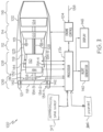
- some embodiments may include two particulate sensors 134 (134-2 and 134-6 in FIG. 3 ) at the second location (e.g., downstream of the fan 118) that are disposed 180-degrees apart.
- the processor 136 may determine the mass of particulate that passed each particulate sensor 134 at the same location and add the determined masses together to get the total mass at that location.
- the processor 136 is further configured to compare the mass of accumulated particulate to a threshold mass value.
- This threshold value may vary and may depend, for example, on the type of particulate being sensed, on the type of engine, and on the particular engine component.
- the threshold value for each type of particulate may be predetermined and stored in the memory 302 or it may be a user-supplied value that is input by a user.
- the processor 136 based on this comparison, determines that the accumulated mass exceeds the threshold mass value, the processor 136 generates a signal. This signal may be used to generate an alert, to initiate a mitigation or corrective action, or both.
- the threshold mass value for volcanic ash is 100 grams
- the processor 136 determines that 80 grams of volcanic ash has accumulated, then the threshold has not been exceeded.
- the processor determines that 120 grams of volcanic ash has accumulated, then the threshold has been exceeded, and generates an alert signal.
- the system 100 additionally includes the alert generator 140.
- the alert generator 140 may be implemented as a visual alert, an aural alert, a haptic alert, or any one of numerous combinations of these types of alerts. No matter how it is implemented, the alert generator 140 is coupled to receive the signal from the processor 136 and is configured, upon receipt of the signal, to generate an alert. The alert may communicate, for example, the type of particulate accumulated, which may in turn be used to determine a type of mitigation or corrective action to pursue.
- the signal When the signal is used to initiate a mitigation or corrective action, the signal may be supplied to one or more of the engine control 104, one or more anti-ice heaters 142, one or more controllable bypass channels (or valves) 144, and one or more display devices 146.
- the specific mitigation or corrective action may be a function of the particular type of accumulated particulate, and preferably results in preventing or mitigating further particulate accumulation.
- the engine control 104 is configured to, among other things, control at least the rotational speed of one or more of the gas turbine engine components. In some embodiments, the engine control 104 is further configured, upon receipt of the signal from the processor 136, to increase the rotational speed of one or more of the gas turbine components.
- the engine control 104 may also be configured, upon receipt of the signal, to vary the positions of the one or more variable geometry devices (e.g., the variable inlet guide vanes 132).
- the heaters 142 upon receipt of the signal, will generate heat.
- the signal from the processor 136 may also be used to open one or more of the controllable bypass channels 144.
- the signal may be supplied directly to the controllable bypass channels 144 or to the engine control 104, which in turn opens the channels. Regardless, opening the bypass channels 144 will provide a flow path from the compressor 110 to the bypass section 119, which will exhaust particulate along the compressor outer diameter flow path out to the bypass section 119, thereby bypassing the combustor 113 and turbines 122, 124.
- the display device 146 render, for example, a message to change the route or altitude of the vehicle (e.g., aircraft), to thereby exit the particulate source. It will be appreciated that the message may also, or instead, be supplied by the alert generator.
- the engine system 100 may include additional sensors. Indeed, in the depicted embodiment, the engine system 100 includes three additional particulate sensors 134 disposed at three different additional locations. More specifically, in addition to the first and second particulate sensors 134-1, 134-2, the depicted system 100 includes a third particulate sensor 134-3, a fourth particulate sensor 134-4, and a fifth particulate sensor 134-5.
- the third particulate sensor 134-3 is mounted at a third position on the gas turbine engine 102
- the fourth particulate sensor 134-4 is mounted at a fourth position on the gas turbine engine 102
- the fifth particulate sensor 134-5 is mounted at a fifth position on the gas turbine engine 102.
- the third position is located at a first side of a second gas turbine engine component and downstream of the second position
- the fourth position is located at a second side of the second gas turbine engine component and downstream of the third position.
- the second side of the second gas turbine engine component corresponds to the first side of a third gas turbine engine component
- the fifth position is located at the second side of the third gas turbine engine component and downstream of the fourth position.
- the second and third gas turbine engine components may vary, in the depicted embodiment each is a different stage (e.g., the first and second stages) of the compressor 110.
- the third particulate sensor 134-3 senses particulate at the third position and supplies a third sensor signal representative thereof to the processor 136
- the fourth particulate sensor 134-4 senses particulate at the fourth position and supplies a fourth sensor signal representative thereof to the processor 136
- the fifth particulate sensor senses particulate at the fifth position and supplies a fifth sensor signal representative thereof to the processor 136.
- the processor 136 upon receipt of the additional sensor signals, determines the type, quantity, and size of particulate at the different positions.
- the processor 136 additionally determines, based at least on the quantity and size of particulate at each of the different positions, the amount of particulate accumulated on one or more additional gas turbine engine components (e.g., the first and second compressor stages).
- FIG. 4 Another embodiment of a process for determining particulate accumulation in the gas turbine engine 102 that the system 100 implements is depicted, in flowchart form, in FIG. 4 , and will now be described.
- the depicted process 400 is when the system 100 includes only two particulate sensors 134 (e.g., the first and second particulate sensors), but could readily be expanded for a system that includes three or more sensors 134.
- the process 400 begins by sensing the number, size, and type of particulate at a first position on the gas turbine engine and supplying first data representative thereof (402), and sensing the number, size, and type of particulate at a second position on the gas turbine engine and supplying second data representative thereof (404).
- first position is located at a first side of a gas turbine engine component
- second position is located at a second side of the gas turbine engine component and downstream of the first position.
- the first data and the second data are processed to determine the mass of the particulate accumulated on the gas turbine engine component (406).
- the mass of particulate accumulated on the gas turbine engine component is then compared to a threshold mass value (408). If the mass exceeds the threshold mass value, then an alert is generated (412). If not, then the process 400 repeats. Though not depicted in FIG. 4 , it will be appreciated that the process 400 may be further expanded to include, for example, communicating the type of particulate accumulated on the gas turbine engine component, and/or initiating one or more mitigation or corrective actions.
- the systems and methods described herein differentiate between different types, quantities, and sizes of particulate at various locations within a gas turbine engine, which allows determining if, and how much, particulate is accumulating at various locations on or within the engine.
- a gas turbine engine particulate ingestion detection system includes a first particulate sensor, a second particulate sensor, and a processor.
- the first particulate sensor is mounted at a first position on the gas turbine engine, where the first position is located at a first side of a gas turbine engine component.
- the first particulate sensor is configured to sense particulate at the first position and supply a first sensor signal representative thereof.
- the second particulate sensor is mounted at a second position on the gas turbine engine, where the second position is located at a second side of the gas turbine engine component and downstream of the first position.
- the second particulate sensor is configured to sense particulate at the second position and supply a second sensor signal representative thereof.
- the processor is coupled to receive the first sensor signal and the second sensor signal.
- the processor is configured, upon receipt of the first and second sensors signal, to: (i) determine the type, quantity, and size of the particulate at the first position, (ii) determine the type, quantity, and size of the particulate at the second position, and (iii) determine, based at least on the quantity and size of the particulate at the first and second positions, an amount of particulate accumulated on the gas turbine engine component.
- the processor may be further configured to compare the amount of the particulate accumulated on the gas turbine engine component to a threshold value, and generate a signal when the amount exceeds the threshold value.
- the threshold value may depend on one or more of: the one or more types of particulate being sensed, the type of engine, and the particular engine component.
- An alert generator may be coupled to receive the signal from the processor and configured, upon receipt of the signal, to generate an alert.
- the alert may communicate the type of particulate accumulated on the gas turbine engine component.
- the signal may initiate one or more actions to prevent or mitigate further particulate accumulation.
- the one or more actions may include one or more of: increasing the rotational speed of one or more gas turbine engine components; varying positions of one or more variable geometry devices; energizing one or more heaters; opening one or more compressor bypass channels; and displaying one or more messages to exit a source of the particulate.
- the particulate may comprise one or more of water droplets, ice crystals, dust, and volcanic ash.
- the first and second sensors may each be selected from the group consisting of an optical sensor, a capacitive sensor, an electrostatic sensor, a lidar sensor, and a backscatter sensor.
- the system may further include a plurality of additional particulate sensors, where each additional particulate sensor is mounted at different positions on the gas turbine engine that are each different from the first and second positions, and each additional particulate sensor is configured to sense particulate at its position and supply an additional sensor signal representative thereof, and the processor may be further coupled to receive each of the additional sensor signals, and further configured, upon receipt of the additional sensors signal, to: determine type, quantity, and size of particulate at the different positions, and determine, based at least on the quantity and size of particulate at each of the different positions, an amount of the particulate accumulated on one or more additional gas turbine engine components.
- T he first turbine engine component may be a fan, and the additional turbine engine components may include a first compressor stage and a second compressor stage.
- a method for determining particulate accumulation in a gas turbine engine includes sensing particulate at a first position on the gas turbine engine and supplying a first sensor signal representative thereof, where the first position is located at a first side of a gas turbine engine component, and sensing particulate at a second position on the gas turbine engine and supplying a second sensor signal representative thereof, where the second position is located at a second side of the gas turbine engine component and downstream of the first position.
- the first sensor signal is processed to determine the type, quantity, and size of the particulate at the first position
- the second sensor signal is processed to determine the type, quantity, and size of the particulate at the second position. Based at least on the quantity and size of the particulate at the first and the second positions, an amount of the particulate accumulated on the gas turbine engine component is determined.
- aspects and other embodiments may include one or more of the following features. Comparing the amount of the particulate accumulated on the gas turbine engine component to a threshold value, and generating an alert when the amount exceeds the threshold value.
- the threshold value may depend on one or more of: the one or more types of particulate being sensed, the type of engine, and the particular engine component.
- the alert may communicate the type of particulate accumulated on the gas turbine engine component.
- One or more actions to prevent or mitigate further particulate accumulation may be initiated.
- the one or more actions may include one or more of: increasing the rotational speed of one or more gas turbine engine components; varying positions of one or more variable geometry devices; energizing one or more heaters; opening one or more compressor bypass channels; and displaying one or more messages to exit a source of the particulate.
- the particulate may comprise one or more of water droplets, ice crystals, dust, and volcanic ash. Sensing particulate at a plurality of positions in the gas turbine engine that are each different from the first and second positions, and supplying a plurality of additional sensor signals.
- a gas turbine engine particulate ingestion detection system wherein the particulate is one or both of super cooled liquid droplets and frozen ice particles, includes a first particulate sensor, a second particulate sensor, and a processor.
- the first particulate sensor is mounted at a first position on the gas turbine engine, where the first position located at a first side of a gas turbine engine component.
- the first particulate sensor is configured to sense particulate at the first position and supply a first sensor signal representative thereof.
- the second particulate sensor is mounted at a second position on the gas turbine engine, where the second position located at a second side of the gas turbine engine component and downstream of the first position.
- the second particulate sensor is configured to sense particulate at the second position and supply a second sensor signal representative thereof.
- the processor is coupled to receive the first sensor signal and the second sensor signal, and is configured, upon receipt of the first and second sensors signal, to: (i) determine the type, quantity, and size of the particulate at the first position, (ii) determine the type, quantity, and size of the particulate at the second position, (iii) determine, based at least on the quantity and size of the particulate at the first and second positions, an amount of ice accreted on the gas turbine engine component, (iv) compare the amount of ice accreted on the gas turbine engine component to a threshold value, and (v) generate a signal when the amount exceeds the threshold value.
- a gas turbine engine particulate ingestion detection system includes a first particulate sensor, a second particulate sensor, and a processor.
- the first particulate sensor is mounted at a first position on the gas turbine engine, where the first position is located at a first side of a gas turbine engine component.
- the first particulate sensor is configured to sense the number, size, and type of particulate at the first position and supply first data representative thereof.
- the second particulate sensor is mounted at a second position on the gas turbine engine, where the second position is located at a second side of the gas turbine engine component and downstream of the first position.
- the second particulate sensor is configured to sense the number, size, and type of particulate at the second position and supply second data representative thereof.
- the processor is coupled to receive the first and second data from the first and second particulate sensors, respectively.
- the processor is configured, upon receipt of the first and second data, to determine, based at least on the number, size, and type of the particulate at the first and second positions, the mass of the particulate accumulated on the gas turbine engine component.
- the processor may be further configured to compare the mass of the particulate accumulated on the gas turbine engine component to a threshold mass value, and generate a signal when the mass exceeds the threshold mass value.
- the threshold mass value may depend on one or more of: the one or more types of particulate being sensed, the type of engine, and the particular engine component.
- An alert generator may be coupled to receive the signal from the processor and configured, upon receipt of the signal, to generate an alert. The alert may communicate the type of particulate accumulated on the gas turbine engine component. The signal may initiate one or more actions to prevent or mitigate further particulate accumulation.
- the one or more actions may include one or more of: increasing the rotational speed of one or more gas turbine engine components; varying positions of one or more variable geometry devices; energizing one or more heaters; opening one or more compressor bypass channels; and displaying one or more messages to exit a source of the particulate.
- the particulate may comprise one or more of water droplets, ice crystals, dust, and volcanic ash.
- the system may further include a plurality of additional particulate sensors, where each additional particulate sensor mounted at a corresponding position on the gas turbine engine that is different from the first and second positions. Each additional particulate sensor is configured to sense the number, size, and type of particulate at its corresponding position and supply additional data representative thereof.
- the processor is further coupled to receive the additional data from each of the additional sensor signals, and is further configured, upon receipt of the additional data determine, based at least on the number, size, and type of the particulate at the corresponding positions, a mass of the particulate accumulated on one or more additional gas turbine engine components.
- the first turbine engine component may be a fan, and the additional turbine engine components may include a first compressor stage and a second compressor stage.
- a method for determining particulate accumulation in a gas turbine engine includes sensing the number, size, and type of particulate at a first position on the gas turbine engine and supplying first data representative thereof, where the first position located at a first side of a gas turbine engine component; sensing the number, size, and type of particulate at a second position on the gas turbine engine and supplying first data representative thereof, where the second position located at a second side of the gas turbine engine component and downstream of the first position; and processing the first data and the second data to determine the mass of the particulate accumulated on the gas turbine engine component.
- aspects and other embodiments may include one or more of the following features. Comparing the mass of the particulate accumulated on the gas turbine engine component to a threshold mass value, and generating an alert when the mass exceeds the threshold mass value.
- the threshold mass value may depend on one or more of: the one or more types of particulate being sensed, the type of engine, and the particular engine component.
- the alert may communicate the type of particulate accumulated on the gas turbine engine component.
- One or more actions to prevent or mitigate further particulate accumulation may be initiated.
- the one or more actions may include one or more of: increasing the rotational speed of one or more gas turbine engine components; varying positions of one or more variable geometry devices; energizing one or more heaters; opening one or more compressor bypass channels; and displaying one or more messages to exit a source of the particulate.
- the particulate may comprise one or more of water droplets, ice crystals, dust, and volcanic ash. Sensing the number, size, and type of particulate at a plurality of positions in the gas turbine engine that are each different from the first and second positions, and supplying a plurality of additional data representative thereof. Processing each of the additional data to determine the mass of the particulate accumulated on one or more additional gas turbine engine components.
- Skilled artisans may implement the described functionality in varying ways for each particular application, but such implementation decisions should not be interpreted as causing a departure from the scope of the present invention.
- an embodiment of a system or a component may employ various integrated circuit components, e.g., memory elements, digital signal processing elements, logic elements, look-up tables, or the like, which may carry out a variety of functions under the control of one or more microprocessors or other control devices.
- integrated circuit components e.g., memory elements, digital signal processing elements, logic elements, look-up tables, or the like, which may carry out a variety of functions under the control of one or more microprocessors or other control devices.
- DSP digital signal processor
- ASIC application specific integrated circuit
- FPGA field programmable gate array
- a general-purpose processor may be a microprocessor, but in the alternative, the processor may be any conventional processor, controller, microcontroller, or state machine.
- a processor may also be implemented as a combination of computing devices, e.g., a combination of a DSP and a microprocessor, a plurality of microprocessors, one or more microprocessors in conjunction with a DSP core, or any other such configuration.
- a software module may reside in RAM memory, flash memory, ROM memory, EPROM memory, EEPROM memory, registers, hard disk, a removable disk, a CD-ROM, or any other form of storage medium known in the art.
- An exemplary storage medium is coupled to the processor such that the processor can read information from, and write information to, the storage medium.
- the storage medium may be integral to the processor.
- the processor and the storage medium may reside in an ASIC.
- an embodiment of a system or a component may employ various integrated circuit components, e.g., memory elements, digital signal processing elements, logic elements, look-up tables, or the like, which may carry out a variety of functions under the control of one or more microprocessors or other control devices.
- integrated circuit components e.g., memory elements, digital signal processing elements, logic elements, look-up tables, or the like, which may carry out a variety of functions under the control of one or more microprocessors or other control devices.
- various elements of the systems described herein are essentially the code segments or instructions that perform the various tasks.
- the program or code segments can be stored in a processor-readable medium or transmitted by a computer data signal embodied in a carrier wave over a transmission medium or communication path.
- the "computer-readable medium”, “processor-readable medium”, or “machine-readable medium” may include any medium that can store or transfer information. Examples of the processor-readable medium include an electronic circuit, a semiconductor memory device, a ROM, a flash memory, an erasable ROM (EROM), a floppy diskette, a CD-ROM, an optical disk, a hard disk, a fiber optic medium, a radio frequency (RF) link, or the like.
- RF radio frequency
- the computer data signal may include any signal that can propagate over a transmission medium such as electronic network channels, optical fibers, air, electromagnetic paths, or RF links.
- the code segments may be downloaded via computer networks such as the Internet, an intranet, a LAN, or the like.
Landscapes
- Engineering & Computer Science (AREA)
- Chemical & Material Sciences (AREA)
- Mechanical Engineering (AREA)
- Physics & Mathematics (AREA)
- General Physics & Mathematics (AREA)
- General Engineering & Computer Science (AREA)
- Dispersion Chemistry (AREA)
- Aviation & Aerospace Engineering (AREA)
- Combustion & Propulsion (AREA)
- Health & Medical Sciences (AREA)
- Life Sciences & Earth Sciences (AREA)
- Analytical Chemistry (AREA)
- Biochemistry (AREA)
- General Health & Medical Sciences (AREA)
- Immunology (AREA)
- Pathology (AREA)
- Control Of Turbines (AREA)
- Other Investigation Or Analysis Of Materials By Electrical Means (AREA)
Claims (15)
- Gasturbinentriebwerk-Partikelaufnahme-Detektionssystem (100), umfassend:einen ersten Partikelsensor (134-1), der an einer ersten Position am Gasturbinentriebwerk angebracht ist, wobei sich die erste Position an einer ersten Seite einer Gasturbinentriebwerkskomponente befindet, wobei der erste Partikelsensor so konfiguriert ist, dass er die Anzahl, die Größe und die Art der Partikel an der ersten Position wahrnimmt und erste dafür charakteristische Daten liefert;einen zweiten Partikelsensor (134-2), der an einer zweiten Position an der Gasturbinenmaschine angebracht ist, wobei sich die zweite Position an einer zweiten Seite der Gasturbinentriebwerkskomponente und nachgelagert zu der ersten Position befindet, wobei der zweite Partikelsensor so konfiguriert ist, dass er die Anzahl, die Größe und die Art der Partikel an der zweiten Position wahrnimmt und zweite dafür charakteristische Daten liefert; undeinen Prozessor (136), der so gekoppelt ist, dass er die ersten und zweiten Daten vom ersten bzw. zweiten Partikelsensor empfängt, wobei der Prozessor so konfiguriert ist, dass er nach Empfang der ersten und zweiten Daten zumindest aufgrund der Anzahl, der Größe und der Art der Partikel an der ersten und zweiten Position eine Masse der an der Gasturbinentriebwerkskomponente angesammelten Partikel bestimmt;eine Quelle für Flugzeugumweltdaten (304), die so konfiguriert ist, dass sie für Umweltparameter charakteristische Daten bereitstellt;einen Speicher (302), der Dichten von Partikelarten speichert, wobei die Dichten aufgrund von Umgebungsparametern variieren, die einen oder mehrere von Umgebungstemperatur, Umgebungsdruck und Flughöhe einschließen;wobei der Prozessor (136) so konfiguriert ist, dass er die Masse der auf der Gasturbinentriebwerkskomponente angesammelten Partikel bestimmt, indem er die Anzahl von mindestens einer Partikelart, die den ersten Partikelsensor (134-1) während einer vorbestimmten Abtastzeitperiode passiert hat, mit der Größe der mindestens einen Partikelart und mit einer Dichte, die der mindestens einen Partikelart zugeordnet ist, multipliziert, um einen ersten Wert zu erhalten, und dann die Anzahl der mindestens einen Partikelart, die den zweiten Partikelsensor (134-2) während einer vorbestimmten Zeitdauer der Probenahme passiert hat, mit der Größe der mindestens einen Partikelart und mit einer Dichte, die der mindestens einen Partikelart zugeordnet ist, multipliziert, um einen zweiten Wert zu erhalten; unddas Subtrahieren des zweiten Wertes von dem ersten Wert, um eine Masse der mindestens einen Partikelart zu erhalten, die sich während der vorbestimmten Abtastzeitperiode auf der Gasturbinentriebwerkskomponente angesammelt hat.
- System nach Anspruch 1, wobei der Prozessor ferner dazu konfiguriert ist:die Masse der auf der Gasturbinentriebwerkskomponente angesammelten Partikel mit einem Massenschwellenwert zu vergleichen; undein Signal zu erzeugen, wenn die Masse den Massenschwellenwert überschreitet.
- System nach Anspruch 2, wobei der Massenschwellenwert von einem oder mehreren abhängt von: der einen oder mehreren Partikelarten, die wahrgenommen werden, der Triebwerksart und der betreffenden Triebwerkskomponente.
- System nach Anspruch 2 oder 3, ferner umfassend:
einen Alarmgenerator (140), der so gekoppelt ist, dass er das Signal von dem Prozessor empfängt, und der so konfiguriert ist, dass er bei Empfang des Signals einen Alarm erzeugt. - System nach Anspruch 4, wobei der Alarm die Partikelart mitteilt, die sich auf der Gasturbinentriebwerkskomponente angesammelt hat.
- System nach Anspruch 2, 3, 4 oder 5, wobei das Signal eine oder mehrere Aktionen auslöst, um eine weitere Partikelansammlung zu verhindern oder zu mindern, wobei gegebenenfalls die eine oder mehreren Aktionen eines oder mehrere einschließen von:Erhöhen der Drehzahl von einer oder mehreren Gasturbinentriebwerkskomponenten;Verändern der Positionen von einer oder mehreren Vorrichtungen mit variabler Geometrie;Einschalten von einer oder mehreren Heizungen;Öffnen von einem oder mehreren Verdichter-Bypass-Kanälen; undAnzeigen von einer oder mehreren Meldungen zum Verlassen einer Partikelquelle.
- System nach einem der vorherigen Ansprüche, wobei die Partikel eines oder mehrere umfassen von Wassertröpfchen, Eiskristallen, Staub und Vulkanasche.
- System nach einem der vorherigen Ansprüche, ferner umfassend:
einen dritten Partikelsensor (134-3), der an der zweiten Position am Gasturbinentriebwerk angebracht ist, wobei der dritte Partikelsensor so konfiguriert ist, dass er die Anzahl, die Größe und die Partikelart an der zweiten Position wahrnimmt und dritte Daten, die dafür charakteristisch sind, an den Prozessor liefert. - System nach einem der vorherigen Ansprüche, ferner umfassend:
eine Vielzahl von zusätzlichen Partikelsensoren, wobei jeder zusätzliche Partikelsensor an einer entsprechenden Position am Gasturbinentriebwerk angebracht ist, die sich von der ersten und der zweiten Position unterscheidet, wobei jeder zusätzliche Partikelsensor so konfiguriert ist, dass er die Anzahl, die Größe und die Partikelart an seiner entsprechenden Position wahrnimmt und zusätzliche Daten liefert, die dafür charakteristisch sind, wobei der Prozessor ferner so gekoppelt ist, dass er die zusätzlichen Daten von jedem der zusätzlichen Sensorsignale empfängt, und ferner so konfiguriert ist, dass er nach Empfang der zusätzlichen Daten:mindestens basierend auf der Anzahl, der Größe und der Partikelart der Partikel an den entsprechenden Positionen eine Masse der Partikel bestimmt, die sich an einer oder mehreren zusätzlichen Gasturbinentriebwerkskomponenten angesammelt hat, wobei gegebenenfalls die erste Gasturbinentriebwerkskomponente ein Lüfter ist; unddie zusätzlichen Turbinentriebwerkskomponenten eine erste Verdichterstufe und eine zweite Verdichterstufe einschließen. - Verfahren zur Bestimmung der Partikelansammlung in einem Gasturbinentriebwerk (102), wobei das Verfahren die Schritte umfasst:Wahrnehmen der Anzahl, Größe und Partikelart an einer ersten Position am Gasturbinentriebwerk mit einem ersten Partikelsensor (134-1) und Liefern erster dafür charakteristischer Daten, wobei sich die erste Position an einer ersten Seite einer Gasturbinentriebwerkskomponente befindet;Wahrnehmen der Anzahl, Größe und Partikelart an einer zweiten Position am Gasturbinentriebwerk mit einem zweiten Partikelsensor (134-2) und Liefern zweiter dafür charakteristischer Daten, wobei sich die zweite Position an einer zweiten Seite der Gasturbinentriebwerkskomponente und der ersten Position nachgelagert befindet;Verarbeiten der ersten Daten und der zweiten Daten, um eine Masse der Partikelart zu bestimmen, die sich an der Gasturbinentriebwerkskomponente angesammelt hat, wobei eine Dichte der Partikelart in einem Speicher (302) gespeichert ist und aufgrund eines Umgebungsparameters variiert, der eines oder mehrere von Umgebungstemperatur, Umgebungsdruck und Flughöhe einschließt, und wobei eine Quelle für Flugzeugumgebungsdaten (304) Daten bereitstellt, die charakteristisch für den einen oder die mehreren dieser Umgebungsparameter sind, und wobei die Masse der Partikel, die sich an der Gasturbinentriebwerkskomponente angesammelt hat, bestimmt wird, indem die Anzahl von mindestens einer Partikelart, die den ersten Partikelsensor (134-1) während einer vorbestimmten Abtastzeitperiode passiert hat, mit der Größe der mindestens einen Partikelart und mit einer mit der mindestens einen Partikelart verbundenen Dichte multipliziert wird, um einen ersten Wert zu erhalten, und dann die Anzahl der mindestens einen Partikelart, die den zweiten Partikelsensor (134-2) während einer vorbestimmten Abtastzeitperiode passiert hat, mit der Größe der mindestens einen Partikelart und mit einer der mindestens einen Partikelart zugeordneten Dichte multipliziert wird, um einen zweiten Wert zu erhalten;Subtrahieren des zweiten Wertes von dem ersten Wert, um eine Masse der mindestens einen Partikelart zu erhalten, die sich während der vorbestimmten Abtastzeitperiode auf der Gasturbinentriebwerkskomponente angesammelt hat.
- Verfahren nach Anspruch 10, ferner umfassend:Vergleichen der Masse der auf der Gasturbinentriebwerkskomponente angesammelten Partikel mit einem Massenschwellenwert; undErzeugen eines Signals, wenn die Masse den Massenschwellenwert überschreitet.
- Verfahren nach Anspruch 11, wobei der Massenschwellenwert von einem oder mehreren abhängt von:
der einen oder den mehreren Partikelarten, die wahrgenommen werden, dem Triebwerkstyp und der betreffenden Triebwerkskomponente, und/oder wobei der Alarm die Partikelart mitteilt, die sich an der Gasturbinentriebwerkskomponente angesammelt hat. - Verfahren nach Anspruch 11 oder 12, ferner umfassend das Einleiten einer oder mehrerer Aktionen, um eine weitere Partikelansammlung zu verhindern oder zu mindern, wobei gegebenenfalls die eine oder mehreren Aktionen eines oder mehrere einschließen von:Erhöhen der Drehzahl von einer oder mehreren Gasturbinentriebwerkskomponenten;Verändern der Positionen von einer oder mehreren Vorrichtungen mit variabler Geometrie;Einschalten von einer oder mehreren Heizungen;Öffnen von einem oder mehreren Verdichter-Bypass-Kanälen; undAnzeigen von einer oder mehreren Meldungen zum Verlassen einer Partikelquelle.
- Verfahren nach Anspruch 11, 12 oder 13, wobei die Partikel eines oder mehrere von Wassertröpfchen, Eiskristallen, Staub und Vulkanasche umfassen.
- Verfahren nach Anspruch 11, 12, 13 oder 14, ferner umfassend:Wahrnehmen der Anzahl, Größe und Partikelart an einer Vielzahl von Positionen in der Gasturbinenmaschine mit einer Vielzahl von zusätzlichen Partikelsensoren, die sich jeweils von der ersten und der zweiten Position unterscheiden, und Liefern einer Vielzahl von zusätzlichen Daten, die dafür charakteristisch sind;Verarbeiten jeder der zusätzlichen Daten, um eine Masse der Partikel zu bestimmen, die sich an einer oder mehreren zusätzlichen Gasturbinentriebwerkskomponenten angesammelt hat, und / oder ferner umfassend:
Wahrnehmen der Anzahl, Größe und Partikelart der Partikel an der zweiten Position am Gasturbinentriebwerk mit einem dritten Partikelsensor (134-3) und Liefern dritter dafür charakteristischer Daten an den Prozessor.
Priority Applications (1)
| Application Number | Priority Date | Filing Date | Title |
|---|---|---|---|
| EP20166876.1A EP3889395B1 (de) | 2020-03-30 | 2020-03-30 | Gasturbinenmotor mit partikelaufnahme- und akkumulationssensorsystem und -verfahren |
Applications Claiming Priority (1)
| Application Number | Priority Date | Filing Date | Title |
|---|---|---|---|
| EP20166876.1A EP3889395B1 (de) | 2020-03-30 | 2020-03-30 | Gasturbinenmotor mit partikelaufnahme- und akkumulationssensorsystem und -verfahren |
Publications (2)
| Publication Number | Publication Date |
|---|---|
| EP3889395A1 EP3889395A1 (de) | 2021-10-06 |
| EP3889395B1 true EP3889395B1 (de) | 2024-02-28 |
Family
ID=70108074
Family Applications (1)
| Application Number | Title | Priority Date | Filing Date |
|---|---|---|---|
| EP20166876.1A Active EP3889395B1 (de) | 2020-03-30 | 2020-03-30 | Gasturbinenmotor mit partikelaufnahme- und akkumulationssensorsystem und -verfahren |
Country Status (1)
| Country | Link |
|---|---|
| EP (1) | EP3889395B1 (de) |
Families Citing this family (3)
| Publication number | Priority date | Publication date | Assignee | Title |
|---|---|---|---|---|
| EP4292941A1 (de) * | 2022-06-15 | 2023-12-20 | Zero Emissions Aerospace Limited | Anti-kontaminationssystem für flugzeugbrennstoffzellen |
| US12331681B2 (en) | 2023-05-09 | 2025-06-17 | Rtx Corporation | Aircraft precipitation monitoring system |
| US12391393B2 (en) | 2023-07-20 | 2025-08-19 | Rtx Corporation | Aircraft propulsion system with inlet air monitoring system and method |
Family Cites Families (5)
| Publication number | Priority date | Publication date | Assignee | Title |
|---|---|---|---|---|
| GB0917319D0 (en) * | 2009-10-05 | 2009-11-18 | Rolls Royce Plc | An apparatus and method of operating a gas turbine engine |
| US8459103B2 (en) * | 2011-06-24 | 2013-06-11 | United Technologies Corporation | IDMS signal processing to distinguish inlet particulates |
| US9222873B2 (en) | 2013-05-02 | 2015-12-29 | Droplet Measurement Technologies, Inc. | Optical particle detector |
| US9776731B1 (en) * | 2016-09-29 | 2017-10-03 | The Boeing Company | Methods and apparatus for detecting aircraft surface deformations |
| US20180298778A1 (en) * | 2017-04-18 | 2018-10-18 | Honeywell International Inc. | Gas turbine engine particulate ingestion and accumulation sensor system and method |
-
2020
- 2020-03-30 EP EP20166876.1A patent/EP3889395B1/de active Active
Also Published As
| Publication number | Publication date |
|---|---|
| EP3889395A1 (de) | 2021-10-06 |
Similar Documents
| Publication | Publication Date | Title |
|---|---|---|
| US11149583B2 (en) | Gas turbine engine particulate ingestion and accumulation sensor system and method | |
| EP3392467B1 (de) | Partikeldetektionssystem für ein gasturbinentriebwerk und zugehöriges verfahren | |
| EP3889395A1 (de) | Gasturbinenmotor mit partikelaufnahme- und akkumulationssensorsystem und -verfahren | |
| EP3039270B1 (de) | Nachweis von flammendurchschlag bei einer gasturbine | |
| Garg | Controls and health management technologies for intelligent aerospace propulsion systems | |
| US20180164796A1 (en) | Gas turbine engine fleet performance deterioration | |
| JP2001107749A (ja) | 航空機用ガスタービン・エンジンの制御装置 | |
| US8869603B2 (en) | Debris detection in turbomachinery and gas turbine engines | |
| EP3139143A1 (de) | System und verfahren zur bestimmung der gesamtlufttemperatur aus einer turbofan-mantelstromtemperatur | |
| EP3712737B1 (de) | Signalantwortüberwachung für turbinenmotoren | |
| EP3409926B1 (de) | Verfahren und system zur detektion eines hochtemperaturzustands einer gasturbine | |
| CN116620555B (zh) | 用于提供关于飞行器发动机内的颗粒物的信息的系统和方法 | |
| US10082243B1 (en) | Method and system for inlet blockage detection | |
| Prahst et al. | Experimental results of the first two stages of an advanced transonic core compressor under isolated and multi-stage conditions | |
| CN114202823A (zh) | 预报用于预测分析的飞行器发动机操作数据的系统和方法 | |
| Scala et al. | Predicting the performance of a gas turbine engine undergoing compressor blade erosion | |
| Jorgenson et al. | Modeling the deterioration of engine and low pressure compressor performance during a rollback event due to ice accretion | |
| May et al. | Engine icing modeling and simulation (Part 2): Performance simulation of engine rollback phenomena | |
| CN116577001A (zh) | 颗粒传感器在发动机功率保证中的使用 | |
| RU2310100C2 (ru) | Способ защиты газотурбинного двигателя от возникновения неустойчивой работы компрессора | |
| US12391393B2 (en) | Aircraft propulsion system with inlet air monitoring system and method | |
| Jorgenson et al. | Modeling of Commercial Turbofan Engine With Ice Crystal Ingestion: Follow-On | |
| May et al. | Detection of the Impact of Ice Crystal Accretion in an Aircraft Engine Compression System During Dynamic Operation | |
| Davis Jr et al. | 40 Years of AEDC Development, Evolution and Application of Numerical Simulations for Integrated Test and Evaluation of Turbine Engine Turbomachinery Operability Issues | |
| May et al. | Modeling and Detection of Ice Particle Accretion in Aircraft Engine Compression Systems |
Legal Events
| Date | Code | Title | Description |
|---|---|---|---|
| PUAI | Public reference made under article 153(3) epc to a published international application that has entered the european phase |
Free format text: ORIGINAL CODE: 0009012 |
|
| STAA | Information on the status of an ep patent application or granted ep patent |
Free format text: STATUS: THE APPLICATION HAS BEEN PUBLISHED |
|
| AK | Designated contracting states |
Kind code of ref document: A1 Designated state(s): AL AT BE BG CH CY CZ DE DK EE ES FI FR GB GR HR HU IE IS IT LI LT LU LV MC MK MT NL NO PL PT RO RS SE SI SK SM TR |
|
| STAA | Information on the status of an ep patent application or granted ep patent |
Free format text: STATUS: REQUEST FOR EXAMINATION WAS MADE |
|
| 17P | Request for examination filed |
Effective date: 20220329 |
|
| RBV | Designated contracting states (corrected) |
Designated state(s): AL AT BE BG CH CY CZ DE DK EE ES FI FR GB GR HR HU IE IS IT LI LT LU LV MC MK MT NL NO PL PT RO RS SE SI SK SM TR |
|
| RAP3 | Party data changed (applicant data changed or rights of an application transferred) |
Owner name: HONEYWELL INTERNATIONAL INC. |
|
| STAA | Information on the status of an ep patent application or granted ep patent |
Free format text: STATUS: EXAMINATION IS IN PROGRESS |
|
| 17Q | First examination report despatched |
Effective date: 20221130 |
|
| P01 | Opt-out of the competence of the unified patent court (upc) registered |
Effective date: 20230421 |
|
| GRAP | Despatch of communication of intention to grant a patent |
Free format text: ORIGINAL CODE: EPIDOSNIGR1 |
|
| STAA | Information on the status of an ep patent application or granted ep patent |
Free format text: STATUS: GRANT OF PATENT IS INTENDED |
|
| RIC1 | Information provided on ipc code assigned before grant |
Ipc: G01N 15/00 20060101ALI20230825BHEP Ipc: B64D 45/00 20060101ALI20230825BHEP Ipc: G01N 15/06 20060101ALI20230825BHEP Ipc: G01M 15/14 20060101ALI20230825BHEP Ipc: F01D 21/00 20060101ALI20230825BHEP Ipc: F01D 17/02 20060101AFI20230825BHEP |
|
| INTG | Intention to grant announced |
Effective date: 20231002 |
|
| GRAS | Grant fee paid |
Free format text: ORIGINAL CODE: EPIDOSNIGR3 |
|
| GRAA | (expected) grant |
Free format text: ORIGINAL CODE: 0009210 |
|
| STAA | Information on the status of an ep patent application or granted ep patent |
Free format text: STATUS: THE PATENT HAS BEEN GRANTED |
|
| AK | Designated contracting states |
Kind code of ref document: B1 Designated state(s): AL AT BE BG CH CY CZ DE DK EE ES FI FR GB GR HR HU IE IS IT LI LT LU LV MC MK MT NL NO PL PT RO RS SE SI SK SM TR |
|
| REG | Reference to a national code |
Ref country code: GB Ref legal event code: FG4D |
|
| REG | Reference to a national code |
Ref country code: CH Ref legal event code: EP |
|
| REG | Reference to a national code |
Ref country code: DE Ref legal event code: R096 Ref document number: 602020026281 Country of ref document: DE |
|
| REG | Reference to a national code |
Ref country code: IE Ref legal event code: FG4D |
|
| REG | Reference to a national code |
Ref country code: LT Ref legal event code: MG9D |
|
| PG25 | Lapsed in a contracting state [announced via postgrant information from national office to epo] |
Ref country code: IS Free format text: LAPSE BECAUSE OF FAILURE TO SUBMIT A TRANSLATION OF THE DESCRIPTION OR TO PAY THE FEE WITHIN THE PRESCRIBED TIME-LIMIT Effective date: 20240628 |
|
| REG | Reference to a national code |
Ref country code: NL Ref legal event code: MP Effective date: 20240228 |
|
| PG25 | Lapsed in a contracting state [announced via postgrant information from national office to epo] |
Ref country code: LT Free format text: LAPSE BECAUSE OF FAILURE TO SUBMIT A TRANSLATION OF THE DESCRIPTION OR TO PAY THE FEE WITHIN THE PRESCRIBED TIME-LIMIT Effective date: 20240228 |
|
| PG25 | Lapsed in a contracting state [announced via postgrant information from national office to epo] |
Ref country code: GR Free format text: LAPSE BECAUSE OF FAILURE TO SUBMIT A TRANSLATION OF THE DESCRIPTION OR TO PAY THE FEE WITHIN THE PRESCRIBED TIME-LIMIT Effective date: 20240529 |
|
| PG25 | Lapsed in a contracting state [announced via postgrant information from national office to epo] |
Ref country code: HR Free format text: LAPSE BECAUSE OF FAILURE TO SUBMIT A TRANSLATION OF THE DESCRIPTION OR TO PAY THE FEE WITHIN THE PRESCRIBED TIME-LIMIT Effective date: 20240228 Ref country code: RS Free format text: LAPSE BECAUSE OF FAILURE TO SUBMIT A TRANSLATION OF THE DESCRIPTION OR TO PAY THE FEE WITHIN THE PRESCRIBED TIME-LIMIT Effective date: 20240528 Ref country code: NL Free format text: LAPSE BECAUSE OF FAILURE TO SUBMIT A TRANSLATION OF THE DESCRIPTION OR TO PAY THE FEE WITHIN THE PRESCRIBED TIME-LIMIT Effective date: 20240228 |
|
| PG25 | Lapsed in a contracting state [announced via postgrant information from national office to epo] |
Ref country code: ES Free format text: LAPSE BECAUSE OF FAILURE TO SUBMIT A TRANSLATION OF THE DESCRIPTION OR TO PAY THE FEE WITHIN THE PRESCRIBED TIME-LIMIT Effective date: 20240228 |
|
| PG25 | Lapsed in a contracting state [announced via postgrant information from national office to epo] |
Ref country code: RS Free format text: LAPSE BECAUSE OF FAILURE TO SUBMIT A TRANSLATION OF THE DESCRIPTION OR TO PAY THE FEE WITHIN THE PRESCRIBED TIME-LIMIT Effective date: 20240528 Ref country code: NO Free format text: LAPSE BECAUSE OF FAILURE TO SUBMIT A TRANSLATION OF THE DESCRIPTION OR TO PAY THE FEE WITHIN THE PRESCRIBED TIME-LIMIT Effective date: 20240528 Ref country code: NL Free format text: LAPSE BECAUSE OF FAILURE TO SUBMIT A TRANSLATION OF THE DESCRIPTION OR TO PAY THE FEE WITHIN THE PRESCRIBED TIME-LIMIT Effective date: 20240228 Ref country code: LT Free format text: LAPSE BECAUSE OF FAILURE TO SUBMIT A TRANSLATION OF THE DESCRIPTION OR TO PAY THE FEE WITHIN THE PRESCRIBED TIME-LIMIT Effective date: 20240228 Ref country code: IS Free format text: LAPSE BECAUSE OF FAILURE TO SUBMIT A TRANSLATION OF THE DESCRIPTION OR TO PAY THE FEE WITHIN THE PRESCRIBED TIME-LIMIT Effective date: 20240628 Ref country code: HR Free format text: LAPSE BECAUSE OF FAILURE TO SUBMIT A TRANSLATION OF THE DESCRIPTION OR TO PAY THE FEE WITHIN THE PRESCRIBED TIME-LIMIT Effective date: 20240228 Ref country code: GR Free format text: LAPSE BECAUSE OF FAILURE TO SUBMIT A TRANSLATION OF THE DESCRIPTION OR TO PAY THE FEE WITHIN THE PRESCRIBED TIME-LIMIT Effective date: 20240529 Ref country code: FI Free format text: LAPSE BECAUSE OF FAILURE TO SUBMIT A TRANSLATION OF THE DESCRIPTION OR TO PAY THE FEE WITHIN THE PRESCRIBED TIME-LIMIT Effective date: 20240228 Ref country code: ES Free format text: LAPSE BECAUSE OF FAILURE TO SUBMIT A TRANSLATION OF THE DESCRIPTION OR TO PAY THE FEE WITHIN THE PRESCRIBED TIME-LIMIT Effective date: 20240228 Ref country code: BG Free format text: LAPSE BECAUSE OF FAILURE TO SUBMIT A TRANSLATION OF THE DESCRIPTION OR TO PAY THE FEE WITHIN THE PRESCRIBED TIME-LIMIT Effective date: 20240228 |
|
| PG25 | Lapsed in a contracting state [announced via postgrant information from national office to epo] |
Ref country code: PT Free format text: LAPSE BECAUSE OF FAILURE TO SUBMIT A TRANSLATION OF THE DESCRIPTION OR TO PAY THE FEE WITHIN THE PRESCRIBED TIME-LIMIT Effective date: 20240628 Ref country code: PL Free format text: LAPSE BECAUSE OF FAILURE TO SUBMIT A TRANSLATION OF THE DESCRIPTION OR TO PAY THE FEE WITHIN THE PRESCRIBED TIME-LIMIT Effective date: 20240228 |
|
| REG | Reference to a national code |
Ref country code: AT Ref legal event code: MK05 Ref document number: 1661423 Country of ref document: AT Kind code of ref document: T Effective date: 20240228 |
|
| PG25 | Lapsed in a contracting state [announced via postgrant information from national office to epo] |
Ref country code: SE Free format text: LAPSE BECAUSE OF FAILURE TO SUBMIT A TRANSLATION OF THE DESCRIPTION OR TO PAY THE FEE WITHIN THE PRESCRIBED TIME-LIMIT Effective date: 20240228 Ref country code: PT Free format text: LAPSE BECAUSE OF FAILURE TO SUBMIT A TRANSLATION OF THE DESCRIPTION OR TO PAY THE FEE WITHIN THE PRESCRIBED TIME-LIMIT Effective date: 20240628 Ref country code: PL Free format text: LAPSE BECAUSE OF FAILURE TO SUBMIT A TRANSLATION OF THE DESCRIPTION OR TO PAY THE FEE WITHIN THE PRESCRIBED TIME-LIMIT Effective date: 20240228 Ref country code: LV Free format text: LAPSE BECAUSE OF FAILURE TO SUBMIT A TRANSLATION OF THE DESCRIPTION OR TO PAY THE FEE WITHIN THE PRESCRIBED TIME-LIMIT Effective date: 20240228 |
|
| PG25 | Lapsed in a contracting state [announced via postgrant information from national office to epo] |
Ref country code: DK Free format text: LAPSE BECAUSE OF FAILURE TO SUBMIT A TRANSLATION OF THE DESCRIPTION OR TO PAY THE FEE WITHIN THE PRESCRIBED TIME-LIMIT Effective date: 20240228 |
|
| PG25 | Lapsed in a contracting state [announced via postgrant information from national office to epo] |
Ref country code: SM Free format text: LAPSE BECAUSE OF FAILURE TO SUBMIT A TRANSLATION OF THE DESCRIPTION OR TO PAY THE FEE WITHIN THE PRESCRIBED TIME-LIMIT Effective date: 20240228 |
|
| PG25 | Lapsed in a contracting state [announced via postgrant information from national office to epo] |
Ref country code: CZ Free format text: LAPSE BECAUSE OF FAILURE TO SUBMIT A TRANSLATION OF THE DESCRIPTION OR TO PAY THE FEE WITHIN THE PRESCRIBED TIME-LIMIT Effective date: 20240228 Ref country code: EE Free format text: LAPSE BECAUSE OF FAILURE TO SUBMIT A TRANSLATION OF THE DESCRIPTION OR TO PAY THE FEE WITHIN THE PRESCRIBED TIME-LIMIT Effective date: 20240228 |
|
| PG25 | Lapsed in a contracting state [announced via postgrant information from national office to epo] |
Ref country code: AT Free format text: LAPSE BECAUSE OF FAILURE TO SUBMIT A TRANSLATION OF THE DESCRIPTION OR TO PAY THE FEE WITHIN THE PRESCRIBED TIME-LIMIT Effective date: 20240228 |
|
| PG25 | Lapsed in a contracting state [announced via postgrant information from national office to epo] |
Ref country code: SK Free format text: LAPSE BECAUSE OF FAILURE TO SUBMIT A TRANSLATION OF THE DESCRIPTION OR TO PAY THE FEE WITHIN THE PRESCRIBED TIME-LIMIT Effective date: 20240228 |
|
| PG25 | Lapsed in a contracting state [announced via postgrant information from national office to epo] |
Ref country code: SM Free format text: LAPSE BECAUSE OF FAILURE TO SUBMIT A TRANSLATION OF THE DESCRIPTION OR TO PAY THE FEE WITHIN THE PRESCRIBED TIME-LIMIT Effective date: 20240228 Ref country code: SK Free format text: LAPSE BECAUSE OF FAILURE TO SUBMIT A TRANSLATION OF THE DESCRIPTION OR TO PAY THE FEE WITHIN THE PRESCRIBED TIME-LIMIT Effective date: 20240228 Ref country code: RO Free format text: LAPSE BECAUSE OF FAILURE TO SUBMIT A TRANSLATION OF THE DESCRIPTION OR TO PAY THE FEE WITHIN THE PRESCRIBED TIME-LIMIT Effective date: 20240228 Ref country code: EE Free format text: LAPSE BECAUSE OF FAILURE TO SUBMIT A TRANSLATION OF THE DESCRIPTION OR TO PAY THE FEE WITHIN THE PRESCRIBED TIME-LIMIT Effective date: 20240228 Ref country code: DK Free format text: LAPSE BECAUSE OF FAILURE TO SUBMIT A TRANSLATION OF THE DESCRIPTION OR TO PAY THE FEE WITHIN THE PRESCRIBED TIME-LIMIT Effective date: 20240228 Ref country code: CZ Free format text: LAPSE BECAUSE OF FAILURE TO SUBMIT A TRANSLATION OF THE DESCRIPTION OR TO PAY THE FEE WITHIN THE PRESCRIBED TIME-LIMIT Effective date: 20240228 Ref country code: AT Free format text: LAPSE BECAUSE OF FAILURE TO SUBMIT A TRANSLATION OF THE DESCRIPTION OR TO PAY THE FEE WITHIN THE PRESCRIBED TIME-LIMIT Effective date: 20240228 |
|
| REG | Reference to a national code |
Ref country code: CH Ref legal event code: PL |
|
| PG25 | Lapsed in a contracting state [announced via postgrant information from national office to epo] |
Ref country code: LU Free format text: LAPSE BECAUSE OF NON-PAYMENT OF DUE FEES Effective date: 20240330 |
|
| PG25 | Lapsed in a contracting state [announced via postgrant information from national office to epo] |
Ref country code: MC Free format text: LAPSE BECAUSE OF FAILURE TO SUBMIT A TRANSLATION OF THE DESCRIPTION OR TO PAY THE FEE WITHIN THE PRESCRIBED TIME-LIMIT Effective date: 20240228 |
|
| PG25 | Lapsed in a contracting state [announced via postgrant information from national office to epo] |
Ref country code: MC Free format text: LAPSE BECAUSE OF FAILURE TO SUBMIT A TRANSLATION OF THE DESCRIPTION OR TO PAY THE FEE WITHIN THE PRESCRIBED TIME-LIMIT Effective date: 20240228 Ref country code: LU Free format text: LAPSE BECAUSE OF NON-PAYMENT OF DUE FEES Effective date: 20240330 |
|
| REG | Reference to a national code |
Ref country code: DE Ref legal event code: R097 Ref document number: 602020026281 Country of ref document: DE |
|
| PG25 | Lapsed in a contracting state [announced via postgrant information from national office to epo] |
Ref country code: IT Free format text: LAPSE BECAUSE OF FAILURE TO SUBMIT A TRANSLATION OF THE DESCRIPTION OR TO PAY THE FEE WITHIN THE PRESCRIBED TIME-LIMIT Effective date: 20240228 |
|
| REG | Reference to a national code |
Ref country code: BE Ref legal event code: MM Effective date: 20240331 |
|
| PG25 | Lapsed in a contracting state [announced via postgrant information from national office to epo] |
Ref country code: IT Free format text: LAPSE BECAUSE OF FAILURE TO SUBMIT A TRANSLATION OF THE DESCRIPTION OR TO PAY THE FEE WITHIN THE PRESCRIBED TIME-LIMIT Effective date: 20240228 |
|
| PLBE | No opposition filed within time limit |
Free format text: ORIGINAL CODE: 0009261 |
|
| STAA | Information on the status of an ep patent application or granted ep patent |
Free format text: STATUS: NO OPPOSITION FILED WITHIN TIME LIMIT |
|
| PG25 | Lapsed in a contracting state [announced via postgrant information from national office to epo] |
Ref country code: BE Free format text: LAPSE BECAUSE OF NON-PAYMENT OF DUE FEES Effective date: 20240331 |
|
| PG25 | Lapsed in a contracting state [announced via postgrant information from national office to epo] |
Ref country code: FR Free format text: LAPSE BECAUSE OF NON-PAYMENT OF DUE FEES Effective date: 20240428 |
|
| PG25 | Lapsed in a contracting state [announced via postgrant information from national office to epo] |
Ref country code: IE Free format text: LAPSE BECAUSE OF NON-PAYMENT OF DUE FEES Effective date: 20240330 |
|
| GBPC | Gb: european patent ceased through non-payment of renewal fee |
Effective date: 20240528 |
|
| PG25 | Lapsed in a contracting state [announced via postgrant information from national office to epo] |
Ref country code: IE Free format text: LAPSE BECAUSE OF NON-PAYMENT OF DUE FEES Effective date: 20240330 Ref country code: FR Free format text: LAPSE BECAUSE OF NON-PAYMENT OF DUE FEES Effective date: 20240428 Ref country code: BE Free format text: LAPSE BECAUSE OF NON-PAYMENT OF DUE FEES Effective date: 20240331 Ref country code: CH Free format text: LAPSE BECAUSE OF NON-PAYMENT OF DUE FEES Effective date: 20240331 |
|
| 26N | No opposition filed |
Effective date: 20241129 |
|
| PG25 | Lapsed in a contracting state [announced via postgrant information from national office to epo] |
Ref country code: SI Free format text: LAPSE BECAUSE OF FAILURE TO SUBMIT A TRANSLATION OF THE DESCRIPTION OR TO PAY THE FEE WITHIN THE PRESCRIBED TIME-LIMIT Effective date: 20240228 |
|
| PG25 | Lapsed in a contracting state [announced via postgrant information from national office to epo] |
Ref country code: GB Free format text: LAPSE BECAUSE OF NON-PAYMENT OF DUE FEES Effective date: 20240528 |
|
| PG25 | Lapsed in a contracting state [announced via postgrant information from national office to epo] |
Ref country code: CY Free format text: LAPSE BECAUSE OF FAILURE TO SUBMIT A TRANSLATION OF THE DESCRIPTION OR TO PAY THE FEE WITHIN THE PRESCRIBED TIME-LIMIT; INVALID AB INITIO Effective date: 20200330 |
|
| PG25 | Lapsed in a contracting state [announced via postgrant information from national office to epo] |
Ref country code: HU Free format text: LAPSE BECAUSE OF FAILURE TO SUBMIT A TRANSLATION OF THE DESCRIPTION OR TO PAY THE FEE WITHIN THE PRESCRIBED TIME-LIMIT; INVALID AB INITIO Effective date: 20200330 |
|
| PG25 | Lapsed in a contracting state [announced via postgrant information from national office to epo] |
Ref country code: TR Free format text: LAPSE BECAUSE OF FAILURE TO SUBMIT A TRANSLATION OF THE DESCRIPTION OR TO PAY THE FEE WITHIN THE PRESCRIBED TIME-LIMIT Effective date: 20240228 |
|
| PGFP | Annual fee paid to national office [announced via postgrant information from national office to epo] |
Ref country code: DE Payment date: 20260320 Year of fee payment: 7 |