EP3889100A1 - Driving device - Google Patents
Driving device Download PDFInfo
- Publication number
- EP3889100A1 EP3889100A1 EP19890889.9A EP19890889A EP3889100A1 EP 3889100 A1 EP3889100 A1 EP 3889100A1 EP 19890889 A EP19890889 A EP 19890889A EP 3889100 A1 EP3889100 A1 EP 3889100A1
- Authority
- EP
- European Patent Office
- Prior art keywords
- driven
- driving device
- driven part
- coil
- mirror
- Prior art date
- Legal status (The legal status is an assumption and is not a legal conclusion. Google has not performed a legal analysis and makes no representation as to the accuracy of the status listed.)
- Withdrawn
Links
- 230000005291 magnetic effect Effects 0.000 claims abstract description 91
- NJPPVKZQTLUDBO-UHFFFAOYSA-N novaluron Chemical compound C1=C(Cl)C(OC(F)(F)C(OC(F)(F)F)F)=CC=C1NC(=O)NC(=O)C1=C(F)C=CC=C1F NJPPVKZQTLUDBO-UHFFFAOYSA-N 0.000 claims description 22
- 239000000696 magnetic material Substances 0.000 claims description 2
- 230000002452 interceptive effect Effects 0.000 abstract description 5
- 239000000463 material Substances 0.000 description 3
- 230000003287 optical effect Effects 0.000 description 3
- XEEYBQQBJWHFJM-UHFFFAOYSA-N Iron Chemical compound [Fe] XEEYBQQBJWHFJM-UHFFFAOYSA-N 0.000 description 2
- 239000012141 concentrate Substances 0.000 description 2
- 238000012986 modification Methods 0.000 description 2
- 230000004048 modification Effects 0.000 description 2
- 238000001514 detection method Methods 0.000 description 1
- 230000005294 ferromagnetic effect Effects 0.000 description 1
- 230000004907 flux Effects 0.000 description 1
- 238000009434 installation Methods 0.000 description 1
- 230000003993 interaction Effects 0.000 description 1
- 229910052742 iron Inorganic materials 0.000 description 1
- 239000002184 metal Substances 0.000 description 1
- 229910052751 metal Inorganic materials 0.000 description 1
- 238000000034 method Methods 0.000 description 1
Images




Classifications
-
- G—PHYSICS
- G02—OPTICS
- G02B—OPTICAL ELEMENTS, SYSTEMS OR APPARATUS
- G02B26/00—Optical devices or arrangements for the control of light using movable or deformable optical elements
- G02B26/08—Optical devices or arrangements for the control of light using movable or deformable optical elements for controlling the direction of light
- G02B26/0816—Optical devices or arrangements for the control of light using movable or deformable optical elements for controlling the direction of light by means of one or more reflecting elements
- G02B26/0833—Optical devices or arrangements for the control of light using movable or deformable optical elements for controlling the direction of light by means of one or more reflecting elements the reflecting element being a micromechanical device, e.g. a MEMS mirror, DMD
- G02B26/085—Optical devices or arrangements for the control of light using movable or deformable optical elements for controlling the direction of light by means of one or more reflecting elements the reflecting element being a micromechanical device, e.g. a MEMS mirror, DMD the reflecting means being moved or deformed by electromagnetic means
-
- B—PERFORMING OPERATIONS; TRANSPORTING
- B81—MICROSTRUCTURAL TECHNOLOGY
- B81B—MICROSTRUCTURAL DEVICES OR SYSTEMS, e.g. MICROMECHANICAL DEVICES
- B81B3/00—Devices comprising flexible or deformable elements, e.g. comprising elastic tongues or membranes
-
- G—PHYSICS
- G02—OPTICS
- G02B—OPTICAL ELEMENTS, SYSTEMS OR APPARATUS
- G02B26/00—Optical devices or arrangements for the control of light using movable or deformable optical elements
- G02B26/08—Optical devices or arrangements for the control of light using movable or deformable optical elements for controlling the direction of light
- G02B26/10—Scanning systems
- G02B26/101—Scanning systems with both horizontal and vertical deflecting means, e.g. raster or XY scanners
-
- G—PHYSICS
- G02—OPTICS
- G02B—OPTICAL ELEMENTS, SYSTEMS OR APPARATUS
- G02B26/00—Optical devices or arrangements for the control of light using movable or deformable optical elements
- G02B26/08—Optical devices or arrangements for the control of light using movable or deformable optical elements for controlling the direction of light
- G02B26/10—Scanning systems
- G02B26/105—Scanning systems with one or more pivoting mirrors or galvano-mirrors
Definitions
- the present invention relates to a driving device.
- Patent Document 1 a magnetic force type driving device configured to rotate a movable plate by rotatably supporting the movable plate with respect to a frame with a pair of beams and by providing an end of a yoke in the vicinity of a permanent magnet fixed on a back side of the movable plate.
- a coil that generates magnetic poles at the ends of the yoke when applied with current is wound around the yoke at a position spaced apart from the movable plate in a plate thickness direction.
- Patent Document 1 JP 2012-208395 A
- an example of the problem to be solved by the present invention is to provide a driving device that can downsize the entire device.
- a driving device of the present invention includes a first driven part, a second driven part that rotatably supports the first driven part via a first shaft part, a base part that rotatably supports the second driven part via a second shaft part, a magnetic element provided on the second driven part, and a yoke part that includes a pair of ends and that is configured to rotate the first driven part via the second driven part by applying, to the magnetic element, a magnetic field generated at the ends, wherein the yoke part is arranged to sandwich, between the pair of ends, a reference plane on which the base part extends.
- a driving device of the present invention includes a movable part, a base part that rotatably supports the movable part via a shaft part, a magnetic element provided on the movable part, and a driving section that includes a coil part and that is configured to rotate the movable part by applying, to the magnetic element, a magnetic field generated by the coil part, wherein the coil part is formed by a wiring extending along the base part.
- a driving device includes a first driven part, a second driven part that rotatably supports the first driven part via a first shaft part, a base part that rotatably supports the second driven part via a second shaft part, a magnetic element provided on the second driven part, and a yoke part including a pair of ends and configured to rotate the first driven part via the second driven part by applying the magnetic field generated at these ends to the magnetic element.
- the yoke part is configured such that the pair of ends thereof sandwiches a reference plane on which the base part extends.
- the magnetic element is provided on the second driven part, the first driven part and the ends of the yoke part are prevented from interfering with each other, and, by disposing the magnetic element close to the ends of the yoke part, the entire device can be downsized. Further, the first driven part and the ends of the yoke part are prevented from interfering with each other even when the driving force is increased by disposing the magnetic element close to the ends of the yoke part and the swing angle of the first driven part is increased.
- the swing angle of the first driven part can be increased while the swing angle of the second driven part can be reduced, thereby preventing the interference between the second driven part and the ends of the yoke part. In this way, it is possible to prevent the interference between the components while obtaining a large driving force, and the swing angle of the first driven part can be increased.
- the magnetic element and the ends of the yoke part are arranged at positions corresponding to each other in the axis direction of the first shaft part (or the second shaft part).
- their positions in the axis direction correspond to each other; however, for convenience of arrangement of other components, for example, they may be positioned slightly displaced from each other in the axis direction.
- the magnetic element is disposed on a closest part on the second driven part closest to the base part. This facilitates application of the magnetic field generated at the ends of the yoke part onto the magnetic element, thereby obtaining a large driving force.
- the magnetic element is arranged at the central part of the second driven part in the axis direction of the second shaft part. This can prevent a movement such as twisting with respect to the rotation around the second shaft part as the axis direction during the driving of the second driven part.
- the first driven part is formed in a circular plate shape or an elliptical plate shape, and the magnetic element is arranged on the second driven part at a position displaced in the axis direction of the first shaft part with respect to the closest part where the base part is closest to the first driven part. Consequently, the first driven part can be easily disposed close to the base part at the closest part, and the surface area of the first driven part can be increased.
- the second driven part has a width in a facing direction in which the base part and the first driven part face each other that is smaller than that of rest of the second driven part. Consequently, in a case where the first driven part is a mirror, it is possible to prevent the light from being blocked by the second driven part at the closest part.
- the magnetic elements are arranged on both sides of the second driven part in the intersecting direction intersecting the axis direction of the second shaft part. Consequently, a driving force can be applied to the second driven part from both sides in the intersecting direction.
- the driving device further includes a coil part
- the wiring part forming the coil part includes an axially extending part that extends along the base part and extends in the axis direction of the second shaft part
- the yoke part is formed in an opened annular shape that surrounds the axially extending part from both sides of the reference plane and from a side opposite to the second driven part and that is opened on the second driven part side. Consequently, when a current flows through the axially extending part, the lines of magnetic force concentrate at the yoke part, and this can facilitate application of the magnetic field onto the magnetic element on the second driven part side where it is opened.
- first shaft part and the second shaft part are arranged coaxially. Consequently, the driving force applied to the second driven part can be easily transmitted to the first driven part.
- the driving device further includes a coil part and a pedestal which is made of a non-magnetic material and to which the base part is joined, and that the coil part is disposed on the pedestal or in the pedestal. Consequently, by disposing the coil part on the pedestal or in the pedestal, the entire driving device can be downsized.
- the driving device includes a driving device including a movable part, a base part that rotatably supports the movable part via a shaft part, a magnetic element provided on the movable part, and a driving section that includes a coil part and that is configured to rotate the movable part by applying, to the magnetic element, a magnetic field generated by the coil part.
- the coil part is formed by a wiring extending along the base part.
- the entire driving device can be downsized as compared with the configuration in which the coil part is arranged side by side with respect to the base part.
- a driving device 1A of this example is an optical deflector including a mirror 2 as a first driven part, a rotary frame 3 as a second driven part, a base part 4, two magnetic elements 5A, 5B, a coil part 6, two yoke parts 7A, 7B, a pedestal 8, an inner torsion bar 20 as a first shaft part, and an outer torsion bar 30 as a second shaft part.
- the driving device 1A is used, for example, for a detection device that is mounted on a vehicle to detect a distance from another vehicle, an installation or the like by transmitting and receiving light such as infrared rays.
- the inner torsion bar 20 and the outer torsion bar 30 are arranged coaxially, wherein an extending direction (axis direction) thereof corresponds to an X direction, and a plate thickness direction of the mirror 2 corresponds to a Z direction.
- a direction orthogonal to both the X direction and the Z direction is a Y direction, that is, the mirror 2 extends along the XY plane.
- the mirror 2 is formed in an elliptical plate shape with its longitudinal direction corresponding to the X direction, and a surface 21 thereof is a reflective face formed by mirror finishing.
- the inner torsion bars 20 are connected to both ends of the mirror 2 in the X direction.
- the rotary frame 3 is formed in an elliptical annular shape when viewed from the Z direction with its longitudinal direction corresponding to the X direction, and it extends along the XY plane so as to surround the mirror 2.
- the both ends of the rotary frame 3 in the X direction are provided with the inner torsion bars 20 connected to inner sides of said both ends and the outer torsion bars 30 connected to outer sides of said both ends. That is, the mirror 2 is rotatably supported by the rotary frame 3 via the inner torsion bars 20.
- the base part 4 is formed in a rectangular frame shape when viewed from the Z direction with its longitudinal direction corresponding to the X direction, and it extends along the XY plane so as to surround the rotary frame 3.
- the outer torsion bars 30 are connected to an inner side of the base part 4 on both ends in the X direction and on central parts in the Y direction. That is, the rotary frame 3 is rotatably supported by the base part 4 via the outer torsion bars 30.
- a plane on which the base part 4 extends is defined as a reference plane S1.
- the reference plane S1 is arranged along the XY plane, and the mirror 2 and the rotary frame 3 also extend along the reference plane S1.
- the mirror 2, the rotary frame 3 and the inner torsion bars 20 as described above constitute a movable part, and the movable part is rotatably supported by the base part 4 via the outer torsion bars 30.
- the magnetic elements 5A, 5B are permanent magnets formed in a plate shape and are respectively arranged at central parts 31, 32 in the X direction on a lower face (i.e., a face opposite to the surface 21) of the rotary frame 3. That is, the two magnetic elements 5A, 5B are arranged on both sides in the Y direction of the rotary frame 3.
- the elliptical rotary frame 3 is closest to the base part 4 at the central parts 31, 32, and thus the central parts 31, 32 are closest parts.
- the magnetic elements 5A, 5B have magnetic poles (N pole and S pole) arranged in the Y direction.
- the coil part 6 is formed by a wiring 61 extending along the base part 4. That is, the wiring 61 is wound in a rectangular shape with its longitudinal direction corresponding to the X direction, thereby forming the coil part 6.
- the number of turns of the wiring 61 wound along the base part 4 is appropriately set according to various conditions such as driving force to be applied to the second driven part, a space on the base part 4 and an allowable current for the wiring 61.
- the coil part 6 is provided on the lower face 42 of the base part 4, but it may be provided on the upper face 41, or it may be provided on both of the upper face 41 and the lower face 42.
- the upper face 41 of the base part 4 is a face that faces the same side as the surface (reflective face) 21 of the mirror 2.
- the wiring 61 includes axially extending parts 611, 612 extending along the X direction.
- the yoke parts 7A, 7B are made of a ferromagnetic metal such as iron, and are arranged so as to surround the axially extending parts 611, 612, respectively, so as to correspond to the magnetic elements 5A, 5B, respectively. That is, the yoke parts 7A, 7B are arranged so as to face the magnetic elements 5A, 5B, respectively, in the Y direction (i.e., so as to overlap with them when viewed from the Y direction).
- Each of the yoke parts 7A, 7B includes a first extending part 71 extending along the XY plane on the upper side in the Z direction (i.e., the surface 21 side) of the axially extending part 611, 612, a second extending part 72 extending along the XY plane on the lower side in the Z direction of the axially extending part 611, 612, and a connecting part 73 extending along the ZX plane on the outside of the axially extending part 611, 612 (i.e., on the side opposite to the rotary frame 3) and connecting the first extending part 71 and the second extending part 72.
- the yoke parts 7A, 7B are formed in an opened annular shape that is opened on the rotary frame 3 side and that surrounds the axially extending parts 611, 612 from both sides of the reference plane S1 and from the side opposite to the rotary frame 3.
- the base part 4 is also surrounded by the yoke parts 7A, 7B.
- an inner end of the first extending part 71 and an inner end of the second extending part 72 correspond to a pair of ends 74, 75 of the yoke parts 7A, 7B.
- the reference plane S1 is sandwiched between the pair of ends 74, 75.
- the coil part 6 and the yoke parts 7A, 7B as described above function as a driving means configured to rotate the movable part by applying the magnetic field onto the magnetic elements 5A, 5B.
- the pedestal 8 is configured such that the base part 4 is fixed thereto to support the base part 4, and an upper face thereof (i.e., a face thereof on the base part 4 side) is provided with a recessed part (accommodating part) for accommodating the coil part 6. That is, the coil part 6 is arranged inside the pedestal 8.
- a recessed part (accommodating part) capable of accommodating the coil part 6 may be formed on the lower face (i.e., a face on the pedestal 8 side) of the base part 4.
- the rotary frame 3 provided with the magnetic elements 5A, 5B and supported by the outer torsion bars 30 arranged along the X direction is applied with the driving force that rotates the rotary frame 3 with respect to the X direction as the axis direction.
- the driving force generated at the magnetic element 5A and the driving force generated at the magnetic element 5B have the same direction of rotation.
- the rotary frame 3 Since the current flowing through the coil part 6 has a frequency corresponding to the resonance frequency of the mirror 2, the rotary frame 3 does not rotate significantly even when the driving force is applied. It is preferable that the resonance frequency of the mirror 2 and the resonance frequency of the rotary frame 3 are different from each other, and it is more preferable that one of the resonance frequencies is not an integer multiple of the other one of the resonance frequencies.
- the magnetic elements 5A, 5B are provided on the rotary frame 3, thus the mirror 2 and the ends 74, 75 of the yoke parts 7A, 7B are prevented from interfering with each other, and, by disposing the magnetic elements 5A, 5B close to the ends 74, 75, the entire device can be downsized.
- the magnetic elements 5A, 5B are provided on the rotary frame 3, the mirror 2 and the ends 74, 75 are prevented from interfering with each other even when the driving force is increased and the swing angle of the mirror 2 is increased by disposing the magnetic elements 5A, 5B and the ends 74, 75 of the yoke parts 7A, 7B close to each other.
- the swing angle of the mirror 2 can be increased while the swing angle of the rotary frame 3 can be made smaller than the swing angle of the mirror 2, thereby preventing the interference between the mirror 2 and the ends 74, 75. In this way, the interference between the components can be prevented while obtaining a large driving force, and the swing angle of the mirror 2 can be increased.
- the magnetic elements 5A, 5B are arranged at the central parts 31, 32 of the rotary frame 3 that are closest to the base part 4, and this facilitates application of the magnetic field generated at the ends 74, 75 of the yoke parts 7A, 7B onto the magnetic elements 5A, 5B, thus a large driving force can be obtained and the swing angle of the mirror 2 can be increased.
- the magnetic elements 5A, 5B are arranged at the central parts 31, 32 in the X direction of the rotary frame 3, thereby preventing a movement such as twisting with respect to the rotation around the outer torsion bars 30 as the axis direction during the driving of the rotary frame 3.
- the two magnetic elements 5A, 5B are arranged on both sides in the Y direction of the rotary frame 3, thus the rotary frame 3 can be driven from both sides in the Y direction.
- the yoke parts 7A, 7B are formed in an opened annular shape that is opened on the rotary frame 3 side and that surrounds the axially extending parts 611, 612 of the coil part 6, thus the lines of magnetic force concentrate at the yoke parts 7A, 7B when a current flows through the axially extending parts 611, 612, so this facilitates application of the magnetic field generated at the ends 74, 75 of the yoke parts 7A, 7B onto the magnetic elements 5A, 5B on the rotary frame 3 side where they are opened.
- the inner torsion bars 20 and the outer torsion bars 30 are arranged coaxially, the driving force applied to the rotary frame 3 can be easily transmitted to the mirror 2.
- the entire driving device 1A can be downsized.
- the entire driving device 1A can be downsized as compared with the configuration in which the coil part is arranged side by side with respect to the base part.
- a driving device 1B of this example is an optical deflector including a mirror 2 as a first driven part, a rotary frame 3B as a second driven part, a base part 4B, four magnetic elements 5C-5F, a coil part 6B, four yoke parts 7C-7F, a pedestal, an inner torsion bar 20 as a first shaft part, and an outer torsion bar 30 as a second shaft part.
- the pedestal is not shown in FIGS. 5 and 6
- the pedestal of the driving device 1B is the same as the pedestal 8 of the driving device 1A of the first example.
- the X direction, the Y direction and the Z direction are the same as those in the first example.
- the rotary frame 3B is formed in a hexagonal annular shape having vertices at both ends in the X direction when viewed from the Z direction, and it extends along the XY plane so as to surround the mirror 2. That is, the rotary frame 3B includes four inclined parts 33-36 extending so as to approach the mirror 2 in the X direction and approach the base part 4B in the Y direction, and it also includes parallel parts 37, 38 extending along the X direction.
- An intersection of the inclined part 33 and the inclined part 34 corresponds to one end of the rotary frame 3B in the X direction, where the inner torsion bar 20 is connected to the inner side and the outer torsion bar 30 is connected to the outer side. Further, an intersection of the inclined part 35 and the inclined part 36 corresponds to the other end of the rotary frame 3B in the X direction, where the inner torsion bar 20 is connected to the inner side and the outer torsion bar 30 is connected to the outer side.
- the parallel part 37 extends so as to connect the inclined part 33 and the inclined part 35
- the parallel part 38 extends so as to connect the inclined part 34 and the inclined part 36.
- the parallel parts 37, 38 include convex parts 371, 381 arranged toward outside in the Y direction (i.e., side opposite to the mirror 2) so as to recede from the respective closest parts 22, 23 of the mirror 2 located closest to the base part 4B.
- the widths (dimensions in the Y direction) of the parallel parts 37, 38 are smaller than the widths of the inclined parts 33-36. That is, the width of the rotary frame 3B at the positions corresponding to the closest parts 22, 23 is smaller than the width at rest of the rotary frame 3B.
- the base part 4B includes convex parts 43 corresponding to the convex parts 371, 381, that is, the base part 4B is formed so as to recede from the mirror 2 at the convex parts 43. Further, the coil part 6B is arranged along the base part 4B and similarly includes convex parts.
- the magnetic elements 5C-5F are arranged at intersections 391-394 of the inclined parts 33-36 and the parallel parts 37, 38, respectively.
- the intersections 391-394 are displaced in the X direction with respect to the closest parts 22, 23.
- the yoke parts 7C-7F correspond to the magnetic elements 5C-5F, respectively, and are arranged so as to avoid the convex parts 43 of the base part 4B.
- the shape of the yoke parts 7C-7F is the same as the shape of the yoke parts 7A, 7B in the first example.
- the magnetic elements 5C-5F are provided on the rotary frame 3B, thus the entire device can be downsized and the swing angle of the mirror 2 can be increased.
- the coil part 6B is constituted of the wiring 61 extending along the base part 4B, thus the entire driving device 1B can be downsized.
- the magnetic elements 5C-5F are arranged so as to be displaced in the X direction with respect to the closest parts 22, 23, thus the mirror 2 can be easily disposed close to the base part 4B at the closest parts 22, 23, and the surface area of the mirror 2 can be increased.
- the rotary frame 3B includes the convex parts 371, 381 that are facing opposite to the mirror 2, and the widths of the parallel parts 37, 38 are smaller than the widths of the inclined parts 33-36, thus it is possible to prevent the light L directed toward the mirror 2 from being blocked by the rotary frame 3B at the closest parts 22, 23.
- a driving device 1C of this example is an optical deflector including a mirror 2, a base part 4, two magnetic elements 5A, 5B, a coil part 6, two yoke parts 7A, 7B, a pedestal and a torsion bar 40. That is, the driving device 1C corresponds to the driving device 1A of the first example except the rotary frame 3 and the inner torsion bars 20 are omitted and the mirror 2 is rotatably supported by the base part 4 via the torsion bars 40.
- the magnetic elements 5A, 5B are arranged on the closest parts 22, 23 on the lower face of the mirror 2.
- the pedestal of the driving device 1C is the same as the pedestal 8 of the driving device 1A of the first example.
- the X direction, the Y direction and the Z direction are the same as those in the first example.
- the coil part 6 is constituted of the wiring 61 extending along the base part 4, thus the entire driving device 1C can be downsized.
- the magnetic elements 5A, 5B are arranged at the closest parts 22, 23 of the mirror 2, and this facilitates application of the magnetic field generated at the ends of the yoke parts 7A, 7B onto the magnetic elements 5A, 5B, thereby obtaining a large driving force and increasing the swing angle of the driven part.
- the present invention is not limited to the examples described above, but includes other configurations and the like that can achieve the object of the present invention, and the following modifications and the like are also included in the present invention.
- the mirror 2 has an elliptical plate shape, but the mirror as the first driven part may have other shapes such as a circular plate shape or a polygonal plate shape, or may have any shape appropriate for its application.
- the yoke parts 7A-7F have the opened annular shape that surrounds the axially extending part of the coil part and that is opened on the rotary frame side; however, the shape and the arrangement of the yoke parts are not limited to these as long as the yoke parts are configured so as to allow the magnetic flux to pass therethrough upon generation of the magnetic field by the coil part.
- the magnetic elements are arranged on both sides in the Y direction with respect to the mirror 2; however, the magnetic element may be arranged only on one side in the Y direction with respect to the mirror 2. In this case, the yoke may also be arranged only on one side in the Y direction with respect to the mirror 2.
- the inner torsion bars 20 and the outer torsion bars 30 are arranged coaxially; however, the extending direction of the inner torsion bars 20 may intersect the extending direction of the outer torsion bars 30. That is, the torsion bars may have other configurations as long as they allow to transmit the rotation of the rotary frame 3, 3B to the mirror 2 when the rotary frame 3, 3B is rotated.
- the magnetic elements 5A, 5B are arranged at the closest parts 22, 23 of the mirror 2; however, the magnetic elements 5A, 5B may be arranged at positions displaced in the X direction with respect to the closest parts 22, 23 of the mirror 2.
- the present invention is not limited to these. That is, although the present invention is mainly illustrated and described with respect to specific examples, those skilled in the art can make modifications to the above-described examples regarding the shape, materials, quantities and other detailed configurations without departing from the scope of the technical idea and purpose of the present invention. Therefore, since the description limiting the shape, material, etc. disclosed above is merely an example for facilitating the understanding of the present invention and does not limit the present invention, the description of name of a member without a part or all of the limitation of the shape, materials, etc., is within the present invention.
Landscapes
- Physics & Mathematics (AREA)
- General Physics & Mathematics (AREA)
- Optics & Photonics (AREA)
- Electromagnetism (AREA)
- Engineering & Computer Science (AREA)
- Computer Hardware Design (AREA)
- Microelectronics & Electronic Packaging (AREA)
- Mechanical Light Control Or Optical Switches (AREA)
- Micromachines (AREA)
- Mechanical Optical Scanning Systems (AREA)
- Apparatuses For Generation Of Mechanical Vibrations (AREA)
Abstract
Description
- The present invention relates to a driving device.
- Conventionally, there has been proposed a magnetic force type driving device configured to rotate a movable plate by rotatably supporting the movable plate with respect to a frame with a pair of beams and by providing an end of a yoke in the vicinity of a permanent magnet fixed on a back side of the movable plate (refer for example to Patent Document 1). In the magnetic force type driving device described in
Patent Document 1, a coil that generates magnetic poles at the ends of the yoke when applied with current is wound around the yoke at a position spaced apart from the movable plate in a plate thickness direction. - Patent Document 1:
JP 2012-208395 A - In the driving device described in
Patent Document 1, since the coil is wound around the yoke at the position sufficiently separated from the movable plate in the plate thickness direction so as to prevent interference when the movable plate is rotated, there was a drawback that the size of the entire device is likely to increase in the plate thickness direction. - Therefore, an example of the problem to be solved by the present invention is to provide a driving device that can downsize the entire device.
- In order to solve the problem and to achieve the object described above, a driving device of the present invention according to
claim 1 includes a first driven part, a second driven part that rotatably supports the first driven part via a first shaft part, a base part that rotatably supports the second driven part via a second shaft part, a magnetic element provided on the second driven part, and a yoke part that includes a pair of ends and that is configured to rotate the first driven part via the second driven part by applying, to the magnetic element, a magnetic field generated at the ends, wherein the yoke part is arranged to sandwich, between the pair of ends, a reference plane on which the base part extends. Further, a driving device of the present invention according to claim 11 includes a movable part, a base part that rotatably supports the movable part via a shaft part, a magnetic element provided on the movable part, and a driving section that includes a coil part and that is configured to rotate the movable part by applying, to the magnetic element, a magnetic field generated by the coil part, wherein the coil part is formed by a wiring extending along the base part. -
-
FIG. 1 is a perspective view showing a driving device according to a first example of the present invention; -
FIG. 2 is a perspective view showing an upper face side of the driving device; -
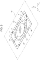
FIG. 3 is a perspective view showing a lower face side of the driving device; -
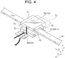
FIG. 4 is a perspective view showing a yoke part and a magnetic element of the driving device; -
FIG. 5 is a perspective view showing a driving device according to a second example of the present invention; -
FIG. 6 is a perspective view showing a lower face side of the driving device; -
FIG. 7 is a perspective view showing a main part of the driving device; -
FIG. 8 is a perspective view showing a driving device according to a third example of the present invention; and -
FIG. 9 is a perspective view showing a lower face side of the driving device. - An embodiment of the present invention will be described below. A driving device according to an embodiment of the present invention includes a first driven part, a second driven part that rotatably supports the first driven part via a first shaft part, a base part that rotatably supports the second driven part via a second shaft part, a magnetic element provided on the second driven part, and a yoke part including a pair of ends and configured to rotate the first driven part via the second driven part by applying the magnetic field generated at these ends to the magnetic element. The yoke part is configured such that the pair of ends thereof sandwiches a reference plane on which the base part extends.
- Since the magnetic element is provided on the second driven part, the first driven part and the ends of the yoke part are prevented from interfering with each other, and, by disposing the magnetic element close to the ends of the yoke part, the entire device can be downsized. Further, the first driven part and the ends of the yoke part are prevented from interfering with each other even when the driving force is increased by disposing the magnetic element close to the ends of the yoke part and the swing angle of the first driven part is increased. In this instance, when a magnetic field having a frequency corresponding to the resonance frequency of the first driven part is generated at the ends of the yoke part, the swing angle of the first driven part can be increased while the swing angle of the second driven part can be reduced, thereby preventing the interference between the second driven part and the ends of the yoke part. In this way, it is possible to prevent the interference between the components while obtaining a large driving force, and the swing angle of the first driven part can be increased.
- The magnetic element and the ends of the yoke part are arranged at positions corresponding to each other in the axis direction of the first shaft part (or the second shaft part). In order to obtain a large driving force, it is preferable that their positions in the axis direction correspond to each other; however, for convenience of arrangement of other components, for example, they may be positioned slightly displaced from each other in the axis direction.
- It is preferable that the magnetic element is disposed on a closest part on the second driven part closest to the base part. This facilitates application of the magnetic field generated at the ends of the yoke part onto the magnetic element, thereby obtaining a large driving force.
- It is preferable that the magnetic element is arranged at the central part of the second driven part in the axis direction of the second shaft part. This can prevent a movement such as twisting with respect to the rotation around the second shaft part as the axis direction during the driving of the second driven part.
- The first driven part is formed in a circular plate shape or an elliptical plate shape, and the magnetic element is arranged on the second driven part at a position displaced in the axis direction of the first shaft part with respect to the closest part where the base part is closest to the first driven part. Consequently, the first driven part can be easily disposed close to the base part at the closest part, and the surface area of the first driven part can be increased.
- Further, at a position corresponding to the closest part, the second driven part has a width in a facing direction in which the base part and the first driven part face each other that is smaller than that of rest of the second driven part. Consequently, in a case where the first driven part is a mirror, it is possible to prevent the light from being blocked by the second driven part at the closest part.
- It is preferable that the magnetic elements are arranged on both sides of the second driven part in the intersecting direction intersecting the axis direction of the second shaft part. Consequently, a driving force can be applied to the second driven part from both sides in the intersecting direction.
- It is preferable that the driving device further includes a coil part, and the wiring part forming the coil part includes an axially extending part that extends along the base part and extends in the axis direction of the second shaft part, and the yoke part is formed in an opened annular shape that surrounds the axially extending part from both sides of the reference plane and from a side opposite to the second driven part and that is opened on the second driven part side. Consequently, when a current flows through the axially extending part, the lines of magnetic force concentrate at the yoke part, and this can facilitate application of the magnetic field onto the magnetic element on the second driven part side where it is opened.
- It is preferable that the first shaft part and the second shaft part are arranged coaxially. Consequently, the driving force applied to the second driven part can be easily transmitted to the first driven part.
- It is preferable that the driving device further includes a coil part and a pedestal which is made of a non-magnetic material and to which the base part is joined, and that the coil part is disposed on the pedestal or in the pedestal. Consequently, by disposing the coil part on the pedestal or in the pedestal, the entire driving device can be downsized.
- The driving device according to another embodiment of the present invention includes a driving device including a movable part, a base part that rotatably supports the movable part via a shaft part, a magnetic element provided on the movable part, and a driving section that includes a coil part and that is configured to rotate the movable part by applying, to the magnetic element, a magnetic field generated by the coil part. The coil part is formed by a wiring extending along the base part.
- Since the coil part is constituted of the wiring that extends along the base part, the entire driving device can be downsized as compared with the configuration in which the coil part is arranged side by side with respect to the base part.
- Each example of the present invention will be described in detail below. With respect to a second example and a third example, the same components and the components having the same function as those described in a first example are designated by the same reference signs as those in the first example, and the description thereof is omitted.
- As shown in
FIGS. 1 to 3 , adriving device 1A of this example is an optical deflector including amirror 2 as a first driven part, a rotary frame 3 as a second driven part, a base part 4, twomagnetic elements yoke parts inner torsion bar 20 as a first shaft part, and anouter torsion bar 30 as a second shaft part. Thedriving device 1A is used, for example, for a detection device that is mounted on a vehicle to detect a distance from another vehicle, an installation or the like by transmitting and receiving light such as infrared rays. - In this example, the
inner torsion bar 20 and theouter torsion bar 30 are arranged coaxially, wherein an extending direction (axis direction) thereof corresponds to an X direction, and a plate thickness direction of themirror 2 corresponds to a Z direction. A direction orthogonal to both the X direction and the Z direction is a Y direction, that is, themirror 2 extends along the XY plane. - The
mirror 2 is formed in an elliptical plate shape with its longitudinal direction corresponding to the X direction, and asurface 21 thereof is a reflective face formed by mirror finishing. Theinner torsion bars 20 are connected to both ends of themirror 2 in the X direction. - The rotary frame 3 is formed in an elliptical annular shape when viewed from the Z direction with its longitudinal direction corresponding to the X direction, and it extends along the XY plane so as to surround the
mirror 2. The both ends of the rotary frame 3 in the X direction are provided with theinner torsion bars 20 connected to inner sides of said both ends and theouter torsion bars 30 connected to outer sides of said both ends. That is, themirror 2 is rotatably supported by the rotary frame 3 via theinner torsion bars 20. - The base part 4 is formed in a rectangular frame shape when viewed from the Z direction with its longitudinal direction corresponding to the X direction, and it extends along the XY plane so as to surround the rotary frame 3. The
outer torsion bars 30 are connected to an inner side of the base part 4 on both ends in the X direction and on central parts in the Y direction. That is, the rotary frame 3 is rotatably supported by the base part 4 via the outer torsion bars 30. Herein, a plane on which the base part 4 extends is defined as a reference plane S1. The reference plane S1 is arranged along the XY plane, and themirror 2 and the rotary frame 3 also extend along the reference plane S1. - The
mirror 2, the rotary frame 3 and theinner torsion bars 20 as described above constitute a movable part, and the movable part is rotatably supported by the base part 4 via the outer torsion bars 30. - The
magnetic elements central parts magnetic elements central parts central parts FIG. 4 , themagnetic elements - The coil part 6 is formed by a
wiring 61 extending along the base part 4. That is, thewiring 61 is wound in a rectangular shape with its longitudinal direction corresponding to the X direction, thereby forming the coil part 6. The number of turns of thewiring 61 wound along the base part 4 is appropriately set according to various conditions such as driving force to be applied to the second driven part, a space on the base part 4 and an allowable current for thewiring 61. In this example, the coil part 6 is provided on thelower face 42 of the base part 4, but it may be provided on theupper face 41, or it may be provided on both of theupper face 41 and thelower face 42. Herein, theupper face 41 of the base part 4 is a face that faces the same side as the surface (reflective face) 21 of themirror 2. - An appropriate power source is connected to both ends of the
wiring 61 to supply electric power as needed. That is, a voltage having a frequency corresponding to the resonance frequency of themirror 2 is applied to the both ends of thewiring 61 to generate a magnetic field. Thewiring 61 includes axially extendingparts - The
yoke parts axially extending parts magnetic elements yoke parts magnetic elements - Each of the
yoke parts part 71 extending along the XY plane on the upper side in the Z direction (i.e., thesurface 21 side) of theaxially extending part part 72 extending along the XY plane on the lower side in the Z direction of theaxially extending part part 73 extending along the ZX plane on the outside of theaxially extending part 611, 612 (i.e., on the side opposite to the rotary frame 3) and connecting the first extendingpart 71 and the second extendingpart 72. - That is, the
yoke parts axially extending parts yoke parts part 71 and an inner end of the second extendingpart 72 correspond to a pair ofends yoke parts ends - The coil part 6 and the
yoke parts magnetic elements - The pedestal 8 is configured such that the base part 4 is fixed thereto to support the base part 4, and an upper face thereof (i.e., a face thereof on the base part 4 side) is provided with a recessed part (accommodating part) for accommodating the coil part 6. That is, the coil part 6 is arranged inside the pedestal 8. A recessed part (accommodating part) capable of accommodating the coil part 6 may be formed on the lower face (i.e., a face on the pedestal 8 side) of the base part 4.
- Now, the details of the driving force applied to the
mirror 2 and the rotary frame 3 will be described. When a current flows through the coil part 6 and a magnetic field is generated, lines of magnetic force are to pass through theyoke parts ends 74, 75 (i.e., along the Z direction). Further, the magnetic poles of themagnetic elements - Due to these magnetic interactions, the rotary frame 3 provided with the
magnetic elements outer torsion bars 30 arranged along the X direction is applied with the driving force that rotates the rotary frame 3 with respect to the X direction as the axis direction. The driving force generated at themagnetic element 5A and the driving force generated at themagnetic element 5B have the same direction of rotation. - Since the current flowing through the coil part 6 has a frequency corresponding to the resonance frequency of the
mirror 2, the rotary frame 3 does not rotate significantly even when the driving force is applied. It is preferable that the resonance frequency of themirror 2 and the resonance frequency of the rotary frame 3 are different from each other, and it is more preferable that one of the resonance frequencies is not an integer multiple of the other one of the resonance frequencies. - When the rotation of the rotary frame 3 is transmitted to the
mirror 2 via theinner torsion bars 20, themirror 2 rotates more than the rotary frame 3, since the frequency of the rotation of the rotary frame 3 substantially corresponds with the resonance frequency of themirror 2. In this manner, the driving force applied to the rotary frame 3 is transmitted to themirror 2. - According to the above-described configuration, the
magnetic elements mirror 2 and theends yoke parts magnetic elements ends - Further, since the
magnetic elements mirror 2 and theends mirror 2 is increased by disposing themagnetic elements ends yoke parts ends mirror 2, the swing angle of themirror 2 can be increased while the swing angle of the rotary frame 3 can be made smaller than the swing angle of themirror 2, thereby preventing the interference between themirror 2 and theends mirror 2 can be increased. - Furthermore, the
magnetic elements central parts ends yoke parts magnetic elements mirror 2 can be increased. - Further, the
magnetic elements central parts outer torsion bars 30 as the axis direction during the driving of the rotary frame 3. - Further, the two
magnetic elements - Further, the
yoke parts axially extending parts yoke parts axially extending parts ends yoke parts magnetic elements - Further, since the
inner torsion bars 20 and theouter torsion bars 30 are arranged coaxially, the driving force applied to the rotary frame 3 can be easily transmitted to themirror 2. - Further, since the coil part 6 is arranged on the pedestal 8, the
entire driving device 1A can be downsized. - Further, since the coil part 6 is constituted of the
wiring 61 extending along the base part 4, theentire driving device 1A can be downsized as compared with the configuration in which the coil part is arranged side by side with respect to the base part. - As shown in
FIGS. 5 and6 , adriving device 1B of this example is an optical deflector including amirror 2 as a first driven part, arotary frame 3B as a second driven part, abase part 4B, four magnetic elements 5C-5F, acoil part 6B, four yoke parts 7C-7F, a pedestal, aninner torsion bar 20 as a first shaft part, and anouter torsion bar 30 as a second shaft part. Although the pedestal is not shown inFIGS. 5 and6 , the pedestal of thedriving device 1B is the same as the pedestal 8 of thedriving device 1A of the first example. In this example also, the X direction, the Y direction and the Z direction are the same as those in the first example. - The
rotary frame 3B is formed in a hexagonal annular shape having vertices at both ends in the X direction when viewed from the Z direction, and it extends along the XY plane so as to surround themirror 2. That is, therotary frame 3B includes four inclined parts 33-36 extending so as to approach themirror 2 in the X direction and approach thebase part 4B in the Y direction, and it also includesparallel parts - An intersection of the
inclined part 33 and theinclined part 34 corresponds to one end of therotary frame 3B in the X direction, where theinner torsion bar 20 is connected to the inner side and theouter torsion bar 30 is connected to the outer side. Further, an intersection of theinclined part 35 and theinclined part 36 corresponds to the other end of therotary frame 3B in the X direction, where theinner torsion bar 20 is connected to the inner side and theouter torsion bar 30 is connected to the outer side. - The
parallel part 37 extends so as to connect theinclined part 33 and theinclined part 35, and theparallel part 38 extends so as to connect theinclined part 34 and theinclined part 36. As shown inFIG. 7 , theparallel parts convex parts closest parts mirror 2 located closest to thebase part 4B. - Further, the widths (dimensions in the Y direction) of the
parallel parts rotary frame 3B at the positions corresponding to theclosest parts rotary frame 3B. - The
base part 4B includesconvex parts 43 corresponding to theconvex parts base part 4B is formed so as to recede from themirror 2 at theconvex parts 43. Further, thecoil part 6B is arranged along thebase part 4B and similarly includes convex parts. - The magnetic elements 5C-5F are arranged at intersections 391-394 of the inclined parts 33-36 and the
parallel parts closest parts - The yoke parts 7C-7F correspond to the magnetic elements 5C-5F, respectively, and are arranged so as to avoid the
convex parts 43 of thebase part 4B. The shape of the yoke parts 7C-7F is the same as the shape of theyoke parts - According to the above-described configuration, as in the case of the first example, the magnetic elements 5C-5F are provided on the
rotary frame 3B, thus the entire device can be downsized and the swing angle of themirror 2 can be increased. In addition, thecoil part 6B is constituted of thewiring 61 extending along thebase part 4B, thus theentire driving device 1B can be downsized. - Further, the magnetic elements 5C-5F are arranged so as to be displaced in the X direction with respect to the
closest parts mirror 2 can be easily disposed close to thebase part 4B at theclosest parts mirror 2 can be increased. - Further, the
rotary frame 3B includes theconvex parts mirror 2, and the widths of theparallel parts mirror 2 from being blocked by therotary frame 3B at theclosest parts - As shown in
FIGS. 8 and9 , a driving device 1C of this example is an optical deflector including amirror 2, a base part 4, twomagnetic elements yoke parts torsion bar 40. That is, the driving device 1C corresponds to thedriving device 1A of the first example except the rotary frame 3 and theinner torsion bars 20 are omitted and themirror 2 is rotatably supported by the base part 4 via the torsion bars 40. In addition, themagnetic elements closest parts mirror 2. Although the pedestal is not shown inFIGS. 8 and9 , the pedestal of the driving device 1C is the same as the pedestal 8 of thedriving device 1A of the first example. In this example also, the X direction, the Y direction and the Z direction are the same as those in the first example. - According to the above-described configuration, as in the case of the first example, the coil part 6 is constituted of the
wiring 61 extending along the base part 4, thus the entire driving device 1C can be downsized. Further, themagnetic elements closest parts mirror 2, and this facilitates application of the magnetic field generated at the ends of theyoke parts magnetic elements - The present invention is not limited to the examples described above, but includes other configurations and the like that can achieve the object of the present invention, and the following modifications and the like are also included in the present invention.
- For example, in the first to third examples, the
mirror 2 has an elliptical plate shape, but the mirror as the first driven part may have other shapes such as a circular plate shape or a polygonal plate shape, or may have any shape appropriate for its application. - Further, in the first to third examples described above, the
yoke parts 7A-7F have the opened annular shape that surrounds the axially extending part of the coil part and that is opened on the rotary frame side; however, the shape and the arrangement of the yoke parts are not limited to these as long as the yoke parts are configured so as to allow the magnetic flux to pass therethrough upon generation of the magnetic field by the coil part. - Further, in the first to third examples described above, the magnetic elements are arranged on both sides in the Y direction with respect to the
mirror 2; however, the magnetic element may be arranged only on one side in the Y direction with respect to themirror 2. In this case, the yoke may also be arranged only on one side in the Y direction with respect to themirror 2. - Further, in the first example and the second example described above, the
inner torsion bars 20 and theouter torsion bars 30 are arranged coaxially; however, the extending direction of theinner torsion bars 20 may intersect the extending direction of the outer torsion bars 30. That is, the torsion bars may have other configurations as long as they allow to transmit the rotation of therotary frame 3, 3B to themirror 2 when therotary frame 3, 3B is rotated. - Further, in the third example, the
magnetic elements closest parts mirror 2; however, themagnetic elements closest parts mirror 2. - Although the preferred configurations and methods and such for carrying out the present invention have been described above, the present invention is not limited to these. That is, although the present invention is mainly illustrated and described with respect to specific examples, those skilled in the art can make modifications to the above-described examples regarding the shape, materials, quantities and other detailed configurations without departing from the scope of the technical idea and purpose of the present invention. Therefore, since the description limiting the shape, material, etc. disclosed above is merely an example for facilitating the understanding of the present invention and does not limit the present invention, the description of name of a member without a part or all of the limitation of the shape, materials, etc., is within the present invention.
-
- 1A-1C
- driving device
- 2
- mirror (first driven part)
- 22, 23
- closest part
- 3, 3B
- rotary frame (second driven part)
- 31, 32
- central part (closest part)
- 4, 4B
- base part
- 5A-5F
- magnetic element
- 6, 6B
- coil part
- 61
- wiring
- 611, 612
- axially extending part
- 7A-7F
- yoke part
- 8
- pedestal
- 20
- inner torsion bar (first shaft part)
- 30
- outer torsion bar (second shaft part)
- 40
- torsion bar (shaft part)
- S1
- reference plane
Claims (11)
- A driving device comprising:a first driven part;a second driven part that rotatably supports the first driven part via a first shaft part;a base part that rotatably supports the second driven part via a second shaft part;a magnetic element provided on the second driven part; anda yoke part including a pair of ends and configured to rotate the first driven part via the second driven part by applying a magnetic field generated at the ends to the magnetic element, whereinthe yoke part is arranged to sandwich, between the pair of ends, a reference plane on which the base part extends.
- The driving device as claimed in claim 1, wherein a swing angle of rotation of the first driven part is greater than a swing angle of rotation of the second driven part.
- The driving device as claimed in claim 1 or 2, wherein the magnetic element is disposed at a closest part of the second driven part with respect to the base part.
- The driving device as claimed in one of claims 1-3, wherein the magnetic element is disposed at a central part, in an axis direction of the second shaft part, of the second driven part.
- The driving device as claimed in claim 1 or 2, whereinthe first driven part is formed in a circular plate shape or an elliptical plate shape, andthe magnetic element is disposed at a position on the second driven part that is displaced in an axis direction of the first shaft part with respect to a closest part where the base part is closest to the first driven part.
- The driving device as claimed in claim 5, wherein, at a position corresponding to the closest part, the second driven part has a width in a facing direction in which the base part and the first driven part face each other that is smaller than that of rest of the second driven part.
- The driving device as claimed in one of claims 1-6, wherein the magnetic elements are arranged on both sides of the second driven part in a direction intersecting an axis direction of the second shaft part.
- The driving device as claimed in one of claims 1-7, further comprising a coil part, whereina wiring part forming the coil part includes an axially extending part that extends along the base part and extends in an axis direction of the second shaft part, andthe yoke part is formed in an opened annular shape that surrounds the axially extending part from both sides of the reference plane and from a side opposite to the second driven part and that is opened on the second driven part side.
- The driving device as claimed in one of claims 1-8, wherein the first shaft part and the second shaft part are arranged coaxially.
- The driving device as claimed in one of claims 1-9, further comprising:a coil part; anda pedestal which is made of a non-magnetic material and to which the base part is joined, whereinthe coil part is disposed on the pedestal or in the pedestal.
- A driving device comprising:a movable part;a base part that rotatably supports the movable part via a shaft part;a magnetic element provided on the movable part; anda driving section that includes a coil part and that rotates the movable part by applying, to the magnetic element, a magnetic field generated by the coil part, whereinthe coil part is formed by a wiring extending along the base part.
Applications Claiming Priority (2)
| Application Number | Priority Date | Filing Date | Title |
|---|---|---|---|
| JP2018225145 | 2018-11-30 | ||
| PCT/JP2019/044654 WO2020110746A1 (en) | 2018-11-30 | 2019-11-14 | Driving device |
Publications (2)
| Publication Number | Publication Date |
|---|---|
| EP3889100A1 true EP3889100A1 (en) | 2021-10-06 |
| EP3889100A4 EP3889100A4 (en) | 2022-08-10 |
Family
ID=70854118
Family Applications (1)
| Application Number | Title | Priority Date | Filing Date |
|---|---|---|---|
| EP19890889.9A Withdrawn EP3889100A4 (en) | 2018-11-30 | 2019-11-14 | Driving device |
Country Status (4)
| Country | Link |
|---|---|
| US (1) | US20210173198A1 (en) |
| EP (1) | EP3889100A4 (en) |
| JP (1) | JP7340540B2 (en) |
| WO (1) | WO2020110746A1 (en) |
Family Cites Families (12)
| Publication number | Priority date | Publication date | Assignee | Title |
|---|---|---|---|---|
| JPH0682711A (en) * | 1992-08-31 | 1994-03-25 | Matsushita Electric Works Ltd | Scan mirror drive |
| JP3848249B2 (en) * | 2001-12-28 | 2006-11-22 | キヤノン株式会社 | Oscillator device |
| JP2005148339A (en) * | 2003-11-14 | 2005-06-09 | Canon Inc | Optical deflector |
| JP5064864B2 (en) * | 2007-04-02 | 2012-10-31 | キヤノン株式会社 | Optical deflection apparatus, image forming apparatus, and driving method of optical deflection apparatus |
| KR20100063997A (en) * | 2008-12-04 | 2010-06-14 | 삼성전자주식회사 | Laser scanning unit and method of detecting scanning sync signal |
| JP2011133745A (en) * | 2009-12-25 | 2011-07-07 | Toyota Central R&D Labs Inc | Optical device |
| JP2012208395A (en) | 2011-03-30 | 2012-10-25 | Nec Corp | Magnetic force drive unit, optical scanner and image display |
| WO2013175663A1 (en) * | 2012-05-22 | 2013-11-28 | 日本電気株式会社 | Optical scanning element and optical scanning device |
| JP5976132B2 (en) * | 2013-02-08 | 2016-08-23 | パイオニア株式会社 | Actuator |
| JP6349229B2 (en) * | 2014-10-23 | 2018-06-27 | スタンレー電気株式会社 | Biaxial optical deflector and manufacturing method thereof |
| EP3764147B1 (en) * | 2018-03-09 | 2023-03-22 | Pioneer Corporation | Reflector with actuator, optical scanner, and mirror actuator |
| WO2019208375A1 (en) * | 2018-04-27 | 2019-10-31 | パイオニア株式会社 | Light deflector |
-
2019
- 2019-11-14 WO PCT/JP2019/044654 patent/WO2020110746A1/en not_active Ceased
- 2019-11-14 US US17/272,266 patent/US20210173198A1/en not_active Abandoned
- 2019-11-14 EP EP19890889.9A patent/EP3889100A4/en not_active Withdrawn
- 2019-11-14 JP JP2020558329A patent/JP7340540B2/en active Active
Also Published As
| Publication number | Publication date |
|---|---|
| JPWO2020110746A1 (en) | 2021-11-04 |
| JP7340540B2 (en) | 2023-09-07 |
| US20210173198A1 (en) | 2021-06-10 |
| WO2020110746A1 (en) | 2020-06-04 |
| EP3889100A4 (en) | 2022-08-10 |
Similar Documents
| Publication | Publication Date | Title |
|---|---|---|
| US9997975B2 (en) | Driving apparatus | |
| US8498036B2 (en) | Optical scanning apparatus and image forming apparatus | |
| US11252310B2 (en) | Camera module, electronic device and photographing method | |
| JP6053277B2 (en) | Magnetic actuator and micromirror and mirror system using the same | |
| EP3006395B1 (en) | Drive device | |
| JP2008122470A (en) | Lens driving device and manufacturing method thereof | |
| JP6039916B2 (en) | Potential measurement device | |
| JP2013224904A5 (en) | ||
| US20180314056A1 (en) | Micromechanical constituent and method for adjusting an adjustable element | |
| JP5252872B2 (en) | Planar type electromagnetic actuator | |
| KR100941798B1 (en) | Scanning micromirrors | |
| JP4968760B1 (en) | Actuator | |
| US20210173198A1 (en) | Driving device | |
| CN112558290A (en) | Driver and optical scanning device | |
| KR102941778B1 (en) | Reflector scanner | |
| US11340446B2 (en) | Actuator | |
| JP2012208395A (en) | Magnetic force drive unit, optical scanner and image display | |
| JP2011128173A (en) | Mems actuator | |
| JP7507948B2 (en) | Drive unit | |
| JP5806089B2 (en) | Planar type electromagnetic actuator | |
| JP2013101199A5 (en) | ||
| Han et al. | Biaxial vector-graphic scanning micromirror using radial magnetic field | |
| JP3016820B2 (en) | Steering electromagnetic device | |
| JP2013101198A5 (en) | ||
| CA2571681A1 (en) | Optical scanner |
Legal Events
| Date | Code | Title | Description |
|---|---|---|---|
| STAA | Information on the status of an ep patent application or granted ep patent |
Free format text: STATUS: THE INTERNATIONAL PUBLICATION HAS BEEN MADE |
|
| PUAI | Public reference made under article 153(3) epc to a published international application that has entered the european phase |
Free format text: ORIGINAL CODE: 0009012 |
|
| STAA | Information on the status of an ep patent application or granted ep patent |
Free format text: STATUS: REQUEST FOR EXAMINATION WAS MADE |
|
| 17P | Request for examination filed |
Effective date: 20210223 |
|
| AK | Designated contracting states |
Kind code of ref document: A1 Designated state(s): AL AT BE BG CH CY CZ DE DK EE ES FI FR GB GR HR HU IE IS IT LI LT LU LV MC MK MT NL NO PL PT RO RS SE SI SK SM TR |
|
| DAV | Request for validation of the european patent (deleted) | ||
| DAX | Request for extension of the european patent (deleted) | ||
| A4 | Supplementary search report drawn up and despatched |
Effective date: 20220711 |
|
| RIC1 | Information provided on ipc code assigned before grant |
Ipc: G02B 26/10 20060101ALI20220705BHEP Ipc: G02B 26/08 20060101ALI20220705BHEP Ipc: B81B 3/00 20060101AFI20220705BHEP |
|
| STAA | Information on the status of an ep patent application or granted ep patent |
Free format text: STATUS: EXAMINATION IS IN PROGRESS |
|
| 17Q | First examination report despatched |
Effective date: 20240819 |
|
| STAA | Information on the status of an ep patent application or granted ep patent |
Free format text: STATUS: THE APPLICATION HAS BEEN WITHDRAWN |
|
| 18W | Application withdrawn |
Effective date: 20241002 |