EP3889086A1 - Sheet stacking apparatus, sheet processing apparatus, and image forming system - Google Patents
Sheet stacking apparatus, sheet processing apparatus, and image forming system Download PDFInfo
- Publication number
- EP3889086A1 EP3889086A1 EP21162516.5A EP21162516A EP3889086A1 EP 3889086 A1 EP3889086 A1 EP 3889086A1 EP 21162516 A EP21162516 A EP 21162516A EP 3889086 A1 EP3889086 A1 EP 3889086A1
- Authority
- EP
- European Patent Office
- Prior art keywords
- sheet
- stacking
- abutting portion
- tray
- sheets
- Prior art date
- Legal status (The legal status is an assumption and is not a legal conclusion. Google has not performed a legal analysis and makes no representation as to the accuracy of the status listed.)
- Pending
Links
- 238000012545 processing Methods 0.000 title claims description 25
- 238000000034 method Methods 0.000 claims description 12
- 230000008569 process Effects 0.000 claims description 8
- 230000033001 locomotion Effects 0.000 description 64
- 238000001514 detection method Methods 0.000 description 27
- 238000012805 post-processing Methods 0.000 description 22
- 230000007246 mechanism Effects 0.000 description 15
- 238000007599 discharging Methods 0.000 description 14
- 238000011144 upstream manufacturing Methods 0.000 description 13
- 238000010586 diagram Methods 0.000 description 6
- 230000015572 biosynthetic process Effects 0.000 description 4
- 230000004048 modification Effects 0.000 description 3
- 238000012986 modification Methods 0.000 description 3
- 230000005540 biological transmission Effects 0.000 description 2
- 230000003139 buffering effect Effects 0.000 description 2
- 230000000694 effects Effects 0.000 description 2
- 230000005484 gravity Effects 0.000 description 2
- 238000010438 heat treatment Methods 0.000 description 2
- 239000000463 material Substances 0.000 description 2
- 238000007639 printing Methods 0.000 description 2
- 230000001105 regulatory effect Effects 0.000 description 2
- 230000006835 compression Effects 0.000 description 1
- 238000007906 compression Methods 0.000 description 1
- 230000001276 controlling effect Effects 0.000 description 1
- 239000011521 glass Substances 0.000 description 1
- 229910052736 halogen Inorganic materials 0.000 description 1
- 150000002367 halogens Chemical class 0.000 description 1
- 238000007645 offset printing Methods 0.000 description 1
- 230000003287 optical effect Effects 0.000 description 1
- 239000002245 particle Substances 0.000 description 1
- 230000002093 peripheral effect Effects 0.000 description 1
- 238000004080 punching Methods 0.000 description 1
Images




Classifications
-
- B—PERFORMING OPERATIONS; TRANSPORTING
- B65—CONVEYING; PACKING; STORING; HANDLING THIN OR FILAMENTARY MATERIAL
- B65H—HANDLING THIN OR FILAMENTARY MATERIAL, e.g. SHEETS, WEBS, CABLES
- B65H31/00—Pile receivers
- B65H31/04—Pile receivers with movable end support arranged to recede as pile accumulates
- B65H31/08—Pile receivers with movable end support arranged to recede as pile accumulates the articles being piled one above another
- B65H31/10—Pile receivers with movable end support arranged to recede as pile accumulates the articles being piled one above another and applied at the top of the pile
-
- B—PERFORMING OPERATIONS; TRANSPORTING
- B65—CONVEYING; PACKING; STORING; HANDLING THIN OR FILAMENTARY MATERIAL
- B65H—HANDLING THIN OR FILAMENTARY MATERIAL, e.g. SHEETS, WEBS, CABLES
- B65H29/00—Delivering or advancing articles from machines; Advancing articles to or into piles
- B65H29/16—Delivering or advancing articles from machines; Advancing articles to or into piles by contact of one face only with moving tapes, bands, or chains
-
- B—PERFORMING OPERATIONS; TRANSPORTING
- B65—CONVEYING; PACKING; STORING; HANDLING THIN OR FILAMENTARY MATERIAL
- B65H—HANDLING THIN OR FILAMENTARY MATERIAL, e.g. SHEETS, WEBS, CABLES
- B65H29/00—Delivering or advancing articles from machines; Advancing articles to or into piles
- B65H29/52—Stationary guides or smoothers
-
- B—PERFORMING OPERATIONS; TRANSPORTING
- B65—CONVEYING; PACKING; STORING; HANDLING THIN OR FILAMENTARY MATERIAL
- B65H—HANDLING THIN OR FILAMENTARY MATERIAL, e.g. SHEETS, WEBS, CABLES
- B65H31/00—Pile receivers
- B65H31/26—Auxiliary devices for retaining articles in the pile
-
- B—PERFORMING OPERATIONS; TRANSPORTING
- B65—CONVEYING; PACKING; STORING; HANDLING THIN OR FILAMENTARY MATERIAL
- B65H—HANDLING THIN OR FILAMENTARY MATERIAL, e.g. SHEETS, WEBS, CABLES
- B65H43/00—Use of control, checking, or safety devices, e.g. automatic devices comprising an element for sensing a variable
- B65H43/08—Photoelectric devices
-
- G—PHYSICS
- G03—PHOTOGRAPHY; CINEMATOGRAPHY; ANALOGOUS TECHNIQUES USING WAVES OTHER THAN OPTICAL WAVES; ELECTROGRAPHY; HOLOGRAPHY
- G03G—ELECTROGRAPHY; ELECTROPHOTOGRAPHY; MAGNETOGRAPHY
- G03G15/00—Apparatus for electrographic processes using a charge pattern
- G03G15/65—Apparatus which relate to the handling of copy material
- G03G15/6529—Transporting
-
- B—PERFORMING OPERATIONS; TRANSPORTING
- B65—CONVEYING; PACKING; STORING; HANDLING THIN OR FILAMENTARY MATERIAL
- B65H—HANDLING THIN OR FILAMENTARY MATERIAL, e.g. SHEETS, WEBS, CABLES
- B65H2301/00—Handling processes for sheets or webs
- B65H2301/30—Orientation, displacement, position of the handled material
- B65H2301/36—Positioning; Changing position
- B65H2301/362—Positioning; Changing position of stationary material
-
- B—PERFORMING OPERATIONS; TRANSPORTING
- B65—CONVEYING; PACKING; STORING; HANDLING THIN OR FILAMENTARY MATERIAL
- B65H—HANDLING THIN OR FILAMENTARY MATERIAL, e.g. SHEETS, WEBS, CABLES
- B65H2301/00—Handling processes for sheets or webs
- B65H2301/30—Orientation, displacement, position of the handled material
- B65H2301/36—Positioning; Changing position
- B65H2301/363—Positioning; Changing position of material in pile
-
- B—PERFORMING OPERATIONS; TRANSPORTING
- B65—CONVEYING; PACKING; STORING; HANDLING THIN OR FILAMENTARY MATERIAL
- B65H—HANDLING THIN OR FILAMENTARY MATERIAL, e.g. SHEETS, WEBS, CABLES
- B65H2402/00—Constructional details of the handling apparatus
- B65H2402/30—Supports; Subassemblies; Mountings thereof
- B65H2402/32—Sliding support means
-
- B—PERFORMING OPERATIONS; TRANSPORTING
- B65—CONVEYING; PACKING; STORING; HANDLING THIN OR FILAMENTARY MATERIAL
- B65H—HANDLING THIN OR FILAMENTARY MATERIAL, e.g. SHEETS, WEBS, CABLES
- B65H2405/00—Parts for holding the handled material
- B65H2405/10—Cassettes, holders, bins, decks, trays, supports or magazines for sheets stacked substantially horizontally
- B65H2405/11—Parts and details thereof
- B65H2405/111—Bottom
- B65H2405/1115—Bottom with surface inclined, e.g. in width-wise direction
- B65H2405/11151—Bottom with surface inclined, e.g. in width-wise direction with surface inclined upwardly in transport direction
-
- B—PERFORMING OPERATIONS; TRANSPORTING
- B65—CONVEYING; PACKING; STORING; HANDLING THIN OR FILAMENTARY MATERIAL
- B65H—HANDLING THIN OR FILAMENTARY MATERIAL, e.g. SHEETS, WEBS, CABLES
- B65H2405/00—Parts for holding the handled material
- B65H2405/10—Cassettes, holders, bins, decks, trays, supports or magazines for sheets stacked substantially horizontally
- B65H2405/11—Parts and details thereof
- B65H2405/113—Front, i.e. portion adjacent to the feeding / delivering side
-
- B—PERFORMING OPERATIONS; TRANSPORTING
- B65—CONVEYING; PACKING; STORING; HANDLING THIN OR FILAMENTARY MATERIAL
- B65H—HANDLING THIN OR FILAMENTARY MATERIAL, e.g. SHEETS, WEBS, CABLES
- B65H2405/00—Parts for holding the handled material
- B65H2405/30—Other features of supports for sheets
- B65H2405/35—Means for moving support
- B65H2405/353—Means for moving support vertically
-
- B—PERFORMING OPERATIONS; TRANSPORTING
- B65—CONVEYING; PACKING; STORING; HANDLING THIN OR FILAMENTARY MATERIAL
- B65H—HANDLING THIN OR FILAMENTARY MATERIAL, e.g. SHEETS, WEBS, CABLES
- B65H2601/00—Problem to be solved or advantage achieved
- B65H2601/20—Avoiding or preventing undesirable effects
- B65H2601/25—Damages to handled material
- B65H2601/253—Damages to handled material to particular parts of material
- B65H2601/2531—Edges
-
- B—PERFORMING OPERATIONS; TRANSPORTING
- B65—CONVEYING; PACKING; STORING; HANDLING THIN OR FILAMENTARY MATERIAL
- B65H—HANDLING THIN OR FILAMENTARY MATERIAL, e.g. SHEETS, WEBS, CABLES
- B65H2601/00—Problem to be solved or advantage achieved
- B65H2601/50—Diminishing, minimizing or reducing
- B65H2601/52—Diminishing, minimizing or reducing entities relating to handling machine
- B65H2601/521—Noise
-
- B—PERFORMING OPERATIONS; TRANSPORTING
- B65—CONVEYING; PACKING; STORING; HANDLING THIN OR FILAMENTARY MATERIAL
- B65H—HANDLING THIN OR FILAMENTARY MATERIAL, e.g. SHEETS, WEBS, CABLES
- B65H2701/00—Handled material; Storage means
- B65H2701/10—Handled articles or webs
- B65H2701/11—Dimensional aspect of article or web
- B65H2701/113—Size
- B65H2701/1131—Size of sheets
-
- B—PERFORMING OPERATIONS; TRANSPORTING
- B65—CONVEYING; PACKING; STORING; HANDLING THIN OR FILAMENTARY MATERIAL
- B65H—HANDLING THIN OR FILAMENTARY MATERIAL, e.g. SHEETS, WEBS, CABLES
- B65H2701/00—Handled material; Storage means
- B65H2701/10—Handled articles or webs
- B65H2701/13—Parts concerned of the handled material
- B65H2701/131—Edges
- B65H2701/1313—Edges trailing edge
-
- B—PERFORMING OPERATIONS; TRANSPORTING
- B65—CONVEYING; PACKING; STORING; HANDLING THIN OR FILAMENTARY MATERIAL
- B65H—HANDLING THIN OR FILAMENTARY MATERIAL, e.g. SHEETS, WEBS, CABLES
- B65H2801/00—Application field
- B65H2801/03—Image reproduction devices
-
- B—PERFORMING OPERATIONS; TRANSPORTING
- B65—CONVEYING; PACKING; STORING; HANDLING THIN OR FILAMENTARY MATERIAL
- B65H—HANDLING THIN OR FILAMENTARY MATERIAL, e.g. SHEETS, WEBS, CABLES
- B65H2801/00—Application field
- B65H2801/03—Image reproduction devices
- B65H2801/06—Office-type machines, e.g. photocopiers
-
- B—PERFORMING OPERATIONS; TRANSPORTING
- B65—CONVEYING; PACKING; STORING; HANDLING THIN OR FILAMENTARY MATERIAL
- B65H—HANDLING THIN OR FILAMENTARY MATERIAL, e.g. SHEETS, WEBS, CABLES
- B65H2801/00—Application field
- B65H2801/24—Post -processing devices
- B65H2801/27—Devices located downstream of office-type machines
Definitions
- the present invention relates to a sheet stacking apparatus that discharges a sheet, a sheet processing apparatus that process a sheet, and an image forming system that forms an image on a sheet.
- a stacking portion such as a tray that is lifted and lowered with sheets supported thereon is used.
- a sheet abutting portion that abuts the trailing end of the sheets discharged onto the stacking portion to regulate the sheet position is provided in a member positioned upstream of the stacking portion in a sheet discharge direction such as the casing of the image forming apparatus.
- Japanese Patent Laid-Open No. 2002-308507 discloses a configuration in which a belt member capable of abutting the trailing end of a sheet is disposed upstream of a discharge tray in a sheet discharge direction is provided. According to this document, as a result of the friction between the belt member and the sheet on the discharge tray, the belt member rotates in accordance with the lifting and lowering of the discharge tray.
- the belt member moves in accordance with the lifting and lowering of the discharge tray irrespective of the position of the discharge tray.
- the present invention provides a sheet stacking apparatus and an image forming apparatus that can suppress occurrence of an issue caused by rubbing of a sheet.
- the present invention in its first aspect provides a sheet stacking apparatus as specified in claims 1 through 15.
- a horizontal component of a sheet discharge direction in which a sheet stacking apparatus serving as a sheet discharge apparatus discharges a sheet will be referred to as a Y direction
- a sheet width direction of the sheet intersecting with the Y direction will be referred to as an X direction
- the vertical direction will be referred to as a Z direction.
- the X direction serves as a main scanning direction in image formation.
- the X direction, the Y direction, and the Z direction are preferably perpendicular to one another.
- FIG. 1 is a schematic view of an image forming system 1S according to a first embodiment.
- the image forming system 1S of the present embodiment includes an image forming apparatus 1, an image reading apparatus 2, a document feeding apparatus 3, and a post-processing apparatus 4.
- the image forming system 1S forms an image on a sheet serving as a recording material, and outputs the sheet after processing the sheet by the post-processing apparatus 4 if necessary.
- simple description of the operation of each apparatus will be given, and then the post-processing apparatus 4 will be described in detail.
- the document feeding apparatus 3 conveys a document placed on a document tray 18 to image reading portions 16 and 19.
- the image reading portions 16 and 19 are image sensors that read image information from respective document surfaces, and both surfaces of a document are read in one time of conveyance of the document.
- the document whose image information has been read is discharged onto a document discharge portion 20.
- the image reading apparatus 2 can read image information from a still document set on a platen glass, by reciprocating the image reading portion 16 by a driving device 17.
- Examples of the still document include documents such as booklet documents for which the document feeding apparatus 3 cannot be used.
- the image forming apparatus 1 is an electrophotographic apparatus including an image forming portion 1B of a direct transfer system.
- the image forming portion 1B includes a cartridge 8 including a photosensitive drum 9, and a laser scanner unit 15 disposed above the cartridge 8.
- the laser scanner unit 15 draws an electrostatic latent image on the surface of the photosensitive drum 9 by exposing the photosensitive drum 9 on the basis of image information.
- the electrostatic latent image born on the photosensitive drum 9 is developed into a toner image by charged toner particles, and the toner image is conveyed to a transfer portion where the photosensitive drum 9 and a transfer roller 10 face each other.
- the controller of the image forming apparatus 1 which is a printer controller that will be described later, executes an image forming operation by the image forming portion 1B on the basis of image information read by the image reading portions 16 and 19 or image information received from an external computer via a network.
- the image forming apparatus 1 includes a plurality of feeding apparatuses 6 that feed sheets serving as recording materials one by one at predetermined intervals.
- a sheet fed from a feeding apparatus 6 is conveyed to the transfer portion after the skew thereof is corrected by registration rollers 7, and in the transfer portion, the toner image born on the photosensitive drum 9 is transferred thereto.
- a fixing unit 11 is disposed downstream of the transfer portion in a sheet conveyance direction.
- the fixing unit 11 includes a rotary member pair that nips and conveys the sheet, and a heat generating member such as a halogen lamp for heating the toner image, and performs image fixing processing on the toner image on the sheet by heating and pressurizing the toner image.
- the sheet having passed through the fixing unit 11 is conveyed to the post-processing apparatus 4 via a horizontal conveyance portion 14.
- the sheet having passed through the fixing unit 11 is passed onto reverse conveyance rollers 12, switched back and conveyed by the reverse conveyance rollers 12, and conveyed to the registration rollers 7 again via a reconveyance portion 13. Then, an image is formed on a second surface of the sheet as a result of the sheet passing through the transfer portion and the fixing unit 11 again, and then the sheet is conveyed to the post-processing apparatus 4 via the horizontal conveyance portion 14.
- the image forming portion 1B described above is an example of an image forming unit that forms an image on a sheet, and an electrophotographic unit of an intermediate transfer system that transfers a toner image formed on a photosensitive member onto a sheet via an intermediate transfer member may be used therefor.
- an electrophotographic unit of an intermediate transfer system that transfers a toner image formed on a photosensitive member onto a sheet via an intermediate transfer member may be used therefor.
- a printing unit of an inkjet system or an offset printing system may be used as the image forming unit.
- the post-processing apparatus 4 includes a binding processing portion 4A that performs a binding process on sheets received from the image forming apparatus 1, and discharges the sheets as a sheet bundle.
- the post-processing apparatus 4 is also capable of simply discharging a sheet received from the image forming apparatus 1 without performing a binding process thereon.
- the binding processing portion 4A is an example of a processing unit that performs a process on a sheet, and a processing portion that performs a punching process, a processing portion that performs a folding process, or the like may be provided in place of or in addition to the binding processing portion 4A.
- the post-processing apparatus 4 includes an entry path 81, an in-body discharge path 82, a first discharge path 83, and a second discharge path 84 as conveyance paths for conveying a sheet, and an upper discharge portion 300Aand a lower discharge portion 300B are provided as discharge destinations onto which a sheet is discharged.
- the entry path 81 serves as a conveyance path through which a sheet is received from the outside of the post-processing apparatus 4 and conveyed.
- the first discharge path 83 serves as a first conveyance path through which the sheet received from the image forming apparatus 1 is discharged onto the upper discharge portion 300A.
- the in-body discharge path 82 serves as a second conveyance path which is branched from the first conveyance path and through which a sheet reversed and conveyed in the first conveyance path is conveyed toward the binding processing portion 4A.
- the second discharge path 84 serves as a third conveyance path through which the sheet conveyed to the binding processing portion 4A is discharged onto the lower discharge portion 300B.
- inlet rollers 21, pre-buffer rollers 22, an entrance sensor 27, and a lateral position detection sensor are disposed in the entry path 81.
- first discharge path 83 discharging/reversing rollers 24 serving as a reverse conveyance unit are disposed in the first discharge path 83.
- in-body discharge rollers 26, intermediate conveyance rollers 28, kick-out rollers 29, and a pre-intermediate supporting sensor 38 are disposed in the in-body discharge path 82.
- Each roller described above functions as a conveyance unit that conveys a sheet.
- bundle discharge rollers 36 are disposed in the second discharge path 84.
- the entrance sensor 27 and the pre-intermediate supporting sensor 38 each serve as an example of a sheet detection portion that detects passage of a sheet at a predetermined detection position in a conveyance path in a sheet processing apparatus.
- optical sensors that detect presence/absence of a sheet at the detection position by using light as will be described later can be used.
- a sheet conveyance path in the post-processing apparatus 4 will be described below.
- a buffering operation by a buffering portion 4B including the discharging/reversing rollers 24, and the detailed configuration and operation of the binding processing portion 4A will be described later.
- the sheet discharged from the horizontal conveyance portion 14 of the image forming apparatus 1 is received by the inlet rollers 21, and is conveyed toward the pre-buffer rollers 22 through the entry path 81.
- the entrance sensor 27 detects the sheet at a detection position between the inlet rollers 21 and the pre-buffer rollers 22.
- the lateral position detection sensor detects the position of the sheet in the sheet width direction (i.e., in the X direction) at a position between the detection position of the entrance sensor 27 and the pre-buffer rollers 22. In the description below, this position will be referred to as a lateral position of the sheet.
- the pre-buffer rollers 22 convey the sheet received from the inlet rollers 21 toward the first discharge path 83.
- the sheet conveyance speed of the pre-buffer rollers 22 is increased to a speed higher than the conveyance speed in the horizontal conveyance portion 14.
- the sheet conveyance speed of the inlet rollers 21 may be set to be higher than that in the horizontal conveyance portion 14, and the conveyance speed may be increased by the inlet rollers 21 upstream of the pre-buffer rollers 22.
- a one-way clutch is disposed between a conveyance roller of the horizontal conveyance portion 14 and a motor that drives the conveyance roller such that the conveyance roller idles when the sheet is pulled by the inlet rollers 21.
- the discharging/reversing rollers 24 discharge the sheet received from the pre-buffer rollers 22 onto the discharge portion 300A serving as a first discharge unit.
- the discharging/reversing rollers 24 decelerate to a predetermined discharge speed at a predetermined timing after the trailing end of the sheet has passed through the pre-buffer rollers 22.
- the discharging/reversing rollers 24 switch back and convey the sheet received from the pre-buffer rollers 22 toward the in-body discharge path 82.
- a non-return flap 23 is provided at a branching portion upstream of the discharging/reversing rollers 24 in the sheet discharge direction of the discharging/reversing rollers 24 where the entry path 81 and the in-body discharge path 82 branch from the first discharge path 83.
- the non-return flap 23 has a function of suppressing backward movement of the sheet switched back by the discharging/reversing rollers 24 into the entry path 81.
- the in-body discharge rollers 26, the intermediate conveyance rollers 28, and the kick-out rollers 29 disposed in the in-body discharge path 82 convey the sheet received from the discharging/reversing rollers 24 toward the binding processing portion 4A while passing the sheet onto one another.
- the pre-intermediate supporting sensor 38 detects the sheet at a position between the intermediate conveyance rollers 28 and the kick-out rollers 29.
- the binding processing portion 4A includes a stapler 51 serving as a binding unit of the present embodiment, and staples a predetermined position of the sheet bundle by the stapler 51 after aligning a plurality of sheets received from the in-body discharge path 82.
- the sheet bundle stapled by the binding processing portion 4A is passed onto the bundle discharge rollers 36 through the second discharge path 84 serving as a third conveyance path, and is discharged onto the discharge portion 300B by the bundle discharge rollers 36 serving as a second discharge unit.
- the upper and lower discharge portions 300A and 300B described above are each an example of a sheet stacking apparatus by which sheets are discharged and stacked.
- the discharge portions 300A and 300B each have a function of performing a discharge method of changing a discharge position of a sheet among a plurality of positions in the sheet width direction each time a predetermined number of sheets are discharged. This discharge method is also referred to as jog discharge.
- the discharge portions 300A and 300B are each provided with a tray 302 serving as a stacking portion configured to support sheets thereon.
- the trays 302 are each capable of moving up and down, that is, capable of being lifted and lowered, with respect to the apparatus body 40 of the post-processing apparatus 4 by a lifting mechanism 330 that will be described later.
- the tray 302 of the present embodiment moves up and down substantially in the vertical direction with respect to the apparatus body 40 as viewed from the front side of the image forming system 1S in FIG. 1 .
- the apparatus body 40 is a casing that includes a frame member and an exterior member of the post-processing apparatus 4, accommodates the binding processing portion 4A and a conveyance path, and movably supports the trays 302.
- the discharge portions 300A and 300B are each provided with a sheet surface detection sensor 305c serving as a detection portion for detecting a sheet stacking height, which is the upper surface position of sheets stacked on the tray 302.
- the sheet surface detection sensor 305c is configured such that the output signal thereof changes in accordance with the presence or absence of a sheet at a predetermined detection height.
- a photoelectric sensor of a transmission type utilizing laser light passing through a space above the tray 302 in the X direction at a detection height can be used as the sheet surface detection sensor 305c.
- the discharge portions 300A and 300B are each provided with a sheet presence/absence sensor 302f for detecting the presence or absence of a sheet on the tray 302.
- the sheet presence/absence sensor 302f is configured such that the output signal thereof changes in accordance with whether or not a sheet is present at a detection position on the tray 302.
- a flag member illustrated in FIG. 2A disposed to project from the tray 302 and a photo interrupter that detects swing of the flag member caused by being pressed by a sheet can be used as the sheet presence/absence sensor 302f.
- a controller of the post-processing apparatus 4 controls the lifting mechanism 330, which will be described later, on the basis of the detection results of the sheet surface detection sensors 305c and the sheet presence/absence sensors 302f, and thus controls the height of the trays 302 of the discharge portions 300A and 300B.
- the tray 302 is maintained at a predetermined home position.
- the lifting mechanism 330 is driven to lower the tray 302 by a predetermined amount in an A2 direction or a B2 direction.
- the lifting mechanism 330 is driven to lift the tray 302 in an A1 direction or a B 1 direction to return to the home position.
- the controller determines that it is impossible to discharge a sheet and stops the image forming operation.
- a distance in the Z direction in which a sheet discharged from the discharging/reversing rollers 24 or the bundle discharge rollers 36 falls onto the upper surface of a sheet on the tray 302 falls within a certain range. This suppresses falling of a sheet from the tray 302 and extreme misalignment of sheets, and thus contributes to maintaining a stable stacking state even in the case where the amount of stacked sheets is large.
- a discharge portion 300 serving as a sheet stacking apparatus according to the first embodiment will be described with reference to FIGS. 2A to 5B .
- the configuration of the discharge portion 300 that will be described below is suitably used as the upper discharge portion 300A in the post-processing apparatus 4 described above.
- the discharge portion 300 is also usable as the lower discharge portion 300B in the post-processing apparatus 4.
- FIG. 2A is a perspective view of the discharge portion 300
- FIG. 2B is a schematic view of the lifting mechanism 330 of the tray 302.
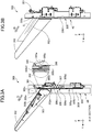
- FIG. 3A is a section view of the discharge portion 300 taken along a Y-Z plane at the position of a line A-A of FIG. 2A , which sections one of slide walls 306 that will be described later.
- FIG. 3B is a side view of the discharge portion 300 as viewed in the X direction.
- the discharge portion 300 includes a discharge roller pair 301, the tray 302, and the lifting mechanism 330.
- the discharge portion 300 includes a stacking wall 305g provided on a side wall 305 of the apparatus body 40 on one side in the Y direction (i.e., downstream side in a sheet discharge direction D), and slide walls 306 movable with respect to the stacking wall 305g.
- the discharge roller pair 301 is an example of a discharge unit that discharges sheets conveyed through the conveyance path in the apparatus body 40. Examples of the sheets include a sheet bundle formed by a binding process or the like.
- the discharge roller pair 301 may be used as the discharging/reversing rollers 24 or as the bundle discharge rollers 36 of FIG. 1 .
- the tray 302 is an example of a stacking portion on which sheets discharged by the discharge unit are stacked.
- the sheet discharge direction D a direction in which the discharge roller pair 301 nips a sheet and delivers out the sheet.
- the sheet discharge direction D is inclined upward in the Z direction toward a first side in the Y direction.
- the lifting/lowering direction of the tray 302 with respect to the apparatus body 40 is a direction intersecting with the horizontal plane, and is substantially the same as the Z direction in the present embodiment.
- the tray 302 has a supporting surface 302b serving as a supporting portion that supports a sheet. At least part of the supporting surface 302b is inclined upward in the Z direction toward the far side in the Y direction with respect to the apparatus body 40, that is, to the left in FIG. 2B . Due to the inclination of the supporting surface 302b, a sheet having been discharged from the discharge roller pair 301 and having fallen onto the tray 302 moves toward the side wall 305 of the apparatus body 40, and thus alignment of sheets on the tray 302 is improved. In addition, due to the inclination of the supporting surface 302b, the normal force that the sheets stacked on the tray 302 receive from the supporting surface 302b includes a Y-direction component toward the side wall 305.
- the tray 302 is coupled to the lifting mechanism 330 via a stay 303.
- the lifting mechanism 330 includes a lifting motor 331 serving as a drive source, and a belt drive transmission portion including a driving pulley 333, a driven pulley 334, and a lifting belt 336.
- the lifting belt 336 is stretched over the driving pulley 333 and the driven pulley 334 that are arranged with an interval therebetween in the Z direction.
- the driving pulley 333 and the driven pulley 334 are rotatably supported by the frame member of the apparatus body 40.
- the driving pulley 333 is driven to rotate by the lifting motor 331, and the driven pulley 334 rotates in accordance with the rotation of the lifting belt 336.
- the stay 303 is fixed to the lifting belt 336 via a fixing member 337.
- the tray 302 is lifted and lowered in accordance with the rotation of the lifting motor 331.
- the movement direction of the tray 302, that is, whether the tray 302 is lifted or lowered is determined in accordance with the rotation direction of the lifting motor 331, the movement amount of the tray 302 is determined in accordance with the rotation amount of the lifting motor 331, and the movement speed of the tray 302 is determined in accordance with the rotation speed of the lifting motor 331. Therefore, the controller of the post-processing apparatus 4 can control the lifting/lowering operation of the tray 302 by controlling the lifting motor 331.
- the lifting mechanism 330 of a belt type has been described as an example of a lifting unit in the present embodiment, a different lifting unit may be used.
- a configuration in which a motor and a pinion that is driven by the motor are disposed in the tray 302, the pinion is engaged with a rack provided in the apparatus body 40, and the tray 302 moves on the rack to ascend and descend may be employed.
- the lifting/lowering direction of the tray 302 by the lifting unit may be inclined with respect to the Z direction.
- the side wall 305 of the apparatus body 40 includes a stacking wall 305g capable of abutting the trailing end of sheets stacked on the tray 302, that is, the upstream end of the sheets in the sheet discharge direction D, and frame portions 305f respectively provided on two sides of the stacking wall 305g in the X direction.
- the stacking wall 305g mainly extends in the lifting/lowering direction of the tray 302 (i.e., the Z direction) and the sheet width direction (i.e., the X direction).
- the frame portions 305f are preferably members rigid enough to support the weight of the lifting mechanism 330, the tray 302, and sheets of the maximum stacking amount on the tray 302, such as members having L shapes as viewed in the Z direction.
- the stacking wall 305g is fixed to the frame member of the apparatus body 40, and does not move even in the case where the tray 302 is lifted or lowered. That is, the stacking wall 305g functions as a first abutting portion or first abutting member of the present embodiment that is capable of abutting or coming into contact with the trailing end of the sheets stacked on the stacking portion.
- the stacking wall 305g movable not in accordance with the lifting and lowering of the tray 302, for example, by making the stacking wall 305g openable and closable or attachable to and detachable from the frame portions 305f for access to the inside of the apparatus body 40.
- the stacking wall 305g includes a plurality of ribs 305b projecting to the first side in the Y direction, that is, to the downstream side in the sheet discharge direction D from a base surface extending in the X direction and the Z direction.
- the ribs 305b each extend in approximately the Z direction along the lifting/lowering direction of the tray 302. Ridge portions of the ribs 305b function as a contact portion or a first contact surface that comes into contact with the trailing end of the sheets stacked on the tray 302.
- slide walls 306 serving as second abutting portions or second abutting members movable with respect to the stacking wall 305g are provided in the discharge portion 300.
- a plurality of slide walls 306 can be arranged in the X direction.
- two slide walls 306 are provided at positions symmetrical to each other in the X direction with respect to the center position of the discharge portion 300 in the X direction.
- the center position of the discharge portion 300 in the X direction is a center position between both end portion positions in the X direction of the outer circumferential surface of the discharge roller pair 301 serving as a discharge unit that comes into contact with the sheet.
- the two slide walls 306 have substantially the same configuration except that the position thereof in the X direction is different. That is, the slide walls 306 each include a contact portion 306b serving as a second contact surface, which is a portion that comes into contact with the trailing end of the sheets stacked on the tray 302, and a pressed portion 306a and an abutting surface 306c related to position control of the slide wall 306.
- the contact portion 306b projects toward the first side in the Y direction with respect to the ribs 305b of the stacking wall 305g serving as a first contact surface, that is, toward the downstream side in the sheet discharge direction D.
- the contact portion 306b includes a main surface 306b1 extending in approximately the Z direction along the lifting/lowering direction of the tray 302 as viewed in the X direction, and an inclined surface 306b2 above and adjacent to the main surface 306b1.
- the inclined surface 306b2 extends from an upper end of the main surface 306b1 in a direction inclined upward in the Z direction toward a second side in the Y direction, that is, toward the upstream side in the sheet discharge direction D.
- An upper end of the inclined surface 306b2 is preferably retracted toward the second side in the Y direction, that is, toward the upstream side in the sheet discharge direction D, with respect to a tip end position of the ribs 305b in the Y direction.
- each of the slide walls 306 opposite to the contact portion 306b is engaged with a guide groove 305s illustrated in FIGS. 2A and 3A having a slit shape defined along the Z direction on the stacking wall 305g.
- the slide walls 306 are movable in approximately the Z direction along the lifting/lowering direction of the tray 302 along predetermined trajectories determined by the shapes of the guide grooves 305s within the range of the guide grooves 305s.
- the guide grooves 305s extend linearly along the lifting/lowering direction of the tray 302 as viewed from the downstream side in the sheet discharge direction D and function as first guide portions that guide the slide walls 306 along a slide direction.
- the slide walls 306 are urged upward in the slide direction by spring members 307 serving as urging portions.
- spring members 307 tension springs which are disposed such that the axial directions thereof are in approximately the Z direction and which interconnect second connecting portions 306d provided on the slide walls 306 and first connecting portions 305h of the stacking wall 305g provided above the second connecting portions 306d can be used.
- the spring members 307 are disposed inside the apparatus body 40 with respect to the stacking wall 305g, that is, further on the right side in FIG. 3A than the stacking wall 305g of the apparatus body 40.
- the urging portions are the spring members 307 that are torsion coil springs stretched between the stacking wall 305g and the slide walls 306
- different urging portions such as compression springs that press the slide walls 306 upward from below may be used.
- the stacking wall 305g includes abutted portions 305a that the abutting surfaces 306c of the slide walls 306 abut.
- the abutted portions 305a function as positioning portions that position the slide walls 306 against the urging force of the spring members 307 by abutting the abutting surfaces 306c of the slide walls 306.
- the positions of the slide walls 306 positioned by the abutted portions 305a will be referred to as initial positions or predetermined positions of the slide walls 306.
- the tray 302 includes a pressing portion 302a that presses pressed portions 306a of the slide walls 306 to move the slide walls 306 in accordance with the tray 302.
- the pressing portion 302a functions as an engaging portion of the present embodiment, and the pressed portions 306a function as engaged portions of the present embodiment.
- the pressed portions 306a of the present embodiment are protrusions protruding in the Y direction intersecting with the Z direction, which is the lifting/lowering direction of the tray 302, and the pressing portion 302a is capable of abutting the upper surfaces of the protrusions to press the protrusions downward.
- the position of the tray 302 when the pressing portion 302a of the tray 302 first abuts the pressed portions 306a of the slide walls 306 in the case where the tray 302 is lowered from the home position will be referred to as an accompanying movement starting position of the tray 302.
- the accompanying movement starting position is a position of the tray 302 in the lifting/lowering direction serving as a boundary between a state in which the slide walls 306 move in accordance with the lifting and lowering of the tray 302 (i.e., state in which the slide walls 306 move accompanying or following the tray 302) and a state in which the slide walls 306 do not move in accordance with the lifting and lowering of the tray 302.
- the home position of the tray 302 serves as a first position of the present embodiment and the accompanying movement starting position of the tray 302 serves as a second position of the present embodiment.
- the lower limit position of the lifting/lowering range of the tray 302 is below the accompanying movement starting position in the Z direction.
- the lengths of the guide grooves 305s and the like that define the movement range of the slide walls 306 are preferably set such that the slide walls 306 move in accordance with the tray 302 while the tray 302 is lifted and lowered between the accompanying movement starting position and the lower limit position. That is, by setting enough lengths for the guide grooves 305s defined in the side wall 305, the slide walls 306 can be caused to move in accordance with the tray 302 in a desired part of the lifting/lowering range of the tray 302.
- the upper limit position of the lifting/lowering range of the tray 302 may coincide with the home position, and for example, may be above the home position.
- FIGS. 4A to 5B The left side of FIG. 4A illustrates a region encircled by a broken line in FIG. 3A , and the right side of FIG. 4A is an enlarged view of part of this region.
- FIGS. 4B to 5B respectively illustrate the same ranges on the left side and the right side thereof.
- FIG. 4A illustrates a state when the tray 302 is at the home position and sheets have begun being discharged by the discharge roller pair 301 one after another and stacked on the tray 302.
- the pressing portion 302a of the tray 302 is separated upward from the pressed portions 306a of the slide walls 306.
- the sheet falls onto the upper surface of a sheet bundle already stacked on the tray 302, the sheet moves upstream in the sheet discharge direction D due to the inclination of the tray 302, and stops as a result of the trailing end thereof abutting the ribs 305b of the stacking wall 305g. Therefore, sheets are stacked on the tray 302 in a state in which the trailing end position thereof is regulated by the ribs 305b.
- FIG. 4B illustrates a state after the upper surface of the sheets stacked on the tray 302 has exceeded the detection height of the sheet surface detection sensor 305c after the state of FIG. 4A and therefore the lowering movement of the tray 302 has been performed. Since the tray 302 has been lowered, the upper surface of the sheets has moved to a position below the detection position of the sheet surface detection sensor 305c. At this time, the tray 302 is positioned between the home position and the accompanying movement starting position, and the pressing portion 302a of the tray 302 is still separated from the pressed portions 306a of the slide walls 306.
- the trailing end of the sheets stacked on the tray 302 rubs the contact portions 306b of the slide walls 306 and the ribs 305b of the stacking wall 305g.
- the amount of sheets stacked on the tray 302 is relatively small, and upstream force in the sheet discharge direction D acting on the sheets due to the inclination of the tray 302 is relatively small. Therefore, even if the trailing end of the sheets rubs the slide walls 306 and the ribs 305b as a result of the lowering of the tray 302, the possibility of occurrence of noises or damage to the trailing end of the sheets is low.
- FIG. 5A illustrates a state at the time when the tray 302 has been lowered further from the position of FIG. 4B and reached the accompanying movement starting position. That is, at this time, the pressing portion 302a of the tray 302 abuts the pressed portions 306a of the slide walls 306. As a result of this, the slide walls 306 starts sliding downward in the Z direction in accordance with the lowering of the tray 302.
- the height to which the contact portions 306b of the slide walls 306 project upward with respect to the supporting surface 302b of the tray 302 in a state in which the tray 302 is in the accompanying movement starting position of FIG. 4B will be referred to as a wall surface height M1 of the slide walls 306.
- the wall surface height M1 is a distance in the lifting/lowering direction between a height h1 of an upstream end of the supporting surface 302b in the sheet discharge direction D and an upper end height h2 of the contact portions 306b of the slide walls 306 in the state in which the tray 302 is in the accompanying movement starting position.
- the wall surface height M1 of the slide walls 306 indicates the maximum amount of sheets whose trailing end can be held by the slide walls 306 among the sheet bundle stacked on the tray 302.
- the slide walls 306 slide downward in accordance with the tray 302. Therefore, among the sheet bundle supported on the tray 302, the trailing end of sheets at the wall surface height M1 of the slide walls 306 and below are held by the contact portions 306b of the slide walls 306, and moves without rubbing the ribs 305b of the stacking wall 305g. Therefore, the occurrence of noises and damage to the trailing end of the sheets caused by rubbing the ribs 305b can be suppressed for sheets up to the wall surface height M1 of the slide walls 306.
- FIG. 5B illustrates a state in which the tray 302 has been lowered further from the state of FIG. 5A and is positioned below the accompanying movement starting position. At this time, sheets are stacked on the tray 302 to a height higher than the wall surface height M1 of the slide walls 306. The trailing end of the sheets mainly move without rubbing the stacking wall 305g in the state of being held by the slide walls 306 for sheets up to the wall surface height M1 of the slide walls 306.
- the slide walls 306 move in accordance with the tray 302 when the tray 302 is positioned below the accompanying movement starting position.
- a second abutting portion or a second abutting member of the present embodiment is positioned at a predetermined position and does not move down in accordance with the stacking portion when the stacking portion is lowered from the first position to the second position (i.e., before the stacking portion passes the second position), and moves down from the predetermined position in accordance with the stacking portion when the stacking portion is lowered beyond the second position.
- the slide walls 306 of the present embodiment are members slidably supported by the stacking wall 305g, the occurrence of noises caused by rubbing by the sheets can be suppressed by a simpler configuration than in the case of, for example, using a belt member stretched over a plurality of pulleys.
- the two slide walls 306 having elongated plate shapes extending in the Z direction are used in the present embodiment, the shape and number of the second abutting portions or second abutting members may be arbitrarily changed.
- the slide walls 306 of the present embodiment may be connected in the X direction and be integrated to have a single wide plate shape.
- freely rotatable roller members may be attached to the slide walls 306 such that the slide walls 306 come into contact with the wall surface of the guide grooves 305s via the roller members.
- the discharge portion 300 serving as a sheet stacking apparatus according to a second embodiment will be described with reference to FIGS. 6A to 8B .
- the configuration of the discharge portion 300 that will be described later is suitably used for, for example, the lower discharge portion 300B of the post-processing apparatus 4 described above. That is, the discharge portion 300 of the first embodiment can be used as the upper discharge portion 300A of the post-processing apparatus 4 of FIG. 1 , and the discharge portion 300 of the present embodiment can be suitably used as the lower discharge portion 300B of the post-processing apparatus 4. However, the discharge portion 300 of the present embodiment may be also used as the upper discharge portion 300A of the post-processing apparatus 4. In the description below, it is assumed that elements denoted by the same reference signs as in the first embodiment have substantially the same configurations and effects as in the first embodiment.
- FIG. 6A is a perspective view of the discharge portion 300 according to the present embodiment
- FIG. 6B is a section view taken along a line B-B of FIG. 6A , which sections one of slide walls 316 that will be described later.
- the discharge portion 300 includes a discharge roller pair 311 and the tray 302.
- the discharge portion 300 includes the stacking wall 305g and the slide walls 316 that are provided on a side surface of the apparatus body 40 in the Y direction.
- the discharge roller pair 311 is another example of a discharge unit.
- the tray 302 can be lifted and lowered in approximately the Z direction with respect to the stacking wall 305g by the lifting mechanism 330 similarly to the first embodiment.
- the discharge portion 300 of the present embodiment is provided with first slide walls 316 serving as second abutting portions or second abutting members movable with respect to the stacking wall 305g, and second slide walls 317 serving as third abutting portions or third abutting members movable with respect to the stacking wall 305g independently of the second abutting portions or second abutting members.
- Two first slide walls 316 are provided at positions symmetrical to each other in the X direction with respect to the center position of the discharge portion 300 in the X direction.
- two second slide walls 317 are provided at positions further on the outside than the slide walls 316 and symmetrical to each other in the X direction with respect to the center position of the discharge portion 300 in the X direction.
- the configuration of the first slide walls 316 is substantially the same as the slide walls 306 of the first embodiment. That is, the first slide walls 316 are slidable in approximately the Z direction along the guide grooves 305s provided in the stacking wall 305g. Abutting surfaces 316c of the first slide walls 316 are caused to abut the abutted portions 305a of the stacking wall 305g by the urging force of the spring members 307 illustrated in FIG. 2A as illustrated in FIG. 6B when the tray 302 is positioned above the accompanying movement starting position, and is thus positioned in initial positions.
- the pressing portion 302a of the tray 302 presses pressed portions 316a of the first slide walls 316, and thus the first slide walls 316 ascend and descend in accordance with the tray 302.
- the configuration of the second slide walls 317 is substantially the same as that of the first slide walls 316 except that the setting of the accompanying movement starting position is different from that of the first slide walls 316. That is, the second slide walls 317 each include a contact portion 317b that comes into contact with the trailing end of the sheets stacked on the tray 302, a pressed portion 317a that is a protrusion pressed by the pressing portion 302a of the tray 302, and an abutting surface that abuts the abutted portion 305a of the stacking wall 305g.
- the second slide walls 317 are slidable in approximately the Z direction along the guide grooves 305s provided in the stacking wall 305g.
- the second slide walls 317 are positioned at initial positions illustrated in FIGS. 6A and 6B when the tray 302 is positioned above an accompanying movement starting position for the second slide walls 317 below the home position, where the accompanying movement starting position for the first slide walls 316 is a first accompanying movement starting position, and the accompanying movement starting position for the second slide walls 317 is a second accompanying movement starting position.
- the second slide walls 317 are caused to abut the abutted portions 305a of the stacking wall 305g by the urging force of spring members similar to the spring members 307 of the first embodiment illustrated in FIG. 2A , and are thus positioned in initial positions.
- the pressing portion 302a of the tray 302 presses the pressed portions 317a of the second slide walls 317, and thus the second slide walls 317 ascend and descend in accordance with the tray 302.
- contact portions 316b which are parts of the first slide walls 316 serving as second abutting portions where the first slide walls 316 come into contact with the trailing end of the sheets and which serve as second contact surfaces, project further toward the first side in the Y direction, that is, toward the downstream side in the sheet discharge direction D than contact portions 317b, which are parts of the second slide walls 317 serving as third abutting portions where the second slide walls 317 come into contact with the trailing end of the sheets and which serve as third contact surfaces.
- the contact portions 317b of the second slide walls 317 project further toward the first side in the Y direction than the ribs 305b of the stacking wall 305g serving as a third contact surface.
- the home position of the tray 302 serves as a first position of the present embodiment
- the first accompanying movement starting position for the first slide walls 316 serves as a second position of the present embodiment
- the second accompanying movement starting position for the second slide walls 317 serves as a third position of the present embodiment.
- the position of the tray 302 where the second slide walls 317 start moving in accordance with the tray 302, that is, the second accompanying movement starting position is set to be lower than the position of the tray 302 where the first slide walls 316 start moving in accordance with the tray 302, that is, the first accompanying movement starting position, in the case where the tray 302 is lowered from the home position.
- the pressed portions 317a of the second slide walls 317 are configured to be positioned below the pressed portions 316a of the first slide walls 316 in a state in which the first slide walls 316 and the second slide walls 317 are respectively at the initial positions thereof.
- the pressing portion 302a abuts the pressed portions 317a of the second slide walls 317 at a timing later than the timing at which the pressing portion 302a abuts the pressed portions 316a of the first slide walls 316 as will be described later.
- FIGS. 7A to 8B The motions of the first slide walls 316 and the second slide walls 317 will be described with reference to FIGS. 7A to 8B .
- the left side of FIG. 7A illustrates a region encircled by a broken line in FIG. 6B
- the right side of FIG. 7A is an enlarged view of part of this region.
- FIGS. 7B to 8B respectively illustrate the same ranges on the left side and the right side thereof.
- FIG. 7A illustrates a state when the tray 302 is at the home position and sheets have begun being discharged by the discharge roller pair 301 one after another and stacked on the tray 302.
- the pressing portion 302a of the tray 302 is separated upward from the pressed portions 316a and 317a of the first slide walls 316 and the second slide walls 317.
- the sheet falls onto the upper surface of a sheet bundle already stacked on the tray 302, the sheet moves upstream in the sheet discharge direction D due to the inclination of the tray 302, and stops as a result of the trailing end thereof abutting the ribs 305b of the stacking wall 305g. Therefore, sheets are stacked on the tray 302 in a state in which the trailing end position thereof is regulated by the ribs 305b.
- FIG. 7B illustrates a state in which the tray 302 has been lowered to the first accompanying movement starting position.
- the pressing portion 302a of the tray 302 abuts the pressed portions 316a of the first slide walls 316, and a state in which the first slide walls 316 descends in accordance with the lowering of the tray 302 is taken.
- FIG. 8A illustrates a state when the tray 302 has been lowered from the position of FIG. 7B to a position between the first accompanying movement starting position and the second accompanying movement starting position.
- the height to which the contact portions 316b of the first slide walls 316 project upward with respect to the supporting surface 302b of the tray 302 in a state in which the tray 302 is in the first accompanying movement starting position of FIG. 7B will be referred to as a wall surface height M2 of the first slide walls 316.
- the trailing end of sheets at the wall surface height M2 of the first slide walls 316 and below are held by the first slide walls 316, and therefore mainly moves without contact with the ribs 305b of the stacking wall 305g.
- the trailing end of sheets stacked higher than the wall surface height M2 of the first slide walls 316 rubs the ribs 305b of the stacking wall 305g.
- the force by which sheets higher in the sheet bundle stacked on the tray 302 abut the stacking wall 305g is smaller than the force by which lower sheets abut the first slide walls 316 as illustrated in FIG. 5B .
- first slide walls 316 project further than the second slide walls 317, sheets up to the wall surface height M2 of the first slide walls 316 mainly do not rub the second slide walls 317 while the tray 302 is lifted and lowered between the first accompanying movement starting position and the second accompanying movement starting position.
- FIG. 8B illustrates a state in which the tray 302 has been further lowered to the second accompanying movement starting position.
- the pressing portion 302a of the tray 302 abuts the pressed portions 317a of the second slide walls 317, and a state in which the first slide walls 316 and the second slide walls 317 descend in accordance with the lowering of the tray 302 is taken.
- the height to which the contact portions 317b of the second slide walls 317 project upward with respect to the supporting surface 302b of the tray 302 in a state in which the tray 302 is in the second accompanying movement starting position of FIG. 8B will be referred to as a wall surface height M3 of the second slide walls 317.
- the trailing end of sheets within a region M3-M2 from the wall surface height M2 of the first slide walls 316 to the wall surface height M3 of the second slide walls 317 is held by the second slide walls 317, and therefore mainly does not contact the ribs 305b of the stacking wall 305g.
- the contact portions 317b of the second slide walls 317 serving as third abutting portions or third abutting members are capable of coming into contact with the trailing end of sheets in the region M3-M2 higher than the contact portions 316b of the first slide walls 316 serving as second abutting portions or second abutting members. Therefore, in the case where the tray 302 is lifted and lowered in a region below the second accompanying movement starting position, sheets up to the wall surface height M3 of the second slide walls 317 mainly do not rub the stacking wall 305g.
- the trailing end of sheets stacked higher than the wall surface height M3 of the second slide walls 317 rubs the ribs 305b of the stacking wall 305g.
- the force by which sheets stacked higher in the sheet bundle stacked on the tray 302 abut the stacking wall 305g is smaller than the force by which lower sheets abut the first slide walls 316 or the second slide walls 317.
- the second slide walls 317 serving as third abutting portions or third abutting members capable of moving in accordance with the lowering of the stacking portion are provided in addition to the first slide walls 316 serving as second abutting portions or second abutting members.
- the performance of suppressing the occurrence of noises and the like caused by rubbing by the sheets can be improved in both cases where the amount of sheets stacked on the tray 302 is small and large. For example, if it is attempted to increase the amount of sheets that do not come into contact with the stacking wall 305g by increasing the wall surface height M1 of the slide walls 306 in the configuration of the first embodiment, the amount of sheets stacked before the tray 302 reaches the accompanying movement starting position for the slide walls 306 increases. It can be considered that as a result of this, issues such as noises caused by the rubbing between the sheets and the slide walls 306 occur before the slide walls 306 start moving in accordance with the tray 302.
- the first slide walls 316 start moving in accordance with the tray 302 while the second slide walls 317 are still in the initial positions, and thus the occurrence of noises and the like caused by the rubbing by the sheets can be suppressed.
- the configuration in which the first accompanying movement starting position and the second accompanying movement starting position of the tray 302 are varied is not limited to the configuration described above in which the positions of the pressed portions 316a and 317a in the Z direction are varied.
- forming the pressing portion 302a of the tray 302 in a shape whose height in the Z direction is different between a region for pressing the pressed portions 316a of the first slide walls 316 and a region for pressing the pressed portions 317a of the second slide walls 317 can be considered.
- the second slide walls 317 are directly pressed by the tray 302 and thus move in accordance with the tray 302
- a configuration in which the second slide walls 317 move in accordance with the lowering of the tray 302 via the first slide walls 316 may be employed.
- the pressed portions 317a of the second slide walls 317 may be formed in shapes projecting in the X direction to be pressed by the lower surfaces of the pressed portions 316a of the first slide walls 316.
- two kinds of slide walls having different wall surface heights are used in the present embodiment, three or more kinds of slide walls having different wall surface heights may be used.
- the discharge portion 300 serving as a sheet stacking apparatus according to a third embodiment will be described with reference to FIGS. 9A and 9B .
- the configuration of the discharge portion 300 that will be described below is suitably used as the upper or lower discharge portion 300A or 300B in the post-processing apparatus 4 described above.
- elements denoted by the same reference signs as in the first embodiment have substantially the same configurations and effects as in the first embodiment.
- FIGS. 9A and 9B each illustrate the discharge portion 300 in which the tray 302 is detached as viewed from one side in the Y direction, that is, from the downstream side in the sheet discharge direction D.
- the discharge portion 300 includes the side wall 305 including the stacking wall 305g serving as a first abutting portion or a first abutting member, and slide walls 326 serving as second abutting portions or second abutting members.
- Two slide walls 326 are provided at positions symmetrical to each other with respect to the center position of the discharge portion 300 in the X direction.
- the slide walls 326 each include a contact portion 326b that comes into contact with the trailing end of sheets stacked on the tray 302, a pressed portion 326a pressed by the pressing portion 302a of the tray 302 illustrated in FIG. 3A , and an abutting surface that abuts the abutted portion 305a of the stacking wall 305g illustrated in FIG. 3A .
- the contact portions 326b project further toward the first side in the Y direction, that is, toward the downstream side in the sheet discharge direction D, than the ribs 305b of the stacking wall 305g.
- the slide walls 326 are each capable of sliding along a predetermined trajectory along a guide groove 325s provided in the stacking wall 305g.
- the guide grooves 325s serving as second guide portions each extend in a curved shape as viewed from the downstream side in the sheet discharge direction D.
- the guide grooves 325s are defined as arcs extending in the up-down direction as viewed from the downstream side in the sheet discharge direction D.
- the slide walls 326 are each engaged with the guide groove 325s in at least two positions in the longitudinal direction of the guide groove 325s. Therefore, the slide walls 326 are supported by the stacking wall 305g in a slidable state in sliding directions along the longitudinal directions of the guide grooves 325s extending in curved shapes.
- the slide walls 326 are each urged upward by an urging force of a spring force substantially the same as the spring member 307 of the first embodiment illustrated in FIG. 2A .
- FIG. 9A illustrates a state in which the slide walls 326 are positioned at initial positions.
- FIG. 9B illustrates a state in which the slide walls 326 have moved downward from the initial positions in accordance with the lowering of the tray 302. An operation in the case where the tray 302 moves downward from the home position beyond the accompanying movement starting position for the slide walls 326 will be described below.
- the slide walls 326 are positioned in the initial positions thereof by the urging force of the spring members.
- the pressing portion 302a of the tray 302 is at a position separated upward from the pressed portions 326a of the slide walls 326.
- the slide walls 326 are still in the initial positions.
- the sheets on the tray 302 rub the contact portions 326b of the slide walls 326 and the ribs 305b of the stacking wall 305g.
- the amount of sheets stacked on the tray 302 is relatively small at this stage, thus the upstream force in the sheet discharge direction D acting on the sheets due to the inclination of the tray 302 is relatively small, and therefore issues such as noises caused by rubbing by the sheets are not likely to occur.
- the pressing portion 302a of the tray 302 abuts the pressed portions 326a of the slide walls 326, and thus a state in which the slide walls 326 move in accordance with the lowering of the tray 302 is taken. Then, as illustrated in FIG. 9B , the slide walls 326 move downward from the initial positions in accordance with the lowering of the tray 302.
- the height to which the contact portions 326b of the slide walls 326 project upward with respect to the supporting surface 302b of the tray 302 in a state in which the tray 302 is in the accompanying movement starting position for the slide walls 326 will be referred to as a wall surface height M4 of the slide walls 326.
- the slide walls 326 slide downward in accordance with the tray 302. Therefore, among the sheet bundle supported on the tray 302, the trailing end of sheets at the wall surface height M4 of the slide walls 326 and below are held by the contact portions 326b of the slide walls 326, and moves without rubbing the ribs 305b of the stacking wall 305g.
- the occurrence of issues such as noises caused by the rubbing by the sheets derived from the lifting and lowering of the tray 302 can be reduced similarly to the first embodiment also in the case where a configuration in which the movement trajectories of the slide walls 326 are curved is employed.
- the lengths of the slide walls 306, 316, 317, and 326 serving as second abutting portions, second abutting members, third abutting portions, and third abutting members in the lifting/lowering direction of the tray 302, and the range in which the slide walls move in accordance with the tray 302 may be changed.
- the accompanying movement of the tray 302 and the slide walls may be realized by a different engagement method.
- a mechanism in which the tray 302 and the slide walls are relatively unmovably locked to each other in the lifting/lowering direction of the tray 302 when the tray 302 abuts the slide walls may be considered.
- Examples of such a locking mechanism include a toggle mechanism and a snap-fit.
- slide walls that slide with respect to the stacking wall 305g have been described as examples of second abutting portions or second abutting members in the embodiments described above, for example, members that pivot or swing about a pivot shaft may be used as the second abutting portions or second abutting members.
- a configuration in which contact portions are provided on outer peripheral portions away from the pivot shaft, and the contact portions move up and down in accordance with the lifting and lowering of the tray 302 is employed.
- the present technique is applicable to a sheet stacking apparatus or a sheet discharge apparatus in a different apparatus that handles a sheet.
- Examples of this include a sheet stacking apparatus or a sheet discharge apparatus onto which sheets subjected to image formation are discharged and stacked from an image forming apparatus body in an image forming system not including a sheet processing apparatus.
- a sheet stacking apparatus includes a discharge unit (301; 311), a stacking portion (302), a lifting unit (330), and first and second abutting portions (316).
- the lifting unit (330) lifts and lowers the stacking portion (302).
- the first abutting portion (305g) abuts a trailing end of stacked sheets in a sheet discharge direction.
- the first abutting portion (305g) does not move in an up-down direction.
- the second abutting portion (316) abuts the stacked sheets trailing end.
- the second abutting portion (316) is movable in the up-down direction. If the stacking portion (302) is lowered from a first to a second position below the first position, the second abutting portion (316) does not move in accordance with the stacking portion (302). If the stacking portion (302) is further lowered beyond the second position, the second abutting portion (316) moves in accordance with the stacking portion (302).
Landscapes
- Engineering & Computer Science (AREA)
- Mechanical Engineering (AREA)
- Physics & Mathematics (AREA)
- General Physics & Mathematics (AREA)
- Pile Receivers (AREA)
- Paper Feeding For Electrophotography (AREA)
Abstract
Description
- The present invention relates to a sheet stacking apparatus that discharges a sheet, a sheet processing apparatus that process a sheet, and an image forming system that forms an image on a sheet.
- In a sheet stacking apparatus in which sheets on which images have been formed are stacked in an image forming apparatus such as a copier or a printer, a stacking portion such as a tray that is lifted and lowered with sheets supported thereon is used. A sheet abutting portion that abuts the trailing end of the sheets discharged onto the stacking portion to regulate the sheet position is provided in a member positioned upstream of the stacking portion in a sheet discharge direction such as the casing of the image forming apparatus.
- When the stacking portion supporting sheets is lifted or lowered, there is a possibility that problems such as noises and damage to the trailing end of the sheets arise as a result of the trailing end of the sheets rubbing the sheet abutting portion. Japanese Patent Laid-Open No.
2002-308507 - In the configuration disclosed in Japanese Patent Laid-Open No.
2002-308507 - The present invention provides a sheet stacking apparatus and an image forming apparatus that can suppress occurrence of an issue caused by rubbing of a sheet.
- The present invention in its first aspect provides a sheet stacking apparatus as specified in claims 1 through 15.
- Further features of the present invention will become apparent from the following description of exemplary embodiments with reference to the attached drawings.
-
-
FIG. 1 is a schematic view of an image forming system according to a first embodiment. -
FIG. 2A is a perspective view of a sheet discharge portion according to the first embodiment. -
FIG. 2B is a schematic view of the sheet discharge portion according to the first embodiment. -
FIG. 3A is a section view of the sheet discharge portion according to the first embodiment. -
FIG. 3B is a side view of the sheet discharge portion according to the first embodiment. -
FIGS. 4A and 4B are diagrams illustrating a motion of the sheet discharge portion according to the first embodiment. -
FIGS. 5A and 5B are diagrams illustrating a motion of the sheet discharge portion according to the first embodiment. -
FIGS. 6A and 6B are diagrams illustrating a motion of a sheet discharge portion according to a second embodiment. -
FIGS. 7A and 7B are diagrams illustrating a motion of the sheet discharge portion according to the second embodiment. -
FIGS. 8A and 8B are diagrams illustrating a motion of the sheet discharge portion according to the second embodiment. -
FIGS. 9A and 9B are diagrams illustrating a part of a sheet discharge portion according to a third embodiment. - Exemplary embodiments of the present disclosure will be described below with reference to drawings.
- In the description below, a horizontal component of a sheet discharge direction in which a sheet stacking apparatus serving as a sheet discharge apparatus discharges a sheet will be referred to as a Y direction, a sheet width direction of the sheet intersecting with the Y direction will be referred to as an X direction, and the vertical direction will be referred to as a Z direction. The X direction serves as a main scanning direction in image formation. The X direction, the Y direction, and the Z direction are preferably perpendicular to one another.
-
FIG. 1 is a schematic view of animage forming system 1S according to a first embodiment. Theimage forming system 1S of the present embodiment includes an image forming apparatus 1, animage reading apparatus 2, adocument feeding apparatus 3, and apost-processing apparatus 4. Theimage forming system 1S forms an image on a sheet serving as a recording material, and outputs the sheet after processing the sheet by thepost-processing apparatus 4 if necessary. Hereinafter, simple description of the operation of each apparatus will be given, and then thepost-processing apparatus 4 will be described in detail. - The document feeding
apparatus 3 conveys a document placed on adocument tray 18 toimage reading portions portions document discharge portion 20. In addition, theimage reading apparatus 2 can read image information from a still document set on a platen glass, by reciprocating theimage reading portion 16 by adriving device 17. Examples of the still document include documents such as booklet documents for which thedocument feeding apparatus 3 cannot be used. - The image forming apparatus 1 is an electrophotographic apparatus including an
image forming portion 1B of a direct transfer system. Theimage forming portion 1B includes acartridge 8 including aphotosensitive drum 9, and alaser scanner unit 15 disposed above thecartridge 8. In the case of performing an image forming operation, the surface of the rotatingphotosensitive drum 9 is charged, and thelaser scanner unit 15 draws an electrostatic latent image on the surface of thephotosensitive drum 9 by exposing thephotosensitive drum 9 on the basis of image information. The electrostatic latent image born on thephotosensitive drum 9 is developed into a toner image by charged toner particles, and the toner image is conveyed to a transfer portion where thephotosensitive drum 9 and atransfer roller 10 face each other. The controller of the image forming apparatus 1, which is a printer controller that will be described later, executes an image forming operation by theimage forming portion 1B on the basis of image information read by theimage reading portions - The image forming apparatus 1 includes a plurality of
feeding apparatuses 6 that feed sheets serving as recording materials one by one at predetermined intervals. A sheet fed from afeeding apparatus 6 is conveyed to the transfer portion after the skew thereof is corrected byregistration rollers 7, and in the transfer portion, the toner image born on thephotosensitive drum 9 is transferred thereto. Afixing unit 11 is disposed downstream of the transfer portion in a sheet conveyance direction. Thefixing unit 11 includes a rotary member pair that nips and conveys the sheet, and a heat generating member such as a halogen lamp for heating the toner image, and performs image fixing processing on the toner image on the sheet by heating and pressurizing the toner image. - In the case of discharging the sheet having undergone image formation to the outside of the image forming apparatus 1, the sheet having passed through the
fixing unit 11 is conveyed to thepost-processing apparatus 4 via ahorizontal conveyance portion 14. In the case of a sheet image formation on a first surface of which is finished in duplex printing, the sheet having passed through thefixing unit 11 is passed ontoreverse conveyance rollers 12, switched back and conveyed by thereverse conveyance rollers 12, and conveyed to theregistration rollers 7 again via areconveyance portion 13. Then, an image is formed on a second surface of the sheet as a result of the sheet passing through the transfer portion and thefixing unit 11 again, and then the sheet is conveyed to thepost-processing apparatus 4 via thehorizontal conveyance portion 14. - The
image forming portion 1B described above is an example of an image forming unit that forms an image on a sheet, and an electrophotographic unit of an intermediate transfer system that transfers a toner image formed on a photosensitive member onto a sheet via an intermediate transfer member may be used therefor. In addition, a printing unit of an inkjet system or an offset printing system may be used as the image forming unit. - The
post-processing apparatus 4 includes abinding processing portion 4A that performs a binding process on sheets received from the image forming apparatus 1, and discharges the sheets as a sheet bundle. In addition, thepost-processing apparatus 4 is also capable of simply discharging a sheet received from the image forming apparatus 1 without performing a binding process thereon. To be noted, the bindingprocessing portion 4A is an example of a processing unit that performs a process on a sheet, and a processing portion that performs a punching process, a processing portion that performs a folding process, or the like may be provided in place of or in addition to thebinding processing portion 4A. - The
post-processing apparatus 4 includes anentry path 81, an in-body discharge path 82, afirst discharge path 83, and asecond discharge path 84 as conveyance paths for conveying a sheet, and an upper discharge portion 300Aand alower discharge portion 300B are provided as discharge destinations onto which a sheet is discharged. Theentry path 81 serves as a conveyance path through which a sheet is received from the outside of thepost-processing apparatus 4 and conveyed. Thefirst discharge path 83 serves as a first conveyance path through which the sheet received from the image forming apparatus 1 is discharged onto theupper discharge portion 300A. The in-body discharge path 82 serves as a second conveyance path which is branched from the first conveyance path and through which a sheet reversed and conveyed in the first conveyance path is conveyed toward the bindingprocessing portion 4A. Thesecond discharge path 84 serves as a third conveyance path through which the sheet conveyed to thebinding processing portion 4A is discharged onto thelower discharge portion 300B. - In the
entry path 81,inlet rollers 21,pre-buffer rollers 22, anentrance sensor 27, and a lateral position detection sensor are disposed. In thefirst discharge path 83, discharging/reversingrollers 24 serving as a reverse conveyance unit are disposed. In the in-body discharge path 82, in-body discharge rollers 26,intermediate conveyance rollers 28, kick-outrollers 29, and apre-intermediate supporting sensor 38 are disposed. Each roller described above functions as a conveyance unit that conveys a sheet. In thesecond discharge path 84,bundle discharge rollers 36 are disposed. Theentrance sensor 27 and thepre-intermediate supporting sensor 38 each serve as an example of a sheet detection portion that detects passage of a sheet at a predetermined detection position in a conveyance path in a sheet processing apparatus. As theentrance sensor 27 and thepre-intermediate supporting sensor 38, optical sensors that detect presence/absence of a sheet at the detection position by using light as will be described later can be used. - A sheet conveyance path in the
post-processing apparatus 4 will be described below. To be noted, a buffering operation by abuffering portion 4B including the discharging/reversingrollers 24, and the detailed configuration and operation of thebinding processing portion 4A will be described later. - The sheet discharged from the
horizontal conveyance portion 14 of the image forming apparatus 1 is received by theinlet rollers 21, and is conveyed toward thepre-buffer rollers 22 through theentry path 81. Theentrance sensor 27 detects the sheet at a detection position between theinlet rollers 21 and thepre-buffer rollers 22. In addition, the lateral position detection sensor detects the position of the sheet in the sheet width direction (i.e., in the X direction) at a position between the detection position of theentrance sensor 27 and thepre-buffer rollers 22. In the description below, this position will be referred to as a lateral position of the sheet. Thepre-buffer rollers 22 convey the sheet received from theinlet rollers 21 toward thefirst discharge path 83. - To be noted, at a predetermined timing after the
entrance sensor 27 has detected passage of a trailing end of the sheet, the sheet conveyance speed of thepre-buffer rollers 22 is increased to a speed higher than the conveyance speed in thehorizontal conveyance portion 14. In addition, the sheet conveyance speed of theinlet rollers 21 may be set to be higher than that in thehorizontal conveyance portion 14, and the conveyance speed may be increased by theinlet rollers 21 upstream of thepre-buffer rollers 22. In this case, it is preferable that a one-way clutch is disposed between a conveyance roller of thehorizontal conveyance portion 14 and a motor that drives the conveyance roller such that the conveyance roller idles when the sheet is pulled by theinlet rollers 21. - In the case where the discharge destination of the sheet is the
upper discharge portion 300A, the discharging/reversingrollers 24 discharge the sheet received from thepre-buffer rollers 22 onto thedischarge portion 300A serving as a first discharge unit. In this case, the discharging/reversingrollers 24 decelerate to a predetermined discharge speed at a predetermined timing after the trailing end of the sheet has passed through thepre-buffer rollers 22. - In the case where the discharge destination of the sheet is the
lower discharge portion 300B, the discharging/reversingrollers 24 switch back and convey the sheet received from thepre-buffer rollers 22 toward the in-body discharge path 82. Anon-return flap 23 is provided at a branching portion upstream of the discharging/reversingrollers 24 in the sheet discharge direction of the discharging/reversingrollers 24 where theentry path 81 and the in-body discharge path 82 branch from thefirst discharge path 83. Thenon-return flap 23 has a function of suppressing backward movement of the sheet switched back by the discharging/reversingrollers 24 into theentry path 81. - The in-
body discharge rollers 26, theintermediate conveyance rollers 28, and the kick-outrollers 29 disposed in the in-body discharge path 82 convey the sheet received from the discharging/reversingrollers 24 toward the bindingprocessing portion 4A while passing the sheet onto one another. Thepre-intermediate supporting sensor 38 detects the sheet at a position between theintermediate conveyance rollers 28 and the kick-outrollers 29. - The binding
processing portion 4A includes astapler 51 serving as a binding unit of the present embodiment, and staples a predetermined position of the sheet bundle by thestapler 51 after aligning a plurality of sheets received from the in-body discharge path 82. The sheet bundle stapled by the bindingprocessing portion 4A is passed onto thebundle discharge rollers 36 through thesecond discharge path 84 serving as a third conveyance path, and is discharged onto thedischarge portion 300B by thebundle discharge rollers 36 serving as a second discharge unit. - The upper and
lower discharge portions discharge portions - The
discharge portions tray 302 serving as a stacking portion configured to support sheets thereon. Thetrays 302 are each capable of moving up and down, that is, capable of being lifted and lowered, with respect to theapparatus body 40 of thepost-processing apparatus 4 by alifting mechanism 330 that will be described later. Thetray 302 of the present embodiment moves up and down substantially in the vertical direction with respect to theapparatus body 40 as viewed from the front side of theimage forming system 1S inFIG. 1 . To be noted, theapparatus body 40 is a casing that includes a frame member and an exterior member of thepost-processing apparatus 4, accommodates the bindingprocessing portion 4A and a conveyance path, and movably supports thetrays 302. - The
discharge portions surface detection sensor 305c serving as a detection portion for detecting a sheet stacking height, which is the upper surface position of sheets stacked on thetray 302. The sheetsurface detection sensor 305c is configured such that the output signal thereof changes in accordance with the presence or absence of a sheet at a predetermined detection height. For example, a photoelectric sensor of a transmission type utilizing laser light passing through a space above thetray 302 in the X direction at a detection height can be used as the sheetsurface detection sensor 305c. In addition, thedischarge portions absence sensor 302f for detecting the presence or absence of a sheet on thetray 302. The sheet presence/absence sensor 302f is configured such that the output signal thereof changes in accordance with whether or not a sheet is present at a detection position on thetray 302. For example, as the sheet presence/absence sensor 302f, a flag member illustrated inFIG. 2A disposed to project from thetray 302 and a photo interrupter that detects swing of the flag member caused by being pressed by a sheet can be used. - A controller of the
post-processing apparatus 4 controls thelifting mechanism 330, which will be described later, on the basis of the detection results of the sheetsurface detection sensors 305c and the sheet presence/absence sensors 302f, and thus controls the height of thetrays 302 of thedischarge portions absence sensor 302f indicates that no sheet is present on atray 302, thetray 302 is maintained at a predetermined home position. When sheets are discharged by the discharging/reversingrollers 24 or thebundle discharge rollers 36 and stacked on thetray 302, the stacking height of sheets on thetray 302 increases. Then, each time the detection result of the sheetsurface detection sensor 305c indicates that a sheet is present at a predetermined detection height, thelifting mechanism 330 is driven to lower thetray 302 by a predetermined amount in an A2 direction or a B2 direction. - In the case where the detection result of the sheet
surface detection sensor 305c indicates that the sheets have been removed from thetray 302, thelifting mechanism 330 is driven to lift thetray 302 in an A1 direction or a B 1 direction to return to the home position. In addition, in the case where it is determined that thetray 302 is full, for example, in the case where the sheetsurface detection sensor 305c has detected a sheet in a state in which thetray 302 is at the lowest position within the lifting/lowering range thereof, the controller determines that it is impossible to discharge a sheet and stops the image forming operation. - According to such lifting/lowering control, in the
discharge portions rollers 24 or thebundle discharge rollers 36 falls onto the upper surface of a sheet on thetray 302 falls within a certain range. This suppresses falling of a sheet from thetray 302 and extreme misalignment of sheets, and thus contributes to maintaining a stable stacking state even in the case where the amount of stacked sheets is large. - A
discharge portion 300 serving as a sheet stacking apparatus according to the first embodiment will be described with reference toFIGS. 2A to 5B . For example, the configuration of thedischarge portion 300 that will be described below is suitably used as theupper discharge portion 300A in thepost-processing apparatus 4 described above. In addition, thedischarge portion 300 is also usable as thelower discharge portion 300B in thepost-processing apparatus 4. -
FIG. 2A is a perspective view of thedischarge portion 300, andFIG. 2B is a schematic view of thelifting mechanism 330 of thetray 302.FIG. 3A is a section view of thedischarge portion 300 taken along a Y-Z plane at the position of a line A-A ofFIG. 2A , which sections one ofslide walls 306 that will be described later.FIG. 3B is a side view of thedischarge portion 300 as viewed in the X direction. - As illustrated in
FIGS. 2A and 2B , thedischarge portion 300 includes adischarge roller pair 301, thetray 302, and thelifting mechanism 330. In addition, thedischarge portion 300 includes a stackingwall 305g provided on aside wall 305 of theapparatus body 40 on one side in the Y direction (i.e., downstream side in a sheet discharge direction D), and slidewalls 306 movable with respect to the stackingwall 305g. Thedischarge roller pair 301 is an example of a discharge unit that discharges sheets conveyed through the conveyance path in theapparatus body 40. Examples of the sheets include a sheet bundle formed by a binding process or the like. To be noted, thedischarge roller pair 301 may be used as the discharging/reversingrollers 24 or as thebundle discharge rollers 36 ofFIG. 1 . Thetray 302 is an example of a stacking portion on which sheets discharged by the discharge unit are stacked. - In the present embodiment, a direction in which the
discharge roller pair 301 nips a sheet and delivers out the sheet is referred to as the sheet discharge direction D. In the present embodiment, the sheet discharge direction D is inclined upward in the Z direction toward a first side in the Y direction. In addition, the lifting/lowering direction of thetray 302 with respect to theapparatus body 40 is a direction intersecting with the horizontal plane, and is substantially the same as the Z direction in the present embodiment. - The
tray 302 has a supportingsurface 302b serving as a supporting portion that supports a sheet. At least part of the supportingsurface 302b is inclined upward in the Z direction toward the far side in the Y direction with respect to theapparatus body 40, that is, to the left inFIG. 2B . Due to the inclination of the supportingsurface 302b, a sheet having been discharged from thedischarge roller pair 301 and having fallen onto thetray 302 moves toward theside wall 305 of theapparatus body 40, and thus alignment of sheets on thetray 302 is improved. In addition, due to the inclination of the supportingsurface 302b, the normal force that the sheets stacked on thetray 302 receive from the supportingsurface 302b includes a Y-direction component toward theside wall 305. - The
tray 302 is coupled to thelifting mechanism 330 via astay 303. Thelifting mechanism 330 includes a liftingmotor 331 serving as a drive source, and a belt drive transmission portion including a drivingpulley 333, a drivenpulley 334, and a liftingbelt 336. The liftingbelt 336 is stretched over the drivingpulley 333 and the drivenpulley 334 that are arranged with an interval therebetween in the Z direction. The drivingpulley 333 and the drivenpulley 334 are rotatably supported by the frame member of theapparatus body 40. The drivingpulley 333 is driven to rotate by the liftingmotor 331, and the drivenpulley 334 rotates in accordance with the rotation of the liftingbelt 336. In addition, thestay 303 is fixed to the liftingbelt 336 via a fixingmember 337. - As a result of the
lifting mechanism 330 described above, thetray 302 is lifted and lowered in accordance with the rotation of the liftingmotor 331. The movement direction of thetray 302, that is, whether thetray 302 is lifted or lowered is determined in accordance with the rotation direction of the liftingmotor 331, the movement amount of thetray 302 is determined in accordance with the rotation amount of the liftingmotor 331, and the movement speed of thetray 302 is determined in accordance with the rotation speed of the liftingmotor 331. Therefore, the controller of thepost-processing apparatus 4 can control the lifting/lowering operation of thetray 302 by controlling the liftingmotor 331. - To be noted, although the
lifting mechanism 330 of a belt type has been described as an example of a lifting unit in the present embodiment, a different lifting unit may be used. For example, a configuration in which a motor and a pinion that is driven by the motor are disposed in thetray 302, the pinion is engaged with a rack provided in theapparatus body 40, and thetray 302 moves on the rack to ascend and descend may be employed. In addition, the lifting/lowering direction of thetray 302 by the lifting unit may be inclined with respect to the Z direction. - The
side wall 305 of theapparatus body 40 includes a stackingwall 305g capable of abutting the trailing end of sheets stacked on thetray 302, that is, the upstream end of the sheets in the sheet discharge direction D, andframe portions 305f respectively provided on two sides of the stackingwall 305g in the X direction. The stackingwall 305g mainly extends in the lifting/lowering direction of the tray 302 (i.e., the Z direction) and the sheet width direction (i.e., the X direction). Theframe portions 305f are preferably members rigid enough to support the weight of thelifting mechanism 330, thetray 302, and sheets of the maximum stacking amount on thetray 302, such as members having L shapes as viewed in the Z direction. - The stacking
wall 305g is fixed to the frame member of theapparatus body 40, and does not move even in the case where thetray 302 is lifted or lowered. That is, the stackingwall 305g functions as a first abutting portion or first abutting member of the present embodiment that is capable of abutting or coming into contact with the trailing end of the sheets stacked on the stacking portion. However, there is no problem in making the stackingwall 305g movable not in accordance with the lifting and lowering of thetray 302, for example, by making the stackingwall 305g openable and closable or attachable to and detachable from theframe portions 305f for access to the inside of theapparatus body 40. - The stacking
wall 305g includes a plurality ofribs 305b projecting to the first side in the Y direction, that is, to the downstream side in the sheet discharge direction D from a base surface extending in the X direction and the Z direction. Theribs 305b each extend in approximately the Z direction along the lifting/lowering direction of thetray 302. Ridge portions of theribs 305b function as a contact portion or a first contact surface that comes into contact with the trailing end of the sheets stacked on thetray 302. - As illustrated in
FIGS. 2A ,3A, and 3B ,slide walls 306 serving as second abutting portions or second abutting members movable with respect to the stackingwall 305g are provided in thedischarge portion 300. A plurality ofslide walls 306 can be arranged in the X direction. Particularly, in the present embodiment, twoslide walls 306 are provided at positions symmetrical to each other in the X direction with respect to the center position of thedischarge portion 300 in the X direction. The center position of thedischarge portion 300 in the X direction is a center position between both end portion positions in the X direction of the outer circumferential surface of thedischarge roller pair 301 serving as a discharge unit that comes into contact with the sheet. - The two
slide walls 306 have substantially the same configuration except that the position thereof in the X direction is different. That is, theslide walls 306 each include acontact portion 306b serving as a second contact surface, which is a portion that comes into contact with the trailing end of the sheets stacked on thetray 302, and a pressedportion 306a and anabutting surface 306c related to position control of theslide wall 306. - At least part of the
contact portion 306b projects toward the first side in the Y direction with respect to theribs 305b of the stackingwall 305g serving as a first contact surface, that is, toward the downstream side in the sheet discharge direction D. Specifically, as illustrated in an enlarged portion ofFIG. 3A , thecontact portion 306b includes a main surface 306b1 extending in approximately the Z direction along the lifting/lowering direction of thetray 302 as viewed in the X direction, and an inclined surface 306b2 above and adjacent to the main surface 306b1. The inclined surface 306b2 extends from an upper end of the main surface 306b1 in a direction inclined upward in the Z direction toward a second side in the Y direction, that is, toward the upstream side in the sheet discharge direction D. An upper end of the inclined surface 306b2 is preferably retracted toward the second side in the Y direction, that is, toward the upstream side in the sheet discharge direction D, with respect to a tip end position of theribs 305b in the Y direction. By providing the inclined surfaces 306b2, steps between theribs 305b and theslide walls 306 can be eliminated to suppress the trailing end of the sheets getting caught by the steps. - At least part of a surface of each of the
slide walls 306 opposite to thecontact portion 306b is engaged with aguide groove 305s illustrated inFIGS. 2A and3A having a slit shape defined along the Z direction on the stackingwall 305g. Theslide walls 306 are movable in approximately the Z direction along the lifting/lowering direction of thetray 302 along predetermined trajectories determined by the shapes of theguide grooves 305s within the range of theguide grooves 305s. Theguide grooves 305s extend linearly along the lifting/lowering direction of thetray 302 as viewed from the downstream side in the sheet discharge direction D and function as first guide portions that guide theslide walls 306 along a slide direction. - As schematically illustrated in
FIG. 3A , theslide walls 306 are urged upward in the slide direction byspring members 307 serving as urging portions. For example, as thespring members 307, tension springs which are disposed such that the axial directions thereof are in approximately the Z direction and which interconnect second connectingportions 306d provided on theslide walls 306 and first connectingportions 305h of the stackingwall 305g provided above the second connectingportions 306d can be used. In addition, thespring members 307 are disposed inside theapparatus body 40 with respect to the stackingwall 305g, that is, further on the right side inFIG. 3A than the stackingwall 305g of theapparatus body 40. To be noted, although an example in which the urging portions are thespring members 307 that are torsion coil springs stretched between the stackingwall 305g and theslide walls 306 have been described, for example, different urging portions such as compression springs that press theslide walls 306 upward from below may be used. - The stacking
wall 305g includes abuttedportions 305a that the abuttingsurfaces 306c of theslide walls 306 abut. The abuttedportions 305a function as positioning portions that position theslide walls 306 against the urging force of thespring members 307 by abutting the abuttingsurfaces 306c of theslide walls 306. In the description below, the positions of theslide walls 306 positioned by the abuttedportions 305a will be referred to as initial positions or predetermined positions of theslide walls 306. - In addition, as illustrated in
FIG. 3A , thetray 302 includes apressing portion 302a that presses pressedportions 306a of theslide walls 306 to move theslide walls 306 in accordance with thetray 302. Thepressing portion 302a functions as an engaging portion of the present embodiment, and the pressedportions 306a function as engaged portions of the present embodiment. The pressedportions 306a of the present embodiment are protrusions protruding in the Y direction intersecting with the Z direction, which is the lifting/lowering direction of thetray 302, and thepressing portion 302a is capable of abutting the upper surfaces of the protrusions to press the protrusions downward. - In the description below, the position of the
tray 302 when thepressing portion 302a of thetray 302 first abuts the pressedportions 306a of theslide walls 306 in the case where thetray 302 is lowered from the home position will be referred to as an accompanying movement starting position of thetray 302. In other words, the accompanying movement starting position is a position of thetray 302 in the lifting/lowering direction serving as a boundary between a state in which theslide walls 306 move in accordance with the lifting and lowering of the tray 302 (i.e., state in which theslide walls 306 move accompanying or following the tray 302) and a state in which theslide walls 306 do not move in accordance with the lifting and lowering of thetray 302. The home position of thetray 302 serves as a first position of the present embodiment and the accompanying movement starting position of thetray 302 serves as a second position of the present embodiment. - To be noted, the lower limit position of the lifting/lowering range of the
tray 302 is below the accompanying movement starting position in the Z direction. The lengths of theguide grooves 305s and the like that define the movement range of theslide walls 306 are preferably set such that theslide walls 306 move in accordance with thetray 302 while thetray 302 is lifted and lowered between the accompanying movement starting position and the lower limit position. That is, by setting enough lengths for theguide grooves 305s defined in theside wall 305, theslide walls 306 can be caused to move in accordance with thetray 302 in a desired part of the lifting/lowering range of thetray 302. In addition, the upper limit position of the lifting/lowering range of thetray 302 may coincide with the home position, and for example, may be above the home position. - Next, the motion of the
slide walls 306 will be described with reference toFIGS. 4A to 5B . The left side ofFIG. 4A illustrates a region encircled by a broken line inFIG. 3A , and the right side ofFIG. 4A is an enlarged view of part of this region.FIGS. 4B to 5B respectively illustrate the same ranges on the left side and the right side thereof. -
FIG. 4A illustrates a state when thetray 302 is at the home position and sheets have begun being discharged by thedischarge roller pair 301 one after another and stacked on thetray 302. At this time, thepressing portion 302a of thetray 302 is separated upward from the pressedportions 306a of theslide walls 306. When a sheet falls onto the upper surface of a sheet bundle already stacked on thetray 302, the sheet moves upstream in the sheet discharge direction D due to the inclination of thetray 302, and stops as a result of the trailing end thereof abutting theribs 305b of the stackingwall 305g. Therefore, sheets are stacked on thetray 302 in a state in which the trailing end position thereof is regulated by theribs 305b. -
FIG. 4B illustrates a state after the upper surface of the sheets stacked on thetray 302 has exceeded the detection height of the sheetsurface detection sensor 305c after the state ofFIG. 4A and therefore the lowering movement of thetray 302 has been performed. Since thetray 302 has been lowered, the upper surface of the sheets has moved to a position below the detection position of the sheetsurface detection sensor 305c. At this time, thetray 302 is positioned between the home position and the accompanying movement starting position, and thepressing portion 302a of thetray 302 is still separated from the pressedportions 306a of theslide walls 306. - Here, when the
tray 302 is lowered from the home position ofFIG. 4A to the position ofFIG. 4B , the trailing end of the sheets stacked on thetray 302 rubs thecontact portions 306b of theslide walls 306 and theribs 305b of the stackingwall 305g. However, at this stage, the amount of sheets stacked on thetray 302 is relatively small, and upstream force in the sheet discharge direction D acting on the sheets due to the inclination of thetray 302 is relatively small. Therefore, even if the trailing end of the sheets rubs theslide walls 306 and theribs 305b as a result of the lowering of thetray 302, the possibility of occurrence of noises or damage to the trailing end of the sheets is low. -
FIG. 5A illustrates a state at the time when thetray 302 has been lowered further from the position ofFIG. 4B and reached the accompanying movement starting position. That is, at this time, thepressing portion 302a of thetray 302 abuts the pressedportions 306a of theslide walls 306. As a result of this, theslide walls 306 starts sliding downward in the Z direction in accordance with the lowering of thetray 302. - Here, the height to which the
contact portions 306b of theslide walls 306 project upward with respect to the supportingsurface 302b of thetray 302 in a state in which thetray 302 is in the accompanying movement starting position ofFIG. 4B will be referred to as a wall surface height M1 of theslide walls 306. More specifically, the wall surface height M1 is a distance in the lifting/lowering direction between a height h1 of an upstream end of the supportingsurface 302b in the sheet discharge direction D and an upper end height h2 of thecontact portions 306b of theslide walls 306 in the state in which thetray 302 is in the accompanying movement starting position. The wall surface height M1 of theslide walls 306 indicates the maximum amount of sheets whose trailing end can be held by theslide walls 306 among the sheet bundle stacked on thetray 302. - When the tray is lowered to a position below the accompanying movement starting position, the
slide walls 306 slide downward in accordance with thetray 302. Therefore, among the sheet bundle supported on thetray 302, the trailing end of sheets at the wall surface height M1 of theslide walls 306 and below are held by thecontact portions 306b of theslide walls 306, and moves without rubbing theribs 305b of the stackingwall 305g. Therefore, the occurrence of noises and damage to the trailing end of the sheets caused by rubbing theribs 305b can be suppressed for sheets up to the wall surface height M1 of theslide walls 306. -
FIG. 5B illustrates a state in which thetray 302 has been lowered further from the state ofFIG. 5A and is positioned below the accompanying movement starting position. At this time, sheets are stacked on thetray 302 to a height higher than the wall surface height M1 of theslide walls 306. The trailing end of the sheets mainly move without rubbing the stackingwall 305g in the state of being held by theslide walls 306 for sheets up to the wall surface height M1 of theslide walls 306. - Incidentally, there is a possibility that the trailing end of sheets positioned higher than the wall surface height M1 of the
slide walls 306 rubs theribs 305b of the stackingwall 305g as thetray 302 is lowered. However, the magnitude of force (e.g., F1 and F2 inFIG. 5B ) by which the trailing end of the sheets abuts the stackingwall 305g or theslide walls 306 is smaller for sheets positioned higher in the sheet bundle stacked on thetray 302 than for sheets positioned lower in the sheet bundle. That is, F1 > F2 holds in the situation ofFIG.5B . - This can be explained as follows.
- On each sheet of the sheet bundle, downward force G1 or G2 in the Z direction derived from the gravity and normal force N1 or N2 received from sheets lower than the sheet, or received from the supporting
surface 302b in the case where the sheet is the lowermost sheet, act. - The direction of the force N1 or N2 is inclined toward the second side in the Y direction in the Z direction, that is, toward the upstream side in the sheet discharge direction D due to the inclination of the supporting
surface 302b. - When the
tray 302 is not moving, the Z-direction component of the force N1 or N2 is equal to the force G1 or G2 due to the balance of force in the Z direction. - Here, the force G1 or G2 derived from the gravity is a force derived from not only the weight of the sheet of interest itself but also the weight of other sheets stacked thereon. Therefore, the force G1 that acts on a lower sheet is larger than the force G2 that acts on a higher sheet. That is, G1 > G2 holds.
- Therefore, the force N1 that acts on a lower sheet is larger than the force N2 that acts on a higher sheet. That is, N1 > N2 holds.
- As a result, regarding the force pushing the trailing end of a sheet against the stacking
wall 305g or theslide walls 306, that is, the Y-direction component of the force N1 or N2, a force F1 that acts on a lower sheet is larger, and a force F2 that acts on a higher sheet is smaller. That is, F1 > F2 holds. - To be noted, although frictional force between sheets also actually acts on each sheet, there is still a fact that there is a difference between forces by which the trailing ends of sheets abut the stacking
wall 305g or theslide walls 306. - As described above, it can be seen that sheets stacked to a position higher than the wall surface height M1 of the
slide walls 306 come into contact with the stackingwall 305g by a force smaller than a force by which sheets stacked to a position equal to or lower than the wall surface height M1 abut theslide walls 306. The former force corresponds to the force F2, and the latter corresponds to the force F1. That is, it can be seen that lower layers of the sheet bundle of sheets of a relatively large amount staked on thetray 302 strongly rub sheets, the stackingwall 305g, and so forth and serve as a main cause of noises when thetray 302 is lowered. Therefore, noises caused by vibration of sheets and damage to the trailing end of sheets are not likely to occur even if the trailing end of sheets stacked to a position higher than the wall surface height M1 of theslide walls 306 rub theribs 305b of the stackingwall 305g in accordance with the lowering of thetray 302. - According to the present embodiment, in the case where the
tray 302 is lowered through the accompanying movement starting position, theslide walls 306 move in accordance with thetray 302 when thetray 302 is positioned below the accompanying movement starting position. In other words, in the case where a stacking portion is lowered from a first position through a second position below the first position, a second abutting portion or a second abutting member of the present embodiment is positioned at a predetermined position and does not move down in accordance with the stacking portion when the stacking portion is lowered from the first position to the second position (i.e., before the stacking portion passes the second position), and moves down from the predetermined position in accordance with the stacking portion when the stacking portion is lowered beyond the second position. - As a result of this, occurrence of noises and the like caused by rubbing in a state in which a sheet bundle of a relatively large amount is stacked on the
tray 302, in which issues such as noises and damage to sheets are likely to be caused by the trailing end of the sheets rubbing a fixed abutting portion such as the stackingwall 305g. Therefore, occurrence of noises and the like caused by the sheets rubbing the abutting portion can be effectively suppressed by a configuration in which theslide walls 306 are configured to move in accordance with thetray 302 in part of a lifting/lowering range of thetray 302. - In addition, since the
slide walls 306 of the present embodiment are members slidably supported by the stackingwall 305g, the occurrence of noises caused by rubbing by the sheets can be suppressed by a simpler configuration than in the case of, for example, using a belt member stretched over a plurality of pulleys. - Although the two
slide walls 306 having elongated plate shapes extending in the Z direction are used in the present embodiment, the shape and number of the second abutting portions or second abutting members may be arbitrarily changed. For example, theslide walls 306 of the present embodiment may be connected in the X direction and be integrated to have a single wide plate shape. In addition, freely rotatable roller members may be attached to theslide walls 306 such that theslide walls 306 come into contact with the wall surface of theguide grooves 305s via the roller members. - The
discharge portion 300 serving as a sheet stacking apparatus according to a second embodiment will be described with reference toFIGS. 6A to 8B . The configuration of thedischarge portion 300 that will be described later is suitably used for, for example, thelower discharge portion 300B of thepost-processing apparatus 4 described above. That is, thedischarge portion 300 of the first embodiment can be used as theupper discharge portion 300A of thepost-processing apparatus 4 ofFIG. 1 , and thedischarge portion 300 of the present embodiment can be suitably used as thelower discharge portion 300B of thepost-processing apparatus 4. However, thedischarge portion 300 of the present embodiment may be also used as theupper discharge portion 300A of thepost-processing apparatus 4. In the description below, it is assumed that elements denoted by the same reference signs as in the first embodiment have substantially the same configurations and effects as in the first embodiment. -
FIG. 6A is a perspective view of thedischarge portion 300 according to the present embodiment, andFIG. 6B is a section view taken along a line B-B ofFIG. 6A , which sections one ofslide walls 316 that will be described later. - As illustrated in
FIGS. 6A and 6B , thedischarge portion 300 includes adischarge roller pair 311 and thetray 302. In addition, thedischarge portion 300 includes the stackingwall 305g and theslide walls 316 that are provided on a side surface of theapparatus body 40 in the Y direction. Thedischarge roller pair 311 is another example of a discharge unit. Thetray 302 can be lifted and lowered in approximately the Z direction with respect to the stackingwall 305g by thelifting mechanism 330 similarly to the first embodiment. - As illustrated in
FIG. 6A , thedischarge portion 300 of the present embodiment is provided withfirst slide walls 316 serving as second abutting portions or second abutting members movable with respect to the stackingwall 305g, andsecond slide walls 317 serving as third abutting portions or third abutting members movable with respect to the stackingwall 305g independently of the second abutting portions or second abutting members. Twofirst slide walls 316 are provided at positions symmetrical to each other in the X direction with respect to the center position of thedischarge portion 300 in the X direction. In addition, twosecond slide walls 317 are provided at positions further on the outside than theslide walls 316 and symmetrical to each other in the X direction with respect to the center position of thedischarge portion 300 in the X direction. - The configuration of the
first slide walls 316 is substantially the same as theslide walls 306 of the first embodiment. That is, thefirst slide walls 316 are slidable in approximately the Z direction along theguide grooves 305s provided in the stackingwall 305g. Abuttingsurfaces 316c of thefirst slide walls 316 are caused to abut the abuttedportions 305a of the stackingwall 305g by the urging force of thespring members 307 illustrated inFIG. 2A as illustrated inFIG. 6B when thetray 302 is positioned above the accompanying movement starting position, and is thus positioned in initial positions. In addition, when thetray 302 is positioned below the accompanying movement starting position, thepressing portion 302a of thetray 302 presses pressedportions 316a of thefirst slide walls 316, and thus thefirst slide walls 316 ascend and descend in accordance with thetray 302. - The configuration of the
second slide walls 317 is substantially the same as that of thefirst slide walls 316 except that the setting of the accompanying movement starting position is different from that of thefirst slide walls 316. That is, thesecond slide walls 317 each include acontact portion 317b that comes into contact with the trailing end of the sheets stacked on thetray 302, a pressedportion 317a that is a protrusion pressed by thepressing portion 302a of thetray 302, and an abutting surface that abuts the abuttedportion 305a of the stackingwall 305g. Thesecond slide walls 317 are slidable in approximately the Z direction along theguide grooves 305s provided in the stackingwall 305g. - The
second slide walls 317 are positioned at initial positions illustrated inFIGS. 6A and 6B when thetray 302 is positioned above an accompanying movement starting position for thesecond slide walls 317 below the home position, where the accompanying movement starting position for thefirst slide walls 316 is a first accompanying movement starting position, and the accompanying movement starting position for thesecond slide walls 317 is a second accompanying movement starting position. At this time, thesecond slide walls 317 are caused to abut the abuttedportions 305a of the stackingwall 305g by the urging force of spring members similar to thespring members 307 of the first embodiment illustrated inFIG. 2A , and are thus positioned in initial positions. In addition, when thetray 302 is positioned below the second accompanying movement starting position, thepressing portion 302a of thetray 302 presses the pressedportions 317a of thesecond slide walls 317, and thus thesecond slide walls 317 ascend and descend in accordance with thetray 302. - To be noted,
contact portions 316b, which are parts of thefirst slide walls 316 serving as second abutting portions where thefirst slide walls 316 come into contact with the trailing end of the sheets and which serve as second contact surfaces, project further toward the first side in the Y direction, that is, toward the downstream side in the sheet discharge direction D thancontact portions 317b, which are parts of thesecond slide walls 317 serving as third abutting portions where thesecond slide walls 317 come into contact with the trailing end of the sheets and which serve as third contact surfaces. In addition, thecontact portions 317b of thesecond slide walls 317 project further toward the first side in the Y direction than theribs 305b of the stackingwall 305g serving as a third contact surface. - The home position of the
tray 302 serves as a first position of the present embodiment, the first accompanying movement starting position for thefirst slide walls 316 serves as a second position of the present embodiment, and the second accompanying movement starting position for thesecond slide walls 317 serves as a third position of the present embodiment. - Here, the position of the
tray 302 where thesecond slide walls 317 start moving in accordance with thetray 302, that is, the second accompanying movement starting position, is set to be lower than the position of thetray 302 where thefirst slide walls 316 start moving in accordance with thetray 302, that is, the first accompanying movement starting position, in the case where thetray 302 is lowered from the home position. Specifically, the pressedportions 317a of thesecond slide walls 317 are configured to be positioned below the pressedportions 316a of thefirst slide walls 316 in a state in which thefirst slide walls 316 and thesecond slide walls 317 are respectively at the initial positions thereof. As a result of this configuration, in the lowering of thetray 302, thepressing portion 302a abuts the pressedportions 317a of thesecond slide walls 317 at a timing later than the timing at which thepressing portion 302a abuts the pressedportions 316a of thefirst slide walls 316 as will be described later. - The motions of the
first slide walls 316 and thesecond slide walls 317 will be described with reference toFIGS. 7A to 8B . The left side ofFIG. 7A illustrates a region encircled by a broken line inFIG. 6B , and the right side ofFIG. 7A is an enlarged view of part of this region.FIGS. 7B to 8B respectively illustrate the same ranges on the left side and the right side thereof. -
FIG. 7A illustrates a state when thetray 302 is at the home position and sheets have begun being discharged by thedischarge roller pair 301 one after another and stacked on thetray 302. At this time, thepressing portion 302a of thetray 302 is separated upward from the pressedportions first slide walls 316 and thesecond slide walls 317. When a sheet falls onto the upper surface of a sheet bundle already stacked on thetray 302, the sheet moves upstream in the sheet discharge direction D due to the inclination of thetray 302, and stops as a result of the trailing end thereof abutting theribs 305b of the stackingwall 305g. Therefore, sheets are stacked on thetray 302 in a state in which the trailing end position thereof is regulated by theribs 305b. - While the
tray 302 is lowered from the home position ofFIG. 7A to the first accompanying movement starting position, the trailing end of the sheets stacked on thetray 302 rubs thecontact portions 316b of thefirst slide walls 316 and theribs 305b of the stackingwall 305g. However, since the amount of sheets stacked on thetray 302 is relatively small at this stage, the possibility of occurrence of issues such as noises is low. -
FIG. 7B illustrates a state in which thetray 302 has been lowered to the first accompanying movement starting position. At this time, thepressing portion 302a of thetray 302 abuts the pressedportions 316a of thefirst slide walls 316, and a state in which thefirst slide walls 316 descends in accordance with the lowering of thetray 302 is taken.FIG. 8A illustrates a state when thetray 302 has been lowered from the position ofFIG. 7B to a position between the first accompanying movement starting position and the second accompanying movement starting position. By comparingFIG. 8A withFIG. 7B , it can be seen that thefirst slide walls 316 have moved downward by following the lowering of thetray 302. In contrast, thepressing portion 302a of thetray 302 is still separated upward from the pressedportions 317a of thesecond slide walls 317, and thesecond slide walls 317 are still at the initial positions. - Here, the height to which the
contact portions 316b of thefirst slide walls 316 project upward with respect to the supportingsurface 302b of thetray 302 in a state in which thetray 302 is in the first accompanying movement starting position ofFIG. 7B will be referred to as a wall surface height M2 of thefirst slide walls 316. Among the sheet bundle supported on thetray 302, the trailing end of sheets at the wall surface height M2 of thefirst slide walls 316 and below are held by thefirst slide walls 316, and therefore mainly moves without contact with theribs 305b of the stackingwall 305g. Therefore, similarly to the case described in the first embodiment, in the case where thetray 302 is lifted and lowered in a range below the first accompanying movement starting position, sheets up to the wall surface height M2 of thefirst slide walls 316 mainly do not rub the stackingwall 305g. - To be noted, in the case where the
tray 302 is lifted and lowered in a region between the first accompanying movement starting position and the second accompanying movement starting position, the trailing end of sheets stacked higher than the wall surface height M2 of thefirst slide walls 316 rubs theribs 305b of the stackingwall 305g. However, as described above, the force by which sheets higher in the sheet bundle stacked on thetray 302 abut the stackingwall 305g is smaller than the force by which lower sheets abut thefirst slide walls 316 as illustrated inFIG. 5B . Therefore, issues such as noises are not likely to occur even in the case where the trailing end of the sheets stacked higher than the wall surface height M2 of thefirst slide walls 316 rubs theribs 305b of the stackingwall 305g due to the lifting and lowering of thetray 302. - In addition, since the
first slide walls 316 project further than thesecond slide walls 317, sheets up to the wall surface height M2 of thefirst slide walls 316 mainly do not rub thesecond slide walls 317 while thetray 302 is lifted and lowered between the first accompanying movement starting position and the second accompanying movement starting position. -
FIG. 8B illustrates a state in which thetray 302 has been further lowered to the second accompanying movement starting position. At this time, thepressing portion 302a of thetray 302 abuts the pressedportions 317a of thesecond slide walls 317, and a state in which thefirst slide walls 316 and thesecond slide walls 317 descend in accordance with the lowering of thetray 302 is taken. - Here, the height to which the
contact portions 317b of thesecond slide walls 317 project upward with respect to the supportingsurface 302b of thetray 302 in a state in which thetray 302 is in the second accompanying movement starting position ofFIG. 8B will be referred to as a wall surface height M3 of thesecond slide walls 317. Among the sheet bundle supported on thetray 302, the trailing end of sheets within a region M3-M2 from the wall surface height M2 of thefirst slide walls 316 to the wall surface height M3 of thesecond slide walls 317 is held by thesecond slide walls 317, and therefore mainly does not contact theribs 305b of the stackingwall 305g. That is, thecontact portions 317b of thesecond slide walls 317 serving as third abutting portions or third abutting members are capable of coming into contact with the trailing end of sheets in the region M3-M2 higher than thecontact portions 316b of thefirst slide walls 316 serving as second abutting portions or second abutting members. Therefore, in the case where thetray 302 is lifted and lowered in a region below the second accompanying movement starting position, sheets up to the wall surface height M3 of thesecond slide walls 317 mainly do not rub the stackingwall 305g. - To be noted, in the case where the
tray 302 is lifted and lowered in a region below the second accompanying movement starting position, the trailing end of sheets stacked higher than the wall surface height M3 of thesecond slide walls 317 rubs theribs 305b of the stackingwall 305g. However, the force by which sheets stacked higher in the sheet bundle stacked on thetray 302 abut the stackingwall 305g is smaller than the force by which lower sheets abut thefirst slide walls 316 or thesecond slide walls 317. Therefore, issues such as noises are not likely to occur even in the case where the trailing end of the sheets stacked higher than the wall surface height M3 of thesecond slide walls 317 rubs theribs 305b of the stackingwall 305g due to the lifting and lowering of thetray 302. - As described above, in the present embodiment, the
second slide walls 317 serving as third abutting portions or third abutting members capable of moving in accordance with the lowering of the stacking portion are provided in addition to thefirst slide walls 316 serving as second abutting portions or second abutting members. As a result of this, occurrence of noises and the like caused by the rubbing by the sheets can be suppressed similarly to the first embodiment. - Further, according to the present embodiment, the performance of suppressing the occurrence of noises and the like caused by rubbing by the sheets can be improved in both cases where the amount of sheets stacked on the
tray 302 is small and large. For example, if it is attempted to increase the amount of sheets that do not come into contact with the stackingwall 305g by increasing the wall surface height M1 of theslide walls 306 in the configuration of the first embodiment, the amount of sheets stacked before thetray 302 reaches the accompanying movement starting position for theslide walls 306 increases. It can be considered that as a result of this, issues such as noises caused by the rubbing between the sheets and theslide walls 306 occur before theslide walls 306 start moving in accordance with thetray 302. In contrast, if the wall surface height M1 of theslide walls 306 is reduced, it can be considered that the proportion of the sheets stacked higher than the wall surface height M1 increases, and issues such as noises caused by the rubbing between the sheets and the stackingwall 305g occur. - In contrast, according to the present embodiment, such inconvenience can be avoided by using in combination the two kinds of
slide walls tray 302 at the time of start of the accompanying movement with thetray 302. That is, since thesecond slide walls 317 that abut the trailing end of sheets in a region above thefirst slide walls 316 are provided, the occurrence of noises and the like caused by the rubbing by the sheets can be suppressed more than in the case where only thefirst slide walls 316 are provided even in a state in which a large amount of sheets are stacked on thetray 302. In addition, in the case where the amount of sheets stacked on thetray 302 is relatively small, thefirst slide walls 316 start moving in accordance with thetray 302 while thesecond slide walls 317 are still in the initial positions, and thus the occurrence of noises and the like caused by the rubbing by the sheets can be suppressed. - To be noted, the configuration in which the first accompanying movement starting position and the second accompanying movement starting position of the
tray 302 are varied is not limited to the configuration described above in which the positions of the pressedportions pressing portion 302a of thetray 302 in a shape whose height in the Z direction is different between a region for pressing the pressedportions 316a of thefirst slide walls 316 and a region for pressing the pressedportions 317a of thesecond slide walls 317 can be considered. - In addition, although a configuration in which the
second slide walls 317 are directly pressed by thetray 302 and thus move in accordance with thetray 302 is employed in the present embodiment, a configuration in which thesecond slide walls 317 move in accordance with the lowering of thetray 302 via thefirst slide walls 316 may be employed. For example, the pressedportions 317a of thesecond slide walls 317 may be formed in shapes projecting in the X direction to be pressed by the lower surfaces of the pressedportions 316a of thefirst slide walls 316. In addition, although two kinds of slide walls having different wall surface heights are used in the present embodiment, three or more kinds of slide walls having different wall surface heights may be used. - The
discharge portion 300 serving as a sheet stacking apparatus according to a third embodiment will be described with reference toFIGS. 9A and 9B . For example, the configuration of thedischarge portion 300 that will be described below is suitably used as the upper orlower discharge portion post-processing apparatus 4 described above. In the description below, it is assumed that elements denoted by the same reference signs as in the first embodiment have substantially the same configurations and effects as in the first embodiment. -
FIGS. 9A and 9B each illustrate thedischarge portion 300 in which thetray 302 is detached as viewed from one side in the Y direction, that is, from the downstream side in the sheet discharge direction D. Thedischarge portion 300 includes theside wall 305 including the stackingwall 305g serving as a first abutting portion or a first abutting member, and slidewalls 326 serving as second abutting portions or second abutting members. - Two
slide walls 326 are provided at positions symmetrical to each other with respect to the center position of thedischarge portion 300 in the X direction. Theslide walls 326 each include acontact portion 326b that comes into contact with the trailing end of sheets stacked on thetray 302, a pressedportion 326a pressed by thepressing portion 302a of thetray 302 illustrated inFIG. 3A , and an abutting surface that abuts the abuttedportion 305a of the stackingwall 305g illustrated inFIG. 3A . Thecontact portions 326b project further toward the first side in the Y direction, that is, toward the downstream side in the sheet discharge direction D, than theribs 305b of the stackingwall 305g. In addition, theslide walls 326 are each capable of sliding along a predetermined trajectory along aguide groove 325s provided in the stackingwall 305g. - Here, the
guide grooves 325s serving as second guide portions each extend in a curved shape as viewed from the downstream side in the sheet discharge direction D. In the illustrated example, theguide grooves 325s are defined as arcs extending in the up-down direction as viewed from the downstream side in the sheet discharge direction D. Theslide walls 326 are each engaged with theguide groove 325s in at least two positions in the longitudinal direction of theguide groove 325s. Therefore, theslide walls 326 are supported by the stackingwall 305g in a slidable state in sliding directions along the longitudinal directions of theguide grooves 325s extending in curved shapes. In addition, theslide walls 326 are each urged upward by an urging force of a spring force substantially the same as thespring member 307 of the first embodiment illustrated inFIG. 2A . -
FIG. 9A illustrates a state in which theslide walls 326 are positioned at initial positions.FIG. 9B illustrates a state in which theslide walls 326 have moved downward from the initial positions in accordance with the lowering of thetray 302. An operation in the case where thetray 302 moves downward from the home position beyond the accompanying movement starting position for theslide walls 326 will be described below. - When the
tray 302 is positioned in the home position, theslide walls 326 are positioned in the initial positions thereof by the urging force of the spring members. At this time, thepressing portion 302a of thetray 302 is at a position separated upward from the pressedportions 326a of theslide walls 326. While thetray 302 is lowered from the home position to the accompanying movement starting position for theslide walls 326, theslide walls 326 are still in the initial positions. At this time, the sheets on thetray 302 rub thecontact portions 326b of theslide walls 326 and theribs 305b of the stackingwall 305g. However, the amount of sheets stacked on thetray 302 is relatively small at this stage, thus the upstream force in the sheet discharge direction D acting on the sheets due to the inclination of thetray 302 is relatively small, and therefore issues such as noises caused by rubbing by the sheets are not likely to occur. - When the
tray 302 reaches the accompanying movement starting position for theslide walls 326, thepressing portion 302a of thetray 302 abuts the pressedportions 326a of theslide walls 326, and thus a state in which theslide walls 326 move in accordance with the lowering of thetray 302 is taken. Then, as illustrated inFIG. 9B , theslide walls 326 move downward from the initial positions in accordance with the lowering of thetray 302. - Here, the height to which the
contact portions 326b of theslide walls 326 project upward with respect to the supportingsurface 302b of thetray 302 in a state in which thetray 302 is in the accompanying movement starting position for theslide walls 326 will be referred to as a wall surface height M4 of theslide walls 326. When thetray 302 is lowered in a region below the accompanying movement starting position, theslide walls 326 slide downward in accordance with thetray 302. Therefore, among the sheet bundle supported on thetray 302, the trailing end of sheets at the wall surface height M4 of theslide walls 326 and below are held by thecontact portions 326b of theslide walls 326, and moves without rubbing theribs 305b of the stackingwall 305g. Therefore, the occurrence of noises and damage to the trailing end of the sheets caused by rubbing theribs 305b of the stackingwall 305g can be suppressed for sheets up to the wall surface height M4 of theslide walls 326. In addition, although the sheets stacked higher than the wall surface height M4 rub theribs 305b in accordance with the lifting and lowering of thetray 302, since the force by which these sheets abut theribs 305b is relatively small, issues such as noises caused by the rubbing are not likely to occur. - As described above, the occurrence of issues such as noises caused by the rubbing by the sheets derived from the lifting and lowering of the
tray 302 can be reduced similarly to the first embodiment also in the case where a configuration in which the movement trajectories of theslide walls 326 are curved is employed. - The configurations described above in the first to third embodiments are merely examples. For example, the lengths of the
slide walls tray 302, and the range in which the slide walls move in accordance with thetray 302 may be changed. - In addition, although a configuration in which part of the
tray 302 abuts and presses the slide walls downward and thus the slide walls move in accordance with the lifting and lowering of thetray 302 has been described in the embodiments described above, the accompanying movement of thetray 302 and the slide walls may be realized by a different engagement method. For example, providing a mechanism in which thetray 302 and the slide walls are relatively unmovably locked to each other in the lifting/lowering direction of thetray 302 when thetray 302 abuts the slide walls may be considered. Examples of such a locking mechanism include a toggle mechanism and a snap-fit. - In addition, although the slide walls that slide with respect to the stacking
wall 305g have been described as examples of second abutting portions or second abutting members in the embodiments described above, for example, members that pivot or swing about a pivot shaft may be used as the second abutting portions or second abutting members. In this case, a configuration in which contact portions are provided on outer peripheral portions away from the pivot shaft, and the contact portions move up and down in accordance with the lifting and lowering of thetray 302 is employed. - Although a sheet stacking apparatus or a sheet discharge apparatus provided in a sheet processing apparatus constituting a part of an image forming system has been described in the embodiments described above, the present technique is applicable to a sheet stacking apparatus or a sheet discharge apparatus in a different apparatus that handles a sheet. Examples of this include a sheet stacking apparatus or a sheet discharge apparatus onto which sheets subjected to image formation are discharged and stacked from an image forming apparatus body in an image forming system not including a sheet processing apparatus.
- While the present invention has been described with reference to exemplary embodiments, it is to be understood that the invention is not limited to the disclosed exemplary embodiments. The scope of the following claims is to be accorded the broadest interpretation so as to encompass all such modifications and equivalent structures and functions.
A sheet stacking apparatus includes a discharge unit (301; 311), a stacking portion (302), a lifting unit (330), and first and second abutting portions (316). The lifting unit (330) lifts and lowers the stacking portion (302). The first abutting portion (305g) abuts a trailing end of stacked sheets in a sheet discharge direction. The first abutting portion (305g) does not move in an up-down direction. The second abutting portion (316) abuts the stacked sheets trailing end. The second abutting portion (316) is movable in the up-down direction. If the stacking portion (302) is lowered from a first to a second position below the first position, the second abutting portion (316) does not move in accordance with the stacking portion (302). If the stacking portion (302) is further lowered beyond the second position, the second abutting portion (316) moves in accordance with the stacking portion (302).
Claims (17)
- A sheet stacking apparatus comprising:a discharge unit (301; 311) configured to discharge a sheet;a stacking portion (302) on which sheets discharged by the discharge unit (301; 311) are stacked;a lifting unit (330) configured to lift and lower the stacking portion (302);a first abutting portion (305g) configured to abut a trailing end of the sheets stacked on the stacking portion (302) in a sheet discharge direction of the discharge unit (301; 311), wherein the first abutting portion (305g) is configured not to move in an up-down direction; anda second abutting portion (306; 316; 326) configured to abut the trailing end of the sheets stacked on the stacking portion (302),wherein the first abutting portion (305g) supports the second abutting portion (306; 316; 326) such that the second abutting portion (306; 316; 326) is movable in the up-down direction,wherein, in a case where the stacking portion (302) is lowered from a first position to a second position below the first position, the second abutting portion (306; 316; 326) is configured not to move in accordance with the stacking portion (302), andwherein, in a case where the stacking portion (302) is further lowered beyond the second position, the second abutting portion (306; 316; 326) is configured to move in accordance with the stacking portion (302).
- The sheet stacking apparatus according to claim 1, further comprising an urging portion (307) connected to the first abutting portion (305g) and the second abutting portion (306; 316; 326) and configured to urge the second abutting portion (306; 316; 326) upward.
- The sheet stacking apparatus according to claim 2,
wherein the urging portion (307) includes a spring member whose first end portion is connected to a first connecting portion (305h) of the first abutting portion (305g) and whose second end portion is connected to a second connecting portion (306d) of the second abutting portion (306; 316; 326), and
wherein the second connecting portion (306d) is provided below the first connecting portion (305h). - The sheet stacking apparatus according to claim 2 or 3,
wherein the discharge unit (301; 311) is configured to discharge a sheet conveyed through a conveyance path in an apparatus body (40) to outside of the apparatus body (40),
wherein the first abutting portion (305g) is part of a side wall of the apparatus body (40) on a downstream side in the sheet discharge direction, and
wherein the urging portion (307) is disposed inside the apparatus body (40) with respect to the side wall. - The sheet stacking apparatus according to claim 2 or 3, further comprising a positioning portion (305a) configured to position the second abutting portion (306; 316; 326),
wherein, in a case where the stacking portion (302) is positioned above the second position, the second abutting portion (306; 316; 326) is positioned at a predetermined position by abutting the positioning portion (305a), and
wherein, in a case where the stacking portion (302) is positioned below the second position, the second abutting portion (306; 316; 326) moves in accordance with the stacking portion (302) in a region below the predetermined position in a state in which an engaging portion provided in the stacking portion (302) is engaged with an engaged portion (306a; 316a; 326a) provided in the second abutting portion (306; 316; 326). - The sheet stacking apparatus according to claim 5,
wherein the engaged portion (306a; 316a; 326a) is a protrusion protruding in a direction intersecting with a lifting/lowering direction of the stacking portion (302), and
wherein the engaging portion is configured to abut an upper surface of the protrusion and press the second abutting portion (306; 316; 326) downward in accordance with lowering of the stacking portion (302). - The sheet stacking apparatus according to claim 1,
wherein the discharge unit (301; 311) is configured to discharge the sheet conveyed through a conveyance path in an apparatus body (40) to outside of the apparatus body (40), and
wherein the first abutting portion (305g) is part of a side wall (305) of the apparatus body (40) on a downstream side in the sheet discharge direction. - The sheet stacking apparatus according to claim 7,
wherein the first abutting portion (305g) includes a rib (305b) provided on the side wall (305) at a position different from the second abutting portion (306; 316; 326) in a sheet width direction intersecting with a lifting/lowering direction of the stacking portion (302) and with the sheet discharge direction, and
wherein the rib (305b) projecting downstream in the sheet discharge direction and extending along the lifting/lowering direction of the stacking portion (302). - The sheet stacking apparatus according to claim 7 or 8, wherein a guide groove (305s) configured to guide the second abutting portion (306; 316; 326) such that the second abutting portion (306; 316; 326) moves up and down along a predetermined trajectory as viewed from the downstream side in the sheet discharge direction is provided in the side wall (305).
- The sheet stacking apparatus according to claim 9, wherein the guide groove (305s) linearly extends in the up-down direction as viewed from the downstream side in the sheet discharge direction.
- The sheet stacking apparatus according to claim 9, wherein the guide groove (325s) extends in a curved shape as viewed from the downstream side in the sheet discharge direction.
- The sheet stacking apparatus according to any one of claims 1 to 11,
wherein the first abutting portion (305g) includes a first contact surface (305b) configured to come into contact with the trailing end of the sheets,
wherein the second abutting portion (306; 316; 326) includes a second contact surface (306b; 316b; 326b) configured to come into contact with the trailing end of the sheets, and
wherein at least part of the second contact surface (306b; 316b; 326b) projects more downstream than the first contact surface (305b) in the sheet discharge direction. - The sheet stacking apparatus according to any one of claims 1 to 11, wherein the second abutting portion (306; 316; 326) includes a plurality of members arranged in a direction intersecting with the sheet discharge direction and with a lifting/lowering direction of the stacking portion (302) and each configured to abut the trailing end of the sheets.
- The sheet stacking apparatus according to any one of claims 1 to 11, further comprising a third abutting portion (317) configured to come into contact with the trailing end of the sheets stacked on the stacking portion (302),
wherein the first abutting portion (305g) supports the third abutting portion (317) such that the third abutting portion (317) is capable of moving up and down independently of the second abutting portion (317),
wherein, in a case where the stacking portion (302) is lowered from the first position to a third position below the second position, the third abutting portion (317) is configured not to move in accordance with the stacking portion (302),
wherein, in a case where the stacking portion (302) is further lowered beyond the third position, the third abutting portion (317) is configured to move in accordance with the stacking portion (302), and
wherein the third abutting portion (317) is configured to contact the trailing end of the sheets in a region above the second abutting portion (316) in a state in which the stacking portion (302) is at the third position. - The sheet stacking apparatus according to claim 14,
wherein the second abutting portion (316) includes a second contact surface (316b) configured to come into contact with the trailing end of the sheets,
wherein the third abutting portion (317) includes a third contact surface (317b) configured to come into contact with the trailing end of the sheets, and
wherein at least part of the second contact surface (316b) projects more downstream than the third contact surface (317b) in the sheet discharge direction. - A sheet processing apparatus comprising:a processing unit (4A) configured to process a sheet; andthe sheet stacking apparatus (300A, 300B) according to any one of claims 1 to 15 configured to stack at least the sheet processed by the processing unit (4A) or a sheet that is not to be subjected to processing by the processing unit (4A).
- An image forming system comprising:an image forming unit (1B) configured to form an image on a sheet; andthe sheet stacking apparatus (300A, 300B) according to any one of claims 1 to 15 configured to stack the sheet on which an image has been formed by the image forming unit (IB).
Applications Claiming Priority (1)
| Application Number | Priority Date | Filing Date | Title |
|---|---|---|---|
| JP2020066671A JP7536492B2 (en) | 2020-04-02 | 2020-04-02 | SHEET DISCHARGE DEVICE, SHEET PROCESSING DEVICE, AND IMAGE FORMING SYSTEM |
Publications (1)
| Publication Number | Publication Date |
|---|---|
| EP3889086A1 true EP3889086A1 (en) | 2021-10-06 |
Family
ID=74874676
Family Applications (1)
| Application Number | Title | Priority Date | Filing Date |
|---|---|---|---|
| EP21162516.5A Pending EP3889086A1 (en) | 2020-04-02 | 2021-03-15 | Sheet stacking apparatus, sheet processing apparatus, and image forming system |
Country Status (5)
| Country | Link |
|---|---|
| US (1) | US11427427B2 (en) |
| EP (1) | EP3889086A1 (en) |
| JP (1) | JP7536492B2 (en) |
| KR (1) | KR102693662B1 (en) |
| CN (1) | CN113493139B (en) |
Citations (3)
| Publication number | Priority date | Publication date | Assignee | Title |
|---|---|---|---|---|
| JP2002308507A (en) | 2001-04-11 | 2002-10-23 | Canon Inc | Sheet stacking apparatus, sheet processing apparatus having the same, and image forming apparatus |
| US20080315504A1 (en) * | 2007-06-19 | 2008-12-25 | Kabushiki Kaisha Toshiba | Sheet discharge apparatus, image forming apparatus and sheet discharging method |
| JP2010111511A (en) * | 2008-11-07 | 2010-05-20 | Toshiba Corp | Paper loading device and image forming device |
Family Cites Families (21)
| Publication number | Priority date | Publication date | Assignee | Title |
|---|---|---|---|---|
| JPH0789666A (en) * | 1993-09-21 | 1995-04-04 | Canon Inc | Sheet material distributor having sheet material carrier |
| JPH09216765A (en) * | 1996-02-09 | 1997-08-19 | Canon Inc | Sheet material post-processing device and image forming apparatus including the same |
| JP2001026359A (en) | 1999-07-15 | 2001-01-30 | Canon Inc | Sheet discharging device and image forming apparatus provided with the device |
| JP4091725B2 (en) | 2000-02-18 | 2008-05-28 | 株式会社リコー | Paper stacking apparatus and image forming apparatus |
| US6712349B2 (en) * | 2000-09-19 | 2004-03-30 | Ricoh Company, Ltd. | Sheet folder with turnover and pressing device |
| JP4054606B2 (en) | 2002-05-21 | 2008-02-27 | キヤノンファインテック株式会社 | Sheet processing apparatus and image forming apparatus |
| JP2004123290A (en) | 2002-10-01 | 2004-04-22 | Canon Inc | Sheet processing apparatus and image forming apparatus provided with this apparatus |
| JP2006206259A (en) | 2005-01-28 | 2006-08-10 | Canon Finetech Inc | Sheet handling device and image forming device |
| JP2008094612A (en) | 2006-10-16 | 2008-04-24 | Ricoh Co Ltd | Paper stacking device, paper post-processing device, and image forming device |
| US7762541B2 (en) * | 2006-12-27 | 2010-07-27 | Toshiba Tec Kabushiki Kaisha | Sheet processing apparatus |
| JP4938723B2 (en) | 2007-06-19 | 2012-05-23 | 株式会社東芝 | Paper discharge device and image forming apparatus including the same |
| JP2009249110A (en) | 2008-04-04 | 2009-10-29 | Kyocera Mita Corp | Sheet discharging device and image forming device |
| US8047523B2 (en) * | 2008-11-07 | 2011-11-01 | Kabushiki Kaisha Toshiba | Sheet loading apparatus, sheet post-processing apparatus and image forming apparatus |
| JP5832123B2 (en) * | 2011-04-08 | 2015-12-16 | キヤノン株式会社 | Sheet feeding apparatus and image forming apparatus |
| EP2551223B1 (en) * | 2011-07-29 | 2015-03-11 | Canon Kabushiki Kaisha | Sheet stacking apparatus and image forming apparatus |
| JP5737274B2 (en) * | 2012-11-29 | 2015-06-17 | コニカミノルタ株式会社 | Paper processing apparatus and image forming system |
| JP6060806B2 (en) | 2013-05-10 | 2017-01-18 | 沖電気工業株式会社 | Medium storage apparatus and medium transaction apparatus |
| DE102016224408A1 (en) * | 2016-12-07 | 2018-06-07 | Bhs Corrugated Maschinen- Und Anlagenbau Gmbh | Arch-tray assembly |
| JP6904713B2 (en) * | 2017-01-13 | 2021-07-21 | キヤノン株式会社 | Sheet matching device, sheet processing device, and image forming device |
| JP7118807B2 (en) * | 2018-08-22 | 2022-08-16 | キヤノン株式会社 | Stacking device and image forming device |
| JP2020111449A (en) | 2019-01-15 | 2020-07-27 | ブラザー工業株式会社 | Image forming device |
-
2020
- 2020-04-02 JP JP2020066671A patent/JP7536492B2/en active Active
-
2021
- 2021-03-15 EP EP21162516.5A patent/EP3889086A1/en active Pending
- 2021-03-22 US US17/208,980 patent/US11427427B2/en active Active
- 2021-03-23 KR KR1020210037146A patent/KR102693662B1/en active Active
- 2021-04-01 CN CN202110353300.8A patent/CN113493139B/en active Active
Patent Citations (3)
| Publication number | Priority date | Publication date | Assignee | Title |
|---|---|---|---|---|
| JP2002308507A (en) | 2001-04-11 | 2002-10-23 | Canon Inc | Sheet stacking apparatus, sheet processing apparatus having the same, and image forming apparatus |
| US20080315504A1 (en) * | 2007-06-19 | 2008-12-25 | Kabushiki Kaisha Toshiba | Sheet discharge apparatus, image forming apparatus and sheet discharging method |
| JP2010111511A (en) * | 2008-11-07 | 2010-05-20 | Toshiba Corp | Paper loading device and image forming device |
Also Published As
| Publication number | Publication date |
|---|---|
| JP2021160912A (en) | 2021-10-11 |
| KR20210123210A (en) | 2021-10-13 |
| CN113493139A (en) | 2021-10-12 |
| US11427427B2 (en) | 2022-08-30 |
| KR102693662B1 (en) | 2024-08-12 |
| US20210309480A1 (en) | 2021-10-07 |
| JP7536492B2 (en) | 2024-08-20 |
| CN113493139B (en) | 2024-07-30 |
Similar Documents
| Publication | Publication Date | Title |
|---|---|---|
| US6398214B1 (en) | Sheet handling device and image forming apparatus having sheet-aligning rotary member | |
| US7605954B2 (en) | Original feeding apparatus, original reading apparatus, and image forming apparatus | |
| JP5921098B2 (en) | Sheet feeding apparatus and image forming apparatus | |
| US8899579B2 (en) | Sheet processing apparatus and image forming apparatus | |
| US11247857B2 (en) | Sheet feeding apparatus, image reading apparatus and image forming apparatus | |
| US10202249B2 (en) | Sheet feeding device, image reading device, and image forming apparatus | |
| US7726638B2 (en) | Sheet processing apparatus and image forming apparatus | |
| US12441577B2 (en) | Sheet processing apparatus | |
| US11390482B2 (en) | Sheet processing apparatus and image forming system | |
| JP6529284B2 (en) | Sheet conveying apparatus and image forming apparatus | |
| CN112047145B (en) | Sheet feeding apparatus | |
| US11427427B2 (en) | Sheet stacking apparatus, sheet processing apparatus, and image forming system | |
| JP2001130817A (en) | Sheet post-processing apparatus and image forming apparatus | |
| US20240409346A1 (en) | Image forming system and sheet conveyance apparatus | |
| JP2023020760A (en) | Sheet processor | |
| JP2022167626A (en) | Sheet discharge device, sheet processing device and image forming system | |
| US20250074738A1 (en) | Sheet processing apparatus and image forming system | |
| US20250074739A1 (en) | Sheet processing apparatus and image forming system | |
| US11649134B1 (en) | Sheet post-processing apparatus | |
| JP7438725B2 (en) | Sheet conveyance device, image reading device, and image forming device | |
| JP2024108446A (en) | Sheet Processing Device | |
| JP2026045727A (en) | Sheet transport device, image reading device, and image forming device | |
| JP4534878B2 (en) | Sheet supply apparatus and image forming apparatus | |
| JP2026045726A (en) | Sheet transport device, image reading device, and image forming device | |
| JP2023020763A (en) | Sheet processor |
Legal Events
| Date | Code | Title | Description |
|---|---|---|---|
| PUAI | Public reference made under article 153(3) epc to a published international application that has entered the european phase |
Free format text: ORIGINAL CODE: 0009012 |
|
| STAA | Information on the status of an ep patent application or granted ep patent |
Free format text: STATUS: THE APPLICATION HAS BEEN PUBLISHED |
|
| AK | Designated contracting states |
Kind code of ref document: A1 Designated state(s): AL AT BE BG CH CY CZ DE DK EE ES FI FR GB GR HR HU IE IS IT LI LT LU LV MC MK MT NL NO PL PT RO RS SE SI SK SM TR |
|
| STAA | Information on the status of an ep patent application or granted ep patent |
Free format text: STATUS: REQUEST FOR EXAMINATION WAS MADE |
|
| 17P | Request for examination filed |
Effective date: 20220406 |
|
| RBV | Designated contracting states (corrected) |
Designated state(s): AL AT BE BG CH CY CZ DE DK EE ES FI FR GB GR HR HU IE IS IT LI LT LU LV MC MK MT NL NO PL PT RO RS SE SI SK SM TR |
|
| STAA | Information on the status of an ep patent application or granted ep patent |
Free format text: STATUS: EXAMINATION IS IN PROGRESS |
|
| 17Q | First examination report despatched |
Effective date: 20240322 |