EP3888988A1 - Method and system for determining a usable distance in front of a vehicle - Google Patents
Method and system for determining a usable distance in front of a vehicle Download PDFInfo
- Publication number
- EP3888988A1 EP3888988A1 EP20166617.9A EP20166617A EP3888988A1 EP 3888988 A1 EP3888988 A1 EP 3888988A1 EP 20166617 A EP20166617 A EP 20166617A EP 3888988 A1 EP3888988 A1 EP 3888988A1
- Authority
- EP
- European Patent Office
- Prior art keywords
- distance
- moving object
- host vehicle
- current
- obstacle free
- Prior art date
- Legal status (The legal status is an assumption and is not a legal conclusion. Google has not performed a legal analysis and makes no representation as to the accuracy of the status listed.)
- Pending
Links
- 238000000034 method Methods 0.000 title claims abstract description 30
- 230000036461 convulsion Effects 0.000 claims description 22
- 238000001514 detection method Methods 0.000 claims description 21
- 230000008859 change Effects 0.000 claims description 13
- 230000001133 acceleration Effects 0.000 claims description 11
- 230000008447 perception Effects 0.000 claims description 9
- 230000000007 visual effect Effects 0.000 claims description 5
- 238000013500 data storage Methods 0.000 description 3
- 230000006870 function Effects 0.000 description 3
- 230000035484 reaction time Effects 0.000 description 3
- 230000008901 benefit Effects 0.000 description 2
- 238000004590 computer program Methods 0.000 description 2
- 238000010586 diagram Methods 0.000 description 2
- 230000002035 prolonged effect Effects 0.000 description 2
- 230000003068 static effect Effects 0.000 description 2
- 230000004913 activation Effects 0.000 description 1
- 230000006399 behavior Effects 0.000 description 1
- 230000009849 deactivation Effects 0.000 description 1
- 230000000694 effects Effects 0.000 description 1
- 238000012544 monitoring process Methods 0.000 description 1
- 230000003287 optical effect Effects 0.000 description 1
- 238000009877 rendering Methods 0.000 description 1
- 239000007787 solid Substances 0.000 description 1
Images


Classifications
-
- B—PERFORMING OPERATIONS; TRANSPORTING
- B60—VEHICLES IN GENERAL
- B60W—CONJOINT CONTROL OF VEHICLE SUB-UNITS OF DIFFERENT TYPE OR DIFFERENT FUNCTION; CONTROL SYSTEMS SPECIALLY ADAPTED FOR HYBRID VEHICLES; ROAD VEHICLE DRIVE CONTROL SYSTEMS FOR PURPOSES NOT RELATED TO THE CONTROL OF A PARTICULAR SUB-UNIT
- B60W30/00—Purposes of road vehicle drive control systems not related to the control of a particular sub-unit, e.g. of systems using conjoint control of vehicle sub-units, or advanced driver assistance systems for ensuring comfort, stability and safety or drive control systems for propelling or retarding the vehicle
- B60W30/08—Active safety systems predicting or avoiding probable or impending collision or attempting to minimise its consequences
- B60W30/095—Predicting travel path or likelihood of collision
- B60W30/0956—Predicting travel path or likelihood of collision the prediction being responsive to traffic or environmental parameters
-
- B—PERFORMING OPERATIONS; TRANSPORTING
- B60—VEHICLES IN GENERAL
- B60W—CONJOINT CONTROL OF VEHICLE SUB-UNITS OF DIFFERENT TYPE OR DIFFERENT FUNCTION; CONTROL SYSTEMS SPECIALLY ADAPTED FOR HYBRID VEHICLES; ROAD VEHICLE DRIVE CONTROL SYSTEMS FOR PURPOSES NOT RELATED TO THE CONTROL OF A PARTICULAR SUB-UNIT
- B60W30/00—Purposes of road vehicle drive control systems not related to the control of a particular sub-unit, e.g. of systems using conjoint control of vehicle sub-units, or advanced driver assistance systems for ensuring comfort, stability and safety or drive control systems for propelling or retarding the vehicle
- B60W30/08—Active safety systems predicting or avoiding probable or impending collision or attempting to minimise its consequences
- B60W30/095—Predicting travel path or likelihood of collision
-
- B—PERFORMING OPERATIONS; TRANSPORTING
- B60—VEHICLES IN GENERAL
- B60W—CONJOINT CONTROL OF VEHICLE SUB-UNITS OF DIFFERENT TYPE OR DIFFERENT FUNCTION; CONTROL SYSTEMS SPECIALLY ADAPTED FOR HYBRID VEHICLES; ROAD VEHICLE DRIVE CONTROL SYSTEMS FOR PURPOSES NOT RELATED TO THE CONTROL OF A PARTICULAR SUB-UNIT
- B60W30/00—Purposes of road vehicle drive control systems not related to the control of a particular sub-unit, e.g. of systems using conjoint control of vehicle sub-units, or advanced driver assistance systems for ensuring comfort, stability and safety or drive control systems for propelling or retarding the vehicle
- B60W30/08—Active safety systems predicting or avoiding probable or impending collision or attempting to minimise its consequences
- B60W30/09—Taking automatic action to avoid collision, e.g. braking and steering
-
- B—PERFORMING OPERATIONS; TRANSPORTING
- B60—VEHICLES IN GENERAL
- B60W—CONJOINT CONTROL OF VEHICLE SUB-UNITS OF DIFFERENT TYPE OR DIFFERENT FUNCTION; CONTROL SYSTEMS SPECIALLY ADAPTED FOR HYBRID VEHICLES; ROAD VEHICLE DRIVE CONTROL SYSTEMS FOR PURPOSES NOT RELATED TO THE CONTROL OF A PARTICULAR SUB-UNIT
- B60W30/00—Purposes of road vehicle drive control systems not related to the control of a particular sub-unit, e.g. of systems using conjoint control of vehicle sub-units, or advanced driver assistance systems for ensuring comfort, stability and safety or drive control systems for propelling or retarding the vehicle
- B60W30/10—Path keeping
- B60W30/12—Lane keeping
-
- B—PERFORMING OPERATIONS; TRANSPORTING
- B60—VEHICLES IN GENERAL
- B60W—CONJOINT CONTROL OF VEHICLE SUB-UNITS OF DIFFERENT TYPE OR DIFFERENT FUNCTION; CONTROL SYSTEMS SPECIALLY ADAPTED FOR HYBRID VEHICLES; ROAD VEHICLE DRIVE CONTROL SYSTEMS FOR PURPOSES NOT RELATED TO THE CONTROL OF A PARTICULAR SUB-UNIT
- B60W40/00—Estimation or calculation of non-directly measurable driving parameters for road vehicle drive control systems not related to the control of a particular sub unit, e.g. by using mathematical models
- B60W40/02—Estimation or calculation of non-directly measurable driving parameters for road vehicle drive control systems not related to the control of a particular sub unit, e.g. by using mathematical models related to ambient conditions
-
- B—PERFORMING OPERATIONS; TRANSPORTING
- B60—VEHICLES IN GENERAL
- B60W—CONJOINT CONTROL OF VEHICLE SUB-UNITS OF DIFFERENT TYPE OR DIFFERENT FUNCTION; CONTROL SYSTEMS SPECIALLY ADAPTED FOR HYBRID VEHICLES; ROAD VEHICLE DRIVE CONTROL SYSTEMS FOR PURPOSES NOT RELATED TO THE CONTROL OF A PARTICULAR SUB-UNIT
- B60W60/00—Drive control systems specially adapted for autonomous road vehicles
- B60W60/001—Planning or execution of driving tasks
- B60W60/0015—Planning or execution of driving tasks specially adapted for safety
- B60W60/0017—Planning or execution of driving tasks specially adapted for safety of other traffic participants
-
- G—PHYSICS
- G06—COMPUTING; CALCULATING OR COUNTING
- G06V—IMAGE OR VIDEO RECOGNITION OR UNDERSTANDING
- G06V20/00—Scenes; Scene-specific elements
- G06V20/50—Context or environment of the image
- G06V20/56—Context or environment of the image exterior to a vehicle by using sensors mounted on the vehicle
- G06V20/58—Recognition of moving objects or obstacles, e.g. vehicles or pedestrians; Recognition of traffic objects, e.g. traffic signs, traffic lights or roads
-
- B60W2420/408—
-
- B—PERFORMING OPERATIONS; TRANSPORTING
- B60—VEHICLES IN GENERAL
- B60W—CONJOINT CONTROL OF VEHICLE SUB-UNITS OF DIFFERENT TYPE OR DIFFERENT FUNCTION; CONTROL SYSTEMS SPECIALLY ADAPTED FOR HYBRID VEHICLES; ROAD VEHICLE DRIVE CONTROL SYSTEMS FOR PURPOSES NOT RELATED TO THE CONTROL OF A PARTICULAR SUB-UNIT
- B60W2552/00—Input parameters relating to infrastructure
- B60W2552/50—Barriers
-
- B—PERFORMING OPERATIONS; TRANSPORTING
- B60—VEHICLES IN GENERAL
- B60W—CONJOINT CONTROL OF VEHICLE SUB-UNITS OF DIFFERENT TYPE OR DIFFERENT FUNCTION; CONTROL SYSTEMS SPECIALLY ADAPTED FOR HYBRID VEHICLES; ROAD VEHICLE DRIVE CONTROL SYSTEMS FOR PURPOSES NOT RELATED TO THE CONTROL OF A PARTICULAR SUB-UNIT
- B60W2554/00—Input parameters relating to objects
- B60W2554/40—Dynamic objects, e.g. animals, windblown objects
- B60W2554/404—Characteristics
- B60W2554/4043—Lateral speed
-
- B—PERFORMING OPERATIONS; TRANSPORTING
- B60—VEHICLES IN GENERAL
- B60W—CONJOINT CONTROL OF VEHICLE SUB-UNITS OF DIFFERENT TYPE OR DIFFERENT FUNCTION; CONTROL SYSTEMS SPECIALLY ADAPTED FOR HYBRID VEHICLES; ROAD VEHICLE DRIVE CONTROL SYSTEMS FOR PURPOSES NOT RELATED TO THE CONTROL OF A PARTICULAR SUB-UNIT
- B60W2554/00—Input parameters relating to objects
- B60W2554/40—Dynamic objects, e.g. animals, windblown objects
- B60W2554/404—Characteristics
- B60W2554/4049—Relationship among other objects, e.g. converging dynamic objects
-
- B—PERFORMING OPERATIONS; TRANSPORTING
- B60—VEHICLES IN GENERAL
- B60W—CONJOINT CONTROL OF VEHICLE SUB-UNITS OF DIFFERENT TYPE OR DIFFERENT FUNCTION; CONTROL SYSTEMS SPECIALLY ADAPTED FOR HYBRID VEHICLES; ROAD VEHICLE DRIVE CONTROL SYSTEMS FOR PURPOSES NOT RELATED TO THE CONTROL OF A PARTICULAR SUB-UNIT
- B60W2554/00—Input parameters relating to objects
- B60W2554/80—Spatial relation or speed relative to objects
- B60W2554/802—Longitudinal distance
-
- B—PERFORMING OPERATIONS; TRANSPORTING
- B60—VEHICLES IN GENERAL
- B60W—CONJOINT CONTROL OF VEHICLE SUB-UNITS OF DIFFERENT TYPE OR DIFFERENT FUNCTION; CONTROL SYSTEMS SPECIALLY ADAPTED FOR HYBRID VEHICLES; ROAD VEHICLE DRIVE CONTROL SYSTEMS FOR PURPOSES NOT RELATED TO THE CONTROL OF A PARTICULAR SUB-UNIT
- B60W2554/00—Input parameters relating to objects
- B60W2554/80—Spatial relation or speed relative to objects
- B60W2554/803—Relative lateral speed
-
- B—PERFORMING OPERATIONS; TRANSPORTING
- B60—VEHICLES IN GENERAL
- B60W—CONJOINT CONTROL OF VEHICLE SUB-UNITS OF DIFFERENT TYPE OR DIFFERENT FUNCTION; CONTROL SYSTEMS SPECIALLY ADAPTED FOR HYBRID VEHICLES; ROAD VEHICLE DRIVE CONTROL SYSTEMS FOR PURPOSES NOT RELATED TO THE CONTROL OF A PARTICULAR SUB-UNIT
- B60W2554/00—Input parameters relating to objects
- B60W2554/80—Spatial relation or speed relative to objects
- B60W2554/804—Relative longitudinal speed
Definitions
- the present disclosure relates to a method and a system for determining a usable distance between a host vehicle and a moving object.
- ADAS Advanced driver assistance systems
- EEPAS Electronic Power Assistance Steering
- LKA Lane Keeping Assistance
- LCW Lane Change Warning
- SCW Side Collision Warning
- the free distance or space in front of the host vehicle is usually determined by visual and/or radar systems which are installed on the host vehicle.
- the shortest distance to an obstacle is usually detected without considering whether the obstacle or object in front of the vehicle is moving or stationary. For example, if the detected obstacle is a further vehicle moving in the same lane in front of the host vehicle with at least the same velocity, the actual safety distance required for the assistance systems to perform properly is longer than the predetermined safety distance considering stationary objects only. This is due to the fact that the further vehicle will not be at the detected position when the host vehicle will arrive there.
- the assistance systems will not be enabled (or will be deactivated if they were enabled before) if the detected obstacle free distance or space is smaller than the predetermined limit, although it is actually not required to set the assistance systems aside for safety reasons.
- the safety of the host vehicle could be improved in such a situation with respect to an environment comprising moving objects if the assistance systems mentioned above were activated.
- the actual detected obstacle free distance might be somewhat below the predetermined safety distance taking into account stationary objects only. In other words, it may be more dangerous to leave these assistance systems in a deactivated state than having such systems activated in a surrounding in which moving objects slightly undershoot the predetermined safety distance.
- the present disclosure provides a computer implemented method, a computer system and a non-transitory computer readable medium according to the independent claims. Embodiments are given in the subclaims, the description and the drawings.
- the present disclosure is directed at a computer implemented method for determining a usable distance between a host vehicle and a moving object.
- a current obstacle free distance is detected in front of the host vehicle via a detection system of the host vehicle, wherein the current obstacle free distance is limited by a current position of the moving object, and a current velocity of the moving object is determined via the detection system.
- An extension distance is estimated based on the current velocity of the moving object via a prediction module of the host vehicle, and the usable distance is determined based on the current obstacle free distance and the extension distance via the prediction module.
- the usable distance may be regarded as an effective safety distance in order to decide whether assistance systems like lane keeping assistance (LKA), lane change warning (LCW) and side collision warning (SCW) are to be activated (or should remain activated).
- LKA lastic keeping assistance
- LCW lane change warning
- SCW side collision warning
- the current obstacle free distance which takes into account the "static situation" only at the current instant of time is prolonged by the extension distance which is based on the movement of the vehicle, i.e. based on its current velocity.
- the usable distance may be the sum of the current obstacle free distance and the extension distance.
- the assistance systems mentioned above will be available for supporting a driver of the host vehicle in situations in which these systems would not be available if the extension distance were not taken into account. Conversely, unnecessary cycles of deactivation and activation can be avoided for the assistance systems.
- the safety of a driver and further occupants in the host vehicle is improved by increasing the availability of assistance systems in an environment comprising moving objects.
- the dependence of the extension distance on the current velocity of the moving object may be defined in such a manner that a certain safety margin is not exceeded which takes into account sudden changes of the movement (e.g. due to braking and/or steering) of the object under consideration.
- the method may comprise one or more of the following features:
- the extension distance may be estimated by predicting an emergency braking distance and an emergency steering distance of the moving object, wherein the extension distance may be determined as a minimum of the predicted emergency braking distance and of the predicted emergency steering distance.
- the emergency braking distance may be predicted based on a predefined constant deceleration being applied to the moving object for a predetermined time period, and further based on a predefined jerk being applied to the moving object before and after the predetermined time period, respectively, wherein the jerk is defined as a rate of change per time period of the deceleration of the moving object.
- the predefined jerk may have a respective constant absolute value before and after the predetermined time period, wherein the respective constant absolute values of the jerk before and after the predetermined time period may be equal.
- the emergency steering distance of the moving object may be predicted based on a predefined maximum lateral acceleration of the moving object, and it may be further predicted based on a predefined shape of a trajectory of the moving object during emergency braking.
- the trajectory may include two curves having a predefined radius of curvature being opposite to each other and being smoothly connected such that the trajectory may have a unique tangent at a connection point of the two curves.
- the emergency steering distance may be determined with respect to a predicted position of the moving object at which the moving object will have moved half its width laterally during emergency steering.
- the extension distance is estimated by predicting an emergency braking distance and an emergency steering distance of the moving object, wherein the extension distance may be determined as a minimum of the predicted emergency braking distance and the predicted emergency steering distance. Therefore, emergency braking and emergency steering may be taken into account when estimating the extension distance in order to consider the "worst case" for changing the movement of the object.
- the current obstacle free distance is prolonged by the extension distance in order to yield the usable distance without sacrificing the safety for the host vehicle since emergency braking and emergency steering of the object (e.g. a preceding vehicle) are taken into account for estimating and therefore restrict the extension distance.
- the extension distance is determined as a minimum of the two predicted distances since emergency braking and emergency steering need to be considered independently and it is not known in advance which of these will have the stronger effect.
- the emergency braking distance may be predicted based on a predefined constant deceleration which is applied to the moving object for a predetermined time period. Therefore, the emergency braking distance is predicted based on a straightforward model assuming a constant deceleration of the moving object. Hence, the prediction or estimation of the safety distances to ensure a proper performance of the assistance systems is facilitated.
- the predefined constant deceleration may be based on empirical values, e.g. being determined for the emergency braking behavior of known vehicles.
- the value for the constant deceleration may depend on the type and/or size of the moving object which is detected in front of the host vehicle. In this case, the constant deceleration may be selected from a group of predefined values including a respective value for each type and/or range for the size of the moving object.
- the emergency braking distance may further be predicted based on a predefined jerk being applied to the moving object before and after the predetermined time period, respectively, wherein the jerk is defined as a rate of change per time period of the deceleration of the moving object.
- the predefined jerk may be a respective constant absolute value before and after the predetermined time period, and these respective constant absolute values for the jerk may be equal.
- the predefined jerk may be adapted to the constant deceleration during the predetermined time period such that the jerks describe an increase of the deceleration before the predetermined time period and a decrease of deceleration after the predetermined time period.
- the straightforward model for describing the emergency braking is refined, wherein predefining the jerk before and after the predetermined time period may also be based on empirical values.
- the execution of the method may again be facilitated by using a straightforward model for emergency braking including predefined values.
- the emergency steering distance of the moving object may be predicted based on a predefined maximum lateral acceleration of the moving object. That is, due to the emergency steering distance a sudden movement of the object in lateral direction is taken into account, i.e. in a direction perpendicular to the current moving direction of the host vehicle within a lane.
- the predefined maximum lateral acceleration may describe the "worst case" for the sudden movement of the object in the lateral direction. Therefore, the emergency steering distance may correspond to a safety margin for the extension distance when considering the lateral movement of the object.
- the emergency steering distance may further be predicted based on a predefined shape of a trajectory of the moving object during emergency braking.
- the trajectory may include two curves having a predefined radius of curvature being opposite to each other and being smoothly connected such that the trajectory has a unique tangent at a connection point of the two curves.
- Such a predefined shape for the trajectory of the moving object may be regarded as a straightforward model for the movement of the object which may facilitate the prediction and the estimation of the safety distances required for the assistance systems.
- the emergency steering distance may be determined with respect to a predicted position of the moving object at which the moving object will have moved half its width laterally during emergency steering.
- the predicted position of the laterally moving object during emergency steering may therefore define a safety margin again for estimating the extension distance, in this case regarding the lateral movement. It is assumed that the moving object will not be a risky obstacle after the host vehicle will have covered the current obstacle free distance plus the emergency steering distance determined based on the "half width" of the moving object performing emergency steering. Hence, the safety of the host vehicle will not be sacrificed in favor of extending the current obstacle free distance.
- the present disclosure is directed at a system for determining a usable distance between a host vehicle and a moving object, said system comprising a perception module and a prediction module.
- the perception module is configured to detect a current obstacle free distance in front of the host vehicle via a detection system of the host vehicle, wherein the current obstacle free distance is limited by a current position of the moving object, and to determine a current velocity of the moving object via the detection system.
- the prediction module is configured to predict an extension distance based on the current velocity of the moving object, and to determine the usable distance based on the current obstacle free distance and the extension distance.
- module may refer to, be part of, or include an Application Specific Integrated Circuit (ASIC), an electronic circuit, a combinational logic circuit, a field programmable gate array (FPGA), a processor (shared, dedicated, or group) that executes code, other suitable components that provide the described functionality, or a combination of some or all of the above, such as in a system-on-chip.
- ASIC Application Specific Integrated Circuit
- FPGA field programmable gate array
- module may include memory (shared, dedicated, or group) that stores code executed by the processor.
- system according to the disclosure comprises two modules for performing the steps as described above for the corresponding method. Therefore, the benefits and advantages as described above for the method are also valid for the system according to the disclosure.
- the detection system of the host vehicle may comprise a visual system and/or a RADAR system and/or a LIDAR system being configured to detect the current obstacle free distance, wherein the RADAR system and/or the LIDAR system may additionally be configured to determine the current velocity of the moving object.
- the visual system, the RADAR system and/or the LIDAR system may already be implemented in the host vehicle. Therefore, the current obstacle free distance and the current velocity of the moving object may already be available for other assistance systems. Hence, the system may be implemented at low cost, e.g. by generating suitable software for the perception module and for the prediction module.
- the present disclosure is directed at a computer system, said computer system being configured to carry out several or all steps of the computer implemented method described herein.
- the computer system may comprise a processing unit, at least one memory unit and at least one non-transitory data storage.
- the non-transitory data storage and/or the memory unit may comprise a computer program for instructing the computer to perform several or all steps or aspects of the computer implemented method described herein.
- the present disclosure is directed at a non-transitory computer readable medium comprising instructions for carrying out several or all steps or aspects of the computer implemented method described herein.
- the computer readable medium may be configured as: an optical medium, such as a compact disc (CD) or a digital versatile disk (DVD); a magnetic medium, such as a hard disk drive (HDD); a solid state drive (SSD); a read only memory (ROM), such as a flash memory; or the like.
- the computer readable medium may be configured as a data storage that is accessible via a data connection, such as an internet connection.
- the computer readable medium may, for example, be an online data repository or a cloud storage.
- the present disclosure is also directed at a computer program for instructing a computer to perform several or all steps or aspects of the computer implemented method described herein.
- Fig. 1 depicts a host vehicle 11 driving behind a target vehicle 13 in the same current lane 15 of a road.
- the host vehicle 11 includes a detection system 17 for monitoring the environment of the host vehicle 11.
- the detection system 17 may include a visual system and/or a radar system and/or a LIDAR system being implemented in the host vehicle 11.
- the target vehicle 13 may be regarded as a moving object in front of the host vehicle 11.
- the detection system 17 of the host vehicle 11 is further configured to determine an obstacle free space 18 in front of the host vehicle 11.
- the obstacle free space 18 includes triangular shaped areas which are defined with respect to the host vehicle 11 and obstacles being detected by the detection system 17 in front of the host vehicle 11. From the obstacle free space 18, a minimum distance d FS with respect to the next obstacle is derived which may be regarded as current obstacle free distance 24 for the host vehicle 11.
- the host vehicle 11 also includes a system 21 (see Fig. 2 ) configured to determine a usable distance 28 between the host vehicle 11 and the target vehicle or moving object 13.
- the system 21 is able to additionally consider the movement of the target vehicle 13 when estimating a safety distance for the host vehicle 11 which corresponds to the usable distance 28.
- the system 21 is configured to estimate an extension 19 (see Fig. 1 ) for the obstacle free space 18 corresponding to an extension distance d ext , 27 for the obstacle free distance d FS , 24.
- the usable distance 28 is therefore given as the sum of the current obstacle free distance d FS , 24 and the extension distance d ext , 27.
- the usable distance may be also regarded as an effective safety distance for the host vehicle 11 taking into account the movement of the target vehicle 13.
- the current obstacle free distance d FS , 24 is simply used as a safety distance for controlling advanced driver assistance systems (ADAS) including lane keeping assistance (LKA), lane change warning (LCW) and side collision warning (SCW).
- ADAS advanced driver assistance systems
- LKA lane keeping assistance
- LCW lane change warning
- SCW side collision warning
- the driver assistance systems could still be activated in many situations although the obstacle free distance is already below the predefined value or "static safety distance". According to the present disclosure, the current obstacle free distance d FS is therefore extended by taking the movement of the target vehicle 13 into account without sacrificing the safety requirements for the host vehicle 11.
- Fig. 2 depicts a schematic diagram of the system 21 for determining the usable distance 28 between the host vehicle 11 and the target vehicle 13 (see Fig. 1 ) as a moving object in front of the host vehicle 11.
- the system 21 includes a perception module 23 and a prediction module 25.
- the perception module 23 is configured to detect the current obstacle free distance d FS , 24 in front of the host vehicle 11.
- the perception module 23 is further configured to determine a current velocity 26 of the moving object or target vehicle 13.
- the obstacle free distance 24 and the current velocity 26 of the target vehicle 13 are determined based on output data provided by the detection system 17 (see Fig. 1 ) of the host vehicle 11.
- the prediction module 25 receives the current obstacle free distance 24 and the current velocity of the target vehicle 13 from the perception module 23 and is configured to estimate the extension distance 27 based on the current velocity 26 of the moving object or target vehicle 13. The estimation of the extension distance 27 will be described in context of Figs. 3 , 4 and 5 below.
- the prediction module 25 is further configured to determine the usable distance 28 based on the current obstacle free distance 24 and the extension distance 27.
- the usable distance 28 is depicted in Fig. 2 as output of the prediction module 25.
- the usable distance 28 is determined as the sum of the current obstacle free distance 24 and the extension distance 27.
- the host vehicle 11 further includes advanced driver assistance systems (ADAS) which are depicted as 29 in Fig. 2 .
- ADAS advanced driver assistance systems
- the usable distance 28 is provided by the prediction module 25 for the advanced driver assistance systems 29 in order to decide based on the usable distance 28 whether certain assistance systems like lane keeping assistance (LKA), lane change warning (LCW) and side collision warning (SCW) are to be activated or deactivated.
- LKA lane keeping assistance
- LCW lane change warning
- SCW side collision warning
- i) emergency braking i.e. a change of the state of motion of the target vehicle 13 in longitudinal direction along the current line 15 up to a velocity of almost zero of the target vehicle 13 (see Fig. 3 )
- emergency steering i.e. a change of the state of motion of the target vehicle 13 in lateral direction, e.g. in order to avoid a collision with an obstacle in front of the target vehicle 13 (see Fig. 5 ).
- Emergency braking and emergency steering may be regarded as "worst cases" for a change of the state of motion of the target vehicle 13, rendering the longest extension distance which still ensures safety for the host vehicle 11. Therefore, the extension distance is estimated as a minimum of an emergency braking distance 35 (see Fig. 3 ) and an emergency steering distance 51 (see Fig. 5 ) of the moving object or target vehicle 13 which are each predicted based on a model for the emergency braking and the emergency steering of the target vehicle 13, as will be described in context of Fig. 3 and Fig. 5 , respectively.
- Fig. 3 depicts a situation in which the target vehicle 13 performs emergency braking.
- the target vehicle 13 is at an observed position 31 which corresponds to the position as shown in Fig. 1 in front of the host vehicle 11. That is, the target vehicle 13 is detected by the host vehicle 11 at the position 31 and has a velocity 26 which is also detected by the host vehicle 11 via the detection system 17.
- the target vehicle 13 is at a position 33 after emergency braking and has a velocity of approximately zero.
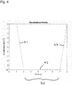
- the emergency braking distance 35 is predicted based on a deceleration profile for the target vehicle 13 as shown in Fig. 4 which describes the course of the acceleration during emergency braking.
- the acceleration in m/s 2 is shown on the y-axis over time in s on the x-axis.
- the acceleration includes zero or negative values only in order to describe the deceleration of the target vehicle 13 during emergency braking.
- a constant increase 41 of the deceleration (negative acceleration) is assumed up to a value of approximately -10 m/s 2 .
- the constant increase 41 of the deceleration corresponds to a constant jerk j start of the target vehicle 13 at the beginning of the emergency braking.
- a constant maximum deceleration 43 is assumed for a predetermined time period 45.
- the predetermined time period is about 5 seconds, i.e. from the instant of time at 2 seconds up to the instant of time at 7 seconds.
- a constant decrease 47 of a deceleration from -10 m/s 2 to approximately zero is assumed.
- the constant decrease of deceleration corresponds again to a constant jerk j end of the target vehicle 13 at the end of the emergency braking.
- d j start v in t react + t j start + j start t j start 3 6 t react and t j start are the reaction time and the elapsed time during the beginning of the emergency braking, respectively, wherein each is e.g. 1 second in the example of Fig. 4 , and j start is the constant jerk corresponding to the constant increase 41 of deceleration as shown in Fig. 4 .
- the second distance d a const is travelled by the target vehicle 13 during a "constant deceleration phase", i.e. during the predetermined time period 45 as shown in Fig. 4 in which the deceleration has the constant value 43.
- the third distance d j end is travelled by the target vehicle 13 during the end of emergency braking, wherein a constant jerk j end is assumed again corresponding to the constant decrease 47 of deceleration as shown in Fig. 4 .
- Fig. 5 depicts the movement of the target vehicle 13 as assumed during emergency steering in order to predict the emergency steering distance d ES , 51.
- the target vehicle 13 is at the observed position 31 corresponding again to the position of the target vehicle 13 as shown in Fig. 1 and as being detected by the detection system 17 of the host vehicle 11.
- the host vehicle 13 is at a position 53 within an adjacent lane 55, i.e. adjacent to the current lane 15 in which the host vehicle 11 and the target vehicle 13 are currently moving (see Fig. 1 ).
- a trajectory 57 is assumed for the movement of the target vehicle 13 wherein the trajectory 57 includes two curves having a certain constant absolute value for the radius of curvature R, but being opposite to each other regarding the sign.
- the two curves are connected smoothly such that the trajectory 57 has a unique tangent at a connection point 59 of the two curves.
- a constant longitudinal velocity v long is assumed which corresponds to the current velocity of the target vehicle 13 as detected by the detection system 17 of the host vehicle 11 and to the initial velocity v in as assumed at the beginning of the emergency braking (see Fig. 3 ).
- a predefined maximum lateral acceleration a lat max is assumed for the target vehicle 13. That is, for the change of the state of motion of the target vehicle 13 in lateral direction the "worst case" is assumed by taking into account the maximum lateral acceleration the target vehicle 13 can achieve.
- the emergency steering distance 51 is calculated from the starting position 31 of the target vehicle 13 up to the position 59 at which the target vehicle 13 will have moved half its width laterally when moving to the adjacent lane 55 during emergency steering.
- the distance 51 up to the position 59 can be considered as free from obstacles for the movement of the host vehicle 11 (see Fig. 1 ) although the movement of the target vehicle 13 is deteriorated by the emergency steering.
- a minimum extension distance 27 for the current obstacle free distance is estimated based on the emergency braking distance 35 and the emergency steering distance 51 being predicted as described above. Since emergency braking and emergency steering are "worst cases" for the change of the state of motion of the target vehicle 13, the safety for the host vehicle 11 regarding collision avoidance is ensured in spite of the extension 27 of the current obstacle free distance 24. Due to this extension 27, a higher availability for safety functions is provided for the host vehicle 11, including e.g. lane keeping assistance (LKA), lane change warning (LCW), side collision warning (SCW), and for comfort functions like lane centering (LC).
- LKA lane keeping assistance
- LCW lane change warning
- SCW side collision warning
Abstract
Description
- The present disclosure relates to a method and a system for determining a usable distance between a host vehicle and a moving object.
- Advanced driver assistance systems (ADAS) have been developed to support drivers in order to drive a host vehicle more safely and comfortably. These systems comprise, for example, active control of Electronic Power Assistance Steering (EPAS) like Lane Keeping Assistance (LKA), Lane Change Warning (LCW) and Side Collision Warning (SCW).
- Due to safety reasons, an obstacle free distance or space in a lane in front of the host vehicle needs to be above a certain predetermined limit. The free distance or space in front of the host vehicle is usually determined by visual and/or radar systems which are installed on the host vehicle.
- When determining the free distance or space, the shortest distance to an obstacle is usually detected without considering whether the obstacle or object in front of the vehicle is moving or stationary. For example, if the detected obstacle is a further vehicle moving in the same lane in front of the host vehicle with at least the same velocity, the actual safety distance required for the assistance systems to perform properly is longer than the predetermined safety distance considering stationary objects only. This is due to the fact that the further vehicle will not be at the detected position when the host vehicle will arrive there.
- As a consequence, the assistance systems will not be enabled (or will be deactivated if they were enabled before) if the detected obstacle free distance or space is smaller than the predetermined limit, although it is actually not required to set the assistance systems aside for safety reasons. Instead, the safety of the host vehicle could be improved in such a situation with respect to an environment comprising moving objects if the assistance systems mentioned above were activated. This holds true although the actual detected obstacle free distance might be somewhat below the predetermined safety distance taking into account stationary objects only. In other words, it may be more dangerous to leave these assistance systems in a deactivated state than having such systems activated in a surrounding in which moving objects slightly undershoot the predetermined safety distance.
- Accordingly, there is a need to provide a method and a system for determining an actually usable free distance with respect to a moving object in front of a host vehicle.
- The present disclosure provides a computer implemented method, a computer system and a non-transitory computer readable medium according to the independent claims. Embodiments are given in the subclaims, the description and the drawings.
- In one aspect, the present disclosure is directed at a computer implemented method for determining a usable distance between a host vehicle and a moving object. According to the method, a current obstacle free distance is detected in front of the host vehicle via a detection system of the host vehicle, wherein the current obstacle free distance is limited by a current position of the moving object, and a current velocity of the moving object is determined via the detection system. An extension distance is estimated based on the current velocity of the moving object via a prediction module of the host vehicle, and the usable distance is determined based on the current obstacle free distance and the extension distance via the prediction module.
- The usable distance may be regarded as an effective safety distance in order to decide whether assistance systems like lane keeping assistance (LKA), lane change warning (LCW) and side collision warning (SCW) are to be activated (or should remain activated). The current obstacle free distance which takes into account the "static situation" only at the current instant of time is prolonged by the extension distance which is based on the movement of the vehicle, i.e. based on its current velocity. For example, the usable distance may be the sum of the current obstacle free distance and the extension distance.
- Due to the prolongation of the current obstacle free distance by the extension distance, the assistance systems mentioned above will be available for supporting a driver of the host vehicle in situations in which these systems would not be available if the extension distance were not taken into account. Conversely, unnecessary cycles of deactivation and activation can be avoided for the assistance systems.
- Therefore, the safety of a driver and further occupants in the host vehicle is improved by increasing the availability of assistance systems in an environment comprising moving objects. However, the dependence of the extension distance on the current velocity of the moving object may be defined in such a manner that a certain safety margin is not exceeded which takes into account sudden changes of the movement (e.g. due to braking and/or steering) of the object under consideration.
- The method may comprise one or more of the following features:
The extension distance may be estimated by predicting an emergency braking distance and an emergency steering distance of the moving object, wherein the extension distance may be determined as a minimum of the predicted emergency braking distance and of the predicted emergency steering distance. - The emergency braking distance may be predicted based on a predefined constant deceleration being applied to the moving object for a predetermined time period, and further based on a predefined jerk being applied to the moving object before and after the predetermined time period, respectively, wherein the jerk is defined as a rate of change per time period of the deceleration of the moving object. The predefined jerk may have a respective constant absolute value before and after the predetermined time period, wherein the respective constant absolute values of the jerk before and after the predetermined time period may be equal.
- The emergency steering distance of the moving object may be predicted based on a predefined maximum lateral acceleration of the moving object, and it may be further predicted based on a predefined shape of a trajectory of the moving object during emergency braking. The trajectory may include two curves having a predefined radius of curvature being opposite to each other and being smoothly connected such that the trajectory may have a unique tangent at a connection point of the two curves. Furthermore, the emergency steering distance may be determined with respect to a predicted position of the moving object at which the moving object will have moved half its width laterally during emergency steering.
- According to an embodiment, the extension distance is estimated by predicting an emergency braking distance and an emergency steering distance of the moving object, wherein the extension distance may be determined as a minimum of the predicted emergency braking distance and the predicted emergency steering distance. Therefore, emergency braking and emergency steering may be taken into account when estimating the extension distance in order to consider the "worst case" for changing the movement of the object. In other words, the current obstacle free distance is prolonged by the extension distance in order to yield the usable distance without sacrificing the safety for the host vehicle since emergency braking and emergency steering of the object (e.g. a preceding vehicle) are taken into account for estimating and therefore restrict the extension distance. The extension distance is determined as a minimum of the two predicted distances since emergency braking and emergency steering need to be considered independently and it is not known in advance which of these will have the stronger effect.
- The emergency braking distance may be predicted based on a predefined constant deceleration which is applied to the moving object for a predetermined time period. Therefore, the emergency braking distance is predicted based on a straightforward model assuming a constant deceleration of the moving object. Hence, the prediction or estimation of the safety distances to ensure a proper performance of the assistance systems is facilitated. The predefined constant deceleration may be based on empirical values, e.g. being determined for the emergency braking behavior of known vehicles. In addition, the value for the constant deceleration may depend on the type and/or size of the moving object which is detected in front of the host vehicle. In this case, the constant deceleration may be selected from a group of predefined values including a respective value for each type and/or range for the size of the moving object.
- The emergency braking distance may further be predicted based on a predefined jerk being applied to the moving object before and after the predetermined time period, respectively, wherein the jerk is defined as a rate of change per time period of the deceleration of the moving object. The predefined jerk may be a respective constant absolute value before and after the predetermined time period, and these respective constant absolute values for the jerk may be equal.
- The predefined jerk may be adapted to the constant deceleration during the predetermined time period such that the jerks describe an increase of the deceleration before the predetermined time period and a decrease of deceleration after the predetermined time period. By using the predefined jerks the straightforward model for describing the emergency braking is refined, wherein predefining the jerk before and after the predetermined time period may also be based on empirical values. Hence, the execution of the method may again be facilitated by using a straightforward model for emergency braking including predefined values.
- The emergency steering distance of the moving object may be predicted based on a predefined maximum lateral acceleration of the moving object. That is, due to the emergency steering distance a sudden movement of the object in lateral direction is taken into account, i.e. in a direction perpendicular to the current moving direction of the host vehicle within a lane. The predefined maximum lateral acceleration may describe the "worst case" for the sudden movement of the object in the lateral direction. Therefore, the emergency steering distance may correspond to a safety margin for the extension distance when considering the lateral movement of the object.
- The emergency steering distance may further be predicted based on a predefined shape of a trajectory of the moving object during emergency braking. In detail, the trajectory may include two curves having a predefined radius of curvature being opposite to each other and being smoothly connected such that the trajectory has a unique tangent at a connection point of the two curves. Such a predefined shape for the trajectory of the moving object may be regarded as a straightforward model for the movement of the object which may facilitate the prediction and the estimation of the safety distances required for the assistance systems.
- The emergency steering distance may be determined with respect to a predicted position of the moving object at which the moving object will have moved half its width laterally during emergency steering. The predicted position of the laterally moving object during emergency steering may therefore define a safety margin again for estimating the extension distance, in this case regarding the lateral movement. It is assumed that the moving object will not be a risky obstacle after the host vehicle will have covered the current obstacle free distance plus the emergency steering distance determined based on the "half width" of the moving object performing emergency steering. Hence, the safety of the host vehicle will not be sacrificed in favor of extending the current obstacle free distance.
- In another aspect, the present disclosure is directed at a system for determining a usable distance between a host vehicle and a moving object, said system comprising a perception module and a prediction module. The perception module is configured to detect a current obstacle free distance in front of the host vehicle via a detection system of the host vehicle, wherein the current obstacle free distance is limited by a current position of the moving object, and to determine a current velocity of the moving object via the detection system. The prediction module is configured to predict an extension distance based on the current velocity of the moving object, and to determine the usable distance based on the current obstacle free distance and the extension distance.
- As used herein, the term module may refer to, be part of, or include an Application Specific Integrated Circuit (ASIC), an electronic circuit, a combinational logic circuit, a field programmable gate array (FPGA), a processor (shared, dedicated, or group) that executes code, other suitable components that provide the described functionality, or a combination of some or all of the above, such as in a system-on-chip. The term module may include memory (shared, dedicated, or group) that stores code executed by the processor.
- In summary, the system according to the disclosure comprises two modules for performing the steps as described above for the corresponding method. Therefore, the benefits and advantages as described above for the method are also valid for the system according to the disclosure.
- The detection system of the host vehicle may comprise a visual system and/or a RADAR system and/or a LIDAR system being configured to detect the current obstacle free distance, wherein the RADAR system and/or the LIDAR system may additionally be configured to determine the current velocity of the moving object.
- The visual system, the RADAR system and/or the LIDAR system may already be implemented in the host vehicle. Therefore, the current obstacle free distance and the current velocity of the moving object may already be available for other assistance systems. Hence, the system may be implemented at low cost, e.g. by generating suitable software for the perception module and for the prediction module.
- In another aspect, the present disclosure is directed at a computer system, said computer system being configured to carry out several or all steps of the computer implemented method described herein.
- The computer system may comprise a processing unit, at least one memory unit and at least one non-transitory data storage. The non-transitory data storage and/or the memory unit may comprise a computer program for instructing the computer to perform several or all steps or aspects of the computer implemented method described herein.
- In another aspect, the present disclosure is directed at a non-transitory computer readable medium comprising instructions for carrying out several or all steps or aspects of the computer implemented method described herein. The computer readable medium may be configured as: an optical medium, such as a compact disc (CD) or a digital versatile disk (DVD); a magnetic medium, such as a hard disk drive (HDD); a solid state drive (SSD); a read only memory (ROM), such as a flash memory; or the like. Furthermore, the computer readable medium may be configured as a data storage that is accessible via a data connection, such as an internet connection. The computer readable medium may, for example, be an online data repository or a cloud storage.
- The present disclosure is also directed at a computer program for instructing a computer to perform several or all steps or aspects of the computer implemented method described herein.
- Exemplary embodiments and functions of the present disclosure are described herein in conjunction with the following drawings, showing schematically:
- Fig. 1
- depicts a host vehicle, a target vehicle being detected as a moving object and the free space there between,
- Fig. 2
- depicts a schematic block diagram of a system for determining a usable distance between the host vehicle and the target vehicle,
- Fig. 3
- depicts an emergency braking maneuver of the target vehicle,
- Fig. 4
- depicts a braking profile for the emergency braking of the target vehicle, and
- Fig. 5
- depicts an emergency steering maneuver of the target vehicle.
-
Fig. 1 depicts ahost vehicle 11 driving behind atarget vehicle 13 in the samecurrent lane 15 of a road. Thehost vehicle 11 includes adetection system 17 for monitoring the environment of thehost vehicle 11. Thedetection system 17 may include a visual system and/or a radar system and/or a LIDAR system being implemented in thehost vehicle 11. - Via the
detection system 17, the existence and the current velocity of thetarget vehicle 13 are determined. Therefore, thetarget vehicle 13 may be regarded as a moving object in front of thehost vehicle 11. - The
detection system 17 of thehost vehicle 11 is further configured to determine an obstaclefree space 18 in front of thehost vehicle 11. The obstaclefree space 18 includes triangular shaped areas which are defined with respect to thehost vehicle 11 and obstacles being detected by thedetection system 17 in front of thehost vehicle 11. From the obstaclefree space 18, a minimum distance dFS with respect to the next obstacle is derived which may be regarded as current obstaclefree distance 24 for thehost vehicle 11. - According to the present disclosure, the
host vehicle 11 also includes a system 21 (seeFig. 2 ) configured to determine ausable distance 28 between thehost vehicle 11 and the target vehicle or movingobject 13. Thesystem 21 is able to additionally consider the movement of thetarget vehicle 13 when estimating a safety distance for thehost vehicle 11 which corresponds to theusable distance 28. Based on the movement of thetarget vehicle 13, thesystem 21 is configured to estimate an extension 19 (seeFig. 1 ) for the obstaclefree space 18 corresponding to an extension distance dext, 27 for the obstacle free distance dFS, 24. - The
usable distance 28 is therefore given as the sum of the current obstacle free distance dFS, 24 and the extension distance dext, 27. The usable distance may be also regarded as an effective safety distance for thehost vehicle 11 taking into account the movement of thetarget vehicle 13. For vehicles including conventional systems, the current obstacle free distance dFS, 24 is simply used as a safety distance for controlling advanced driver assistance systems (ADAS) including lane keeping assistance (LKA), lane change warning (LCW) and side collision warning (SCW). These systems are usually deactivated if the current obstacle free distance dFS, 24 falls below a certain predefined limit. In other words, conventional systems do not consider the movement of thetarget vehicle 13 for the decision whether to deactivate the above-mentioned driver assistance systems. - Due to the movement of the
target vehicle 13, however, the driver assistance systems could still be activated in many situations although the obstacle free distance is already below the predefined value or "static safety distance". According to the present disclosure, the current obstacle free distance dFS is therefore extended by taking the movement of thetarget vehicle 13 into account without sacrificing the safety requirements for thehost vehicle 11. -
Fig. 2 depicts a schematic diagram of thesystem 21 for determining theusable distance 28 between thehost vehicle 11 and the target vehicle 13 (seeFig. 1 ) as a moving object in front of thehost vehicle 11. Thesystem 21 includes aperception module 23 and aprediction module 25. Theperception module 23 is configured to detect the current obstacle free distance dFS, 24 in front of thehost vehicle 11. Theperception module 23 is further configured to determine acurrent velocity 26 of the moving object ortarget vehicle 13. The obstaclefree distance 24 and thecurrent velocity 26 of thetarget vehicle 13 are determined based on output data provided by the detection system 17 (seeFig. 1 ) of thehost vehicle 11. - The
prediction module 25 receives the current obstaclefree distance 24 and the current velocity of thetarget vehicle 13 from theperception module 23 and is configured to estimate theextension distance 27 based on thecurrent velocity 26 of the moving object ortarget vehicle 13. The estimation of theextension distance 27 will be described in context ofFigs. 3 ,4 and5 below. Theprediction module 25 is further configured to determine theusable distance 28 based on the current obstaclefree distance 24 and theextension distance 27. Theusable distance 28 is depicted inFig. 2 as output of theprediction module 25. Theusable distance 28 is determined as the sum of the current obstaclefree distance 24 and theextension distance 27. As mentioned above, thehost vehicle 11 further includes advanced driver assistance systems (ADAS) which are depicted as 29 inFig. 2 . Theusable distance 28 is provided by theprediction module 25 for the advanceddriver assistance systems 29 in order to decide based on theusable distance 28 whether certain assistance systems like lane keeping assistance (LKA), lane change warning (LCW) and side collision warning (SCW) are to be activated or deactivated. - In order to estimate the extension distance 27 (see
Fig. 1 ) two types of changes are taken into account for the state of motion of the target vehicle or moving object 13: i) emergency braking, i.e. a change of the state of motion of thetarget vehicle 13 in longitudinal direction along thecurrent line 15 up to a velocity of almost zero of the target vehicle 13 (seeFig. 3 ), and ii) emergency steering, i.e. a change of the state of motion of thetarget vehicle 13 in lateral direction, e.g. in order to avoid a collision with an obstacle in front of the target vehicle 13 (seeFig. 5 ). Emergency braking and emergency steering may be regarded as "worst cases" for a change of the state of motion of thetarget vehicle 13, rendering the longest extension distance which still ensures safety for thehost vehicle 11. Therefore, the extension distance is estimated as a minimum of an emergency braking distance 35 (seeFig. 3 ) and an emergency steering distance 51 (seeFig. 5 ) of the moving object ortarget vehicle 13 which are each predicted based on a model for the emergency braking and the emergency steering of thetarget vehicle 13, as will be described in context ofFig. 3 andFig. 5 , respectively. -
Fig. 3 depicts a situation in which thetarget vehicle 13 performs emergency braking. At the beginning, thetarget vehicle 13 is at an observedposition 31 which corresponds to the position as shown inFig. 1 in front of thehost vehicle 11. That is, thetarget vehicle 13 is detected by thehost vehicle 11 at theposition 31 and has avelocity 26 which is also detected by thehost vehicle 11 via thedetection system 17. In order to predict the emergency braking distance dEB, 35, it is assumed that thetarget vehicle 13 is at aposition 33 after emergency braking and has a velocity of approximately zero. - In detail, the
emergency braking distance 35 is predicted based on a deceleration profile for thetarget vehicle 13 as shown inFig. 4 which describes the course of the acceleration during emergency braking. InFig. 4 , the acceleration in m/s2 is shown on the y-axis over time in s on the x-axis. The acceleration includes zero or negative values only in order to describe the deceleration of thetarget vehicle 13 during emergency braking. - At the beginning, e.g. during a reaction time of the driver of the
target vehicle 13 of approximately one second, the acceleration is still zero, and thereafter aconstant increase 41 of the deceleration (negative acceleration) is assumed up to a value of approximately -10 m/s2. Theconstant increase 41 of the deceleration corresponds to a constant jerk jstart of thetarget vehicle 13 at the beginning of the emergency braking. After reaching the maximum deceleration of -10 m/s2, a constantmaximum deceleration 43 is assumed for apredetermined time period 45. In the example ofFig. 4 , the predetermined time period is about 5 seconds, i.e. from the instant of time at 2 seconds up to the instant of time at 7 seconds. Thereafter, i.e. at 7 seconds, aconstant decrease 47 of a deceleration from -10 m/s2 to approximately zero is assumed. The constant decrease of deceleration corresponds again to a constant jerk jend of thetarget vehicle 13 at the end of the emergency braking. - Based on the deceleration profile as shown in
Fig. 4 , the emergency braking distance dEB, 35 is calculated as a sum of three partial distances as follows:
start is the distance which the target vehicle or movingobject 13 travels at the beginning of the emergency braking, i.e. during the reaction time and during theconstant increase 41 of the deceleration corresponding to the constant jerk of thetarget vehicle 13. If an initial velocity vin of thetarget vehicle 13 is given, i.e. as detected by thedetection system 17 of thehost vehicle 11, the distance travelled by thehost vehicle 13 during the beginning of the emergency braking is calculated as follows:
start are the reaction time and the elapsed time during the beginning of the emergency braking, respectively, wherein each is e.g. 1 second in the example ofFig. 4 , and jstart is the constant jerk corresponding to theconstant increase 41 of deceleration as shown inFig. 4 . - The second distance da
const is travelled by thetarget vehicle 13 during a "constant deceleration phase", i.e. during thepredetermined time period 45 as shown inFig. 4 in which the deceleration has theconstant value 43. The second distance is calculated as follows:
const is thepredetermined time period 45 for the constant deceleration phase, and aavg is theconstant deceleration 43 during this time period 45 (seeFig. 4 ). - The third distance dj
end is travelled by thetarget vehicle 13 during the end of emergency braking, wherein a constant jerk jend is assumed again corresponding to theconstant decrease 47 of deceleration as shown inFig. 4 . The third distance is calculated as follows:
end is the elapsed time during theconstant decrease 47 of the deceleration and jend is the constant jerk corresponding to thisconstant decrease 47 of deceleration. -
Fig. 5 depicts the movement of thetarget vehicle 13 as assumed during emergency steering in order to predict the emergency steering distance dES, 51. At the beginning of the emergency steering, thetarget vehicle 13 is at the observedposition 31 corresponding again to the position of thetarget vehicle 13 as shown inFig. 1 and as being detected by thedetection system 17 of thehost vehicle 11. At the end of the emergency steering, thehost vehicle 13 is at aposition 53 within anadjacent lane 55, i.e. adjacent to thecurrent lane 15 in which thehost vehicle 11 and thetarget vehicle 13 are currently moving (seeFig. 1 ). - In order to describe the emergency steering, a
trajectory 57 is assumed for the movement of thetarget vehicle 13 wherein thetrajectory 57 includes two curves having a certain constant absolute value for the radius of curvature R, but being opposite to each other regarding the sign. The two curves are connected smoothly such that thetrajectory 57 has a unique tangent at aconnection point 59 of the two curves. - For the movement of the
target vehicle 13, a constant longitudinal velocity vlong is assumed which corresponds to the current velocity of thetarget vehicle 13 as detected by thedetection system 17 of thehost vehicle 11 and to the initial velocity vin as assumed at the beginning of the emergency braking (seeFig. 3 ). Furthermore, a predefined maximum lateral acceleration alatmax is assumed for thetarget vehicle 13. That is, for the change of the state of motion of thetarget vehicle 13 in lateral direction the "worst case" is assumed by taking into account the maximum lateral acceleration thetarget vehicle 13 can achieve. Under these assumptions, the radius of curvature R for the two curves forming the trajectory 57 (seeFig. 5 ) is calculated as follows:
- The
emergency steering distance 51 is calculated from the startingposition 31 of thetarget vehicle 13 up to theposition 59 at which thetarget vehicle 13 will have moved half its width laterally when moving to theadjacent lane 55 during emergency steering. Thedistance 51 up to theposition 59 can be considered as free from obstacles for the movement of the host vehicle 11 (seeFig. 1 ) although the movement of thetarget vehicle 13 is deteriorated by the emergency steering. - In summary, by considering the possibility of emergency braking and emergency steering for the movement of the
target vehicle 13, aminimum extension distance 27 for the current obstacle free distance is estimated based on theemergency braking distance 35 and theemergency steering distance 51 being predicted as described above. Since emergency braking and emergency steering are "worst cases" for the change of the state of motion of thetarget vehicle 13, the safety for thehost vehicle 11 regarding collision avoidance is ensured in spite of theextension 27 of the current obstaclefree distance 24. Due to thisextension 27, a higher availability for safety functions is provided for thehost vehicle 11, including e.g. lane keeping assistance (LKA), lane change warning (LCW), side collision warning (SCW), and for comfort functions like lane centering (LC). -
- 11
- host vehicle
- 13
- target vehicle
- 15
- current lane
- 17
- detection system
- 18
- obstacle free space
- 19
- extension of obstacle free space
- 21
- system
- 23
- perception module
- 24
- current obstacle free distance
- 25
- prediction module
- 26
- current velocity of moving object (target vehicle)
- 27
- extension distance
- 28
- usable distance
- 29
- advanced driver assistance systems
- 31
- observed position of moving object (target vehicle)
- 33
- position of moving object (target vehicle) after emergency braking
- 35
- emergency braking distance
- 41
- constant increase of deceleration
- 43
- constant deceleration
- 45
- predetermined time period
- 47
- constant decrease of deceleration
- 51
- emergency steering distance
- 53
- position of moving object (target vehicle) after emergency steering
- 55
- adjacent lane
- 57
- trajectory of target vehicle
- 59
- position during emergency steering
Claims (15)
- Computer implemented method for determining a usable distance (28) between a host vehicle (11) and a moving object (13),
the method comprising:- detecting a current obstacle free distance (24) in front of the host vehicle (11) via a detection system (17) of the host vehicle (11), wherein the current obstacle free distance (24) is limited by a current position (31) of the moving object (13),- determining a current velocity (26) of the moving object (13) via the detection system (17),- estimating an extension distance (27) based on the current velocity (26) of the moving object (13) via a prediction module (25) of the host vehicle (11), and- determining, via the prediction module (25), the usable distance (28) based on the current obstacle free distance (24) and the extension distance (27). - Method according to claim 1, wherein
the extension distance (27) is estimated by predicting an emergency braking distance (35) and an emergency steering distance (51) of the moving object (13). - Method according to claim 2, wherein
the extension distance (27) is determined as a minimum of the predicted emergency braking distance (35) and of the predicted emergency steering distance (51). - Method according to claim 2 or 3, wherein
the emergency braking distance (35) is predicted based on a predefined constant deceleration (43) being applied to the moving object (13) for a predetermined time period (45). - Method according to claim 4, wherein
the emergency braking distance (35) is further predicted based on a predefined jerk (41, 47) being applied to the moving object (13) before and after the predetermined time period (45), respectively, the jerk (41, 47) being defined as a rate of change per time period of the deceleration of the moving object (13). - Method according to claim 5, wherein
the predefined jerk (41, 47) has a respective constant absolute value before and after the predetermined time period (45). - Method according to claim 6, wherein
the respective constant absolute values of the jerk (41, 47) before and after the predetermined time period (45) are equal. - Method according to anyone of claims 2 to 7, wherein
the emergency steering distance (51) of the moving object (13) is predicted based on a predefined maximum lateral acceleration of the moving object (13). - Method according to claim 8, wherein
the emergency steering distance (51) is further predicted based on a predefined shape of a trajectory (57) of the moving object (13) during emergency braking. - Method according to claim 9, wherein
the trajectory (57) comprises two curves having a predefined radius of curvature being opposite to each other and being smoothly connected such that the trajectory (57) has a unique tangent at a connection point of the two curves. - Method according to anyone of claims 2 to 10, wherein
the emergency steering distance (51) is determined with respect to a predicted position (59) of the moving object (13) at which the moving object (13) will have moved half its width laterally during emergency steering. - System (21) for determining a usable distance (28) between a host vehicle (11) and a moving object (13),
the system comprising:- a perception module (23) configured to:detect a current obstacle free distance (24) in front of the host vehicle (11) via a detection system (17) of the host vehicle (11), wherein the current obstacle free distance (24) is limited by a current position of the moving object (13), anddetermine a current velocity (26) of the moving object (13) via the detection system (17), and- a prediction module (25) configured to:predict an extension distance (27) based on the current velocity (26) of the moving object (13), anddetermine the usable distance (28) based on the current obstacle free distance (24) and the extension distance (27). - System according to claim 12, wherein
the detection system (17) of the host vehicle (11) comprises a visual system and/or a RADAR system and/or a LIDAR system being configured to detect the current obstacle free distance (24), the RADAR system and/or the LIDAR system being additionally configured to determine the current velocity (26) of the moving object (13). - Computer system, the computer system being configured to carry out the computer implemented method of at least one of claims 1 to 11.
- Non-transitory computer readable medium comprising instructions for carrying out the computer implemented method of at least one of claims 1 to 11.
Priority Applications (3)
| Application Number | Priority Date | Filing Date | Title |
|---|---|---|---|
| EP20166617.9A EP3888988A1 (en) | 2020-03-30 | 2020-03-30 | Method and system for determining a usable distance in front of a vehicle |
| US17/195,536 US20210300353A1 (en) | 2020-03-30 | 2021-03-08 | Method and System for Determining a Usable Distance in Front of a Vehicle |
| CN202110332434.1A CN113460043B (en) | 2020-03-30 | 2021-03-29 | Method and system for determining available distance in front of vehicle |
Applications Claiming Priority (1)
| Application Number | Priority Date | Filing Date | Title |
|---|---|---|---|
| EP20166617.9A EP3888988A1 (en) | 2020-03-30 | 2020-03-30 | Method and system for determining a usable distance in front of a vehicle |
Publications (1)
| Publication Number | Publication Date |
|---|---|
| EP3888988A1 true EP3888988A1 (en) | 2021-10-06 |
Family
ID=70058166
Family Applications (1)
| Application Number | Title | Priority Date | Filing Date |
|---|---|---|---|
| EP20166617.9A Pending EP3888988A1 (en) | 2020-03-30 | 2020-03-30 | Method and system for determining a usable distance in front of a vehicle |
Country Status (2)
| Country | Link |
|---|---|
| US (1) | US20210300353A1 (en) |
| EP (1) | EP3888988A1 (en) |
Families Citing this family (3)
| Publication number | Priority date | Publication date | Assignee | Title |
|---|---|---|---|---|
| EP3882813A1 (en) | 2020-03-20 | 2021-09-22 | Aptiv Technologies Limited | Method for generating a dynamic occupancy grid |
| EP3905106A1 (en) | 2020-04-27 | 2021-11-03 | Aptiv Technologies Limited | Method for determining a drivable area |
| EP3905105A1 (en) | 2020-04-27 | 2021-11-03 | Aptiv Technologies Limited | Method for determining a collision free space |
Citations (3)
| Publication number | Priority date | Publication date | Assignee | Title |
|---|---|---|---|---|
| DE102009022588A1 (en) * | 2009-05-26 | 2010-12-02 | GM Global Technology Operations, Inc., Detroit | Vehicle i.e. lorry, surrounding area monitoring method, involves detecting leading vehicle as reference object and target object, and assigning relevance value to target object, where relevance value depends on leading vehicle |
| US20150012204A1 (en) * | 2012-02-14 | 2015-01-08 | Wabco Gmbh | Method for Determining an Emergency Braking Situation of a Vehicle |
| DE102016007630A1 (en) * | 2016-06-23 | 2017-12-28 | Wabco Gmbh | Method for determining an emergency braking situation of a vehicle and device for carrying out the method |
Family Cites Families (7)
| Publication number | Priority date | Publication date | Assignee | Title |
|---|---|---|---|---|
| US7124027B1 (en) * | 2002-07-11 | 2006-10-17 | Yazaki North America, Inc. | Vehicular collision avoidance system |
| JP2009120116A (en) * | 2007-11-16 | 2009-06-04 | Hitachi Ltd | Vehicle collision avoidance support device |
| US20120109421A1 (en) * | 2010-11-03 | 2012-05-03 | Kenneth Scarola | Traffic congestion reduction system |
| DE102013001228A1 (en) * | 2013-01-25 | 2014-07-31 | Wabco Gmbh | A method for determining a triggering criterion for a braking and emergency braking system for a vehicle |
| US10642275B2 (en) * | 2018-06-18 | 2020-05-05 | Zoox, Inc. | Occulsion aware planning and control |
| DE102019107412B3 (en) * | 2019-03-22 | 2020-07-09 | Zf Active Safety Gmbh | Control system and control method for driving a motor vehicle |
| US20210188286A1 (en) * | 2019-12-20 | 2021-06-24 | Baidu Usa Llc | A spline curve and spiral curve based reference line smoothing method |
-
2020
- 2020-03-30 EP EP20166617.9A patent/EP3888988A1/en active Pending
-
2021
- 2021-03-08 US US17/195,536 patent/US20210300353A1/en active Pending
Patent Citations (3)
| Publication number | Priority date | Publication date | Assignee | Title |
|---|---|---|---|---|
| DE102009022588A1 (en) * | 2009-05-26 | 2010-12-02 | GM Global Technology Operations, Inc., Detroit | Vehicle i.e. lorry, surrounding area monitoring method, involves detecting leading vehicle as reference object and target object, and assigning relevance value to target object, where relevance value depends on leading vehicle |
| US20150012204A1 (en) * | 2012-02-14 | 2015-01-08 | Wabco Gmbh | Method for Determining an Emergency Braking Situation of a Vehicle |
| DE102016007630A1 (en) * | 2016-06-23 | 2017-12-28 | Wabco Gmbh | Method for determining an emergency braking situation of a vehicle and device for carrying out the method |
Also Published As
| Publication number | Publication date |
|---|---|
| CN113460043A (en) | 2021-10-01 |
| US20210300353A1 (en) | 2021-09-30 |
Similar Documents
| Publication | Publication Date | Title |
|---|---|---|
| US20210300353A1 (en) | Method and System for Determining a Usable Distance in Front of a Vehicle | |
| CN108216220B (en) | Apparatus and method for boundary-based vehicle collision control | |
| US10788842B2 (en) | Apparatus and method for controlling platooning in leading vehicle | |
| US8849515B2 (en) | Steering assist in driver initiated collision avoidance maneuver | |
| US9272710B2 (en) | Apparatus and method for preventing vehicle collision | |
| EP2840007B1 (en) | Consistent behaviour generation of a predictive advanced driver assistant system | |
| WO2018211802A1 (en) | Autonomous driving assist device and autonomous driving assist method | |
| CN110435654B (en) | Car following method, device and equipment for intelligent navigation system | |
| WO2021103510A1 (en) | Method, device and storage medium for controlling autonomous vehicle | |
| JP5974607B2 (en) | Vehicle travel control device | |
| KR20150034400A (en) | Apparatus and method for controlling lane keeping | |
| US11332157B2 (en) | Vehicle control apparatus | |
| EP3885226A1 (en) | Method and system for planning the motion of a vehicle | |
| JP5507433B2 (en) | Driving assistance device | |
| JP2021026720A5 (en) | ||
| CN110908379A (en) | Vehicle track prediction method and device based on historical information and storage medium | |
| US20230054263A1 (en) | Obstacle avoidance control method and device, advanced driver-assistance system, vehicle, and medium | |
| CN114179795B (en) | System for predicting collision risk in lane change and method thereof | |
| JP6689337B2 (en) | Automatic operation control device and automatic operation control method | |
| JP2010095078A (en) | Route prediction device | |
| CN113460043B (en) | Method and system for determining available distance in front of vehicle | |
| KR20210065409A (en) | Method and Apparatus for Collision Avoidance Trajectory Planning of Autonomous Vehicle | |
| CN114735029A (en) | Control method and device for automatic driving vehicle | |
| CN115465283A (en) | Adaptive trust calibration | |
| CN114802251A (en) | Control method and device for automatic driving vehicle, electronic device and storage medium |
Legal Events
| Date | Code | Title | Description |
|---|---|---|---|
| PUAI | Public reference made under article 153(3) epc to a published international application that has entered the european phase |
Free format text: ORIGINAL CODE: 0009012 |
|
| STAA | Information on the status of an ep patent application or granted ep patent |
Free format text: STATUS: THE APPLICATION HAS BEEN PUBLISHED |
|
| AK | Designated contracting states |
Kind code of ref document: A1 Designated state(s): AL AT BE BG CH CY CZ DE DK EE ES FI FR GB GR HR HU IE IS IT LI LT LU LV MC MK MT NL NO PL PT RO RS SE SI SK SM TR |
|
| STAA | Information on the status of an ep patent application or granted ep patent |
Free format text: STATUS: REQUEST FOR EXAMINATION WAS MADE |
|
| 17P | Request for examination filed |
Effective date: 20220325 |
|
| RBV | Designated contracting states (corrected) |
Designated state(s): AL AT BE BG CH CY CZ DE DK EE ES FI FR GB GR HR HU IE IS IT LI LT LU LV MC MK MT NL NO PL PT RO RS SE SI SK SM TR |
|
| RAP3 | Party data changed (applicant data changed or rights of an application transferred) |
Owner name: APTIV TECHNOLOGIES LIMITED |
|
| GRAP | Despatch of communication of intention to grant a patent |
Free format text: ORIGINAL CODE: EPIDOSNIGR1 |
|
| STAA | Information on the status of an ep patent application or granted ep patent |
Free format text: STATUS: GRANT OF PATENT IS INTENDED |