EP3888956A1 - Independent vehicle suspension - Google Patents
Independent vehicle suspension Download PDFInfo
- Publication number
- EP3888956A1 EP3888956A1 EP21165122.9A EP21165122A EP3888956A1 EP 3888956 A1 EP3888956 A1 EP 3888956A1 EP 21165122 A EP21165122 A EP 21165122A EP 3888956 A1 EP3888956 A1 EP 3888956A1
- Authority
- EP
- European Patent Office
- Prior art keywords
- hub
- independent suspension
- vehicle
- electric motor
- axis
- Prior art date
- Legal status (The legal status is an assumption and is not a legal conclusion. Google has not performed a legal analysis and makes no representation as to the accuracy of the status listed.)
- Granted
Links
Images


Classifications
-
- B—PERFORMING OPERATIONS; TRANSPORTING
- B60—VEHICLES IN GENERAL
- B60G—VEHICLE SUSPENSION ARRANGEMENTS
- B60G3/00—Resilient suspensions for a single wheel
- B60G3/18—Resilient suspensions for a single wheel with two or more pivoted arms, e.g. parallelogram
- B60G3/20—Resilient suspensions for a single wheel with two or more pivoted arms, e.g. parallelogram all arms being rigid
-
- B—PERFORMING OPERATIONS; TRANSPORTING
- B60—VEHICLES IN GENERAL
- B60G—VEHICLE SUSPENSION ARRANGEMENTS
- B60G17/00—Resilient suspensions having means for adjusting the spring or vibration-damper characteristics, for regulating the distance between a supporting surface and a sprung part of vehicle or for locking suspension during use to meet varying vehicular or surface conditions, e.g. due to speed or load
- B60G17/015—Resilient suspensions having means for adjusting the spring or vibration-damper characteristics, for regulating the distance between a supporting surface and a sprung part of vehicle or for locking suspension during use to meet varying vehicular or surface conditions, e.g. due to speed or load the regulating means comprising electric or electronic elements
- B60G17/0152—Resilient suspensions having means for adjusting the spring or vibration-damper characteristics, for regulating the distance between a supporting surface and a sprung part of vehicle or for locking suspension during use to meet varying vehicular or surface conditions, e.g. due to speed or load the regulating means comprising electric or electronic elements characterised by the action on a particular type of suspension unit
- B60G17/0157—Resilient suspensions having means for adjusting the spring or vibration-damper characteristics, for regulating the distance between a supporting surface and a sprung part of vehicle or for locking suspension during use to meet varying vehicular or surface conditions, e.g. due to speed or load the regulating means comprising electric or electronic elements characterised by the action on a particular type of suspension unit non-fluid unit, e.g. electric motor
-
- B—PERFORMING OPERATIONS; TRANSPORTING
- B60—VEHICLES IN GENERAL
- B60K—ARRANGEMENT OR MOUNTING OF PROPULSION UNITS OR OF TRANSMISSIONS IN VEHICLES; ARRANGEMENT OR MOUNTING OF PLURAL DIVERSE PRIME-MOVERS IN VEHICLES; AUXILIARY DRIVES FOR VEHICLES; INSTRUMENTATION OR DASHBOARDS FOR VEHICLES; ARRANGEMENTS IN CONNECTION WITH COOLING, AIR INTAKE, GAS EXHAUST OR FUEL SUPPLY OF PROPULSION UNITS IN VEHICLES
- B60K7/00—Disposition of motor in, or adjacent to, traction wheel
- B60K7/0007—Disposition of motor in, or adjacent to, traction wheel the motor being electric
-
- B—PERFORMING OPERATIONS; TRANSPORTING
- B60—VEHICLES IN GENERAL
- B60G—VEHICLE SUSPENSION ARRANGEMENTS
- B60G11/00—Resilient suspensions characterised by arrangement, location or kind of springs
- B60G11/32—Resilient suspensions characterised by arrangement, location or kind of springs having springs of different kinds
-
- B—PERFORMING OPERATIONS; TRANSPORTING
- B60—VEHICLES IN GENERAL
- B60G—VEHICLE SUSPENSION ARRANGEMENTS
- B60G7/00—Pivoted suspension arms; Accessories thereof
- B60G7/006—Attaching arms to sprung or unsprung part of vehicle, characterised by comprising attachment means controlled by an external actuator, e.g. a fluid or electrical motor
-
- B—PERFORMING OPERATIONS; TRANSPORTING
- B60—VEHICLES IN GENERAL
- B60J—WINDOWS, WINDSCREENS, NON-FIXED ROOFS, DOORS, OR SIMILAR DEVICES FOR VEHICLES; REMOVABLE EXTERNAL PROTECTIVE COVERINGS SPECIALLY ADAPTED FOR VEHICLES
- B60J5/00—Doors
- B60J5/10—Doors arranged at the vehicle rear
- B60J5/108—Doors arranged at the vehicle rear for load transporting vehicles or public transport, e.g. lorries, trucks, buses
-
- B—PERFORMING OPERATIONS; TRANSPORTING
- B60—VEHICLES IN GENERAL
- B60K—ARRANGEMENT OR MOUNTING OF PROPULSION UNITS OR OF TRANSMISSIONS IN VEHICLES; ARRANGEMENT OR MOUNTING OF PLURAL DIVERSE PRIME-MOVERS IN VEHICLES; AUXILIARY DRIVES FOR VEHICLES; INSTRUMENTATION OR DASHBOARDS FOR VEHICLES; ARRANGEMENTS IN CONNECTION WITH COOLING, AIR INTAKE, GAS EXHAUST OR FUEL SUPPLY OF PROPULSION UNITS IN VEHICLES
- B60K17/00—Arrangement or mounting of transmissions in vehicles
- B60K17/04—Arrangement or mounting of transmissions in vehicles characterised by arrangement, location or kind of gearing
- B60K17/043—Transmission unit disposed in on near the vehicle wheel, or between the differential gear unit and the wheel
-
- B—PERFORMING OPERATIONS; TRANSPORTING
- B60—VEHICLES IN GENERAL
- B60K—ARRANGEMENT OR MOUNTING OF PROPULSION UNITS OR OF TRANSMISSIONS IN VEHICLES; ARRANGEMENT OR MOUNTING OF PLURAL DIVERSE PRIME-MOVERS IN VEHICLES; AUXILIARY DRIVES FOR VEHICLES; INSTRUMENTATION OR DASHBOARDS FOR VEHICLES; ARRANGEMENTS IN CONNECTION WITH COOLING, AIR INTAKE, GAS EXHAUST OR FUEL SUPPLY OF PROPULSION UNITS IN VEHICLES
- B60K17/00—Arrangement or mounting of transmissions in vehicles
- B60K17/04—Arrangement or mounting of transmissions in vehicles characterised by arrangement, location or kind of gearing
- B60K17/043—Transmission unit disposed in on near the vehicle wheel, or between the differential gear unit and the wheel
- B60K17/046—Transmission unit disposed in on near the vehicle wheel, or between the differential gear unit and the wheel with planetary gearing having orbital motion
-
- B—PERFORMING OPERATIONS; TRANSPORTING
- B60—VEHICLES IN GENERAL
- B60K—ARRANGEMENT OR MOUNTING OF PROPULSION UNITS OR OF TRANSMISSIONS IN VEHICLES; ARRANGEMENT OR MOUNTING OF PLURAL DIVERSE PRIME-MOVERS IN VEHICLES; AUXILIARY DRIVES FOR VEHICLES; INSTRUMENTATION OR DASHBOARDS FOR VEHICLES; ARRANGEMENTS IN CONNECTION WITH COOLING, AIR INTAKE, GAS EXHAUST OR FUEL SUPPLY OF PROPULSION UNITS IN VEHICLES
- B60K17/00—Arrangement or mounting of transmissions in vehicles
- B60K17/04—Arrangement or mounting of transmissions in vehicles characterised by arrangement, location or kind of gearing
- B60K17/06—Arrangement or mounting of transmissions in vehicles characterised by arrangement, location or kind of gearing of change-speed gearing
- B60K17/08—Arrangement or mounting of transmissions in vehicles characterised by arrangement, location or kind of gearing of change-speed gearing of mechanical type
-
- B—PERFORMING OPERATIONS; TRANSPORTING
- B60—VEHICLES IN GENERAL
- B60K—ARRANGEMENT OR MOUNTING OF PROPULSION UNITS OR OF TRANSMISSIONS IN VEHICLES; ARRANGEMENT OR MOUNTING OF PLURAL DIVERSE PRIME-MOVERS IN VEHICLES; AUXILIARY DRIVES FOR VEHICLES; INSTRUMENTATION OR DASHBOARDS FOR VEHICLES; ARRANGEMENTS IN CONNECTION WITH COOLING, AIR INTAKE, GAS EXHAUST OR FUEL SUPPLY OF PROPULSION UNITS IN VEHICLES
- B60K7/00—Disposition of motor in, or adjacent to, traction wheel
-
- B—PERFORMING OPERATIONS; TRANSPORTING
- B62—LAND VEHICLES FOR TRAVELLING OTHERWISE THAN ON RAILS
- B62D—MOTOR VEHICLES; TRAILERS
- B62D7/00—Steering linkage; Stub axles or their mountings
- B62D7/18—Steering knuckles; King pins
-
- B—PERFORMING OPERATIONS; TRANSPORTING
- B60—VEHICLES IN GENERAL
- B60G—VEHICLE SUSPENSION ARRANGEMENTS
- B60G2200/00—Indexing codes relating to suspension types
- B60G2200/10—Independent suspensions
-
- B—PERFORMING OPERATIONS; TRANSPORTING
- B60—VEHICLES IN GENERAL
- B60G—VEHICLE SUSPENSION ARRANGEMENTS
- B60G2200/00—Indexing codes relating to suspension types
- B60G2200/10—Independent suspensions
- B60G2200/14—Independent suspensions with lateral arms
- B60G2200/144—Independent suspensions with lateral arms with two lateral arms forming a parallelogram
-
- B—PERFORMING OPERATIONS; TRANSPORTING
- B60—VEHICLES IN GENERAL
- B60G—VEHICLE SUSPENSION ARRANGEMENTS
- B60G2202/00—Indexing codes relating to the type of spring, damper or actuator
- B60G2202/10—Type of spring
- B60G2202/15—Fluid spring
- B60G2202/152—Pneumatic spring
-
- B—PERFORMING OPERATIONS; TRANSPORTING
- B60—VEHICLES IN GENERAL
- B60G—VEHICLE SUSPENSION ARRANGEMENTS
- B60G2204/00—Indexing codes related to suspensions per se or to auxiliary parts
- B60G2204/10—Mounting of suspension elements
- B60G2204/18—Mounting of vehicle engines
- B60G2204/182—Electric motor on wheel support
-
- B—PERFORMING OPERATIONS; TRANSPORTING
- B60—VEHICLES IN GENERAL
- B60G—VEHICLE SUSPENSION ARRANGEMENTS
- B60G2204/00—Indexing codes related to suspensions per se or to auxiliary parts
- B60G2204/40—Auxiliary suspension parts; Adjustment of suspensions
- B60G2204/419—Gears
- B60G2204/4191—Planetary or epicyclic gears
-
- B—PERFORMING OPERATIONS; TRANSPORTING
- B60—VEHICLES IN GENERAL
- B60G—VEHICLE SUSPENSION ARRANGEMENTS
- B60G2206/00—Indexing codes related to the manufacturing of suspensions: constructional features, the materials used, procedures or tools
- B60G2206/01—Constructional features of suspension elements, e.g. arms, dampers, springs
- B60G2206/50—Constructional features of wheel supports or knuckles, e.g. steering knuckles, spindle attachments
-
- B—PERFORMING OPERATIONS; TRANSPORTING
- B60—VEHICLES IN GENERAL
- B60G—VEHICLE SUSPENSION ARRANGEMENTS
- B60G2300/00—Indexing codes relating to the type of vehicle
- B60G2300/02—Trucks; Load vehicles
-
- B—PERFORMING OPERATIONS; TRANSPORTING
- B60—VEHICLES IN GENERAL
- B60G—VEHICLE SUSPENSION ARRANGEMENTS
- B60G2300/00—Indexing codes relating to the type of vehicle
- B60G2300/14—Buses
-
- B—PERFORMING OPERATIONS; TRANSPORTING
- B60—VEHICLES IN GENERAL
- B60G—VEHICLE SUSPENSION ARRANGEMENTS
- B60G2300/00—Indexing codes relating to the type of vehicle
- B60G2300/50—Electric vehicles; Hybrid vehicles
-
- B—PERFORMING OPERATIONS; TRANSPORTING
- B60—VEHICLES IN GENERAL
- B60G—VEHICLE SUSPENSION ARRANGEMENTS
- B60G2400/00—Indexing codes relating to detected, measured or calculated conditions or factors
- B60G2400/30—Propulsion unit conditions
- B60G2400/302—Selected gear ratio; Transmission function
-
- B—PERFORMING OPERATIONS; TRANSPORTING
- B60—VEHICLES IN GENERAL
- B60G—VEHICLE SUSPENSION ARRANGEMENTS
- B60G2600/00—Indexing codes relating to particular elements, systems or processes used on suspension systems or suspension control systems
- B60G2600/02—Retarders, delaying means, dead zones, threshold values, cut-off frequency, timer interruption
-
- B—PERFORMING OPERATIONS; TRANSPORTING
- B60—VEHICLES IN GENERAL
- B60K—ARRANGEMENT OR MOUNTING OF PROPULSION UNITS OR OF TRANSMISSIONS IN VEHICLES; ARRANGEMENT OR MOUNTING OF PLURAL DIVERSE PRIME-MOVERS IN VEHICLES; AUXILIARY DRIVES FOR VEHICLES; INSTRUMENTATION OR DASHBOARDS FOR VEHICLES; ARRANGEMENTS IN CONNECTION WITH COOLING, AIR INTAKE, GAS EXHAUST OR FUEL SUPPLY OF PROPULSION UNITS IN VEHICLES
- B60K7/00—Disposition of motor in, or adjacent to, traction wheel
- B60K2007/0038—Disposition of motor in, or adjacent to, traction wheel the motor moving together with the wheel axle
-
- B—PERFORMING OPERATIONS; TRANSPORTING
- B60—VEHICLES IN GENERAL
- B60K—ARRANGEMENT OR MOUNTING OF PROPULSION UNITS OR OF TRANSMISSIONS IN VEHICLES; ARRANGEMENT OR MOUNTING OF PLURAL DIVERSE PRIME-MOVERS IN VEHICLES; AUXILIARY DRIVES FOR VEHICLES; INSTRUMENTATION OR DASHBOARDS FOR VEHICLES; ARRANGEMENTS IN CONNECTION WITH COOLING, AIR INTAKE, GAS EXHAUST OR FUEL SUPPLY OF PROPULSION UNITS IN VEHICLES
- B60K7/00—Disposition of motor in, or adjacent to, traction wheel
- B60K2007/0061—Disposition of motor in, or adjacent to, traction wheel the motor axle being parallel to the wheel axle
-
- B—PERFORMING OPERATIONS; TRANSPORTING
- B60—VEHICLES IN GENERAL
- B60Y—INDEXING SCHEME RELATING TO ASPECTS CROSS-CUTTING VEHICLE TECHNOLOGY
- B60Y2200/00—Type of vehicle
- B60Y2200/10—Road Vehicles
- B60Y2200/14—Trucks; Load vehicles, Busses
-
- B—PERFORMING OPERATIONS; TRANSPORTING
- B60—VEHICLES IN GENERAL
- B60Y—INDEXING SCHEME RELATING TO ASPECTS CROSS-CUTTING VEHICLE TECHNOLOGY
- B60Y2400/00—Special features of vehicle units
- B60Y2400/70—Gearings
- B60Y2400/73—Planetary gearings
Definitions
- the present invention relates to an independent suspension for vehicles. Furthermore, the present invention relates to a vehicle for the transport of people and/or materials.
- vehicle means any type of vehicle, such as (in accordance with a non-exhaustive list) buses, couriers, trucks, lorries, special vehicles, and the like.
- vehicles can mean light, medium or heavy commercial vehicles.
- vehicle refers to transport means adapted to transport people or large volumes of material (free or boxed) as well as transport luggage.
- vehicle can be understood as a vehicle equipped with a lowered platform.
- the loading plane of such vehicles is affected by the overall structure of the frame of the vehicle itself.
- the vehicle is equipped with classic axles, the same generate a footprint such as to significantly reduce the volume of the loading plane itself.
- independent-type axles are known, i.e., structured so as to allow each wheel of the same axis to move vertically (i.e., reacting to a shock on the road) independently of the other, which allow to increase, albeit by little, the volume defined by the loading plane.
- the Applicant highlights that such an increase in volume is insufficient and that it can be difficult to use for a user who intends to deposit materials inside the portion defined between the independent axles.
- the user must literally enter the loading plane, dragging or pushing the material or baggage, trying to fit it into the space defined between the two axles, resulting in extensive time for loading the material (or baggage) inside the loading plane itself.
- the known axles do not allow to obtain volumes which are sufficiently large or which are so small that to be reached would require the entry into the loading platform by a luggage operator.
- the known solutions are therefore ineffective and do not allow to obtain a sufficient space between the suspensions which allows an adequate exploitation of the loading plane.
- the technical task of the present invention is therefore to provide an independent suspension and a vehicle which are able to overcome the drawbacks arising from the prior art.
- the object of the present invention is therefore to provide an independent suspension and a vehicle which allow to increase the maximum load volume transportable by the vehicle itself, in particular without level changes, facilitating loading/unloading and handling material both in terms of ergonomics and time.
- a further object of the present invention is therefore to provide an independent suspension and a vehicle which allow to increase the lowered platform surface for the transit of passengers from the central area to the rear area, and vice versa.
- a further object of the present invention is therefore to provide an independent suspension and a vehicle which allow to have free space in the centre of the axle in the case of special vehicles which require space, for example for the installation of machinery, for an armoured body
- an independent suspension for vehicles in particular for the transport of people and/or materials, comprising a hub defining a rotation axis of the vehicle wheel and an electric motor, operatively connected to the hub and configured to put the hub in rotation.
- the electric motor extends along a development axis thereof parallel to the rotation axis of the hub.
- the development axis of the electric motor and the rotation axis of the hub lie on a plane obliquely arranged with respect to a horizontal or vertical reference plane passing through the rotation axis of the hub.
- the development axis of the electric motor is angularly positioned around the rotation axis of the hub.
- the development axis of the electric motor and the rotation axis of the hub lie on the same vertical plane or on the same horizontal plane.
- the development axis of the electric motor and the rotation axis of the hub lie on the horizontal or vertical reference plane.
- such a configuration allows to obtain an independent suspension which is compact and suitable to obtain an additional space (i.e., additional volume) with which to load a greater amount of people or materials (or luggage) on the vehicle or for different use in special vehicles.
- the independent suspension further comprises a transmission system, for putting the wheel hub in rotation by means of the electric motor, comprising a speed reducer developing along a development axis perpendicular to the rotation and development axes, an input shaft between the electric motor and the reducer and an output shaft between the reducer and the hub.
- the reducer defines a spacer element between the development axis of the electric motor and the rotation axis of the hub.
- the distance at which the electric motor and rotation axis of the hub are spaced allows a more compact suspension to be obtained.
- At least the input shaft and the reducer are equipped with cylindrical gears geared to each other or realize a motion transmission by means of drive belts.
- a vehicle for loading people and/or materials comprising an independent suspension as above for each wheel of the vehicle itself.
- the suspensions coupled to each other have a corridor having a width between 500 and 1000 mm so as to define an auxiliary load volume.
- the width of the corridor varies as a function of the roadway of the vehicle.
- independent suspension 1 refers overall to an independent suspension for vehicles, in particular for the transport of people and/or materials which, for the sake of disclosure simplicity, will be indicated hereinafter as independent suspension 1.
- vehicle means any type of vehicle, such as (in accordance with a non-exhaustive list) buses, couriers, trucks, lorries, special vehicles, and the like.
- vehicle can mean light, medium or heavy commercial vehicles.
- vehicle refers to transport means adapted to transport people or large volumes of material (free or boxed) as well as transport luggage.
- vehicle can be understood as a vehicle equipped with a lowered platform.
- the independent suspension 1 comprises a hub 2 defining a rotation axis "R" of a wheel 3 of the vehicle.
- the independent suspension 1 further comprises an electric motor 4, operatively connected to the hub 2 and configured to put the hub 2 itself in rotation.
- the electric motor 4 extends along a development axis "S" thereof parallel to the rotation axis "R” of the hub 2.
- the development axis "S" of the electric motor 4 and the rotation axis “R” of the hub 2 lie on a plane obliquely arranged with respect to a horizontal or vertical reference plane passing through the rotation axis "R” of the hub 2.
- the development axis "S” of the electric motor 4 is angularly positioned around the rotation axis of the hub.
- the development axis "S” of the electric motor 4 and the rotation axis "R” of the hub 2 lie on the same vertical plane.
- the development axis "S” of the electric motor and the rotation axis "R” of the hub 2 lie on the vertical reference plane.
- the development axis "S" of the electric motor 4 and the rotation axis "R” of the hub 2 lie on the same horizontal plane "O".
- the development axis "S” of the electric motor 4 and the rotation axis "R” of the hub 2 lie on the horizontal reference plane.
- the development axis "S" of the electric motor 4 can have any angular positioning with respect to the rotation axis "R" of the hub 2 as a function of the constructional needs of the vehicle on which the independent suspension 1 must be installed and in particular as a function of the volume to be obtained from the loading plane of the vehicle.
- the above solutions allow to obtain an independent suspension 1 equipped with a highly compact structure and capable of saving space in a lowered platform (i.e., in a loading plane) of a vehicle.
- the particular positioning of the electric motor 4 with respect to the rest of the structure of the independent suspension 1 allows to obtain a greater volume in a loading plane, thus allowing a greater load of materials or luggage.
- the compactness of the independent suspension 1 allows easy access or transit to the lowered platform, for example in the case of a vehicle equipped with a lowered platform and access tailgate.
- the independent suspension 1 advantageously allows access and/or transit in the rear area of the vehicle while keeping the platform lowered (without level changes).
- the independent suspension 1 comprises a transmission system 5 for putting the wheel 3 hub 2 in rotation by means of the electric motor 4.
- a transmission system 5 comprises a reducer 6, an input shaft 7a, and an output shaft 7b.
- the reducer 6 develops along a development axis "S6" thereof perpendicular to the rotation axis "R” and development axis "S".
- the input shaft 7a is interposed between the electric motor 4 and the reducer 6.
- the input shaft 7a is the motor shaft of the electric motor 4 (or it is a further shaft connected or connectable to the motor shaft).
- the development axis of the input shaft 7a coincides with the development axis "S" of the electric motor 4.
- the output shaft 7b is interposed between the reducer 6 and the hub 2.
- the output shaft 7b is the transmission shaft configured to transmit the rotation movement of the first input shaft 7a so as to put the hub 2 in rotation.
- the development axis of the output shaft 7b coincides with the rotation axis "R" of the hub 2.
- the ends of the reducer 6 coincide with the respective development axes "S" of the electric motor 4 and the rotation axis "R” of the hub 2.
- the reducer 6 defines a spacer element between the development axis "S” (i.e., the input shaft 7a) and the rotation axis "R” (i.e., the output shaft 7b).
- the distance at which the electric motor and rotation axis of the hub are spaced allows a more compact suspension to be obtained.
- the reducer 6 is therefore equipped with kinematics suitable for the transmission of the rotational motion between the input shaft 7a and the output shaft 7b.
- At least the input shaft 7a and the reducer 6 are equipped with cylindrical gears geared to each other.
- At least the input shaft 7a and the reducer 6 realize a motion transmission by means of drive belts.
- the output shaft 7b is connected to the hub 2 and reducer 6 by means of respective junction elements.
- junction elements 9 are manufactured, as shown for example in the accompanying figures, in the form of homokinetic joints.
- the term homokinetic joints means joints capable of maintaining a constant drive ratio between the input shaft 7a and the output shaft 7b.
- the homokinetic joint allows the drive ratio to be kept constant regardless of the inclination of the shafts with respect to the other components while the vehicle is travelling.
- the homokinetic joint connecting the output shaft 7b with the reducer 6 ensures the transmission of the rotational motion to the output shaft 7b whatever the inclination thereof with respect to the components of the reducer 6.
- the homokinetic joint connecting the output shaft 7b with the hub 2 ensures the transmission of the rotational motion of the hub 2 whatever the inclination of the output shaft with respect to the hub 2.
- the homokinetic joint allows to maintain the desired transmission ratio.
- the homokinetic joint is slim and ensures high performance.
- the input shaft 7a transmits the rotational motion to the reducer 6 by means of the cylindrical gear thereof (or by using the drive belt).
- the cylindrical gear puts the cylindrical gear of the reducer 6 in rotation which thus puts the output shaft 7b in rotation which, taking advantage of the use of the homokinetic junction elements 9, puts the hub 2 in rotation.
- the transmission system 5 can be of the single speed type (such as that described above)
- the transmission system 5 can be of the multiple speed type.
- the components previously described for the transmission system 5 can be modified as a function of the fact that it is intended to obtain a multi-gear transmission system.
- the transmission system 5 comprises an epicyclic gear system 5a, i.e., a planetary gear (as for example shown in figure 3 ).
- an epicyclic gear system 5a i.e., a planetary gear (as for example shown in figure 3 ).
- the epicyclic gear system 5a is installed on the hub 2 and is configured to reduce the torque transmitted through the input shaft 7b (i.e., through the junction elements 9). In other words, the epicyclic gear system 5a has the possibility of supporting the transmission even during steering. It is thereby possible to obtain a steering system.
- the independent suspension 1 comprises a support element 10 provided with a first 10a and a second support portion 10b defining, respectively, a hinge point (11a and 11b), substantially horizontal, for a respective cross arm (12a and 12b) end.
- the first support portion 10a is arranged in an upper portion of the support element 10 and the second support portion 10b is arranged in a lower portion of the support element 10.
- the hinge points 11a and 11b are defined by pins rigidly constrained to the respective support portion 10a and 10b and rotatably coupled, by means of bearings or slides, with the respective cross arm 12a, 12b.
- the support element 10 is equipped with a special opening 13 configured to allow the passage of the junction element 9 to couple the reducer 6 to the hub 2.
- the opening 13 is configured to allow the accommodation of the homokinetic joint so as to allow the connection of the output shaft 7b to the hub 3 in order to transmit the rotation movement.
- the independent suspension 1 comprises a steering spindle (not shown) comprising an outer portion, defining the rotation axis "R" of the hub 2 of the vehicle wheel 3, and an inner portion extending transversely to the outer portion along a steering axis.
- the steering axis is transverse to the rotation axis of the hub 2, more preferably inclined with respect thereto by an angle in the range between 60° and 90°, more preferably between 75° and 85°, in particular of about 80°.
- the support element 10 is rotatably coupled to the inner portion of the spindle to allow a relative rotation around the steering axis.
- the independent suspension 1 described in the present invention can be of the non-steering type or of the steering type.
- the first support portion 10a is equipped with a spring 14 or damper and the second support portion can be provided with a shock absorber (not shown).
- said spring 14 and shock absorber are connected or connectable to the vehicle frame and define a pneumatic suspension system.
- a cylinder defining a hydraulic suspension system is present.
- the independent suspension 1 can further be equipped with an actuator 15 for the brake.
- the independent suspension 1 object of the present invention is capable of overcoming the drawbacks emerging from the prior art.
- the independent suspension 1 has a compact structure suitable for obtaining additional volumes inside a loading plane of a vehicle, in particular of a lowered platform vehicle.
- the independent suspension 1 also results in a simplified structure which can be easily assembled/disassembled and therefore has no particularly difficult maintenance.
- the particular positioning of the electric motor 4 with respect to the wheel 3 hub 2 allows to obtain a greater corridor (i.e., the space between two axles coupled along the same "axis") with respect to that obtainable from the known independent axles, in which the axis of the electric motor tends to coincide with the rotation axis of the hub (in other words the electric motor occupies the space which is instead obtained with the present invention).
- the present invention further relates to a vehicle for loading people and/or materials comprising an independent suspension 1 (according to one or more of the previously described forms) for each wheel 3 of the vehicle itself.
- an independent suspension 1 accordinging to one or more of the previously described forms
- the vehicle has, for example, eight wheels (i.e., four pairs of wheels 3), the same will further be equipped with eight independent axles 1 such as those described above.
- the independent suspensions 1 coupled together have a corridor "C" between 500 and 1000 mm so as to define an auxiliary load volume.
- the distance between two coupled wheels 3 obtained by using the independent suspension 1 described above allows to obtain a greater volume with respect to that which would normally be obtainable from the known solutions in which the same would be absent or so small so as not to be usable or easily reachable.
- Such a solution is particularly advantageous for heavy vehicles with a lowered platform.
- the vehicle further comprises a loading plane for loading luggage or other materials having a main load volume and a number of auxiliary load volumes equal to the number of pairs of independent axles 1 present in the vehicle.
- Each auxiliary load volume has a width equal to the corridor "C". It follows that the length of each auxiliary load volume (i.e., the dimension parallel to the main development dimension of the vehicle) is equal to the extension of the structure of the independent suspension 1.
- the vehicle can further comprise a tailgate for loading people and/or materials. In other words, the vehicle allows access and transit in a rear area, keeping the platform lowered without requiring level changes.
- the vehicle further comprises a plane configured for supporting passengers equipped, near the independent suspensions, with a width substantially equal to the corridor "C" allowing to obtain an auxiliary passenger support surface and therefore a greater overall support surface.
- the vehicle described above has a lowered plane equipped with a greater usable volume with respect to that of the known heavy vehicles.
- the vehicle described above allows to transport a greater load with respect to that of vehicles of a known type.
- the vehicle described above allows to transport a greater number of people and/or luggage (in the case of buses for example) and therefore of materials (in the case of trucks for the transport of goods and the like).
- the present invention provides an independent suspension and a vehicle which allow to increase the maximum load transportable by the vehicle itself.
- the present invention provides an independent suspension and a vehicle which allow to increase the useful surface on which a passenger or other user can walk.
- the independent suspension can be used for small wheels (for example those of a car or small vehicle) or for larger wheels (such as buses or the like).
- the independent suspension allows to increase the free space of the central body of vehicles such as logistics or special means.
- the present invention is applicable on any suspension having a structural diagram different from that illustrated in the accompanying figures.
Landscapes
- Engineering & Computer Science (AREA)
- Mechanical Engineering (AREA)
- Chemical & Material Sciences (AREA)
- Combustion & Propulsion (AREA)
- Transportation (AREA)
- Vehicle Body Suspensions (AREA)
- Arrangement Or Mounting Of Propulsion Units For Vehicles (AREA)
- Transition And Organic Metals Composition Catalysts For Addition Polymerization (AREA)
Abstract
Description
- The present invention relates to an independent suspension for vehicles. Furthermore, the present invention relates to a vehicle for the transport of people and/or materials.
- The term vehicle means any type of vehicle, such as (in accordance with a non-exhaustive list) buses, couriers, trucks, lorries, special vehicles, and the like. In other words, the term vehicles can mean light, medium or heavy commercial vehicles. For example, the term vehicle refers to transport means adapted to transport people or large volumes of material (free or boxed) as well as transport luggage. Furthermore, the term vehicle can be understood as a vehicle equipped with a lowered platform.
- As is known, the loading plane of such vehicles is affected by the overall structure of the frame of the vehicle itself. In particular, it is known that if the vehicle is equipped with classic axles, the same generate a footprint such as to significantly reduce the volume of the loading plane itself.
- In the known art, independent-type axles are known, i.e., structured so as to allow each wheel of the same axis to move vertically (i.e., reacting to a shock on the road) independently of the other, which allow to increase, albeit by little, the volume defined by the loading plane.
- Nevertheless, the existing solutions almost always have a central portion occupied by suspension or transmission elements, or if there is a free space it is not large enough to have a comfortable passage for material or people.
- Therefore, the Applicant highlights that such an increase in volume is insufficient and that it can be difficult to use for a user who intends to deposit materials inside the portion defined between the independent axles. In particular, the user must literally enter the loading plane, dragging or pushing the material or baggage, trying to fit it into the space defined between the two axles, resulting in extensive time for loading the material (or baggage) inside the loading plane itself. In other words, the known axles do not allow to obtain volumes which are sufficiently large or which are so small that to be reached would require the entry into the loading platform by a luggage operator.
- Furthermore, in the case of a vehicle equipped with a tailgate for loading materials (as well as a tailgate or rear door for passenger access in buses), the footprint generated by the known solutions makes it difficult and tiring for an operator to load materials.
- Disadvantageously, the known solutions are therefore ineffective and do not allow to obtain a sufficient space between the suspensions which allows an adequate exploitation of the loading plane.
- The technical task of the present invention is therefore to provide an independent suspension and a vehicle which are able to overcome the drawbacks arising from the prior art.
- The object of the present invention is therefore to provide an independent suspension and a vehicle which allow to increase the maximum load volume transportable by the vehicle itself, in particular without level changes, facilitating loading/unloading and handling material both in terms of ergonomics and time.
- A further object of the present invention is therefore to provide an independent suspension and a vehicle which allow to increase the lowered platform surface for the transit of passengers from the central area to the rear area, and vice versa.
- A further object of the present invention is therefore to provide an independent suspension and a vehicle which allow to have free space in the centre of the axle in the case of special vehicles which require space, for example for the installation of machinery, for an armoured body
- The specified technical task and the specified objects are substantially achieved by an independent suspension and a vehicle comprising the technical features set out in one or more of the appended claims. The dependent claims correspond to possible embodiments of the invention.
- In particular, the technical task specified and the objects specified are substantially achieved by an independent suspension for vehicles, in particular for the transport of people and/or materials, comprising a hub defining a rotation axis of the vehicle wheel and an electric motor, operatively connected to the hub and configured to put the hub in rotation. The electric motor extends along a development axis thereof parallel to the rotation axis of the hub.
- Preferably, the development axis of the electric motor and the rotation axis of the hub lie on a plane obliquely arranged with respect to a horizontal or vertical reference plane passing through the rotation axis of the hub. In other words, the development axis of the electric motor is angularly positioned around the rotation axis of the hub.
- Preferably, the development axis of the electric motor and the rotation axis of the hub lie on the same vertical plane or on the same horizontal plane. In other words, the development axis of the electric motor and the rotation axis of the hub lie on the horizontal or vertical reference plane. Advantageously, such a configuration allows to obtain an independent suspension which is compact and suitable to obtain an additional space (i.e., additional volume) with which to load a greater amount of people or materials (or luggage) on the vehicle or for different use in special vehicles.
- Preferably, the independent suspension further comprises a transmission system, for putting the wheel hub in rotation by means of the electric motor, comprising a speed reducer developing along a development axis perpendicular to the rotation and development axes, an input shaft between the electric motor and the reducer and an output shaft between the reducer and the hub. Preferably, the reducer defines a spacer element between the development axis of the electric motor and the rotation axis of the hub. Advantageously, the distance at which the electric motor and rotation axis of the hub are spaced allows a more compact suspension to be obtained.
- Preferably, at least the input shaft and the reducer are equipped with cylindrical gears geared to each other or realize a motion transmission by means of drive belts.
- Furthermore, the technical task and the objects specified are achieved by a vehicle for loading people and/or materials comprising an independent suspension as above for each wheel of the vehicle itself. The suspensions coupled to each other have a corridor having a width between 500 and 1000 mm so as to define an auxiliary load volume. Preferably, the width of the corridor varies as a function of the roadway of the vehicle.
- Further features and advantages of the present invention will become more apparent from the description of an exemplary, but not exclusive, and therefore non-limiting preferred embodiment of an independent suspension and a vehicle.
- Such a description will be set out hereinafter with reference to the accompanying drawings given only for illustrative and, therefore, non-limiting purpose, in which:
-
Figure 1 is a perspective view of an axle object of the present invention; -
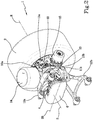
Figure 2 is a perspective view of an independent suspension object of the present invention; -
Figure 3 is a horizontal sectional view of the suspension offigure 2 . - With reference to the accompanying
figures, 1 refers overall to an independent suspension for vehicles, in particular for the transport of people and/or materials which, for the sake of disclosure simplicity, will be indicated hereinafter asindependent suspension 1. - The term "vehicle" means any type of vehicle, such as (in accordance with a non-exhaustive list) buses, couriers, trucks, lorries, special vehicles, and the like. In other words, the term vehicle can mean light, medium or heavy commercial vehicles. For example, the term vehicle refers to transport means adapted to transport people or large volumes of material (free or boxed) as well as transport luggage. Furthermore, the term vehicle can be understood as a vehicle equipped with a lowered platform.
- The
independent suspension 1 comprises ahub 2 defining a rotation axis "R" of awheel 3 of the vehicle. - The
independent suspension 1 further comprises anelectric motor 4, operatively connected to thehub 2 and configured to put thehub 2 itself in rotation. - The
electric motor 4 extends along a development axis "S" thereof parallel to the rotation axis "R" of thehub 2. - Preferably, the development axis "S" of the
electric motor 4 and the rotation axis "R" of thehub 2 lie on a plane obliquely arranged with respect to a horizontal or vertical reference plane passing through the rotation axis "R" of thehub 2. In other words, the development axis "S" of theelectric motor 4 is angularly positioned around the rotation axis of the hub. Preferably, the development axis "S" of theelectric motor 4 and the rotation axis "R" of thehub 2 lie on the same vertical plane. In other words, the development axis "S" of the electric motor and the rotation axis "R" of thehub 2 lie on the vertical reference plane. - As for example shown in the accompanying figures, the development axis "S" of the
electric motor 4 and the rotation axis "R" of thehub 2 lie on the same horizontal plane "O". In other words, the development axis "S" of theelectric motor 4 and the rotation axis "R" of thehub 2 lie on the horizontal reference plane. - In other words, the development axis "S" of the
electric motor 4 can have any angular positioning with respect to the rotation axis "R" of thehub 2 as a function of the constructional needs of the vehicle on which theindependent suspension 1 must be installed and in particular as a function of the volume to be obtained from the loading plane of the vehicle. Advantageously, the above solutions allow to obtain anindependent suspension 1 equipped with a highly compact structure and capable of saving space in a lowered platform (i.e., in a loading plane) of a vehicle. In other words, the particular positioning of theelectric motor 4 with respect to the rest of the structure of theindependent suspension 1 allows to obtain a greater volume in a loading plane, thus allowing a greater load of materials or luggage. - Furthermore, the compactness of the
independent suspension 1 allows easy access or transit to the lowered platform, for example in the case of a vehicle equipped with a lowered platform and access tailgate. In other words, theindependent suspension 1 advantageously allows access and/or transit in the rear area of the vehicle while keeping the platform lowered (without level changes). - As for example shown in the accompanying figures, the
independent suspension 1 comprises atransmission system 5 for putting thewheel 3hub 2 in rotation by means of theelectric motor 4. Such atransmission system 5 comprises areducer 6, aninput shaft 7a, and anoutput shaft 7b. Thereducer 6 develops along a development axis "S6" thereof perpendicular to the rotation axis "R" and development axis "S". - The
input shaft 7a is interposed between theelectric motor 4 and thereducer 6. In other words, theinput shaft 7a is the motor shaft of the electric motor 4 (or it is a further shaft connected or connectable to the motor shaft). The development axis of theinput shaft 7a coincides with the development axis "S" of theelectric motor 4. - The
output shaft 7b is interposed between thereducer 6 and thehub 2. In other words, theoutput shaft 7b is the transmission shaft configured to transmit the rotation movement of thefirst input shaft 7a so as to put thehub 2 in rotation. The development axis of theoutput shaft 7b coincides with the rotation axis "R" of thehub 2. - Preferably, the ends of the
reducer 6 coincide with the respective development axes "S" of theelectric motor 4 and the rotation axis "R" of thehub 2. In other words, thereducer 6 defines a spacer element between the development axis "S" (i.e., theinput shaft 7a) and the rotation axis "R" (i.e., theoutput shaft 7b). - Advantageously, the distance at which the electric motor and rotation axis of the hub are spaced allows a more compact suspension to be obtained. The
reducer 6 is therefore equipped with kinematics suitable for the transmission of the rotational motion between theinput shaft 7a and theoutput shaft 7b. - Preferably, at least the
input shaft 7a and thereducer 6 are equipped with cylindrical gears geared to each other. - Alternatively, at least the
input shaft 7a and thereducer 6 realize a motion transmission by means of drive belts. - The
output shaft 7b is connected to thehub 2 andreducer 6 by means of respective junction elements.Such junction elements 9 are manufactured, as shown for example in the accompanying figures, in the form of homokinetic joints. The term homokinetic joints means joints capable of maintaining a constant drive ratio between theinput shaft 7a and theoutput shaft 7b. In particular, the homokinetic joint allows the drive ratio to be kept constant regardless of the inclination of the shafts with respect to the other components while the vehicle is travelling. In other words, the homokinetic joint connecting theoutput shaft 7b with thereducer 6 ensures the transmission of the rotational motion to theoutput shaft 7b whatever the inclination thereof with respect to the components of thereducer 6. Similarly, the homokinetic joint connecting theoutput shaft 7b with thehub 2 ensures the transmission of the rotational motion of thehub 2 whatever the inclination of the output shaft with respect to thehub 2. Advantageously, in the case of holes in the ground or other undesired vibrations, the homokinetic joint allows to maintain the desired transmission ratio. - Advantageously, the homokinetic joint is slim and ensures high performance.
- In use, the
input shaft 7a transmits the rotational motion to thereducer 6 by means of the cylindrical gear thereof (or by using the drive belt). In other words, the cylindrical gear puts the cylindrical gear of thereducer 6 in rotation which thus puts theoutput shaft 7b in rotation which, taking advantage of the use of thehomokinetic junction elements 9, puts thehub 2 in rotation. - The entire solution described above allows to ensure a high compactness of the
transmission system 5 thus guaranteeing the desired dimensional features for theindependent suspension 1 in order to obtain as much space as possible within a lowered plane of a vehicle of the type previously discussed. - Preferably, the
transmission system 5 can be of the single speed type (such as that described above) - Preferably, the
transmission system 5 can be of the multiple speed type. In other words, the components previously described for thetransmission system 5 can be modified as a function of the fact that it is intended to obtain a multi-gear transmission system. - Preferably, the
transmission system 5 comprises anepicyclic gear system 5a, i.e., a planetary gear (as for example shown infigure 3 ). - The
epicyclic gear system 5a is installed on thehub 2 and is configured to reduce the torque transmitted through theinput shaft 7b (i.e., through the junction elements 9). In other words, theepicyclic gear system 5a has the possibility of supporting the transmission even during steering. It is thereby possible to obtain a steering system. - Preferably, and as depicted in the accompanying figures, the
independent suspension 1 comprises asupport element 10 provided with a first 10a and asecond support portion 10b defining, respectively, a hinge point (11a and 11b), substantially horizontal, for a respective cross arm (12a and 12b) end. Thefirst support portion 10a is arranged in an upper portion of thesupport element 10 and thesecond support portion 10b is arranged in a lower portion of thesupport element 10. - Preferably, the hinge points 11a and 11b are defined by pins rigidly constrained to the
respective support portion respective cross arm - Preferably, and as shown in the attached figures, the
support element 10 is equipped with aspecial opening 13 configured to allow the passage of thejunction element 9 to couple thereducer 6 to thehub 2. In other words, theopening 13 is configured to allow the accommodation of the homokinetic joint so as to allow the connection of theoutput shaft 7b to thehub 3 in order to transmit the rotation movement. - Preferably, the
independent suspension 1 comprises a steering spindle (not shown) comprising an outer portion, defining the rotation axis "R" of thehub 2 of thevehicle wheel 3, and an inner portion extending transversely to the outer portion along a steering axis. Preferably, the steering axis is transverse to the rotation axis of thehub 2, more preferably inclined with respect thereto by an angle in the range between 60° and 90°, more preferably between 75° and 85°, in particular of about 80°. - In such a configuration, the
support element 10 is rotatably coupled to the inner portion of the spindle to allow a relative rotation around the steering axis. - In other words, the
independent suspension 1 described in the present invention can be of the non-steering type or of the steering type. - Preferably, the
first support portion 10a is equipped with aspring 14 or damper and the second support portion can be provided with a shock absorber (not shown). Generally, saidspring 14 and shock absorber are connected or connectable to the vehicle frame and define a pneumatic suspension system. - Preferably, if the development axis "S" of the
electric motor 4 is positioned along the vertical reference plane, instead of a spring 14 (as theelectric motor 4 is present) a cylinder defining a hydraulic suspension system is present. - As shown in the accompanying figures, the
independent suspension 1 can further be equipped with anactuator 15 for the brake. - Advantageously and as already underlined above, the
independent suspension 1 object of the present invention is capable of overcoming the drawbacks emerging from the prior art. - Advantageously, the
independent suspension 1 has a compact structure suitable for obtaining additional volumes inside a loading plane of a vehicle, in particular of a lowered platform vehicle. - Furthermore, the solution described above is particularly versatile, resulting in a structure adaptable as a function of the construction needs of the reference vehicle.
- Advantageously, the
independent suspension 1 also results in a simplified structure which can be easily assembled/disassembled and therefore has no particularly difficult maintenance. - Advantageously, the particular positioning of the
electric motor 4 with respect to thewheel 3hub 2 allows to obtain a greater corridor (i.e., the space between two axles coupled along the same "axis") with respect to that obtainable from the known independent axles, in which the axis of the electric motor tends to coincide with the rotation axis of the hub (in other words the electric motor occupies the space which is instead obtained with the present invention). - The present invention further relates to a vehicle for loading people and/or materials comprising an independent suspension 1 (according to one or more of the previously described forms) for each
wheel 3 of the vehicle itself. In other words, if the vehicle has, for example, eight wheels (i.e., four pairs of wheels 3), the same will further be equipped with eightindependent axles 1 such as those described above. - The
independent suspensions 1 coupled together have a corridor "C" between 500 and 1000 mm so as to define an auxiliary load volume. In other words, the distance between two coupledwheels 3 obtained by using theindependent suspension 1 described above allows to obtain a greater volume with respect to that which would normally be obtainable from the known solutions in which the same would be absent or so small so as not to be usable or easily reachable. Such a solution is particularly advantageous for heavy vehicles with a lowered platform. - Preferably, the vehicle further comprises a loading plane for loading luggage or other materials having a main load volume and a number of auxiliary load volumes equal to the number of pairs of
independent axles 1 present in the vehicle. Each auxiliary load volume has a width equal to the corridor "C". It follows that the length of each auxiliary load volume (i.e., the dimension parallel to the main development dimension of the vehicle) is equal to the extension of the structure of theindependent suspension 1. Preferably, the vehicle can further comprise a tailgate for loading people and/or materials. In other words, the vehicle allows access and transit in a rear area, keeping the platform lowered without requiring level changes. Preferably, the vehicle further comprises a plane configured for supporting passengers equipped, near the independent suspensions, with a width substantially equal to the corridor "C" allowing to obtain an auxiliary passenger support surface and therefore a greater overall support surface. Advantageously, the vehicle described above has a lowered plane equipped with a greater usable volume with respect to that of the known heavy vehicles. In other words, the vehicle described above allows to transport a greater load with respect to that of vehicles of a known type. Furthermore, the vehicle described above allows to transport a greater number of people and/or luggage (in the case of buses for example) and therefore of materials (in the case of trucks for the transport of goods and the like). - Advantageously, the present invention provides an independent suspension and a vehicle which allow to increase the maximum load transportable by the vehicle itself.
- Advantageously, the present invention provides an independent suspension and a vehicle which allow to increase the useful surface on which a passenger or other user can walk.
- Advantageously, the independent suspension can be used for small wheels (for example those of a car or small vehicle) or for larger wheels (such as buses or the like).
- Advantageously, the independent suspension allows to increase the free space of the central body of vehicles such as logistics or special means. Advantageously, the present invention is applicable on any suspension having a structural diagram different from that illustrated in the accompanying figures.
Claims (17)
- Independent suspension (1) for vehicles, in particular for the transport of people and/or materials, comprising:- a hub (2) defining a rotation axis (R) of the vehicle wheel (3);- an electric motor (4), operatively connected to said hub (2) and configured to put said hub (2) in rotation, said electric motor (4) extending along a development axis (S) thereof;characterized in that said development axis (S) of the electric motor (4) is parallel to the rotation axis (R) of the hub (2).
- Independent suspension (1) according to claim 1, further comprising a transmission system (5), for putting the wheel (3) hub (2) in rotation by means of said electric motor (4), comprising a speed reducer (6) developing along a development axis (S6) thereof perpendicular to said rotation (R) and development axis (S), an input shaft (7a) between the electric motor (4) and the reducer (6) and an output shaft (7b) between the reducer (6) and the hub (2).
- Independent suspension (1) according to claim 2, wherein at least said input shaft (7a) and said reducer (6) are equipped with cylindrical gears geared to each other or realize a motion transmission by means of drive belts.
- Independent suspension (1) according to one or more of the preceding claims, wherein said development axis (S) of the electric motor (4) and said rotation axis (R) of the hub (2) lie on a plane obliquely arranged with respect to a horizontal or vertical reference plane passing through said rotation axis (R) of the hub (2).
- Independent suspension (1) according to one or more of the preceding claims, wherein said development axis (S) of the electric motor (4) and said rotation axis (R) of the hub (2) lie on the same vertical plane or on the same horizontal plane (O).
- Independent suspension (1) according to one or more of the preceding claims, comprising a support element (10) provided with a first and a second support portion (10a, 10b) defining a substantially horizontal hinge point (11a, 11b) for a respective cross arm (12a, 12b) end.
- Independent suspension (1) according to one or more of claims 2-6, wherein said output shaft (7b) is connected to said hub (3) and to said reducer (6) by means of respective junction elements (9) manufactured in the form of homokinetic joints.
- Independent suspension (1) according to claims 6 and 7, wherein said support element (10) is provided with a special opening (13) configured to allow passage and accommodate said junction element (9).
- Independent suspension (1) according to one or more of claims 2-8, wherein said transmission system (5) is of the single speed or multiple speed type.
- Independent suspension (1) according to one or more of claims 2-9, wherein said speed transmission system (5) comprises an epicyclic gear system (5a), i.e. a planetary gear, installed on the hub (2).
- Independent suspension (1) according to one or more of the preceding claims, comprising a steering spindle comprising an outer portion, defining said rotation axis of the vehicle wheel (3) hub (2), and an inner portion extending transversely to the outer portion along a steering axis.
- Independent suspension (1) according to claims 6 and 11, wherein the support element (10) is rotatably coupled to the inner portion of the spindle to allow a relative rotation around the steering axis.
- Independent suspension (1) according to one or more of claims 6-12, wherein said first bearing portion (10a) is provided with a spring (14) or damper and wherein said second bearing portion (10b) is provided with a shock absorber.
- Vehicle for the transport of persons and/or materials comprising an independent suspension (1) according to one or more of the preceding claims for each wheel (3) of the vehicle itself, said independent suspensions (1) coupled to each other having a corridor (C) between 500 and 1000 mm so as to define an auxiliary load volume.
- Vehicle according to claim 14, further comprising a loading platform for loading luggage or other materials having a main load volume and a number of auxiliary load volumes equal to the number of pair of independent suspension (1) present in the vehicle, each auxiliary load volume having a width equal to said corridor (C).
- Vehicle according to claim 14 or 15, further comprising a plane configured to support passengers equipped, near said independent suspensions, with an abutment width substantially equal to the corridor (C).
- Vehicle according to one or more of claims 15-16, further comprising a tailgate for loading people and/or materials.
Applications Claiming Priority (1)
| Application Number | Priority Date | Filing Date | Title |
|---|---|---|---|
| IT102020000006940A IT202000006940A1 (en) | 2020-04-02 | 2020-04-02 | INDEPENDENT SUSPENSION |
Publications (3)
| Publication Number | Publication Date |
|---|---|
| EP3888956A1 true EP3888956A1 (en) | 2021-10-06 |
| EP3888956B1 EP3888956B1 (en) | 2025-04-09 |
| EP3888956C0 EP3888956C0 (en) | 2025-04-09 |
Family
ID=70978455
Family Applications (1)
| Application Number | Title | Priority Date | Filing Date |
|---|---|---|---|
| EP21165122.9A Active EP3888956B1 (en) | 2020-04-02 | 2021-03-26 | Independent vehicle suspension |
Country Status (5)
| Country | Link |
|---|---|
| US (1) | US11999239B2 (en) |
| EP (1) | EP3888956B1 (en) |
| KR (1) | KR20210124065A (en) |
| CN (1) | CN113492670A (en) |
| IT (1) | IT202000006940A1 (en) |
Cited By (1)
| Publication number | Priority date | Publication date | Assignee | Title |
|---|---|---|---|---|
| IT202300002526A1 (en) * | 2023-02-15 | 2024-08-15 | Brist Axle Systems S R L | INDEPENDENT SUSPENSION |
Families Citing this family (1)
| Publication number | Priority date | Publication date | Assignee | Title |
|---|---|---|---|---|
| KR20230112937A (en) * | 2022-01-21 | 2023-07-28 | 현대모비스 주식회사 | Corner module apparatus for vehicle |
Citations (4)
| Publication number | Priority date | Publication date | Assignee | Title |
|---|---|---|---|---|
| EP2075175A1 (en) * | 2007-12-27 | 2009-07-01 | Iveco France S.A. | Urban transport vehicle with small wheels |
| ITPC20100003A1 (en) * | 2010-01-11 | 2011-07-12 | Aeroconsult Internat Srl | MINIBUS WITH VARIABLE SET UP AND INTEGRAL HYBRID TRACTION |
| WO2017152290A1 (en) * | 2016-03-10 | 2017-09-14 | Electrameccanica Vehicles Corp. | Tensioner for a suspension swing arm |
| US20170320382A1 (en) * | 2016-05-09 | 2017-11-09 | Bluegentech Llc | Motor gearbox assembly |
Family Cites Families (20)
| Publication number | Priority date | Publication date | Assignee | Title |
|---|---|---|---|---|
| US3118687A (en) * | 1962-06-20 | 1964-01-21 | Gen Motors Corp | Independent front wheel suspension |
| US4515390A (en) * | 1983-04-11 | 1985-05-07 | Greenberg William H | Chassis and suspension system for vehicles |
| US4610461A (en) * | 1985-06-17 | 1986-09-09 | Matthew Guzzetta | Steering system for elimination of bump steering in independent wheel suspension systems |
| US7597169B2 (en) * | 2001-12-07 | 2009-10-06 | Gm Global Technology Operations, Inc. | Wheel module |
| US6793035B2 (en) * | 2002-03-15 | 2004-09-21 | Meritor Heavy Vehicle Technology, Llc | Semi-independent swing arm suspension system for a low floor vehicle |
| US7703780B2 (en) * | 2003-09-30 | 2010-04-27 | Toyota Jidosha Kabushiki Kaisha | Wheel supporting apparatus improving ride comfort of vehicle |
| JP5565388B2 (en) * | 2011-03-28 | 2014-08-06 | アイシン・エィ・ダブリュ株式会社 | In-wheel motor drive device |
| CN202518082U (en) * | 2012-02-21 | 2012-11-07 | 同济大学 | Wheel rim electric driving device for motor-driven vehicle |
| KR101441813B1 (en) * | 2013-06-25 | 2014-09-18 | 현대위아 주식회사 | Device for driving rear wheel of electric vehicle |
| JP2017171272A (en) * | 2016-03-22 | 2017-09-28 | Ntn株式会社 | In-wheel motor drive device |
| ITUA20163542A1 (en) * | 2016-05-18 | 2017-11-18 | Brist Axle Systems S R L | INDEPENDENT SUSPENSION FOR VEHICLES, IN PARTICULAR A SUSPENSION FOR A STEERING WHEEL OF VEHICLES |
| JP6813370B2 (en) * | 2017-01-18 | 2021-01-13 | Ntn株式会社 | In-wheel motor drive |
| CN106976368A (en) * | 2017-05-15 | 2017-07-25 | 厦门金龙联合汽车工业有限公司 | A kind of achievable independent suspension frame unit for turning to driving function |
| DE102017214640A1 (en) * | 2017-08-22 | 2019-02-28 | Zf Friedrichshafen Ag | Vehicle axle with a centrally arranged drive unit |
| JP2019043177A (en) * | 2017-08-29 | 2019-03-22 | トヨタ自動車株式会社 | Vehicular in-wheel motor drive unit |
| JP2020028136A (en) * | 2018-08-09 | 2020-02-20 | Ntn株式会社 | Vehicle motor drive device |
| JP7048460B2 (en) * | 2018-09-10 | 2022-04-05 | Ntn株式会社 | In-wheel motor drive |
| US20200223270A1 (en) * | 2019-01-11 | 2020-07-16 | Tenneco Automotive Operating Company Inc. | Active Camber Control Systems and Methods |
| CN209870094U (en) * | 2019-01-28 | 2019-12-31 | 郑州宇通客车股份有限公司 | Integrated wheel-side driving system of independent suspension and vehicle |
| CN110435381B (en) * | 2019-07-11 | 2024-05-10 | 浙江亚太机电股份有限公司 | Low-floor chassis platform integrated with hub motor |
-
2020
- 2020-04-02 IT IT102020000006940A patent/IT202000006940A1/en unknown
-
2021
- 2021-03-26 EP EP21165122.9A patent/EP3888956B1/en active Active
- 2021-03-26 US US17/213,912 patent/US11999239B2/en active Active
- 2021-04-01 KR KR1020210042807A patent/KR20210124065A/en active Pending
- 2021-04-02 CN CN202110358842.4A patent/CN113492670A/en active Pending
Patent Citations (4)
| Publication number | Priority date | Publication date | Assignee | Title |
|---|---|---|---|---|
| EP2075175A1 (en) * | 2007-12-27 | 2009-07-01 | Iveco France S.A. | Urban transport vehicle with small wheels |
| ITPC20100003A1 (en) * | 2010-01-11 | 2011-07-12 | Aeroconsult Internat Srl | MINIBUS WITH VARIABLE SET UP AND INTEGRAL HYBRID TRACTION |
| WO2017152290A1 (en) * | 2016-03-10 | 2017-09-14 | Electrameccanica Vehicles Corp. | Tensioner for a suspension swing arm |
| US20170320382A1 (en) * | 2016-05-09 | 2017-11-09 | Bluegentech Llc | Motor gearbox assembly |
Cited By (3)
| Publication number | Priority date | Publication date | Assignee | Title |
|---|---|---|---|---|
| IT202300002526A1 (en) * | 2023-02-15 | 2024-08-15 | Brist Axle Systems S R L | INDEPENDENT SUSPENSION |
| EP4417444A1 (en) * | 2023-02-15 | 2024-08-21 | Brist Axle Systems S.R.L. | Independent suspension |
| US12508859B2 (en) | 2023-02-15 | 2025-12-30 | Brist Axle Systems S.R.L. | Independent suspension |
Also Published As
| Publication number | Publication date |
|---|---|
| US20210309098A1 (en) | 2021-10-07 |
| EP3888956B1 (en) | 2025-04-09 |
| CN113492670A (en) | 2021-10-12 |
| US11999239B2 (en) | 2024-06-04 |
| IT202000006940A1 (en) | 2021-10-02 |
| EP3888956C0 (en) | 2025-04-09 |
| KR20210124065A (en) | 2021-10-14 |
Similar Documents
| Publication | Publication Date | Title |
|---|---|---|
| EP3888956B1 (en) | Independent vehicle suspension | |
| US7232004B2 (en) | Low load floor motor vehicle | |
| US5188195A (en) | Vehicle driving wheel suspension system | |
| US3027959A (en) | Mobile load carrying apparatus | |
| US20120018984A1 (en) | Independent dual wheel direct drive axles, between the duals gear box, and independent servo drive steering for between the dual direct drive suspensions | |
| CN113119678B (en) | Unmanned transport vehicles | |
| US20130162007A1 (en) | Independent dual wheel direct drive axles, between the duals gear box, and independent servo drive steering for between the dual direct drive suspensions | |
| JPH0796372B2 (en) | All-wheel drive off-road vehicle | |
| US4062582A (en) | Truck construction | |
| EP1344661B1 (en) | A suspension system for a low floor vehicle | |
| KR920002740B1 (en) | car | |
| GB2276128A (en) | Goods vehicles with separable cab and load space sections. | |
| US12508859B2 (en) | Independent suspension | |
| EP3785949A1 (en) | Driving assembly for a heavy vehicle | |
| IT202000004966A1 (en) | INDEPENDENT SUSPENSION | |
| JPS5830878A (en) | Car | |
| EP4534303A1 (en) | Independent suspension | |
| WO2019213015A1 (en) | Articulated vehicles with payload-positioning systems | |
| US6659217B2 (en) | Drive assembly for low floor vehicle | |
| JP2952474B2 (en) | Auxiliary bogie for vehicles | |
| RU2189911C2 (en) | Wheeled vehicle balance truck | |
| WO2023152533A1 (en) | Transverse self-balancing vehicle | |
| JPH106843A (en) | Trackless industrial vehicle steering mechanism | |
| JPH09301008A (en) | Transport trolley with wheels with differential gear mechanism | |
| RU2002103560A (en) | SINGLE WHEEL VEHICLE |
Legal Events
| Date | Code | Title | Description |
|---|---|---|---|
| PUAI | Public reference made under article 153(3) epc to a published international application that has entered the european phase |
Free format text: ORIGINAL CODE: 0009012 |
|
| STAA | Information on the status of an ep patent application or granted ep patent |
Free format text: STATUS: THE APPLICATION HAS BEEN PUBLISHED |
|
| AK | Designated contracting states |
Kind code of ref document: A1 Designated state(s): AL AT BE BG CH CY CZ DE DK EE ES FI FR GB GR HR HU IE IS IT LI LT LU LV MC MK MT NL NO PL PT RO RS SE SI SK SM TR |
|
| STAA | Information on the status of an ep patent application or granted ep patent |
Free format text: STATUS: REQUEST FOR EXAMINATION WAS MADE |
|
| 17P | Request for examination filed |
Effective date: 20220322 |
|
| RBV | Designated contracting states (corrected) |
Designated state(s): AL AT BE BG CH CY CZ DE DK EE ES FI FR GB GR HR HU IE IS IT LI LT LU LV MC MK MT NL NO PL PT RO RS SE SI SK SM TR |
|
| STAA | Information on the status of an ep patent application or granted ep patent |
Free format text: STATUS: EXAMINATION IS IN PROGRESS |
|
| 17Q | First examination report despatched |
Effective date: 20240516 |
|
| GRAP | Despatch of communication of intention to grant a patent |
Free format text: ORIGINAL CODE: EPIDOSNIGR1 |
|
| STAA | Information on the status of an ep patent application or granted ep patent |
Free format text: STATUS: GRANT OF PATENT IS INTENDED |
|
| INTG | Intention to grant announced |
Effective date: 20241219 |
|
| GRAS | Grant fee paid |
Free format text: ORIGINAL CODE: EPIDOSNIGR3 |
|
| GRAA | (expected) grant |
Free format text: ORIGINAL CODE: 0009210 |
|
| STAA | Information on the status of an ep patent application or granted ep patent |
Free format text: STATUS: THE PATENT HAS BEEN GRANTED |
|
| AK | Designated contracting states |
Kind code of ref document: B1 Designated state(s): AL AT BE BG CH CY CZ DE DK EE ES FI FR GB GR HR HU IE IS IT LI LT LU LV MC MK MT NL NO PL PT RO RS SE SI SK SM TR |
|
| REG | Reference to a national code |
Ref country code: GB Ref legal event code: FG4D |
|
| REG | Reference to a national code |
Ref country code: CH Ref legal event code: EP |
|
| REG | Reference to a national code |
Ref country code: DE Ref legal event code: R096 Ref document number: 602021028756 Country of ref document: DE |
|
| REG | Reference to a national code |
Ref country code: IE Ref legal event code: FG4D |
|
| U01 | Request for unitary effect filed |
Effective date: 20250414 |
|
| U07 | Unitary effect registered |
Designated state(s): AT BE BG DE DK EE FI FR IT LT LU LV MT NL PT RO SE SI Effective date: 20250422 |
|
| PG25 | Lapsed in a contracting state [announced via postgrant information from national office to epo] |
Ref country code: ES Free format text: LAPSE BECAUSE OF FAILURE TO SUBMIT A TRANSLATION OF THE DESCRIPTION OR TO PAY THE FEE WITHIN THE PRESCRIBED TIME-LIMIT Effective date: 20250409 |
|
| PG25 | Lapsed in a contracting state [announced via postgrant information from national office to epo] |
Ref country code: NO Free format text: LAPSE BECAUSE OF FAILURE TO SUBMIT A TRANSLATION OF THE DESCRIPTION OR TO PAY THE FEE WITHIN THE PRESCRIBED TIME-LIMIT Effective date: 20250709 Ref country code: GR Free format text: LAPSE BECAUSE OF FAILURE TO SUBMIT A TRANSLATION OF THE DESCRIPTION OR TO PAY THE FEE WITHIN THE PRESCRIBED TIME-LIMIT Effective date: 20250710 |
|
| PG25 | Lapsed in a contracting state [announced via postgrant information from national office to epo] |
Ref country code: PL Free format text: LAPSE BECAUSE OF FAILURE TO SUBMIT A TRANSLATION OF THE DESCRIPTION OR TO PAY THE FEE WITHIN THE PRESCRIBED TIME-LIMIT Effective date: 20250409 |
|
| PG25 | Lapsed in a contracting state [announced via postgrant information from national office to epo] |
Ref country code: HR Free format text: LAPSE BECAUSE OF FAILURE TO SUBMIT A TRANSLATION OF THE DESCRIPTION OR TO PAY THE FEE WITHIN THE PRESCRIBED TIME-LIMIT Effective date: 20250409 |
|
| PG25 | Lapsed in a contracting state [announced via postgrant information from national office to epo] |
Ref country code: RS Free format text: LAPSE BECAUSE OF FAILURE TO SUBMIT A TRANSLATION OF THE DESCRIPTION OR TO PAY THE FEE WITHIN THE PRESCRIBED TIME-LIMIT Effective date: 20250709 |
|
| PG25 | Lapsed in a contracting state [announced via postgrant information from national office to epo] |
Ref country code: IS Free format text: LAPSE BECAUSE OF FAILURE TO SUBMIT A TRANSLATION OF THE DESCRIPTION OR TO PAY THE FEE WITHIN THE PRESCRIBED TIME-LIMIT Effective date: 20250809 |
|
| PG25 | Lapsed in a contracting state [announced via postgrant information from national office to epo] |
Ref country code: SM Free format text: LAPSE BECAUSE OF FAILURE TO SUBMIT A TRANSLATION OF THE DESCRIPTION OR TO PAY THE FEE WITHIN THE PRESCRIBED TIME-LIMIT Effective date: 20250409 |
|
| PG25 | Lapsed in a contracting state [announced via postgrant information from national office to epo] |
Ref country code: CZ Free format text: LAPSE BECAUSE OF FAILURE TO SUBMIT A TRANSLATION OF THE DESCRIPTION OR TO PAY THE FEE WITHIN THE PRESCRIBED TIME-LIMIT Effective date: 20250409 |
|
| PG25 | Lapsed in a contracting state [announced via postgrant information from national office to epo] |
Ref country code: SK Free format text: LAPSE BECAUSE OF FAILURE TO SUBMIT A TRANSLATION OF THE DESCRIPTION OR TO PAY THE FEE WITHIN THE PRESCRIBED TIME-LIMIT Effective date: 20250409 |
|
| PLBE | No opposition filed within time limit |
Free format text: ORIGINAL CODE: 0009261 |
|
| STAA | Information on the status of an ep patent application or granted ep patent |
Free format text: STATUS: NO OPPOSITION FILED WITHIN TIME LIMIT |
|
| REG | Reference to a national code |
Ref country code: CH Ref legal event code: L10 Free format text: ST27 STATUS EVENT CODE: U-0-0-L10-L00 (AS PROVIDED BY THE NATIONAL OFFICE) Effective date: 20260218 |
|
| 26N | No opposition filed |
Effective date: 20260112 |
|
| U20 | Renewal fee for the european patent with unitary effect paid |
Year of fee payment: 6 Effective date: 20260226 |
|
| PGFP | Annual fee paid to national office [announced via postgrant information from national office to epo] |
Ref country code: GB Payment date: 20260304 Year of fee payment: 6 |
|
| PGFP | Annual fee paid to national office [announced via postgrant information from national office to epo] |
Ref country code: TR Payment date: 20260309 Year of fee payment: 6 |