EP2075175A1 - Urban transport vehicle with small wheels - Google Patents
Urban transport vehicle with small wheels Download PDFInfo
- Publication number
- EP2075175A1 EP2075175A1 EP07124104A EP07124104A EP2075175A1 EP 2075175 A1 EP2075175 A1 EP 2075175A1 EP 07124104 A EP07124104 A EP 07124104A EP 07124104 A EP07124104 A EP 07124104A EP 2075175 A1 EP2075175 A1 EP 2075175A1
- Authority
- EP
- European Patent Office
- Prior art keywords
- vehicle according
- wheel
- wheels
- vehicle
- axles
- Prior art date
- Legal status (The legal status is an assumption and is not a legal conclusion. Google has not performed a legal analysis and makes no representation as to the accuracy of the status listed.)
- Granted
Links
- 238000010276 construction Methods 0.000 description 1
- 238000010586 diagram Methods 0.000 description 1
- 230000003287 optical effect Effects 0.000 description 1
Images


Classifications
-
- B—PERFORMING OPERATIONS; TRANSPORTING
- B62—LAND VEHICLES FOR TRAVELLING OTHERWISE THAN ON RAILS
- B62D—MOTOR VEHICLES; TRAILERS
- B62D47/00—Motor vehicles or trailers predominantly for carrying passengers
- B62D47/02—Motor vehicles or trailers predominantly for carrying passengers for large numbers of passengers, e.g. omnibus
-
- B—PERFORMING OPERATIONS; TRANSPORTING
- B60—VEHICLES IN GENERAL
- B60K—ARRANGEMENT OR MOUNTING OF PROPULSION UNITS OR OF TRANSMISSIONS IN VEHICLES; ARRANGEMENT OR MOUNTING OF PLURAL DIVERSE PRIME-MOVERS IN VEHICLES; AUXILIARY DRIVES FOR VEHICLES; INSTRUMENTATION OR DASHBOARDS FOR VEHICLES; ARRANGEMENTS IN CONNECTION WITH COOLING, AIR INTAKE, GAS EXHAUST OR FUEL SUPPLY OF PROPULSION UNITS IN VEHICLES
- B60K17/00—Arrangement or mounting of transmissions in vehicles
- B60K17/04—Arrangement or mounting of transmissions in vehicles characterised by arrangement, location, or kind of gearing
- B60K17/043—Transmission unit disposed in on near the vehicle wheel, or between the differential gear unit and the wheel
-
- B—PERFORMING OPERATIONS; TRANSPORTING
- B60—VEHICLES IN GENERAL
- B60K—ARRANGEMENT OR MOUNTING OF PROPULSION UNITS OR OF TRANSMISSIONS IN VEHICLES; ARRANGEMENT OR MOUNTING OF PLURAL DIVERSE PRIME-MOVERS IN VEHICLES; AUXILIARY DRIVES FOR VEHICLES; INSTRUMENTATION OR DASHBOARDS FOR VEHICLES; ARRANGEMENTS IN CONNECTION WITH COOLING, AIR INTAKE, GAS EXHAUST OR FUEL SUPPLY OF PROPULSION UNITS IN VEHICLES
- B60K7/00—Disposition of motor in, or adjacent to, traction wheel
- B60K7/0007—Disposition of motor in, or adjacent to, traction wheel the motor being electric
-
- B—PERFORMING OPERATIONS; TRANSPORTING
- B62—LAND VEHICLES FOR TRAVELLING OTHERWISE THAN ON RAILS
- B62D—MOTOR VEHICLES; TRAILERS
- B62D31/00—Superstructures for passenger vehicles
- B62D31/02—Superstructures for passenger vehicles for carrying large numbers of passengers, e.g. omnibus
-
- B—PERFORMING OPERATIONS; TRANSPORTING
- B62—LAND VEHICLES FOR TRAVELLING OTHERWISE THAN ON RAILS
- B62D—MOTOR VEHICLES; TRAILERS
- B62D61/00—Motor vehicles or trailers, characterised by the arrangement or number of wheels, not otherwise provided for, e.g. four wheels in diamond pattern
- B62D61/10—Motor vehicles or trailers, characterised by the arrangement or number of wheels, not otherwise provided for, e.g. four wheels in diamond pattern with more than four wheels
-
- B—PERFORMING OPERATIONS; TRANSPORTING
- B60—VEHICLES IN GENERAL
- B60K—ARRANGEMENT OR MOUNTING OF PROPULSION UNITS OR OF TRANSMISSIONS IN VEHICLES; ARRANGEMENT OR MOUNTING OF PLURAL DIVERSE PRIME-MOVERS IN VEHICLES; AUXILIARY DRIVES FOR VEHICLES; INSTRUMENTATION OR DASHBOARDS FOR VEHICLES; ARRANGEMENTS IN CONNECTION WITH COOLING, AIR INTAKE, GAS EXHAUST OR FUEL SUPPLY OF PROPULSION UNITS IN VEHICLES
- B60K7/00—Disposition of motor in, or adjacent to, traction wheel
- B60K2007/0046—Disposition of motor in, or adjacent to, traction wheel the motor moving together with the vehicle body, i.e. moving independently from the wheel axle
-
- B—PERFORMING OPERATIONS; TRANSPORTING
- B60—VEHICLES IN GENERAL
- B60K—ARRANGEMENT OR MOUNTING OF PROPULSION UNITS OR OF TRANSMISSIONS IN VEHICLES; ARRANGEMENT OR MOUNTING OF PLURAL DIVERSE PRIME-MOVERS IN VEHICLES; AUXILIARY DRIVES FOR VEHICLES; INSTRUMENTATION OR DASHBOARDS FOR VEHICLES; ARRANGEMENTS IN CONNECTION WITH COOLING, AIR INTAKE, GAS EXHAUST OR FUEL SUPPLY OF PROPULSION UNITS IN VEHICLES
- B60K7/00—Disposition of motor in, or adjacent to, traction wheel
- B60K2007/0061—Disposition of motor in, or adjacent to, traction wheel the motor axle being parallel to the wheel axle
-
- B—PERFORMING OPERATIONS; TRANSPORTING
- B60—VEHICLES IN GENERAL
- B60L—PROPULSION OF ELECTRICALLY-PROPELLED VEHICLES; SUPPLYING ELECTRIC POWER FOR AUXILIARY EQUIPMENT OF ELECTRICALLY-PROPELLED VEHICLES; ELECTRODYNAMIC BRAKE SYSTEMS FOR VEHICLES IN GENERAL; MAGNETIC SUSPENSION OR LEVITATION FOR VEHICLES; MONITORING OPERATING VARIABLES OF ELECTRICALLY-PROPELLED VEHICLES; ELECTRIC SAFETY DEVICES FOR ELECTRICALLY-PROPELLED VEHICLES
- B60L2220/00—Electrical machine types; Structures or applications thereof
- B60L2220/40—Electrical machine applications
- B60L2220/46—Wheel motors, i.e. motor connected to only one wheel
Definitions
- This invention relates to an urban transport vehicle with small wheels.
- the invention relates to all types of transport vehicles whose route involves at least one station stop, during which people are likely to board the vehicle and also alight from it. It relates to such a vehicle, which may or may not be driven in a dedicated lane, in particular by means of electric wires, rails or even optical means.
- the invention relates to transport vehicles in category M3 according to European Directive 70/156/CEE.
- the vehicle is likely to carry at least 8 passengers, who may be sitting or standing.
- the total live load of this kind of vehicle is typically over 5 metric tons, while its overall length is over 5.5 metres.
- transport vehicles according to this invention include in particular, but not exclusively, buses or trolleybuses.
- This type of vehicle typically includes a chassis mounted on at least one axle, which supports wheels fitted with tyres.
- this vehicle body has various seats intended for passengers along its lateral sides. These seats may be single, that is they can hold just one passenger, or multiple, in that they can allow several passengers to sit next to each other.
- the aforementioned wheels are associated with wheel arches, on which some of the seats are placed.
- the rows of seats facing each other delimit a central corridor, which in particular allows passengers to move through the vehicle.
- the invention relates to a transport vehicle which is improved in relation to the prior art. Specifically it provides such a vehicle with a simplified structure, of a more modular form of construction, in which passenger comfort and ease of movement are better than in normal arrangements.
- the invention also provides such a transport vehicle with a compact high efficiency drive which can be matched with brakes of the standard type.
- Figure 1 illustrates a transport vehicle according to the invention which comprises a body 2, the front end of which is numbered 2 1 , situated on the left of the drawing, while the rear end is numbered 2 2 .
- Body 2 is fitted with three side doors, respectively front 4, middle, 5 and rear 6.
- Body 2 is supported by wheels with tyres. More specifically, there are two front axles 8 1 and 8 2 , each of which is equipped with two drive wheels, namely a first pair 10 1 and a second pair 10 2 .
- rear axles 12 1 and 12 2 each of which is equipped with two drive wheels, namely a first pair 14 1 and a second pair 14 2 .
- first pair 14 1 and a second pair 14 2 only one pair of the rear wheels might be drive wheels, specifically pair 14 1 .
- the other pair, for example 14 2 is steered through a smaller sweep angle than front wheels 10 1 and 10 2 .
- the transport vehicle according to the invention is fitted with seats 22, of any known type, which may for example be single, double, fixed or folding.
- Figure 2 illustrates more precisely two seats 22 1 and 22 2 , respectively above and close to wheel arch 18.
- all the wheels including those numbered 14 1 , have an external diameter d of between 700 and 750 mm, preferably between 730 and 740 mm and in particular close to 737 mm.
- This diameter d corresponds to a wheel with a tyre that is nominally inflated, i.e. with a pressure for example of approximately 9 bars with a load of approximately 2.5 metric tons per wheel.
- Seat 22 1 is located over wheel arch 18 and is fixed by any appropriate means. Given that the value d of the diameter of the wheel is relatively small, seat 22 1 located above wheel arch 18 lies roughly at the same height as adjacent seat 22 2 which is at a distance from said wheel arch. In other words, seat 22 1 placed above the wheel arch is not raised in relation to the other seats, so that, as will become clear below, it is not necessary to modify the arrangement of the floor near this wheel arch.
- Figure 4 illustrates a wheel 114 fitted to a vehicle according to the state of the art, whose diameter D is substantially greater than that d of wheels 10 and 14 used in the invention.
- said diameter D is usually around 974 mm.
- wheel arch 118 extending above said wheel 114 is of greater height than that of 18 in Figure 2 .
- seat 122 1 mounted on this wheel arch is higher than 122 2 which is located beside the wheel arch.
- Figure 3 is a view from above illustrating the steering-angle of wheels 14 1 . Given that they have a relatively small diameter d , the sweep of these wheels during steering is also quite small. Thus the value of this maximum sweep distance is indicated by b , which corresponds to the distance between the edge of the body and the furthest end of the wheel in its maximally pivoted position. Consequently, it follows that wheel arch 18 has a relatively small width.
- the two opposite wheel arches 18 delimit a central corridor C, of width L.
- the value of this width L of the corridor is relatively large, specifically in the region of 1200 mm.
- B denotes the maximum sweep of wheels 114, which have a diameter D.
- Said value B is greater than b according to the invention, so that the width of wheel arches 118 is much greater than that of wheel arches 18.
- corridor C' of known vehicles which is delimited by these wheel arches, has a width I which is much less than that provided by the invention, and is typically around 900 mm.
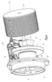
- Figures 6 and 7 illustrate a first embodiment relating to the drive for wheels 14 of small diameter according to the invention.
- This electric motor 21 which is mounted on the chassis of the vehicle.
- This electric motor 21, of a conventional type, has a rotating shaft 23 which extends obliquely with respect to the transverse axis A of rotation of the wheels. It will be noted that this motor 21 is not fixed in rotation with the wheels, at least when this rotation takes place in that transverse axis. Conversely, this motor 21 is of one piece with steering movements of the wheel on which it is mounted, namely when the wheel pivots about a substantially vertical axis.
- This motor 21 has a cylindrical body 25, the diameter D 25 of which is typically between 300 and 330 mm, and whose length L 25 is typically between 200 and 250 mm. Furthermore, the maximum rotation speed of this motor lies between 8,000 and 10,000 rpm.
- Shaft 23 acts together with a conical gear 27, of a type which is in itself known, the output 29 from which extends substantially along the aforesaid axis A.
- This output 29 extends successively through brake disk 31, disk support 33 and rim 35 of wheel 14.
- This output 29 engages an epicyclical gear train 37, of a type which is in itself known. Finally the output of this gear train 37 drives the rim, and consequently the wheel, directly.
- the reduction coefficient of the conical gear is for example between 2.5 and 3.5, in particular close to 3.
- the reduction coefficient associated with the epicyclical gear train is between 4 and 6, in particular close to 5. This being the case, the total reduction coefficient between the motor and the wheel is for example between 10 and 20, in particular close to 15.
- V indicates the "overall volume” of the braking assembly, comprising disk 31, its support 33, as well as braking member 39, of a conventional type, which is for example of a hydraulic nature.
- This volume V is roughly in the shape of a cylinder, the central axis of which is that A about which the wheels rotate, and whose diameter is defined by the distance between the central axis and the outer periphery of braking member 39.
- conical gear 27 is wholly housed within this volume V.
- epicyclical gear train 37 is housed against the rim, opposite the motor 21, and this is also advantageous in terms of overall compactness.
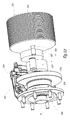
- FIGs 8 and 9 illustrate a variant embodiment of the drive for wheels 14.
- mechanical elements which are similar to those in Figures 6 and 7 are allocated the same reference numbers increased by 100.
- This motor 121 There is an electric motor 121, whose overall dimensions are slightly less than those of motor 21 in the first embodiment. Furthermore, this motor 121 has a rotation speed which is greater than that of first motor 21.
- This motor 121 has an output shaft 123 which extends parallel to axis A, but is nevertheless separate from it. This shaft 123 acts together with a first gear 127, of the straight-through type, which itself acts together with a second gear 127', also of the straight-through type.
- These two straight-through gears 127 and 127' are of a type which is in itself known.
- Output 129 of straight-through gear 127' extends through disk 131, disk support 133 and rim 135. It acts together with an epicyclical gear train 137 in a similar way to the cooperation between gear 29 and gear train 37 in the first embodiment.
- gear 127 there are three reduction gear stages.
- the reduction coefficient provided by gear 127 is between 1.5 and 5 while gear 127' provides a lower reduction coefficient of between 1.5 and 3. In fact this gear 127' will occupy a smaller volume given that it is housed close to the braking assembly.
- the reduction coefficients provided by the two gears 127 and 127' are for example close to each other, having a value of 2. Furthermore, the reduction coefficient associated with gear train 137 is the same as in the first embodiment.
- the overall reduction coefficient between motor 121 and wheel 14, which is not shown, is therefore between 15 and 30, in particular close to 20.
- the two gears 127 and 127' are wholly contained within the overall volume V of the braking assembly formed by mechanical members 131, 133 and 139.
- Figures 10 and 11 illustrate a third embodiment of the drive associated with wheels 14.
- mechanical elements which are similar to those in Figures 6 and 7 are allocated the same reference numbers, increased by 200.
- straight-through gears 227 and 227' there are two straight-through gears 227 and 227' similar to 127 and 127' in the preceding embodiment.
- straight-through gear 227' acts directly with rim 235 without an intermediary epicyclical gear train such as 37 or 137 in the preceding figures.
- straight-through gear 227 has a reduction coefficient of between 3 and 5.5, in particular close to 5.10
- second straight-through gear 227' has a reduction coefficient of between 2.5 and 3, preferably close to 2.90.
- the overall reduction coefficient between motor 221 and wheel 14 is between 7.5 and 16.5, in particular close to 15.
- the two gears 227 and 227' are incorporated within the volume V of the braking assembly.
- the third embodiment provides a good compromise between various parameters, in particular the overall compactness of the motor and its reduction gears, the high value of the reduction ratio, the steering of the wheel system and the external volume of the wheel arch.
- this value is large enough for the vehicle not to require too great a number of wheels. This being the case, the load capacity for the tyres is enough to ensure that an equivalent or even greater number of passengers can be carried compared to that allowed by the prior art.
- each of these stages can be dimensioned in such a way that it is very compact.
- Figure 12 illustrates a first embodiment of the invention.
- mechanical elements similar to those in Figure 1 are given the same reference numbers, increased by 200.
- the vehicle in Figure 12 differs from that in Figure 1 in that it includes a supplementary axle 230 fitted between drive axle 212 2 and the rear end 202 2 of body 202.
- Said axle 230 which is fitted with two wheels 232 whose diameter is roughly the same as that of the other wheels, is separated from the two aforementioned axles 212 1 and 212 2 by a supplementary door 206'.
- the total length of the vehicle in this Figure 12 is greater than that of the vehicle in Figure 1 .
- the vehicle in Figure 1 has a total length of around 12 metres, while that in Figure 12 has a total length of around 15 metres.
- Figure 13 illustrates a second embodiment of the vehicle according to the invention.
- mechanical elements similar to those in Figure 1 are given the same reference numbers, increased by 300.
- the transport vehicle in Figure 13 includes first of all a principal vehicle, reference 301, which is substantially identical to the transport vehicles in Figure 1 . It includes, among other things, two front axles 308 1 and 308 2 , as well as two rear axles 312 1 and 312 2 . It also comprises a front door 304, as well as a central door 305. However this principal vehicle 301 does not have a rear door.
- Said principal vehicle 301 is joined to a trailer 301', which is connected to it by any appropriate means.
- This trailer includes a body 302', as well as two axles, front axle 308', and rear axle 312' respectively, fitted with respective wheels 310' and 314'.
- This trailer 301' is also fitted with a front door 304' and a rear door 306', as well as seats 322'.
- Figure 14 illustrates a third embodiment of the invention.
- mechanical elements similar to those in Figure 1 are given the same reference numbers, increased by 400.
- the transport vehicle in Figure 14 comprises, like that shown in Figure 13 , a principal vehicle 401, as well as a first trailer 401', similar respectively to principal vehicle 301 and trailer 301'. It is also provided with a second trailer 401 ", which has a structure substantially identical to that of first trailer 401'. Therefore it comprises in particular a body 402", two axles 408" and 412", fitted to wheels 410"and 414", as well as front doors 404" and 406", and seats 422" respectively. As in the case of first trailer 401', one of the axles, either the front or rear, is fitted with drive wheels, while the other axle, front or rear, is fitted with steering wheels.
- wheels of small diameter allows a high level of modularity as regards the architecture of the transport vehicle according to this invention. Indeed, it is possible to produce a vast range of transport vehicles of different lengths by using these small sized wheels.
- the vehicle according to the invention may be equipped with only two axles. This being the case, it has a length of around 6 metres, with a total live load of around 10 metric tons.
- the invention can be applied to vehicles which have more than eight axles.
- the vehicle according to the invention may have twelve axles.
- it could comprise a principal vehicle and two trailers, each of which is around 12 metres long, or a principal vehicle and five trailers, each of which would have a length of around 6 metres.
- axle When an axle has steering wheels, there must necessarily be two of these, on either side of the axle. Conversely, in the case of non-steering wheels, a single axle may be fitted with four wheels, as pairs on either side of said axle.
- all of the vehicle's wheels are of a small diameter, of between 700 and 750 mm.
- provision may be made for some of the non-steering wheels located to the rear of the vehicle to have larger dimensions, closer to those usual in the prior art. In this case, these large rear wheels are for example placed beneath a bench seat, equipping vehicles of length over 9 metres.
Abstract
characterised in that the wheels of at least one axle have a diameter of between 700 and 750 mm, each wheel being driven by an electric motor (21) with at least two stages of reduction gears (27,37) being provided between this motor and the wheel.
Description
- This invention relates to an urban transport vehicle with small wheels.
- The invention relates to all types of transport vehicles whose route involves at least one station stop, during which people are likely to board the vehicle and also alight from it. It relates to such a vehicle, which may or may not be driven in a dedicated lane, in particular by means of electric wires, rails or even optical means.
- More specifically, the invention relates to transport vehicles in category M3 according to European Directive 70/156/CEE. This being the case, the vehicle is likely to carry at least 8 passengers, who may be sitting or standing. The total live load of this kind of vehicle is typically over 5 metric tons, while its overall length is over 5.5 metres.
- This being the case, transport vehicles according to this invention include in particular, but not exclusively, buses or trolleybuses. This type of vehicle typically includes a chassis mounted on at least one axle, which supports wheels fitted with tyres.
- Usually this vehicle body has various seats intended for passengers along its lateral sides. These seats may be single, that is they can hold just one passenger, or multiple, in that they can allow several passengers to sit next to each other.
- The aforementioned wheels are associated with wheel arches, on which some of the seats are placed. Lastly, the rows of seats facing each other delimit a central corridor, which in particular allows passengers to move through the vehicle.
- That said, the invention relates to a transport vehicle which is improved in relation to the prior art. Specifically it provides such a vehicle with a simplified structure, of a more modular form of construction, in which passenger comfort and ease of movement are better than in normal arrangements.
- The invention also provides such a transport vehicle with a compact high efficiency drive which can be matched with brakes of the standard type.
- To this end, it has as its object an urban transport vehicle according to appended claim 1. Advantageous features are the subject of subsidiary claims.
- The invention will be described below with reference to the appended drawings, provided purely by way of non-limiting examples, in which:
-
Figure 1 is a view from above illustrating a transport vehicle according to the invention; -
Figure 2 is a side view illustrating in greater detail a wheel arch provided in the transport vehicle according to the invention; -
Figure 3 is a view from above on a larger scale illustrating the steering angle of the vehicle's wheels according to the invention; -
Figures 4 and 5 are views from the side and above respectively, similar toFigures 2 and 3 , illustrating the wheels of a vehicle according to the state of the art; -
Figures 6 ,8 and10 are perspective views illustrating three drive arrangements for the wheels of the vehicle according to the invention, -
Figures 7 ,9 and11 are diagrammatical views illustrating kinematic diagrams for these three wheel drive modes, and -
Figures 12 to 14 are views from above, similar toFigure 1 , illustrating three embodiments of the transport vehicle according to the invention. -
Figure 1 illustrates a transport vehicle according to the invention which comprises abody 2, the front end of which is numbered 21, situated on the left of the drawing, while the rear end is numbered 22.Body 2 is fitted with three side doors, respectivelyfront 4, middle, 5 and rear 6. - Body 2 is supported by wheels with tyres. More specifically, there are two front axles 81 and 82, each of which is equipped with two drive wheels, namely a first pair 101 and a second pair 102.
- There are also provided two rear axles 121 and 122, each of which is equipped with two drive wheels, namely a first pair 141 and a second pair 142. However, as a variant, only one pair of the rear wheels might be drive wheels, specifically pair 141. In this case the other pair, for example 142, is steered through a smaller sweep angle than front wheels 101 and 102.
- Furthermore 16 refers to the two front wheel arches which extend on either side of the body above axles 8, and 82. Also 18 refers to the two front wheel arches extending above
axle 121, and 20 refers to the two wheel arches extending above axle 122. Lastly, the transport vehicle according to the invention is fitted withseats 22, of any known type, which may for example be single, double, fixed or folding. -
Figure 2 illustrates more precisely twoseats wheel arch 18. According to this invention, all the wheels, including those numbered 141, have an external diameter d of between 700 and 750 mm, preferably between 730 and 740 mm and in particular close to 737 mm. This diameter d corresponds to a wheel with a tyre that is nominally inflated, i.e. with a pressure for example of approximately 9 bars with a load of approximately 2.5 metric tons per wheel. -
Seat 221 is located overwheel arch 18 and is fixed by any appropriate means. Given that the value d of the diameter of the wheel is relatively small,seat 221 located abovewheel arch 18 lies roughly at the same height asadjacent seat 222 which is at a distance from said wheel arch. In other words,seat 221 placed above the wheel arch is not raised in relation to the other seats, so that, as will become clear below, it is not necessary to modify the arrangement of the floor near this wheel arch. -
Figure 4 illustrates awheel 114 fitted to a vehicle according to the state of the art, whose diameter D is substantially greater than that d of wheels 10 and 14 used in the invention. Thus, said diameter D is usually around 974 mm. - This being the case,
wheel arch 118 extending above saidwheel 114 is of greater height than that of 18 inFigure 2 . Similarly,seat 1221 mounted on this wheel arch is higher than 1222 which is located beside the wheel arch. - It is therefore necessary to allow for a raised
section 119, extending from thefloor 121 of this conventional transport vehicle. The presence of this raisedsection 119 is explained by the fact that seat portion ofseat 1221 must not be above a certain height in relation to the supporting surface for the feet, which is defined by said raisedsection 119. - A further characteristic of the invention is illustrated in
Figure 3 , which is a view from above illustrating the steering-angle of wheels 141. Given that they have a relatively small diameter d, the sweep of these wheels during steering is also quite small. Thus the value of this maximum sweep distance is indicated by b, which corresponds to the distance between the edge of the body and the furthest end of the wheel in its maximally pivoted position. Consequently, it follows thatwheel arch 18 has a relatively small width. - This being the case, the two
opposite wheel arches 18 delimit a central corridor C, of width L. For the reasons mentioned above, the value of this width L of the corridor is relatively large, specifically in the region of 1200 mm. - This should be compared with the state of the art described with reference to
Figure 4 , for which the steering-angle of the wheels is shown inFigure 5 . B denotes the maximum sweep ofwheels 114, which have a diameter D. Said value B is greater than b according to the invention, so that the width ofwheel arches 118 is much greater than that ofwheel arches 18. As a consequence corridor C' of known vehicles, which is delimited by these wheel arches, has a width I which is much less than that provided by the invention, and is typically around 900 mm. -
Figures 6 and7 illustrate a first embodiment relating to the drive for wheels 14 of small diameter according to the invention. - First of all there is an
electric motor 21, which is mounted on the chassis of the vehicle. Thiselectric motor 21, of a conventional type, has a rotatingshaft 23 which extends obliquely with respect to the transverse axis A of rotation of the wheels. It will be noted that thismotor 21 is not fixed in rotation with the wheels, at least when this rotation takes place in that transverse axis. Conversely, thismotor 21 is of one piece with steering movements of the wheel on which it is mounted, namely when the wheel pivots about a substantially vertical axis. - This
motor 21 has acylindrical body 25, the diameter D25 of which is typically between 300 and 330 mm, and whose length L25 is typically between 200 and 250 mm. Furthermore, the maximum rotation speed of this motor lies between 8,000 and 10,000 rpm. -
Shaft 23 acts together with aconical gear 27, of a type which is in itself known, theoutput 29 from which extends substantially along the aforesaid axis A. Thisoutput 29 extends successively throughbrake disk 31,disk support 33 andrim 35 of wheel 14. Thisoutput 29 engages anepicyclical gear train 37, of a type which is in itself known. Finally the output of thisgear train 37 drives the rim, and consequently the wheel, directly. - The reduction coefficient of the conical gear is for example between 2.5 and 3.5, in particular close to 3. The reduction coefficient associated with the epicyclical gear train is between 4 and 6, in particular close to 5. This being the case, the total reduction coefficient between the motor and the wheel is for example between 10 and 20, in particular close to 15.
- V indicates the "overall volume" of the braking assembly, comprising
disk 31, itssupport 33, as well as brakingmember 39, of a conventional type, which is for example of a hydraulic nature. This volume V is roughly in the shape of a cylinder, the central axis of which is that A about which the wheels rotate, and whose diameter is defined by the distance between the central axis and the outer periphery of brakingmember 39. As may be seen in particular inFigure 6 ,conical gear 27 is wholly housed within this volume V. Furthermore,epicyclical gear train 37 is housed against the rim, opposite themotor 21, and this is also advantageous in terms of overall compactness. -
Figures 8 and9 illustrate a variant embodiment of the drive for wheels 14. In these Figures mechanical elements which are similar to those inFigures 6 and7 are allocated the same reference numbers increased by 100. - There is an
electric motor 121, whose overall dimensions are slightly less than those ofmotor 21 in the first embodiment. Furthermore, thismotor 121 has a rotation speed which is greater than that offirst motor 21. Thismotor 121 has anoutput shaft 123 which extends parallel to axis A, but is nevertheless separate from it. Thisshaft 123 acts together with afirst gear 127, of the straight-through type, which itself acts together with a second gear 127', also of the straight-through type. These two straight-throughgears 127 and 127' are of a type which is in itself known. -
Output 129 of straight-through gear 127' extends throughdisk 131,disk support 133 andrim 135. It acts together with anepicyclical gear train 137 in a similar way to the cooperation betweengear 29 andgear train 37 in the first embodiment. - In these
Figures 8 and9 there are three reduction gear stages. The reduction coefficient provided bygear 127 is between 1.5 and 5 while gear 127' provides a lower reduction coefficient of between 1.5 and 3. In fact this gear 127' will occupy a smaller volume given that it is housed close to the braking assembly. - In the example illustrated the reduction coefficients provided by the two
gears 127 and 127' are for example close to each other, having a value of 2. Furthermore, the reduction coefficient associated withgear train 137 is the same as in the first embodiment. - The overall reduction coefficient between
motor 121 and wheel 14, which is not shown, is therefore between 15 and 30, in particular close to 20. As in the case of the first mode, the twogears 127 and 127' are wholly contained within the overall volume V of the braking assembly formed bymechanical members -
Figures 10 and11 illustrate a third embodiment of the drive associated with wheels 14. In these figures mechanical elements which are similar to those inFigures 6 and7 are allocated the same reference numbers, increased by 200. - In this third mode there are two straight-through
gears 227 and 227' similar to 127 and 127' in the preceding embodiment. However, straight-through gear 227' acts directly withrim 235 without an intermediary epicyclical gear train such as 37 or 137 in the preceding figures. - The reduction coefficient associated with each straight-through gear is greater than in the second embodiment. Thus straight-through
gear 227 has a reduction coefficient of between 3 and 5.5, in particular close to 5.10, whereas second straight-through gear 227' has a reduction coefficient of between 2.5 and 3, preferably close to 2.90. This being the case, the overall reduction coefficient betweenmotor 221 and wheel 14 is between 7.5 and 16.5, in particular close to 15. - In this embodiment the two
gears 227 and 227' are incorporated within the volume V of the braking assembly. In this respect it will be noted that the third embodiment provides a good compromise between various parameters, in particular the overall compactness of the motor and its reduction gears, the high value of the reduction ratio, the steering of the wheel system and the external volume of the wheel arch. - From the above descriptions it thus follows that the use of wheels with a smaller diameter is advantageous.
- Indeed, it allows the structure of the transport vehicle equipped with such wheels to be simplified. Specifically, it is not necessary to allow for a raised section above the floor in order to support the feet of those passengers sitting on the seats mounted on the wheel arches. It will be noted that this lack of a raised section is also advantageous as regards accessibility for people with reduced mobility.
- Moreover, these smaller-sized wheels allow for the provision of a central corridor which is conversely larger in size. This therefore allows passengers to move more easily through the vehicle.
- It will be noted that the choice of a wheel diameter of between 700 and 750 mm is an advantageous compromise. Indeed, this value is small enough to guarantee the advantages mentioned above.
- Furthermore, this value is large enough for the vehicle not to require too great a number of wheels. This being the case, the load capacity for the tyres is enough to ensure that an equivalent or even greater number of passengers can be carried compared to that allowed by the prior art.
- It will also be noted that the fact of using a drive as described in the preceding figures offers specific advantages.
- First of all the presence of wheels of small size, in comparison with the prior art, means that the electric motor itself, such as 21, 121 or 221, can have smaller dimensions. Furthermore, the presence of at least two reduction stages makes it possible to reduce the size of the motor even further.
- In addition to this, the presence of these two stages makes it possible to dimension each stage optimally. In other words, each of these stages can be dimensioned in such a way that it is very compact.
- Finally, use of these reduction stages, which are associated with a high reduction coefficient, makes it possible for the electric motor to have a very high rotation speed. This is advantageous because it guarantees that motor operation is optimised while ensuring that it takes up little space. In addition to this it permits easy steering of the axle.
-
Figure 12 illustrates a first embodiment of the invention. In saidFigure 12 , mechanical elements similar to those inFigure 1 are given the same reference numbers, increased by 200. - The vehicle in
Figure 12 differs from that inFigure 1 in that it includes asupplementary axle 230 fitted between drive axle 2122 and the rear end 2022 of body 202.Said axle 230, which is fitted with twowheels 232 whose diameter is roughly the same as that of the other wheels, is separated from the two aforementioned axles 2121 and 2122 by a supplementary door 206'. - This being the case, it follows that the total length of the vehicle in this
Figure 12 is greater than that of the vehicle inFigure 1 . By way of purely indicative example the vehicle inFigure 1 has a total length of around 12 metres, while that inFigure 12 has a total length of around 15 metres. -
Figure 13 illustrates a second embodiment of the vehicle according to the invention. In saidFigure 13 , mechanical elements similar to those inFigure 1 are given the same reference numbers, increased by 300. - The transport vehicle in
Figure 13 includes first of all a principal vehicle,reference 301, which is substantially identical to the transport vehicles inFigure 1 . It includes, among other things, twofront axles rear axles front door 304, as well as acentral door 305. However thisprincipal vehicle 301 does not have a rear door. - Said
principal vehicle 301 is joined to a trailer 301', which is connected to it by any appropriate means. This trailer includes a body 302', as well as two axles, front axle 308', and rear axle 312' respectively, fitted with respective wheels 310' and 314'. This trailer 301' is also fitted with a front door 304' and a rear door 306', as well as seats 322'. - It should be noted that, of the two axles 308' and 312', one is fitted with drive wheels, while the other is fitted with steering wheels - in either order.
-
Figure 14 illustrates a third embodiment of the invention. In saidFigure 14 , mechanical elements similar to those inFigure 1 are given the same reference numbers, increased by 400. - The transport vehicle in
Figure 14 comprises, like that shown inFigure 13 , aprincipal vehicle 401, as well as a first trailer 401', similar respectively toprincipal vehicle 301 and trailer 301'. It is also provided with asecond trailer 401 ", which has a structure substantially identical to that of first trailer 401'. Therefore it comprises in particular abody 402", twoaxles 408" and 412", fitted towheels 410"and 414", as well asfront doors 404" and 406", andseats 422" respectively. As in the case of first trailer 401', one of the axles, either the front or rear, is fitted with drive wheels, while the other axle, front or rear, is fitted with steering wheels. - Furthermore, it will be noted that the use of wheels of small diameter allows a high level of modularity as regards the architecture of the transport vehicle according to this invention. Indeed, it is possible to produce a vast range of transport vehicles of different lengths by using these small sized wheels.
- The invention is not limited to the examples described and illustrated.
- Thus, the vehicle according to the invention may be equipped with only two axles. This being the case, it has a length of around 6 metres, with a total live load of around 10 metric tons.
- What is more, the invention can be applied to vehicles which have more than eight axles. Thus, the vehicle according to the invention may have twelve axles. In this case it could comprise a principal vehicle and two trailers, each of which is around 12 metres long, or a principal vehicle and five trailers, each of which would have a length of around 6 metres.
- When an axle has steering wheels, there must necessarily be two of these, on either side of the axle. Conversely, in the case of non-steering wheels, a single axle may be fitted with four wheels, as pairs on either side of said axle.
- In the various examples described and illustrated, all of the vehicle's wheels are of a small diameter, of between 700 and 750 mm. However, as a variant that is not illustrated provision may be made for some of the non-steering wheels located to the rear of the vehicle to have larger dimensions, closer to those usual in the prior art. In this case, these large rear wheels are for example placed beneath a bench seat, equipping vehicles of length over 9 metres.
Claims (16)
- An urban transport vehicle of the bus type, comprising a body (2 ; 202 ; 302, 302' ; 402, 402', 402") mounted on axles (81, 82, 121, 122 ; 2081, 2082, 2121, 2122, 230 ; 3081, 3082, 3121, 3122, 308', 310' ; 4081, 4082, 4121, 4122, 408', 412', 408", 412"), each axle having at least two wheels placed either side of the body, said transport vehicle having a total live load of more than 5 metric tons and an overall length of more than 5.5 metres,
characterised in that the wheels (101, 102, 141, 142 ; 2101, 2102, 2141, 2142, 232 ; 3101, 3102, 3141, 3142, 310', 314' ; 4101, 4102, 4141, 4142, 410', 414', 410", 414") of at least one axle have a diameter of between 700 and 750 mm, each drive wheel of diameter between 700 and 750 mm being driven by an electric motor (21; 131; 231), at least two reduction gear stages (27, 37' ; 127, 127', 137 ; 227, 227') being provided between this motor and the wheel. - A vehicle according to claim 1, characterised in that one reduction gear stage comprises an epicyclical gear train (37; 137).
- A vehicle according to claim 2, characterised in that the epicyclical gear train is provided on the rim (35; 135) of the wheel, opposite the motor (21; 121).
- A vehicle according to any one of the preceding claims, characterised in that at least one reduction stage comprises a conical gear (27).
- A vehicle according to any one of the preceding claims, characterised in that at least one reduction stage comprises at least one straight-through gear (127, 127'; 227, 227').
- A vehicle according to any one of the preceding claims, characterised in that the at least two reduction stages provide a reduction coefficient between the motor and the wheel which is more than 10 and preferably more than 14.
- A vehicle according to any one of the preceding claims, characterised in that each wheel is associated with a braking assembly (31, 33, 39; 131, 133, 139) defining an overall volume (V), and at least one reduction stage lies within the overall volume (V).
- A vehicle according to any one of the preceding claims, characterised in that each wheel has a diameter (d) of between 730 and 740 mm, in particular around 737 mm;
- A vehicle according to any one of the preceding claims, characterised in that said vehicle comprises at least one wheel arch (16, 18, 20) extending above at least one corresponding wheel, this wheel arch supporting at least one initial seat (221), while at least one other seat (222) placed at a distance from said wheel arch is provided for, the first and second seats being situated at substantially the same height.
- A vehicle according to any one of the previous claims, characterised in that the vehicle comprises at least two front axles (81, 82 ; 2081, 2082), as well as at least two rear axles (121, 122 ; 2121, 2122, 230).
- A vehicle according to claim 10, characterised in that it comprises three rear axles (2121, 2122, 230), one (230) of these rear axles being separated from the two other rear axles (2121, 2122) by means of a side door (206') in the vehicle body (202).
- A vehicle according to any one of the preceding claims, characterised in that said vehicle comprises a principal vehicle (301 ; 401) having a body (302 ; 402) and at least two axles (3081, 3082, 3121, 3122 ; 4081, 4082, 4121, 4122) fitted with wheels (3101, 3102, 3141, 3142 ; 4101, 4102, 4141, 4142), as well as at least one trailer (301' ; 401', 401 "), the or each trailer having a body (302' ; 402', 402"), and at least two axles (308', 312' ; 408', 412', 408", 412") fitted with wheels (310', 314' ; 410' ; 414', 410", 414").
- A vehicle according to any one of claims 9 to 12, characterised in that the two wheel arches opposite each other (18) define a central corridor (C) with a width (L) of over 1000 mm, preferably over 1100 mm, specifically close to 1200 mm;
- A vehicle according to any one of the preceding claims, characterised in that said vehicle has a total live load of more than 9 metric tons.
- A vehicle according to any one of the preceding claims, characterised in that the wheels of all the axles have a diameter of between 700 and 750 mm, preferably between 730 and 740 mm, and even more preferably of close to 737 mm.
- A vehicle according to any one of claims 1 to 14, characterised in that the wheels on the front axles have a diameter of between 700 and 750 mm, preferably between 730 and 740 mm, and even more preferably of close to 737 mm, while the wheels of at least one rear axle have a diameter substantially above 750 mm, in particular close to 974 mm
Priority Applications (4)
| Application Number | Priority Date | Filing Date | Title |
|---|---|---|---|
| DE602007011478T DE602007011478D1 (en) | 2007-12-27 | 2007-12-27 | Transport vehicle with small wheels for city traffic |
| EP07124104A EP2075175B1 (en) | 2007-12-27 | 2007-12-27 | Urban transport vehicle with small wheels |
| AT07124104T ATE492461T1 (en) | 2007-12-27 | 2007-12-27 | TRANSPORT VEHICLE WITH SMALL WHEELS FOR CITY TRANSPORT |
| ES07124104T ES2358453T3 (en) | 2007-12-27 | 2007-12-27 | VEHICLE WITH SMALL WHEELS FOR URBAN TRANSPORTATION, MODIFIED. |
Applications Claiming Priority (1)
| Application Number | Priority Date | Filing Date | Title |
|---|---|---|---|
| EP07124104A EP2075175B1 (en) | 2007-12-27 | 2007-12-27 | Urban transport vehicle with small wheels |
Publications (2)
| Publication Number | Publication Date |
|---|---|
| EP2075175A1 true EP2075175A1 (en) | 2009-07-01 |
| EP2075175B1 EP2075175B1 (en) | 2010-12-22 |
Family
ID=39135297
Family Applications (1)
| Application Number | Title | Priority Date | Filing Date |
|---|---|---|---|
| EP07124104A Active EP2075175B1 (en) | 2007-12-27 | 2007-12-27 | Urban transport vehicle with small wheels |
Country Status (4)
| Country | Link |
|---|---|
| EP (1) | EP2075175B1 (en) |
| AT (1) | ATE492461T1 (en) |
| DE (1) | DE602007011478D1 (en) |
| ES (1) | ES2358453T3 (en) |
Cited By (2)
| Publication number | Priority date | Publication date | Assignee | Title |
|---|---|---|---|---|
| IT202000004966A1 (en) * | 2020-03-09 | 2021-09-09 | Brist Axle Systems S R L | INDEPENDENT SUSPENSION |
| IT202000006940A1 (en) * | 2020-04-02 | 2021-10-02 | Brist Axle Systems S R L | INDEPENDENT SUSPENSION |
Families Citing this family (2)
| Publication number | Priority date | Publication date | Assignee | Title |
|---|---|---|---|---|
| DE102015219604A1 (en) * | 2015-10-09 | 2017-04-13 | Bombardier Transportation Gmbh | Floor assembly for a railcar box |
| DE102020117438A1 (en) | 2020-07-02 | 2022-01-05 | Dr. Ing. H.C. F. Porsche Aktiengesellschaft | Drive module |
Citations (6)
| Publication number | Priority date | Publication date | Assignee | Title |
|---|---|---|---|---|
| DE1680604A1 (en) * | 1965-02-18 | 1971-04-22 | Guenther Fuchs | Vehicle, in particular a bus or truck |
| DE1960991A1 (en) | 1969-12-04 | 1971-06-09 | Hamburger Hochbahn Ag | Metal plate connection |
| DE29518401U1 (en) | 1995-11-20 | 1997-03-20 | Siemens Ag | Chassis for commercial vehicles |
| US20010011611A1 (en) * | 1996-01-24 | 2001-08-09 | Klaus-Peter Poerschmann | Chasis for commercial vehicles |
| WO2002026544A2 (en) * | 2000-09-25 | 2002-04-04 | Its Bus, Inc. | Platforms for sustainable transportation |
| EP1327573A2 (en) * | 2002-01-14 | 2003-07-16 | Josef Duschlbauer | Two-part motor vehicle |
-
2007
- 2007-12-27 ES ES07124104T patent/ES2358453T3/en active Active
- 2007-12-27 DE DE602007011478T patent/DE602007011478D1/en active Active
- 2007-12-27 AT AT07124104T patent/ATE492461T1/en not_active IP Right Cessation
- 2007-12-27 EP EP07124104A patent/EP2075175B1/en active Active
Patent Citations (6)
| Publication number | Priority date | Publication date | Assignee | Title |
|---|---|---|---|---|
| DE1680604A1 (en) * | 1965-02-18 | 1971-04-22 | Guenther Fuchs | Vehicle, in particular a bus or truck |
| DE1960991A1 (en) | 1969-12-04 | 1971-06-09 | Hamburger Hochbahn Ag | Metal plate connection |
| DE29518401U1 (en) | 1995-11-20 | 1997-03-20 | Siemens Ag | Chassis for commercial vehicles |
| US20010011611A1 (en) * | 1996-01-24 | 2001-08-09 | Klaus-Peter Poerschmann | Chasis for commercial vehicles |
| WO2002026544A2 (en) * | 2000-09-25 | 2002-04-04 | Its Bus, Inc. | Platforms for sustainable transportation |
| EP1327573A2 (en) * | 2002-01-14 | 2003-07-16 | Josef Duschlbauer | Two-part motor vehicle |
Cited By (3)
| Publication number | Priority date | Publication date | Assignee | Title |
|---|---|---|---|---|
| IT202000004966A1 (en) * | 2020-03-09 | 2021-09-09 | Brist Axle Systems S R L | INDEPENDENT SUSPENSION |
| IT202000006940A1 (en) * | 2020-04-02 | 2021-10-02 | Brist Axle Systems S R L | INDEPENDENT SUSPENSION |
| EP3888956A1 (en) * | 2020-04-02 | 2021-10-06 | Brist Axle Systems S.R.L. | Independent vehicle suspension |
Also Published As
| Publication number | Publication date |
|---|---|
| ATE492461T1 (en) | 2011-01-15 |
| DE602007011478D1 (en) | 2011-02-03 |
| ES2358453T3 (en) | 2011-05-10 |
| EP2075175B1 (en) | 2010-12-22 |
Similar Documents
| Publication | Publication Date | Title |
|---|---|---|
| US20220153131A1 (en) | Axle assembly for a vehicle | |
| US6276474B1 (en) | Low floor drive unit assembly for an electrically driven vehicle | |
| CN102414070B (en) | Low-floor rolling stock and low-floor rolling stock provided therewith | |
| EP1864850B1 (en) | Extendable seat unit for transport vehicle, and corresponding transport vehicle | |
| US7854437B2 (en) | Vehicle conversion assembly and method of converting a vehicle | |
| US6431298B1 (en) | Drive unit assembly for an electrically driven vehicle | |
| EP2075175B1 (en) | Urban transport vehicle with small wheels | |
| CN1388022A (en) | Lower-deck driving unit assembly for electric motor vehicle | |
| US9145050B2 (en) | Electric vehicle | |
| EP1628854B1 (en) | Wheel suspension and vehicle | |
| US6772698B2 (en) | Articulated train having a low-floor section | |
| EP1561674B1 (en) | Adjustable-wheelbase vehicle chassis | |
| JP3119140U (en) | 4-seater small passenger car | |
| US6871723B2 (en) | Independent suspension system for a low floor vehicle | |
| JP4981004B2 (en) | Railway end vehicle bogie and railcar using the same | |
| EP2055615A1 (en) | Urban transport vehicle with small wheels | |
| CN104955719A (en) | Motor vehicle a bodywork of which has a cabin with a driver seat and a front passenger seat arranged across the width but asymmetrically with respect to a median axis of the bodywork | |
| JP7212867B2 (en) | Non-step structure of the cabin floor | |
| JPH04126658A (en) | Grouping and arrangement of train | |
| RU50151U1 (en) | TROLLEYBUS PASSENGER | |
| JPH06107226A (en) | Automobile | |
| JPS6157427A (en) | Mid-ship type car | |
| ITMI20002762A1 (en) | ELECTRIC MINITRAM | |
| IES59117B2 (en) | A road vehicle |
Legal Events
| Date | Code | Title | Description |
|---|---|---|---|
| PUAI | Public reference made under article 153(3) epc to a published international application that has entered the european phase |
Free format text: ORIGINAL CODE: 0009012 |
|
| AK | Designated contracting states |
Kind code of ref document: A1 Designated state(s): AT BE BG CH CY CZ DE DK EE ES FI FR GB GR HU IE IS IT LI LT LU LV MC MT NL PL PT RO SE SI SK TR |
|
| AX | Request for extension of the european patent |
Extension state: AL BA HR MK RS |
|
| 17P | Request for examination filed |
Effective date: 20091211 |
|
| 17Q | First examination report despatched |
Effective date: 20100108 |
|
| AKX | Designation fees paid |
Designated state(s): AT BE BG CH CY CZ DE DK EE ES FI FR GB GR HU IE IS IT LI LT LU LV MC MT NL PL PT RO SE SI SK TR |
|
| GRAP | Despatch of communication of intention to grant a patent |
Free format text: ORIGINAL CODE: EPIDOSNIGR1 |
|
| GRAS | Grant fee paid |
Free format text: ORIGINAL CODE: EPIDOSNIGR3 |
|
| GRAA | (expected) grant |
Free format text: ORIGINAL CODE: 0009210 |
|
| AK | Designated contracting states |
Kind code of ref document: B1 Designated state(s): AT BE BG CH CY CZ DE DK EE ES FI FR GB GR HU IE IS IT LI LT LU LV MC MT NL PL PT RO SE SI SK TR |
|
| REG | Reference to a national code |
Ref country code: GB Ref legal event code: FG4D |
|
| REG | Reference to a national code |
Ref country code: CH Ref legal event code: EP |
|
| REG | Reference to a national code |
Ref country code: IE Ref legal event code: FG4D |
|
| REF | Corresponds to: |
Ref document number: 602007011478 Country of ref document: DE Date of ref document: 20110203 Kind code of ref document: P |
|
| REG | Reference to a national code |
Ref country code: DE Ref legal event code: R096 Ref document number: 602007011478 Country of ref document: DE Effective date: 20110203 |
|
| REG | Reference to a national code |
Ref country code: SE Ref legal event code: TRGR |
|
| REG | Reference to a national code |
Ref country code: NL Ref legal event code: T3 |
|
| PG25 | Lapsed in a contracting state [announced via postgrant information from national office to epo] |
Ref country code: LT Free format text: LAPSE BECAUSE OF FAILURE TO SUBMIT A TRANSLATION OF THE DESCRIPTION OR TO PAY THE FEE WITHIN THE PRESCRIBED TIME-LIMIT Effective date: 20101222 |
|
| REG | Reference to a national code |
Ref country code: ES Ref legal event code: FG2A Ref document number: 2358453 Country of ref document: ES Kind code of ref document: T3 Effective date: 20110427 |
|
| LTIE | Lt: invalidation of european patent or patent extension |
Effective date: 20101222 |
|
| PG25 | Lapsed in a contracting state [announced via postgrant information from national office to epo] |
Ref country code: CY Free format text: LAPSE BECAUSE OF FAILURE TO SUBMIT A TRANSLATION OF THE DESCRIPTION OR TO PAY THE FEE WITHIN THE PRESCRIBED TIME-LIMIT Effective date: 20101222 Ref country code: SI Free format text: LAPSE BECAUSE OF FAILURE TO SUBMIT A TRANSLATION OF THE DESCRIPTION OR TO PAY THE FEE WITHIN THE PRESCRIBED TIME-LIMIT Effective date: 20101222 Ref country code: AT Free format text: LAPSE BECAUSE OF FAILURE TO SUBMIT A TRANSLATION OF THE DESCRIPTION OR TO PAY THE FEE WITHIN THE PRESCRIBED TIME-LIMIT Effective date: 20101222 Ref country code: LV Free format text: LAPSE BECAUSE OF FAILURE TO SUBMIT A TRANSLATION OF THE DESCRIPTION OR TO PAY THE FEE WITHIN THE PRESCRIBED TIME-LIMIT Effective date: 20101222 Ref country code: BG Free format text: LAPSE BECAUSE OF FAILURE TO SUBMIT A TRANSLATION OF THE DESCRIPTION OR TO PAY THE FEE WITHIN THE PRESCRIBED TIME-LIMIT Effective date: 20110322 Ref country code: FI Free format text: LAPSE BECAUSE OF FAILURE TO SUBMIT A TRANSLATION OF THE DESCRIPTION OR TO PAY THE FEE WITHIN THE PRESCRIBED TIME-LIMIT Effective date: 20101222 |
|
| PG25 | Lapsed in a contracting state [announced via postgrant information from national office to epo] |
Ref country code: GR Free format text: LAPSE BECAUSE OF FAILURE TO SUBMIT A TRANSLATION OF THE DESCRIPTION OR TO PAY THE FEE WITHIN THE PRESCRIBED TIME-LIMIT Effective date: 20110323 Ref country code: PT Free format text: LAPSE BECAUSE OF FAILURE TO SUBMIT A TRANSLATION OF THE DESCRIPTION OR TO PAY THE FEE WITHIN THE PRESCRIBED TIME-LIMIT Effective date: 20110422 Ref country code: EE Free format text: LAPSE BECAUSE OF FAILURE TO SUBMIT A TRANSLATION OF THE DESCRIPTION OR TO PAY THE FEE WITHIN THE PRESCRIBED TIME-LIMIT Effective date: 20101222 Ref country code: BE Free format text: LAPSE BECAUSE OF FAILURE TO SUBMIT A TRANSLATION OF THE DESCRIPTION OR TO PAY THE FEE WITHIN THE PRESCRIBED TIME-LIMIT Effective date: 20101222 Ref country code: CZ Free format text: LAPSE BECAUSE OF FAILURE TO SUBMIT A TRANSLATION OF THE DESCRIPTION OR TO PAY THE FEE WITHIN THE PRESCRIBED TIME-LIMIT Effective date: 20101222 Ref country code: IS Free format text: LAPSE BECAUSE OF FAILURE TO SUBMIT A TRANSLATION OF THE DESCRIPTION OR TO PAY THE FEE WITHIN THE PRESCRIBED TIME-LIMIT Effective date: 20110422 Ref country code: MC Free format text: LAPSE BECAUSE OF NON-PAYMENT OF DUE FEES Effective date: 20101231 |
|
| PG25 | Lapsed in a contracting state [announced via postgrant information from national office to epo] |
Ref country code: PL Free format text: LAPSE BECAUSE OF FAILURE TO SUBMIT A TRANSLATION OF THE DESCRIPTION OR TO PAY THE FEE WITHIN THE PRESCRIBED TIME-LIMIT Effective date: 20101222 Ref country code: RO Free format text: LAPSE BECAUSE OF FAILURE TO SUBMIT A TRANSLATION OF THE DESCRIPTION OR TO PAY THE FEE WITHIN THE PRESCRIBED TIME-LIMIT Effective date: 20101222 Ref country code: SK Free format text: LAPSE BECAUSE OF FAILURE TO SUBMIT A TRANSLATION OF THE DESCRIPTION OR TO PAY THE FEE WITHIN THE PRESCRIBED TIME-LIMIT Effective date: 20101222 |
|
| PLBE | No opposition filed within time limit |
Free format text: ORIGINAL CODE: 0009261 |
|
| STAA | Information on the status of an ep patent application or granted ep patent |
Free format text: STATUS: NO OPPOSITION FILED WITHIN TIME LIMIT |
|
| PG25 | Lapsed in a contracting state [announced via postgrant information from national office to epo] |
Ref country code: DK Free format text: LAPSE BECAUSE OF FAILURE TO SUBMIT A TRANSLATION OF THE DESCRIPTION OR TO PAY THE FEE WITHIN THE PRESCRIBED TIME-LIMIT Effective date: 20101222 Ref country code: IE Free format text: LAPSE BECAUSE OF NON-PAYMENT OF DUE FEES Effective date: 20101227 |
|
| 26N | No opposition filed |
Effective date: 20110923 |
|
| PG25 | Lapsed in a contracting state [announced via postgrant information from national office to epo] |
Ref country code: MT Free format text: LAPSE BECAUSE OF FAILURE TO SUBMIT A TRANSLATION OF THE DESCRIPTION OR TO PAY THE FEE WITHIN THE PRESCRIBED TIME-LIMIT Effective date: 20101222 Ref country code: IT Free format text: LAPSE BECAUSE OF NON-PAYMENT OF DUE FEES Effective date: 20101227 |
|
| REG | Reference to a national code |
Ref country code: DE Ref legal event code: R097 Ref document number: 602007011478 Country of ref document: DE Effective date: 20110923 |
|
| REG | Reference to a national code |
Ref country code: CH Ref legal event code: PL |
|
| PG25 | Lapsed in a contracting state [announced via postgrant information from national office to epo] |
Ref country code: LU Free format text: LAPSE BECAUSE OF NON-PAYMENT OF DUE FEES Effective date: 20101227 Ref country code: HU Free format text: LAPSE BECAUSE OF FAILURE TO SUBMIT A TRANSLATION OF THE DESCRIPTION OR TO PAY THE FEE WITHIN THE PRESCRIBED TIME-LIMIT Effective date: 20110623 |
|
| PG25 | Lapsed in a contracting state [announced via postgrant information from national office to epo] |
Ref country code: LI Free format text: LAPSE BECAUSE OF NON-PAYMENT OF DUE FEES Effective date: 20111231 Ref country code: CH Free format text: LAPSE BECAUSE OF NON-PAYMENT OF DUE FEES Effective date: 20111231 Ref country code: TR Free format text: LAPSE BECAUSE OF FAILURE TO SUBMIT A TRANSLATION OF THE DESCRIPTION OR TO PAY THE FEE WITHIN THE PRESCRIBED TIME-LIMIT Effective date: 20101222 |
|
| REG | Reference to a national code |
Ref country code: FR Ref legal event code: PLFP Year of fee payment: 9 |
|
| REG | Reference to a national code |
Ref country code: DE Ref legal event code: R082 Ref document number: 602007011478 Country of ref document: DE Representative=s name: SCHWABE SANDMAIR MARX PATENTANWAELTE RECHTSANW, DE Ref country code: DE Ref legal event code: R082 Ref document number: 602007011478 Country of ref document: DE Representative=s name: SSM SANDMAIR PATENTANWAELTE RECHTSANWALT PARTN, DE |
|
| REG | Reference to a national code |
Ref country code: FR Ref legal event code: PLFP Year of fee payment: 10 |
|
| REG | Reference to a national code |
Ref country code: FR Ref legal event code: PLFP Year of fee payment: 11 |
|
| PGFP | Annual fee paid to national office [announced via postgrant information from national office to epo] |
Ref country code: SE Payment date: 20221223 Year of fee payment: 16 Ref country code: NL Payment date: 20221226 Year of fee payment: 16 |
|
| REG | Reference to a national code |
Ref country code: NL Ref legal event code: PD Owner name: IVECO FRANCE S.A.S.; FR Free format text: DETAILS ASSIGNMENT: CHANGE OF OWNER(S), CHANGE OF LEGAL ENTITY; FORMER OWNER NAME: IVECO FRANCE S.A. Effective date: 20230406 |
|
| PGFP | Annual fee paid to national office [announced via postgrant information from national office to epo] |
Ref country code: ES Payment date: 20230120 Year of fee payment: 16 |
|
| REG | Reference to a national code |
Ref country code: DE Ref legal event code: R081 Ref document number: 602007011478 Country of ref document: DE Owner name: IVECO FRANCE S.A.S., FR Free format text: FORMER OWNER: IVECO FRANCE S.A., VENISSIEUX, FR |
|
| P01 | Opt-out of the competence of the unified patent court (upc) registered |
Effective date: 20230522 |
|
| PGFP | Annual fee paid to national office [announced via postgrant information from national office to epo] |
Ref country code: GB Payment date: 20231219 Year of fee payment: 17 |
|
| PGFP | Annual fee paid to national office [announced via postgrant information from national office to epo] |
Ref country code: IT Payment date: 20231204 Year of fee payment: 17 Ref country code: FR Payment date: 20231226 Year of fee payment: 17 |
|
| PGFP | Annual fee paid to national office [announced via postgrant information from national office to epo] |
Ref country code: ES Payment date: 20240118 Year of fee payment: 17 |
|
| PGFP | Annual fee paid to national office [announced via postgrant information from national office to epo] |
Ref country code: DE Payment date: 20231227 Year of fee payment: 17 |