EP3888949A1 - Fahrzeugluftreifen - Google Patents
Fahrzeugluftreifen Download PDFInfo
- Publication number
- EP3888949A1 EP3888949A1 EP20210726.4A EP20210726A EP3888949A1 EP 3888949 A1 EP3888949 A1 EP 3888949A1 EP 20210726 A EP20210726 A EP 20210726A EP 3888949 A1 EP3888949 A1 EP 3888949A1
- Authority
- EP
- European Patent Office
- Prior art keywords
- recess
- pneumatic vehicle
- vehicle tire
- tread
- depth
- Prior art date
- Legal status (The legal status is an assumption and is not a legal conclusion. Google has not performed a legal analysis and makes no representation as to the accuracy of the status listed.)
- Granted
Links
Images

Classifications
-
- B—PERFORMING OPERATIONS; TRANSPORTING
- B60—VEHICLES IN GENERAL
- B60C—VEHICLE TYRES; TYRE INFLATION; TYRE CHANGING; CONNECTING VALVES TO INFLATABLE ELASTIC BODIES IN GENERAL; DEVICES OR ARRANGEMENTS RELATED TO TYRES
- B60C11/00—Tyre tread bands; Tread patterns; Anti-skid inserts
- B60C11/03—Tread patterns
- B60C11/12—Tread patterns characterised by the use of narrow slits or incisions, e.g. sipes
- B60C11/1236—Tread patterns characterised by the use of narrow slits or incisions, e.g. sipes with special arrangements in the tread pattern
-
- B—PERFORMING OPERATIONS; TRANSPORTING
- B60—VEHICLES IN GENERAL
- B60C—VEHICLE TYRES; TYRE INFLATION; TYRE CHANGING; CONNECTING VALVES TO INFLATABLE ELASTIC BODIES IN GENERAL; DEVICES OR ARRANGEMENTS RELATED TO TYRES
- B60C11/00—Tyre tread bands; Tread patterns; Anti-skid inserts
- B60C11/01—Shape of the shoulders between tread and sidewall, e.g. rounded, stepped or cantilevered
-
- B—PERFORMING OPERATIONS; TRANSPORTING
- B60—VEHICLES IN GENERAL
- B60C—VEHICLE TYRES; TYRE INFLATION; TYRE CHANGING; CONNECTING VALVES TO INFLATABLE ELASTIC BODIES IN GENERAL; DEVICES OR ARRANGEMENTS RELATED TO TYRES
- B60C11/00—Tyre tread bands; Tread patterns; Anti-skid inserts
- B60C11/03—Tread patterns
- B60C11/0306—Patterns comprising block rows or discontinuous ribs
-
- B—PERFORMING OPERATIONS; TRANSPORTING
- B60—VEHICLES IN GENERAL
- B60C—VEHICLE TYRES; TYRE INFLATION; TYRE CHANGING; CONNECTING VALVES TO INFLATABLE ELASTIC BODIES IN GENERAL; DEVICES OR ARRANGEMENTS RELATED TO TYRES
- B60C11/00—Tyre tread bands; Tread patterns; Anti-skid inserts
- B60C11/03—Tread patterns
- B60C2011/0337—Tread patterns characterised by particular design features of the pattern
- B60C2011/0339—Grooves
- B60C2011/0381—Blind or isolated grooves
-
- B—PERFORMING OPERATIONS; TRANSPORTING
- B60—VEHICLES IN GENERAL
- B60C—VEHICLE TYRES; TYRE INFLATION; TYRE CHANGING; CONNECTING VALVES TO INFLATABLE ELASTIC BODIES IN GENERAL; DEVICES OR ARRANGEMENTS RELATED TO TYRES
- B60C11/00—Tyre tread bands; Tread patterns; Anti-skid inserts
- B60C11/03—Tread patterns
- B60C2011/0337—Tread patterns characterised by particular design features of the pattern
- B60C2011/0386—Continuous ribs
- B60C2011/039—Continuous ribs provided at the shoulder portion
-
- B—PERFORMING OPERATIONS; TRANSPORTING
- B60—VEHICLES IN GENERAL
- B60C—VEHICLE TYRES; TYRE INFLATION; TYRE CHANGING; CONNECTING VALVES TO INFLATABLE ELASTIC BODIES IN GENERAL; DEVICES OR ARRANGEMENTS RELATED TO TYRES
- B60C11/00—Tyre tread bands; Tread patterns; Anti-skid inserts
- B60C11/03—Tread patterns
- B60C11/12—Tread patterns characterised by the use of narrow slits or incisions, e.g. sipes
- B60C11/1236—Tread patterns characterised by the use of narrow slits or incisions, e.g. sipes with special arrangements in the tread pattern
- B60C2011/1254—Tread patterns characterised by the use of narrow slits or incisions, e.g. sipes with special arrangements in the tread pattern with closed sipe, i.e. not extending to a groove
Definitions
- the invention relates to a pneumatic vehicle tire of radial design with a tread with at least one shoulder-side tread rib in which transverse incisions run in the axial direction, which have a width of 0.40 mm to 0.80 mm and run at least to the side edge of the tire's ground contact area.
- Such a pneumatic vehicle tire is for example from WO 2016/128086 A1 known.
- the cross-cuts in the shoulder-side profile rib extend beyond the ground contact area and end here with tapering incision sections.
- One of the two incision walls of the transverse incisions is chamfered towards the periphery of the tread.
- a tread with shoulder-side tread ribs designed in this way should have good braking properties on dry and wet roads and good water drainage to the outer shoulder side of the tire.
- the invention is based on the object of ensuring improved grip performance in the outer shoulder area of a tire of the type mentioned when driving on soft ground, for example on snow, slush or other muddy ground, in particular when cornering, i.e. when one of the outer shoulder areas touches the soft Comes into contact with the underground.
- the transverse incisions outside the ground contact area, in the outer shoulder area are each adjoined by an elongated depression, which over 80% to 100% its extension length e has a width of 1.50 mm to 3.00 mm and is trough-shaped directly adjacent to the transverse incisions and in the direction of its longitudinal extension and has its greatest depth of 60% to 80% of the profile depth in the region of the trough.
- depressions in the outer shoulder area of tires according to the invention which provide additional grip edges on the outer side of the outer shoulder, especially when cornering on soft ground.
- the depth of the recess decreases continuously along its extension in the outer shoulder area and down to 0.80 mm to 1.00 mm.
- the depth profile is therefore well adapted to the curve of the tire in the outer shoulder area, with the greatest depth in the area of the trough and at the edge of the tread ensuring an optimal grip-increasing effect.
- the depression of the depression viewed in the longitudinal extension of the depression, along an arc with a radius of 3.00 mm to 6.00 mm, in particular 5 .00 mm.
- a preferred extension length of 17.00 mm to 30.00 mm the effect of the depressions as increasing the grip is ensured even on particularly soft ground, for example on freshly fallen snow.
- the depressions are preferably trapezoidal or rectangular in plan view.
- an incision branches off from the inner end of the tread on the tread edge at the tread edge, which has two sections extending at an obtuse angle of in particular 110 ° to 150 °, in front of which the first is connected to the recess adjoins and runs at an acute angle of in particular 40 ° to 70 ° to the recess.
- These incisions preferably have an in particular constant width of 0.40 mm to 1.00 mm and a depth of 0.80 mm to 1.20 mm.
- Fig. 1 shows a circumferential section of a profile rib 1 running on the shoulder side of a pneumatic vehicle tire of radial design, in particular for passenger cars, vans or light trucks.
- the profile rib 1 is in the direction of the center of the tread by a circumferential, in Fig. 1 indicated and at least partially executed in the intended profile depth circumferential groove 2 from further profile structures of the tread, for example rows of blocks or further profile ribs, separated.
- a profile rib which is analogous to or identically configured to the profile rib 1 is preferably provided.
- Line L identifies one side edge of the ground contact area or the part of the tread in contact with the ground.
- the Ground contact area has a width B (in Fig. 1 indicated) and corresponds to the statically determined footprint according to ETRTO standards, load at 70% of the maximum load capacity at an internal pressure of 85%, with the tire mounted on a standard rim.
- the shoulder-side tread rib 1 is therefore located partly within the ground contact area and partly in the shoulder curve of the tire, outside the ground contact area.
- the part of the profile rib 1 in contact with the ground has a width b p of 20% to 30% of the width B.
- the profile rib 1 has block-like rib elements 1a formed by transverse incisions 3, transverse grooves 5 and arcuate incisions 4, which adjoin one another in the circumferential direction.
- the transverse incisions 3 end on the inside of the tread inside the tread rib 1 and open into the transverse grooves 3, which terminate outside the ground contact area with a widened, shallow section.
- the arcuate incisions 4 connect the ends or end sections of the transverse incisions 3 following one another in the circumferential direction, the curvature of the arc shape faces the circumferential groove 2. Between the arcuate incisions 4 and the circumferential groove 2 there is an unstructured ribbed strip 1b.
- transverse incision 6 which opens into an elongated recess 7 outside the ground contact area and at the lateral tread edge L, which has an extension length e of 17.0 mm to 30.0 mm.
- the cross cuts 3 and 6 and the arcuate cuts 4 have a width of 0.4 mm to 1.0 mm.
- the depth of the transverse incisions 3 and 6 can be at least in sections up to 85% of the profile depth, the depth of the arcuate incisions 4 is 1.00 mm to 3.50 mm.
- the transverse incisions 6 end on the inside of the tread within the rib segments 1 a, but can also run as far as the arcuate incisions 4 and, in the case of designs of the profile rib 1 without incisions 4, as far as the circumferential groove 2.
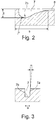
- the recess 7 runs in continuation of the course of the transverse incision 6 over the tire shoulder in the direction of a tire sidewall (not shown) and is essentially straight. Like the cross-section in Fig. 3 shows, the recess 7 is limited by the radial direction at an angle ⁇ of 2 ° to 7 ° extending side recess walls 7a and a recess bottom 7b. Fig. 2 shows the course of the recess bottom 7b along the longitudinal extension of the recess 7.
- the recess 7 is elongated trapezoidal in plan view, one of the incision walls of the transverse incision 6 being continued as one of the recess walls 7a delimiting the recess 7 at the base of the trapezoidal shape.
- the recess 7 has an in particular constant width b over up to 80% to 100% of its extension length e ( Fig. 3 ) from 1.50 mm to 2.50 mm.
- the depth of the incision 8 is 0.80 mm to 1.20 mm.
- the longitudinal extension of the recess 7 is trough-shaped, so that the recess 7 has a trough 7c with its greatest depth t of 50% to 80% of the profile depth.
- the depression 7c in the depression bottom 7b preferably runs along an arc of a circle with a radius r of 3.00 mm to 6.00 mm, in particular 5.00 mm. In the direction of the incision 8, the recess 7 becomes continuously shallower, the recess bottom 7b therefore rises continuously and finally merges into the shallow incision 8.
- Another incision 9 branches off from the inside end of the tread of the recess 7 at the tread edge L, which has two sections 9a, 9b running at an obtuse angle of in particular 110 ° to 150 ° to each other, of which the first section 9a adjoins the recess 7 and below runs at an acute angle of 40 ° to 70 ° to the recess 7.
- the second section 9b runs in particular parallel to the recess 7.
- the incisions 9 each have an in particular constant width of 0.4 mm to 1.0 mm and a depth of 0.8 mm to 1.2 mm.
- the trough-shaped recesses 7 form pockets in a particularly effective manner for receiving and compacting snow and slush on the corresponding subsoil and especially when cornering. During normal driving and when driving on solid ground, these pockets and the outer edges of the depressions 7 do not come into contact with the ground.
Landscapes
- Engineering & Computer Science (AREA)
- Mechanical Engineering (AREA)
- Tires In General (AREA)
Abstract
Description
- Die Erfindung betrifft einen Fahrzeugluftreifen in Radialbauart mit einem Laufstreifen mit zumindest einer schulterseitigen Profilrippe, in welcher in axialer Richtung Quereinschnitte verlaufen, welche eine Breite von 0,40 mm bis 0,80 mm aufweisen und zumindest bis zum seitlichen Rand der Bodenaufstandsfläche des Reifens verlaufen.
- Ein derartiger Fahrzeugluftreifen ist beispielsweise aus der
WO 2016/128086 A1 bekannt. Die Quereinschnitte in der schulterseitigen Profilrippe laufen über die Bodenaufstandsfläche hinaus und enden hier mit auslaufenden Einschnittabschnitten. Eine der beiden Einschnittwände der Quereinschnitte ist zur Laufstreifenperipherie angefast. Ein Laufstreifen mit derart gestalteten schulterseitigen Profilrippen soll gute Bremseigenschaften auf trockener und nasser Fahrbahn und eine gute Wasserableitung zur Außenschulterseite des Reifens aufweisen. - Der Erfindung liegt die Aufgabe zugrunde, bei einem Reifen der eingangs genannten Art im Außenschulterbereich eine verbesserte Griffperformance beim Fahren auf weichem Untergrund, beispielsweise auf Schnee, Schneematsch oder sonstigem matschigem Untergrund, insbesondere bei Kurvenfahrt sicherzustellen, also dann, wenn einer der Außenschulterbereiche mit dem weichem Untergrund in Kontakt kommt.
- Gelöst wird die gestellte Aufgabe erfindungsgemäß dadurch, dass an die Quereinschnitte außerhalb der Bodenaufstandsfläche, im Außenschulterbereich, jeweils eine langgestreckte Vertiefung anschließt, welche über 80 % bis 100 % ihrer Erstreckungslänge e eine Breite von 1,50 mm bis 3,00 mm aufweist und unmittelbar an den Quereinschnitte anschließend sowie in Richtung ihrer Längserstreckung muldenförmig vertieft ist und im Bereich der Mulde ihre größte Tiefe von 60 % bis 80 % der Profiltiefe aufweist.
- Unmittelbar an die Bodenaufstandsfläche anschließend befinden sich bei erfindungsgemäßen Reifen im Außenschulterbereich Vertiefungen, die vor allem bei Kurvenfahrt auf weichem Untergrund an der Außenseite der Außenschulter zusätzlich Griffkanten zur Verfügung stellen. Durch ein Eindringen und Verdichten des weichen Materials in den Mulden der Vertiefungen wird ein grifferhöhender Effekt erzielt.
- Bei einer bevorzugten Ausführung nimmt die Tiefe Vertiefung entlang ihrer Erstreckung im Außenschulterbereich kontinuierlich und bis auf 0,80 mm bis 1,00 mm ab. Der Tiefenverlauf ist daher an die Rundung des Reifens im Außenschulterbereich gut angepasst, wobei die größte Tiefe im Bereich der Mulde und beim Laufstreifenrand für einen optimalen grifferhöhender Effekt sorgt.
- Für ein optimales Verdichten von weichem Untergrundmaterial in den Mulden der Vertiefungen bei Kurvenfahrt ist es vorteilhaft, wenn die Mulde der Vertiefung, in der Längserstreckung der Vertiefung betrachtet, entlang eines Kreisbogens mit einem Radius von 3,00 mm bis 6,00 mm, insbesondere 5,00 mm, verläuft. Bei einer bevorzugten Erstreckungslänge von 17,00 mm bis 30,00 mm ist auch auf besonders weichem Untergrund, beispielsweise auf frisch gefallenem Schnee, die Wirkung der Vertiefungen als grifferhöhend sichergestellt.
- Bevorzugt sind die Vertiefungen in Draufsicht trapezförmig oder rechteckig.
- Bei einer weiteren bevorzugten Ausgestaltung zweigt vom laufstreifeninnenseitigen Ende der Vertiefungen beim Laufstreifenrand jeweils ein Einschnitt ab, welcher zwei zueinander unter einem stumpfen Winkel von insbesondere 110° bis 150° verlaufende Abschnitte aufweist, vor welchen der erste an die Vertiefung anschließt und unter einem spitzen Winkel von insbesondere 40° bis 70° zur Vertiefung verläuft. Diese weiteren, im Bereich der Vertiefungen an der Außenschulter verlaufenden Einschnitte stellen zusätzliche Griffkanten zur Verfügung. Diesbezüglich ist es besonders vorteilhaft, wenn jeweils der zweite Abschnitt der Einschnitte parallel zu den Vertiefungen verläuft.
- Bevorzugt weisen diese Einschnitte eine insbesondere konstante Breite von 0,40 mm bis 1,00 mm und eine Tiefe von 0,80 mm bis 1,20 mm auf.
- Weitere Merkmale, Vorteile und Einzelheiten der Erfindung werden nun anhand der schematischen Zeichnung, die ein Ausführungsbeispiel darstellt, näher beschrieben. Dabei zeigen
-
Fig. 1 eine Draufsicht (Projektion in die Ebene) eines schulterseitigen Umfangsabschnittes eines Laufstreifens eines Fahrzeugluftreifens, -
Fig. 2 eine Schnittdarstellung entlang der Linie II-II derFig. 1 und -
Fig. 3 eine Schnittdarstellung entlang der Linie III-III derFig. 1 . -
Fig. 1 zeigt einen Umfangsabschnitt einer schulterseitig verlaufenden Profilrippe 1 eines Fahrzeugluftreifens in Radialbauart, insbesondere für Personenkraftwagen, Vans oder Light - Trucks. Die Profilrippe 1 ist in Richtung zur Laufstreifenmitte durch eine in Umfangsrichtung umlaufende, inFig. 1 angedeutete und zumindest abschnittsweise in der vorgesehenen Profiltiefe ausgeführten Umfangsrille 2 von weiteren Profilstrukturen des Laufstreifens, beispielsweise Blockreihen oder weiteren Profilrippen, getrennt. Bei der zweiten, nicht gezeigten Reifenschulter ist vorzugsweise eine zur Profilrippe 1 analoge bzw. gleich gestaltete Profilrippe vorgesehen. - In
Fig. 1 kennzeichnet die Linie L den einen seitlichen Rand der Bodenaufstandsfläche bzw. des bodenberührenden Teils des Laufstreifens. Die Bodenaufstandsfläche weist eine Breite B (inFig. 1 angedeutet) auf und entspricht dem statisch ermittelten Footprint gemäß E.T.R.T.O. -Standards, Last bei 70 % der maximalen Tragfähigkeit bei einem Innendruck von 85 %, wobei der Reifen auf einer Normfelge montiert ist. Die schulterseitige Profilrippe 1 befindet sich daher zum Teil innerhalb der Bodenaufstandsfläche und zum Teil in der Schulterrundung des Reifens, außerhalb der Bodenaufstandsfläche. Der bodenberührende Teil der Profilrippe 1 weist eine Breite bp von 20 % bis 30 % der Breite B auf. - Innerhalb des bodenberührenden Teils weist die Profilrippe 1 durch Quereinschnitte 3, Querrillen 5 und bogenförmig verlaufenden Einschnitten 4 gebildete blockartige Rippenelemente 1a auf, die in Umfangsrichtung aneinander anschließen. Die Quereinschnitte 3 enden laufstreifeninnenseitig innerhalb der Profilrippe 1 und münden in die Querrillen 3, welche außerhalb der Bodenaufstandsfläche mit einem verbreiterten, seichten Abschnitt auslaufen. Die bogenförmigen Einschnitte 4 verbinden die laufstreifeninnenseitigen Enden bzw. Endabschnitte der in Umfangsrichtung aufeinanderfolgenden Quereinschnitte 3, die Wölbung der Bogenform weist zur Umfangsrille 2. Zwischen den bogenförmigen Einschnitten 4 und der Umfangsrille 2 befindet sich ein unstrukturierter Profilrippenstreifen 1b vor.
- Etwa mittig zwischen den in Umfangsrichtung benachbarten Quereinschnitten 3, daher etwa mittig in jedem Rippenelement 1a, verläuft jeweils ein weiterer Quereinschnitt 6, welcher außerhalb der Bodenaufstandsfläche und beim seitlichen Laufstreifenrand L in eine langestreckte Vertiefung 7 einmündet, welche eine Erstreckungslänge e von 17,0 mm bis 30, 0 mm aufweist. Die Quereinschnitte 3 und 6 sowie die bogenförmigen Einschnitte 4 weisen eine Breite von 0,4 mm bis 1,0 mm auf. Die Tiefe der Quereinschnitte 3 und 6 kann zumindest abschnittsweise bis zu 85 % der Profiltiefe betragen, die Tiefe der bogenförmigen Einschnitte 4 beträgt 1,00 mm bis 3,50 mm. Die Quereinschnitte 6 enden bei der gezeigten Ausführung laufstreifeninnenseitig innerhalb der Rippensegmente 1a, können jedoch auch bis zu den bogenförmigen Einschnitten 4 und bei Ausführungen der Profilrippe 1 ohne Einschnitte 4 bis zur Umfangsrille 2 verlaufen.
- Die Vertiefung 7 verläuft in Fortsetzung des Verlaufes des Quereinschnittes 6 über die Reifenschulter in Richtung einer nicht gezeigter Reifenseitenwand und im Wesentlichen gerade. Wie die Querschnittsdarstellung in
Fig. 3 zeigt, ist die Vertiefung 7 von zur radialen Richtung unter einem Winkel α von 2° bis 7° verlaufenden seitlichen Vertiefungswänden 7a und einem Vertiefungsboden 7b begrenzt.Fig. 2 zeigt den Verlauf des Vertiefungsboden 7b entlang der Längserstreckung der Vertiefung 7. Die Vertiefung 7 ist beim gezeigten Ausführungsbeispiel in Draufsicht langgestreckt trapezförmig, wobei an der Basis der Trapezform eine der Einschnittwände des Quereinschnittes 6 als eine der die Vertiefung 7 begrenzenden Vertiefungswände 7a fortgesetzt ist. In Draufsicht betrachtet weist die Vertiefung 7 über bis 80 % bis 100 % ihrer Erstreckungslänge e eine insbesondere konstante Breite b (Fig. 3 ) von 1,50 mm bis 2,50 mm auf. - Am reifenschulterseitigen Ende der Vertiefung 7 schließt ein kurzer, etwa 3,00 mm bis 5,00 mm langer Einschnitt 8, mit dem Quereinschnitt 6 fluchtend, an. Der Einschnitt 8 weist ebenso wie die Einschnitte 6 eine Breite von 0,4 mm bis 1,0 mm auf. Die Tiefe des Einschnittes 8 beträgt 0,80 mm bis 1,20 mm. An ihrem dem Quereinschnitt 6 zugewandten Endbereich ist die Vertiefung 7 in ihrer Längserstreckung muldenförmig vertieft, sodass die Vertiefung 7 eine Mulde 7c mit ihrer größten Tiefe t von 50 % bis 80 % der Profiltiefe aufweist. Die Mulde 7c im Vertiefungsboden 7b verläuft vorzugsweise entlang eines Kreisbogens mit einem Radius r von 3,00 mm bis 6,00 mm, insbesondere 5,00 mm. In Richtung zum Einschnitt 8 wird die Vertiefung 7 kontinuierlich seichter, der Vertiefungsboden 7b steigt daher kontinuierlich an und geht schließlich in den seichten Einschnitt 8 über.
- Vom laufstreifeninnenseitigen Ende der Vertiefung 7 beim Laufstreifenrand L zweigt ein weiterer Einschnitt 9 ab, welcher zwei zueinander unter einem stumpfen Winkel von insbesondere 110° bis 150° verlaufende Abschnitte 9a, 9b aufweist, von welchen der erste Abschnitt 9a an die Vertiefung 7 anschließt und unter einem spitzen Winkel von 40° bis 70° zur Vertiefung 7 verläuft. Der zweite Abschnitt 9b verläuft insbesondere parallel zur Vertiefung 7. Die Einschnitte 9 weisen jeweils eine insbesondere konstante Breite von 0,4 mm bis 1,0 mm und eine Tiefe von 0,8 mm bis 1,2 mm auf.
- Die muldenförmig vertieften Vertiefungen 7 bilden auf besonders effektive Weise Taschen zur Aufnahme und Verdichtung von Schnee und Matsch auf entsprechendem Untergrrund und speziell bei Kurvenfahrt. Im normalen Fahrbetrieb und beim Fahren auf festem Untergrund kommen diese Taschen sowie die Außenkanten der Vertiefungen 7 mit dem Untergrund nicht in Kontakt.
-
- 1
- Profilrippe
- 1 a
- Profilrippensegment
- 1 b
- Profilrippenstreifen
- 2
- Umfangsrille
- 3
- Quereinschnitt
- 4
- bogenförmiger Einschnitt
- 6
- Quereinschnitt
- 7
- Vertiefung
- 7a
- Vertiefungswand
- 7b
- Vertiefungsboden
- 7c
- Mulde
- 8
- Einschnitt
- 9
- Einschnitt
- 9a, 9b
- Abschnitt
- bp
- Breite der Profilrippe 1
- b
- Breite der Vertiefung 7
- B
- Laufstreifenbreite
- L
- Linie
- t
- Tiefe
- T
- Profiltiefe
- e
- Erstreckungslänge
- r
- Radius
Claims (8)
- Fahrzeugluftreifen in Radialbauart mit einem Laufstreifen mit zumindest einer schulterseitigen Profilrippe (1), in welcher in axialer Richtung Quereinschnitte (6) verlaufen, welche eine Breite von 0,40 mm bis 1,00 mm aufweisen und zumindest bis zum seitlichen Rand der Bodenaufstandsfläche des Reifens verlaufen,
dadurch gekennzeichnet,
dass an die Quereinschnitte (6) außerhalb der Bodenaufstandsfläche, im Außenschulterbereich, jeweils eine langgestreckte Vertiefung (7) anschließt, welche über 80 % bis 100 % ihrer Erstreckungslänge (e) eine Breite von 1,50 mm bis 3,00 mm aufweist und unmittelbar an den Quereinschnitt (6) anschließend sowie in Richtung ihrer Längserstreckung muldenförmig vertieft ist und im Bereich der Mulde (7c) ihre größte Tiefe (t) von 60 % bis 80 % der Profiltiefe aufweist. - Fahrzeugluftreifen nach Anspruch 1, dadurch gekennzeichnet, dass die Tiefe (t) der Vertiefung (7) entlang ihre Erstreckung im Außenschulterbereich kontinuierlich und bis auf eine Tiefe von 0,80 mm bis 1,00 mm abnimmt.
- Fahrzeugluftreifen nach Anspruch 1 oder 2, dadurch gekennzeichnet, dass die Mulde (7c) der Vertiefung (7), in der Längserstreckung der Vertiefung betrachtet, entlang eines Kreisbogens mit einem Radius (r) von 3,00 mm bis 6,00 mm, insbesondere 5,00 mm, verläuft.
- Fahrzeugluftreifen nach einem der Ansprüche 1 bis 3, dadurch gekennzeichnet, dass die Vertiefung (7) eine Erstreckungslänge (e) von 17,00 mm bis 30,00 mm aufweist.
- Fahrzeugluftreifen nach einem der Ansprüche 1 bis 4, dadurch gekennzeichnet, dass die Vertiefung (7) in Draufsicht trapezförmig oder rechteckig ist.
- Fahrzeugluftreifen nach einem der Ansprüche 1 bis 5, dadurch gekennzeichnet, dass vom laufstreifeninnenseitigen Ende der Vertiefung (7) beim Laufstreifenrand (L) ein Einschnitt (9) abzweigt, welcher zwei zueinander unter einem stumpfen Winkel von insbesondere 110° bis 150° verlaufende Abschnitte (9a, 9b) aufweist, von welchen der erste an die Vertiefung (7) anschließt und unter einem spitzen Winkel von insbesondere 40° bis 70° zur Vertiefung (7) verläuft.
- Fahrzeugluftreifen nach Anspruch 6, dadurch gekennzeichnet, dass der zweite Abschnitt (9b) des Einschnittes (9) parallel zur Vertiefung (7) verläuft.
- Fahrzeugluftreifen nach Anspruch 6 oder 7, dadurch gekennzeichnet, dass der Einschnitt (9) eine insbesondere konstante Breite von 0,4 mm bis 1,0 mm und eine Tiefe von 0,8 mm bis 1,2 mm aufweist.
Applications Claiming Priority (1)
| Application Number | Priority Date | Filing Date | Title |
|---|---|---|---|
| DE102020204070.2A DE102020204070A1 (de) | 2020-03-30 | 2020-03-30 | Fahrzeugluftreifen |
Publications (2)
| Publication Number | Publication Date |
|---|---|
| EP3888949A1 true EP3888949A1 (de) | 2021-10-06 |
| EP3888949B1 EP3888949B1 (de) | 2023-08-02 |
Family
ID=73646246
Family Applications (1)
| Application Number | Title | Priority Date | Filing Date |
|---|---|---|---|
| EP20210726.4A Active EP3888949B1 (de) | 2020-03-30 | 2020-11-30 | Fahrzeugluftreifen |
Country Status (2)
| Country | Link |
|---|---|
| EP (1) | EP3888949B1 (de) |
| DE (1) | DE102020204070A1 (de) |
Cited By (1)
| Publication number | Priority date | Publication date | Assignee | Title |
|---|---|---|---|---|
| WO2023208301A1 (de) | 2022-04-29 | 2023-11-02 | Continental Reifen Deutschland Gmbh | Fahrzeugluftreifen |
Citations (7)
| Publication number | Priority date | Publication date | Assignee | Title |
|---|---|---|---|---|
| EP2281698A1 (de) * | 2009-08-03 | 2011-02-09 | Sumitomo Rubber Industries, Ltd. | Luftreifen |
| WO2016128086A1 (de) | 2015-02-13 | 2016-08-18 | Continental Reifen Deutschland Gmbh | Fahrzeugluftreifen |
| US20180147893A1 (en) * | 2015-07-27 | 2018-05-31 | The Yokohama Rubber Co., Ltd. | Pneumatic Tire |
| US20180194171A1 (en) * | 2015-07-22 | 2018-07-12 | The Yokohama Rubber Co., Ltd. | Pneumatic Tire |
| DE112017002199T5 (de) * | 2016-04-26 | 2019-01-10 | The Yokohama Rubber Co., Ltd. | Luftreifen |
| US20190176527A1 (en) * | 2017-12-13 | 2019-06-13 | Toyo Tire & Rubber Co., Ltd. | Pneumatic tire |
| EP3572242A1 (de) * | 2018-05-22 | 2019-11-27 | Sumitomo Rubber Industries, Ltd. | Reifen |
-
2020
- 2020-03-30 DE DE102020204070.2A patent/DE102020204070A1/de not_active Withdrawn
- 2020-11-30 EP EP20210726.4A patent/EP3888949B1/de active Active
Patent Citations (7)
| Publication number | Priority date | Publication date | Assignee | Title |
|---|---|---|---|---|
| EP2281698A1 (de) * | 2009-08-03 | 2011-02-09 | Sumitomo Rubber Industries, Ltd. | Luftreifen |
| WO2016128086A1 (de) | 2015-02-13 | 2016-08-18 | Continental Reifen Deutschland Gmbh | Fahrzeugluftreifen |
| US20180194171A1 (en) * | 2015-07-22 | 2018-07-12 | The Yokohama Rubber Co., Ltd. | Pneumatic Tire |
| US20180147893A1 (en) * | 2015-07-27 | 2018-05-31 | The Yokohama Rubber Co., Ltd. | Pneumatic Tire |
| DE112017002199T5 (de) * | 2016-04-26 | 2019-01-10 | The Yokohama Rubber Co., Ltd. | Luftreifen |
| US20190176527A1 (en) * | 2017-12-13 | 2019-06-13 | Toyo Tire & Rubber Co., Ltd. | Pneumatic tire |
| EP3572242A1 (de) * | 2018-05-22 | 2019-11-27 | Sumitomo Rubber Industries, Ltd. | Reifen |
Cited By (2)
| Publication number | Priority date | Publication date | Assignee | Title |
|---|---|---|---|---|
| WO2023208301A1 (de) | 2022-04-29 | 2023-11-02 | Continental Reifen Deutschland Gmbh | Fahrzeugluftreifen |
| DE102022204217A1 (de) | 2022-04-29 | 2023-11-02 | Continental Reifen Deutschland Gmbh | Fahrzeugluftreifen |
Also Published As
| Publication number | Publication date |
|---|---|
| EP3888949B1 (de) | 2023-08-02 |
| DE102020204070A1 (de) | 2021-09-30 |
Similar Documents
| Publication | Publication Date | Title |
|---|---|---|
| EP3388256B1 (de) | Fahrzeugluftreifen | |
| DE102007061148A1 (de) | Fahrzeugluftreifen | |
| EP3256334B1 (de) | Fahrzeugluftreifen | |
| EP3589501A1 (de) | Fahrzeugluftreifen | |
| EP3300926B1 (de) | Fahrzeugluftreifen | |
| EP2465708B1 (de) | Fahrzeugluftreifen | |
| EP4347277B1 (de) | Fahrzeugluftreifen | |
| EP3724006A1 (de) | Nutzfahrzeugreifen | |
| EP3256335B1 (de) | Fahrzeugluftreifen | |
| EP2138327B1 (de) | Laufflächenprofil für einen Fahrzeugluftreifen | |
| EP3441241B1 (de) | Fahrzeugluftreifen | |
| EP3888949B1 (de) | Fahrzeugluftreifen | |
| EP4058304B1 (de) | Fahrzeugluftreifen | |
| EP2138329B1 (de) | Laufflächenprofil für einen Fahrzeugluftreifen | |
| EP3750723B1 (de) | Fahrzeugluftreifen | |
| EP3300925B1 (de) | Fahrzeugluftreifen | |
| EP4144542B1 (de) | Fahrzeugluftreifen | |
| EP2138328B1 (de) | Fahrzeugluftreifen | |
| EP3831619B1 (de) | Fahrzeugluftreifen | |
| EP3686034B1 (de) | Fahrzeugluftreifen | |
| EP4003760B1 (de) | Fahrzeugluftreifen | |
| EP3418076B1 (de) | Fahrzeugluftreifen | |
| WO2023036375A1 (de) | Fahrzeugluftreifen | |
| EP2090443B1 (de) | Fahrzeugluftreifen | |
| EP4140774B1 (de) | Fahrzeugreifen |
Legal Events
| Date | Code | Title | Description |
|---|---|---|---|
| PUAI | Public reference made under article 153(3) epc to a published international application that has entered the european phase |
Free format text: ORIGINAL CODE: 0009012 |
|
| STAA | Information on the status of an ep patent application or granted ep patent |
Free format text: STATUS: THE APPLICATION HAS BEEN PUBLISHED |
|
| AK | Designated contracting states |
Kind code of ref document: A1 Designated state(s): AL AT BE BG CH CY CZ DE DK EE ES FI FR GB GR HR HU IE IS IT LI LT LU LV MC MK MT NL NO PL PT RO RS SE SI SK SM TR |
|
| STAA | Information on the status of an ep patent application or granted ep patent |
Free format text: STATUS: REQUEST FOR EXAMINATION WAS MADE |
|
| 17P | Request for examination filed |
Effective date: 20220406 |
|
| RBV | Designated contracting states (corrected) |
Designated state(s): AL AT BE BG CH CY CZ DE DK EE ES FI FR GB GR HR HU IE IS IT LI LT LU LV MC MK MT NL NO PL PT RO RS SE SI SK SM TR |
|
| RIC1 | Information provided on ipc code assigned before grant |
Ipc: B60C 11/03 20060101ALN20221220BHEP Ipc: B60C 11/01 20060101ALI20221220BHEP Ipc: B60C 11/12 20060101AFI20221220BHEP |
|
| RIC1 | Information provided on ipc code assigned before grant |
Ipc: B60C 11/03 20060101ALN20230130BHEP Ipc: B60C 11/01 20060101ALI20230130BHEP Ipc: B60C 11/12 20060101AFI20230130BHEP |
|
| GRAP | Despatch of communication of intention to grant a patent |
Free format text: ORIGINAL CODE: EPIDOSNIGR1 |
|
| STAA | Information on the status of an ep patent application or granted ep patent |
Free format text: STATUS: GRANT OF PATENT IS INTENDED |
|
| INTG | Intention to grant announced |
Effective date: 20230313 |
|
| RIN1 | Information on inventor provided before grant (corrected) |
Inventor name: HEIDE, THORSTEN Inventor name: PAGAC, LUBOMIR Inventor name: HENZE, EUGEN Inventor name: OEZUEDURU, AHMET |
|
| GRAS | Grant fee paid |
Free format text: ORIGINAL CODE: EPIDOSNIGR3 |
|
| GRAA | (expected) grant |
Free format text: ORIGINAL CODE: 0009210 |
|
| STAA | Information on the status of an ep patent application or granted ep patent |
Free format text: STATUS: THE PATENT HAS BEEN GRANTED |
|
| P01 | Opt-out of the competence of the unified patent court (upc) registered |
Effective date: 20230602 |
|
| AK | Designated contracting states |
Kind code of ref document: B1 Designated state(s): AL AT BE BG CH CY CZ DE DK EE ES FI FR GB GR HR HU IE IS IT LI LT LU LV MC MK MT NL NO PL PT RO RS SE SI SK SM TR |
|
| REG | Reference to a national code |
Ref country code: GB Ref legal event code: FG4D Free format text: NOT ENGLISH |
|
| REG | Reference to a national code |
Ref country code: CH Ref legal event code: EP |
|
| REG | Reference to a national code |
Ref country code: DE Ref legal event code: R096 Ref document number: 502020004474 Country of ref document: DE |
|
| REG | Reference to a national code |
Ref country code: IE Ref legal event code: FG4D Free format text: LANGUAGE OF EP DOCUMENT: GERMAN |
|
| REG | Reference to a national code |
Ref country code: LT Ref legal event code: MG9D |
|
| REG | Reference to a national code |
Ref country code: NL Ref legal event code: MP Effective date: 20230802 |
|
| PG25 | Lapsed in a contracting state [announced via postgrant information from national office to epo] |
Ref country code: GR Free format text: LAPSE BECAUSE OF FAILURE TO SUBMIT A TRANSLATION OF THE DESCRIPTION OR TO PAY THE FEE WITHIN THE PRESCRIBED TIME-LIMIT Effective date: 20231103 |
|
| PG25 | Lapsed in a contracting state [announced via postgrant information from national office to epo] |
Ref country code: IS Free format text: LAPSE BECAUSE OF FAILURE TO SUBMIT A TRANSLATION OF THE DESCRIPTION OR TO PAY THE FEE WITHIN THE PRESCRIBED TIME-LIMIT Effective date: 20231202 |
|
| PG25 | Lapsed in a contracting state [announced via postgrant information from national office to epo] |
Ref country code: SE Free format text: LAPSE BECAUSE OF FAILURE TO SUBMIT A TRANSLATION OF THE DESCRIPTION OR TO PAY THE FEE WITHIN THE PRESCRIBED TIME-LIMIT Effective date: 20230802 Ref country code: RS Free format text: LAPSE BECAUSE OF FAILURE TO SUBMIT A TRANSLATION OF THE DESCRIPTION OR TO PAY THE FEE WITHIN THE PRESCRIBED TIME-LIMIT Effective date: 20230802 Ref country code: PT Free format text: LAPSE BECAUSE OF FAILURE TO SUBMIT A TRANSLATION OF THE DESCRIPTION OR TO PAY THE FEE WITHIN THE PRESCRIBED TIME-LIMIT Effective date: 20231204 Ref country code: NO Free format text: LAPSE BECAUSE OF FAILURE TO SUBMIT A TRANSLATION OF THE DESCRIPTION OR TO PAY THE FEE WITHIN THE PRESCRIBED TIME-LIMIT Effective date: 20231102 Ref country code: NL Free format text: LAPSE BECAUSE OF FAILURE TO SUBMIT A TRANSLATION OF THE DESCRIPTION OR TO PAY THE FEE WITHIN THE PRESCRIBED TIME-LIMIT Effective date: 20230802 Ref country code: LV Free format text: LAPSE BECAUSE OF FAILURE TO SUBMIT A TRANSLATION OF THE DESCRIPTION OR TO PAY THE FEE WITHIN THE PRESCRIBED TIME-LIMIT Effective date: 20230802 Ref country code: LT Free format text: LAPSE BECAUSE OF FAILURE TO SUBMIT A TRANSLATION OF THE DESCRIPTION OR TO PAY THE FEE WITHIN THE PRESCRIBED TIME-LIMIT Effective date: 20230802 Ref country code: IS Free format text: LAPSE BECAUSE OF FAILURE TO SUBMIT A TRANSLATION OF THE DESCRIPTION OR TO PAY THE FEE WITHIN THE PRESCRIBED TIME-LIMIT Effective date: 20231202 Ref country code: HR Free format text: LAPSE BECAUSE OF FAILURE TO SUBMIT A TRANSLATION OF THE DESCRIPTION OR TO PAY THE FEE WITHIN THE PRESCRIBED TIME-LIMIT Effective date: 20230802 Ref country code: GR Free format text: LAPSE BECAUSE OF FAILURE TO SUBMIT A TRANSLATION OF THE DESCRIPTION OR TO PAY THE FEE WITHIN THE PRESCRIBED TIME-LIMIT Effective date: 20231103 Ref country code: FI Free format text: LAPSE BECAUSE OF FAILURE TO SUBMIT A TRANSLATION OF THE DESCRIPTION OR TO PAY THE FEE WITHIN THE PRESCRIBED TIME-LIMIT Effective date: 20230802 |
|
| PG25 | Lapsed in a contracting state [announced via postgrant information from national office to epo] |
Ref country code: PL Free format text: LAPSE BECAUSE OF FAILURE TO SUBMIT A TRANSLATION OF THE DESCRIPTION OR TO PAY THE FEE WITHIN THE PRESCRIBED TIME-LIMIT Effective date: 20230802 |
|
| RAP4 | Party data changed (patent owner data changed or rights of a patent transferred) |
Owner name: CONTINENTAL REIFEN DEUTSCHLAND GMBH |
|
| REG | Reference to a national code |
Ref country code: DE Ref legal event code: R081 Ref document number: 502020004474 Country of ref document: DE Owner name: CONTINENTAL REIFEN DEUTSCHLAND GMBH, DE Free format text: FORMER OWNER: CONTINENTAL REIFEN DEUTSCHLAND GMBH, 30165 HANNOVER, DE |
|
| PG25 | Lapsed in a contracting state [announced via postgrant information from national office to epo] |
Ref country code: ES Free format text: LAPSE BECAUSE OF FAILURE TO SUBMIT A TRANSLATION OF THE DESCRIPTION OR TO PAY THE FEE WITHIN THE PRESCRIBED TIME-LIMIT Effective date: 20230802 |
|
| PG25 | Lapsed in a contracting state [announced via postgrant information from national office to epo] |
Ref country code: SM Free format text: LAPSE BECAUSE OF FAILURE TO SUBMIT A TRANSLATION OF THE DESCRIPTION OR TO PAY THE FEE WITHIN THE PRESCRIBED TIME-LIMIT Effective date: 20230802 Ref country code: RO Free format text: LAPSE BECAUSE OF FAILURE TO SUBMIT A TRANSLATION OF THE DESCRIPTION OR TO PAY THE FEE WITHIN THE PRESCRIBED TIME-LIMIT Effective date: 20230802 Ref country code: ES Free format text: LAPSE BECAUSE OF FAILURE TO SUBMIT A TRANSLATION OF THE DESCRIPTION OR TO PAY THE FEE WITHIN THE PRESCRIBED TIME-LIMIT Effective date: 20230802 Ref country code: EE Free format text: LAPSE BECAUSE OF FAILURE TO SUBMIT A TRANSLATION OF THE DESCRIPTION OR TO PAY THE FEE WITHIN THE PRESCRIBED TIME-LIMIT Effective date: 20230802 Ref country code: DK Free format text: LAPSE BECAUSE OF FAILURE TO SUBMIT A TRANSLATION OF THE DESCRIPTION OR TO PAY THE FEE WITHIN THE PRESCRIBED TIME-LIMIT Effective date: 20230802 Ref country code: CZ Free format text: LAPSE BECAUSE OF FAILURE TO SUBMIT A TRANSLATION OF THE DESCRIPTION OR TO PAY THE FEE WITHIN THE PRESCRIBED TIME-LIMIT Effective date: 20230802 Ref country code: SK Free format text: LAPSE BECAUSE OF FAILURE TO SUBMIT A TRANSLATION OF THE DESCRIPTION OR TO PAY THE FEE WITHIN THE PRESCRIBED TIME-LIMIT Effective date: 20230802 |
|
| REG | Reference to a national code |
Ref country code: DE Ref legal event code: R097 Ref document number: 502020004474 Country of ref document: DE |
|
| PG25 | Lapsed in a contracting state [announced via postgrant information from national office to epo] |
Ref country code: IT Free format text: LAPSE BECAUSE OF FAILURE TO SUBMIT A TRANSLATION OF THE DESCRIPTION OR TO PAY THE FEE WITHIN THE PRESCRIBED TIME-LIMIT Effective date: 20230802 |
|
| PLBE | No opposition filed within time limit |
Free format text: ORIGINAL CODE: 0009261 |
|
| STAA | Information on the status of an ep patent application or granted ep patent |
Free format text: STATUS: NO OPPOSITION FILED WITHIN TIME LIMIT |
|
| REG | Reference to a national code |
Ref country code: CH Ref legal event code: PL |
|
| PG25 | Lapsed in a contracting state [announced via postgrant information from national office to epo] |
Ref country code: MC Free format text: LAPSE BECAUSE OF FAILURE TO SUBMIT A TRANSLATION OF THE DESCRIPTION OR TO PAY THE FEE WITHIN THE PRESCRIBED TIME-LIMIT Effective date: 20230802 |
|
| 26N | No opposition filed |
Effective date: 20240503 |
|
| PG25 | Lapsed in a contracting state [announced via postgrant information from national office to epo] |
Ref country code: LU Free format text: LAPSE BECAUSE OF NON-PAYMENT OF DUE FEES Effective date: 20231130 |
|
| PG25 | Lapsed in a contracting state [announced via postgrant information from national office to epo] |
Ref country code: CH Free format text: LAPSE BECAUSE OF NON-PAYMENT OF DUE FEES Effective date: 20231130 |
|
| PG25 | Lapsed in a contracting state [announced via postgrant information from national office to epo] |
Ref country code: MC Free format text: LAPSE BECAUSE OF FAILURE TO SUBMIT A TRANSLATION OF THE DESCRIPTION OR TO PAY THE FEE WITHIN THE PRESCRIBED TIME-LIMIT Effective date: 20230802 Ref country code: LU Free format text: LAPSE BECAUSE OF NON-PAYMENT OF DUE FEES Effective date: 20231130 Ref country code: CH Free format text: LAPSE BECAUSE OF NON-PAYMENT OF DUE FEES Effective date: 20231130 Ref country code: SI Free format text: LAPSE BECAUSE OF FAILURE TO SUBMIT A TRANSLATION OF THE DESCRIPTION OR TO PAY THE FEE WITHIN THE PRESCRIBED TIME-LIMIT Effective date: 20230802 |
|
| REG | Reference to a national code |
Ref country code: BE Ref legal event code: MM Effective date: 20231130 |
|
| REG | Reference to a national code |
Ref country code: IE Ref legal event code: MM4A |
|
| PG25 | Lapsed in a contracting state [announced via postgrant information from national office to epo] |
Ref country code: IE Free format text: LAPSE BECAUSE OF NON-PAYMENT OF DUE FEES Effective date: 20231130 |
|
| PG25 | Lapsed in a contracting state [announced via postgrant information from national office to epo] |
Ref country code: BE Free format text: LAPSE BECAUSE OF NON-PAYMENT OF DUE FEES Effective date: 20231130 |
|
| PG25 | Lapsed in a contracting state [announced via postgrant information from national office to epo] |
Ref country code: FR Free format text: LAPSE BECAUSE OF NON-PAYMENT OF DUE FEES Effective date: 20231130 |
|
| PG25 | Lapsed in a contracting state [announced via postgrant information from national office to epo] |
Ref country code: IE Free format text: LAPSE BECAUSE OF NON-PAYMENT OF DUE FEES Effective date: 20231130 Ref country code: FR Free format text: LAPSE BECAUSE OF NON-PAYMENT OF DUE FEES Effective date: 20231130 Ref country code: BE Free format text: LAPSE BECAUSE OF NON-PAYMENT OF DUE FEES Effective date: 20231130 |
|
| PG25 | Lapsed in a contracting state [announced via postgrant information from national office to epo] |
Ref country code: BG Free format text: LAPSE BECAUSE OF FAILURE TO SUBMIT A TRANSLATION OF THE DESCRIPTION OR TO PAY THE FEE WITHIN THE PRESCRIBED TIME-LIMIT Effective date: 20230802 |
|
| PG25 | Lapsed in a contracting state [announced via postgrant information from national office to epo] |
Ref country code: BG Free format text: LAPSE BECAUSE OF FAILURE TO SUBMIT A TRANSLATION OF THE DESCRIPTION OR TO PAY THE FEE WITHIN THE PRESCRIBED TIME-LIMIT Effective date: 20230802 |
|
| GBPC | Gb: european patent ceased through non-payment of renewal fee |
Effective date: 20241130 |
|
| PG25 | Lapsed in a contracting state [announced via postgrant information from national office to epo] |
Ref country code: CY Free format text: LAPSE BECAUSE OF FAILURE TO SUBMIT A TRANSLATION OF THE DESCRIPTION OR TO PAY THE FEE WITHIN THE PRESCRIBED TIME-LIMIT; INVALID AB INITIO Effective date: 20201130 |
|
| PG25 | Lapsed in a contracting state [announced via postgrant information from national office to epo] |
Ref country code: HU Free format text: LAPSE BECAUSE OF FAILURE TO SUBMIT A TRANSLATION OF THE DESCRIPTION OR TO PAY THE FEE WITHIN THE PRESCRIBED TIME-LIMIT; INVALID AB INITIO Effective date: 20201130 |
|
| PG25 | Lapsed in a contracting state [announced via postgrant information from national office to epo] |
Ref country code: GB Free format text: LAPSE BECAUSE OF NON-PAYMENT OF DUE FEES Effective date: 20241130 |
|
| PG25 | Lapsed in a contracting state [announced via postgrant information from national office to epo] |
Ref country code: TR Free format text: LAPSE BECAUSE OF FAILURE TO SUBMIT A TRANSLATION OF THE DESCRIPTION OR TO PAY THE FEE WITHIN THE PRESCRIBED TIME-LIMIT Effective date: 20230802 |
|
| PGFP | Annual fee paid to national office [announced via postgrant information from national office to epo] |
Ref country code: DE Payment date: 20251130 Year of fee payment: 6 |
|
| PGFP | Annual fee paid to national office [announced via postgrant information from national office to epo] |
Ref country code: AT Payment date: 20260113 Year of fee payment: 5 |